

Page 1
SINUMERIK 805
aaaaaaaaaaaaaaaaaaaaaaaaaaaaaaaaaaaaaaaaaaaaaaaaaaaaaaaaaaaaaaaaaaaaaaaaaaaaaaaaaaaaaaaaaaaaaaaaaaaaaaaaaaaaaaaaaaaaaaaaaaaaaaaaaaa
a
a
a
a
a
a
a
a
a
a
a
a
a
a
a
a
a
a
a
a
a
a
a
a
a
a
a
a
a
a
a
a
a
a
a
a
a
a
a
a
a
a
a
a
a
a
a
a
a
a
a
a
a
a
a
a
a
a
a
a
a
a
a
a
a
a
a
a
a
a
a
a
a
a
a
a
a
a
a
a
a
a
a
a
a
a
a
a
a
a
a
a
a
a
a
a
a
a
a
a
a
a
a
a
a
a
a
a
a
a
a
a
a
a
a
a
a
a
a
a
a
a
a
a
a
a
a
a
a
a
a
a
a
a
a
a
a
a
a
a
a
a
a
a
a
a
a
a
a
a
a
a
a
a
a
a
a
a
a
a
a
a
a
a
a
a
a
a
a
a
a
a
a
a
a
a
a
a
a
a
a
a
a
a
a
a
a
a
a
a
a
a
a
a
a
a
a
a
a
a
a
a
a
a
a
a
a
a
a
a
a
a
a
a
a
a
a
a
a
a
a
a
a
a
a
a
a
a
a
a
a
a
a
a
a
a
a
a
a
a
a
a
a
a
a
a
a
a
a
a
a
a
a
a
a
a
a
a
aaaaaaaaaaaaaaaaaaaaaaaaaaaaaaaaaaaaaaaaaaaaaaaaaaaaaaaaaaaaaaaaaaaaaaaaaaaaaaaaaaaaaaaaaaaaaaaaaaaaaaaaaaaaaaaaaaaaaaaaaaaaaaaaaaa
a
a
a
a
a
a
a
a
a
a
a
a
a
a
Software Version 4
PLC Programming
aaaaaaaaaaaaaaaaaaaaaaaaaaaaaaaaaaaaaaaaaaaaaaaaaaaaaaaaaaaaaaaaaaaaaaaaaaaaaaaaaaaaaaaaaaaaaaaaaaaaaaaaaaaaaaaaaaaaaaaaaaaaaaaaa
aaaaaaaaaaaaaaaaaaaaaaaaaaaaaaaaaaaaaaaaaaaaaaaaaaaaaaaaaaaaaaaaaaaaaaaaaaaaaaaaaaaaaaaaaaaaaaaaaaaaaaaaaaaaaaaaaaaaaaaaaaaaaaaaa
aaaaaaaaaaaaaaaaaaaaaaaaaaaaaaaaaaaaaaaaaaaaaaaaaaaaaaaaaaaaaaaaaaaaaaaaaaaaaaaaaaaaaaaaaaaaaaaaaaaaaaaaaaaaaaaaaaaaaaaaaaaaaaaaa
aaaaaaaaaaaaaaaaaaaaaaaaaaaaaaaaaaaaaaaaaaaaaaaaaaaaaaaaaaaaaaaaaaaaaaaaaaaaaaaaaaaaaaaaaaaaaaaaaaaaaaaaaaaaaaaaaaaaaaaaaaaaaaaaa
aaaaaaaaaaaaaaaaaaaaaaaaaaaaaaaaaaaaaaaaaaaaaaaaaaaaaaaaaaaaaaaaaaaaaaaaaaaaaaaaaaaaaaaaaaaaaaaaaaaaaaaaaaaaaaaaaaaaaaaaaaaaaaaaa
Planning Guide 11.91 Edition
aaaaaaaaaaaaaaaaaaaaaaaaaaaaaaaaaaaaaaaaaaaaaaaaaaaaaaaaaaaaaaaaaaaaaaaaaaaaaaaaaaaaaaaaaaaaaaaaaaaaaaaaaaaaaaaaaaaaaaaaaaaaaaaaa
aaaaaaaaaaaaaaaaaaaaaaaaaaaaaaaaaaaaaaaaaaaaaaaaaaaaaaaaaaaaaaaaaaaaaaaaaaaaaaaaaaaaaaaaaaaaaaaaaaaaaaaaaaaaaaaaaaaaaaaaaaaaaaaaa
aaaaaaaaaaaaaaaaaaaaaaaaaaaaaaaaaaaaaaaaaaaaaaaaaaaaaaaaaaaaaaaaaaaaaaaaaaaaaaaaaaaaaaaaaaaaaaaaaaaaaaaaaaaaaaaaaaaaaaaaaaaaaaaaa
aaaaaaaaaaaaaaaaaaaaaaaaaaaaaaaaaaaaaaaaaaaaaaaaaaaaaaaaaaaaaaaaaaaaaaaaaaaaaaaaaaaaaaaaaaaaaaaaaaaaaaaaaaaaaaaaaaaaaaaaaaaaaaaaa
aaaaaaaaaaaaaaaaaaaaaaaaaaaaaaaaaaaaaaaaaaaaaaaaaaaaaaaaaaaaaaaaaaaaaaaaaaaaaaaaaaaaaaaaaaaaaaaaaaaaaaaaaaaaaaaaaaaaaaaaaaaaaaaaa
aaaaaaaaaaaaaaaaaaaaaaaaaaaaaaaaaaaaaaaaaaaaaaaaaaaaaaaaaaaaaaaaaaaaaaaaaaaaaaaaaaaaaaaaaaaaaaaaaaaaaaaaaaaaaaaaaaaaaaaaaaaaaaaaa
aaaaaaaaaaaaaaaaaaaaaaaaaaaaaaaaaaaaaaaaaaaaaaaaaaaaaaaaaaaaaaaaaaaaaaaaaaaaaaaaaaaaaaaaaaaaaaaaaaaaaaaaaaaaaaaaaaaaaaaaaaaaaaaaa
aaaaaaaaaaaaaaaaaaaaaaaaaaaaaaaaaaaaaaaaaaaaaaaaaaaaaaaaaaaaaaaaaaaaaaaaaaaaaaaaaaaaaaaaaaaaaaaaaaaaaaaaaaaaaaaaaaaaaaaaaaaaaaaaa
aaaaaaaaaaaaaaaaaaaaaaaaaaaaaaaaaaaaaaaaaaaaaaaaaaaaaaaaaaaaaaaaaaaaaaaaaaaaaaaaaaaaaaaaaaaaaaaaaaaaaaaaaaaaaaaaaaaaaaaaaaaaaaaaa
aaaaaaaaaaaaaaaaaaaaaaaaaaaaaaaaaaaaaaaaaaaaaaaaaaaaaaaaaaaaaaaaaaaaaaaaaaaaaaaaaaaaaaaaaaaaaaaaaaaaaaaaaaaaaaaaaaaaaaaaaaaaaaaaa
aaaaaaaaaaaaaaaaaaaaaaaaaaaaaaaaaaaaaaaaaaaaaaaaaaaaaaaaaaaaaaaaaaaaaaaaaaaaaaaaaaaaaaaaaaaaaaaaaaaaaaaaaaaaaaaaaaaaaaaaaaaaaaaaa
aaaaaaaaaaaaaaaaaaaaaaaaaaaaaaaaaaaaaaaaaaaaaaaaaaaaaaaaaaaaaaaaaaaaaaaaaaaaaaaaaaaaaaaaaaaaaaaaaaaaaaaaaaaaaaaaaaaaaaaaaaaaaaaaa
aaaaaaaaaaaaaaaaaaaaaaaaaaaaaaaaaaaaaaaaaaaaaaaaaaaaaaaaaaaaaaaaaaaaaaaaaaaaaaaaaaaaaaaaaaaaaaaaaaaaaaaaaaaaaaaaaaaaaaaaaaaaaaaaa
aaaaaaaaaaaaaaaaaaaaaaaaaaaaaaaaaaaaaaaaaaaaaaaaaaaaaaaaaaaaaaaaaaaaaaaaaaaaaaaaaaaaaaaaaaaaaaaaaaaaaaaaaaaaaaaaaaaaaaaaaaaaaaaaa
aaaaaaaaaaaaaaaaaaaaaaaaaaaaaaaaaaaaaaaaaaaaaaaaaaaaaaaaaaaaaaaaaaaaaaaaaaaaaaaaaaaaaaaaaaaaaaaaaaaaaaaaaaaaaaaaaaaaaaaaaaaaaaaaa
aaaaaaaaaaaaaaaaaaaaaaaaaaaaaaaaaaaaaaaaaaaaaaaaaaaaaaaaaaaaaaaaaaaaaaaaaaaaaaaaaaaaaaaaaaaaaaaaaaaaaaaaaaaaaaaaaaaaaaaaaaaaaaaaa
aaaaaaaaaaaaaaaaaaaaaaaaaaaaaaaaaaaaaaaaaaaaaaaaaaaaaaaaaaaaaaaaaaaaaaaaaaaaaaaaaaaaaaaaaaaaaaaaaaaaaaaaaaaaaaaaaaaaaaaaaaaaaaaaa
aaaaaaaaaaaaaaaaaaaaaaaaaaaaaaaaaaaaaaaaaaaaaaaaaaaaaaaaaaaaaaaaaaaaaaaaaaaaaaaaaaaaaaaaaaaaaaaaaaaaaaaaaaaaaaaaaaaaaaaaaaaaaaaaa
aaaaaaaaaaaaaaaaaaaaaaaaaaaaaaaaaaaaaaaaaaaaaaaaaaaaaaaaaaaaaaaaaaaaaaaaaaaaaaaaaaaaaaaaaaaaaaaaaaaaaaaaaaaaaaaaaaaaaaaaaaaaaaaaa
aaaaaaaaaaaaaaaaaaaaaaaaaaaaaaaaaaaaaaaaaaaaaaaaaaaaaaaaaaaaaaaaaaaaaaaaaaaaaaaaaaaaaaaaaaaaaaaaaaaaaaaaaaaaaaaaaaaaaaaaaaaaaaaaa
aaaaaaaaaaaaaaaaaaaaaaaaaaaaaaaaaaaaaaaaaaaaaaaaaaaaaaaaaaaaaaaaaaaaaaaaaaaaaaaaaaaaaaaaaaaaaaaaaaaaaaaaaaaaaaaaaaaaaaaaaaaaaaaaa
aaaaaaaaaaaaaaaaaaaaaaaaaaaaaaaaaaaaaaaaaaaaaaaaaaaaaaaaaaaaaaaaaaaaaaaaaaaaaaaaaaaaaaaaaaaaaaaaaaaaaaaaaaaaaaaaaaaaaaaaaaaaaaaaa
aaaaaaaaaaaaaaaaaaaaaaaaaaaaaaaaaaaaaaaaaaaaaaaaaaaaaaaaaaaaaaaaaaaaaaaaaaaaaaaaaaaaaaaaaaaaaaaaaaaaaaaaaaaaaaaaaaaaaaaaaaaaaaaaa
aaaaaaaaaaaaaaaaaaaaaaaaaaaaaaaaaaaaaaaaaaaaaaaaaaaaaaaaaaaaaaaaaaaaaaaaaaaaaaaaaaaaaaaaaaaaaaaaaaaaaaaaaaaaaaaaaaaaaaaaaaaaaaaaa
aaaaaaaaaaaaaaaaaaaaaaaaaaaaaaaaaaaaaaaaaaaaaaaaaaaaaaaaaaaaaaaaaaaaaaaaaaaaaaaaaaaaaaaaaaaaaaaaaaaaaaaaaaaaaaaaaaaaaaaaaaaaaaaaa
aaaaaaaaaaaaaaaaaaaaaaaaaaaaaaaaaaaaaaaaaaaaaaaaaaaaaaaaaaaaaaaaaaaaaaaaaaaaaaaaaaaaaaaaaaaaaaaaaaaaaaaaaaaaaaaaaaaaaaaaaaaaaaaaa
aaaaaaaaaaaaaaaaaaaaaaaaaaaaaaaaaaaaaaaaaaaaaaaaaaaaaaaaaaaaaaaaaaaaaaaaaaaaaaaaaaaaaaaaaaaaaaaaaaaaaaaaaaaaaaaaaaaaaaaaaaaaaaaaa
aaaaaaaaaaaaaaaaaaaaaaaaaaaaaaaaaaaaaaaaaaaaaaaaaaaaaaaaaaaaaaaaaaaaaaaaaaaaaaaaaaaaaaaaaaaaaaaaaaaaaaaaaaaaaaaaaaaaaaaaaaaaaaaaa
aaaaaaaaaaaaaaaaaaaaaaaaaaaaaaaaaaaaaaaaaaaaaaaaaaaaaaaaaaaaaaaaaaaaaaaaaaaaaaaaaaaaaaaaaaaaaaaaaaaaaaaaaaaaaaaaaaaaaaaaaaaaaaaaa
aaaaaaaaaaaaaaaaaaaaaaaaaaaaaaaaaaaaaaaaaaaaaaaaaaaaaaaaaaaaaaaaaaaaaaaaaaaaaaaaaaaaaaaaaaaaaaaaaaaaaaaaaaaaaaaaaaaaaaaaaaaaaaaaa
aaaaaaaaaaaaaaaaaaaaaaaaaaaaaaaaaaaaaaaaaaaaaaaaaaaaaaaaaaaaaaaaaaaaaaaaaaaaaaaaaaaaaaaaaaaaaaaaaaaaaaaaaaaaaaaaaaaaaaaaaaaaaaaaa
aaaaaaaaaaaaaaaaaaaaaaaaaaaaaaaaaaaaaaaaaaaaaaaaaaaaaaaaaaaaaaaaaaaaaaaaaaaaaaaaaaaaaaaaaaaaaaaaaaaaaaaaaaaaaaaaaaaaaaaaaaaaaaaaa
aaaaaaaaaaaaaaaaaaaaaaaaaaaaaaaaaaaaaaaaaaaaaaaaaaaaaaaaaaaaaaaaaaaaaaaaaaaaaaaaaaaaaaaaaaaaaaaaaaaaaaaaaaaaaaaaaaaaaaaaaaaaaaaaa
aaaaaaaaaaaaaaaaaaaaaaaaaaaaaaaaaaaaaaaaaaaaaaaaaaaaaaaaaaaaaaaaaaaaaaaaaaaaaaaaaaaaaaaaaaaaaaaaaaaaaaaaaaaaaaaaaaaaaaaaaaaaaaaaa
aaaaaaaaaaaaaaaaaaaaaaaaaaaaaaaaaaaaaaaaaaaaaaaaaaaaaaaaaaaaaaaaaaaaaaaaaaaaaaaaaaaaaaaaaaaaaaaaaaaaaaaaaaaaaaaaaaaaaaaaaaaaaaaaa
aaaaaaaaaaaaaaaaaaaaaaaaaaaaaaaaaaaaaaaaaaaaaaaaaaaaaaaaaaaaaaaaaaaaaaaaaaaaaaaaaaaaaaaaaaaaaaaaaaaaaaaaaaaaaaaaaaaaaaaaaaaaaaaaa
aaaaaaaaaaaaaaaaaaaaaaaaaaaaaaaaaaaaaaaaaaaaaaaaaaaaaaaaaaaaaaaaaaaaaaaaaaaaaaaaaaaaaaaaaaaaaaaaaaaaaaaaaaaaaaaaaaaaaaaaaaaaaaaaa
aaaaaaaaaaaaaaaaaaaaaaaaaaaaaaaaaaaaaaaaaaaaaaaaaaaaaaaaaaaaaaaaaaaaaaaaaaaaaaaaaaaaaaaaaaaaaaaaaaaaaaaaaaaaaaaaaaaaaaaaaaaaaaaaa
aaaaaaaaaaaaaaaaaaaaaaaaaaaaaaaaaaaaaaaaaaaaaaaaaaaaaaaaaaaaaaaaaaaaaaaaaaaaaaaaaaaaaaaaaaaaaaaaaaaaaaaaaaaaaaaaaaaaaaaaaaaaaaaaa
aaaaaaaaaaaaaaaaaaaaaaaaaaaaaaaaaaaaaaaaaaaaaaaaaaaaaaaaaaaaaaaaaaaaaaaaaaaaaaaaaaaaaaaaaaaaaaaaaaaaaaaaaaaaaaaaaaaaaaaaaaaaaaaaa
aaaaaaaaaaaaaaaaaaaaaaaaaaaaaaaaaaaaaaaaaaaaaaaaaaaaaaaaaaaaaaaaaaaaaaaaaaaaaaaaaaaaaaaaaaaaaaaaaaaaaaaaaaaaaaaaaaaaaaaaaaaaaaaaa
aaaaaaaaaaaaaaaaaaaaaaaaaaaaaaaaaaaaaaaaaaaaaaaaaaaaaaaaaaaaaaaaaaaaaaaaaaaaaaaaaaaaaaaaaaaaaaaaaaaaaaaaaaaaaaaaaaaaaaaaaaaaaaaaa
aaaaaaaaaaaaaaaaaaaaaaaaaaaaaaaaaaaaaaaaaaaaaaaaaaaaaaaaaaaaaaaaaaaaaaaaaaaaaaaaaaaaaaaaaaaaaaaaaaaaaaaaaaaaaaaaaaaaaaaaaaaaaaaaa
aaaaaaaaaaaaaaaaaaaaaaaaaaaaaaaaaaaaaaaaaaaaaaaaaaaaaaaaaaaaaaaaaaaaaaaaaaaaaaaaaaaaaaaaaaaaaaaaaaaaaaaaaaaaaaaaaaaaaaaaaaaaaaaaa
aaaaaaaaaaaaaaaaaaaaaaaaaaaaaaaaaaaaaaaaaaaaaaaaaaaaaaaaaaaaaaaaaaaaaaaaaaaaaaaaaaaaaaaaaaaaaaaaaaaaaaaaaaaaaaaaaaaaaaaaaaaaaaaaa
aaaaaaaaaaaaaaaaaaaaaaaaaaaaaaaaaaaaaaaaaaaaaaaaaaaaaaaaaaaaaaaaaaaaaaaaaaaaaaaaaaaaaaaaaaaaaaaaaaaaaaaaaaaaaaaaaaaaaaaaaaaaaaaaa
aaaaaaaaaaaaaaaaaaaaaaaaaaaaaaaaaaaaaaaaaaaaaaaaaaaaaaaaaaaaaaaaaaaaaaaaaaaaaaaaaaaaaaaaaaaaaaaaaaaaaaaaaaaaaaaaaaaaaaaaaaaaaaaaa
aaaaaaaaaaaaaaaaaaaaaaaaaaaaaaaaaaaaaaaaaaaaaaaaaaaaaaaaaaaaaaaaaaaaaaaaaaaaaaaaaaaaaaaaaaaaaaaaaaaaaaaaaaaaaaaaaaaaaaaaaaaaaaaaa
aaaaaaaaaaaaaaaaaaaaaaaaaaaaaaaaaaaaaaaaaaaaaaaaaaaaaaaaaaaaaaaaaaaaaaaaaaaaaaaaaaaaaaaaaaaaaaaaaaaaaaaaaaaaaaaaaaaaaaaaaaaaaaaaa
aaaaaaaaaaaaaaaaaaaaaaaaaaaaaaaaaaaaaaaaaaaaaaaaaaaaaaaaaaaaaaaaaaaaaaaaaaaaaaaaaaaaaaaaaaaaaaaaaaaaaaaaaaaaaaaaaaaaaaaaaaaaaaaaa
aaaaaaaaaaaaaaaaaaaaaaaaaaaaaaaaaaaaaaaaaaaaaaaaaaaaaaaaaaaaaaaaaaaaaaaaaaaaaaaaaaaaaaaaaaaaaaaaaaaaaaaaaaaaaaaaaaaaaaaaaaaaaaaaa
aaaaaaaaaaaaaaaaaaaaaaaaaaaaaaaaaaaaaaaaaaaaaaaaaaaaaaaaaaaaaaaaaaaaaaaaaaaaaaaaaaaaaaaaaaaaaaaaaaaaaaaaaaaaaaaaaaaaaaaaaaaaaaaaa
aaaaaaaaaaaaaaaaaaaaaaaaaaaaaaaaaaaaaaaaaaaaaaaaaaaaaaaaaaaaaaaaaaaaaaaaaaaaaaaaaaaaaaaaaaaaaaaaaaaaaaaaaaaaaaaaaaaaaaaaaaaaaaaaa
aaaaaaaaaaaaaaaaaaaaaaaaaaaaaaaaaaaaaaaaaaaaaaaaaaaaaaaaaaaaaaaaaaaaaaaaaaaaaaaaaaaaaaaaaaaaaaaaaaaaaaaaaaaaaaaaaaaaaaaaaaaaaaaaa
aaaaaaaaaaaaaaaaaaaaaaaaaaaaaaaaaaaaaaaaaaaaaaaaaaaaaaaaaaaaaaaaaaaaaaaaaaaaaaaaaaaaaaaaaaaaaaaaaaaaaaaaaaaaaaaaaaaaaaaaaaaaaaaaa
aaaaaaaaaaaaaaaaaaaaaaaaaaaaaaaaaaaaaaaaaaaaaaaaaaaaaaaaaaaaaaaaaaaaaaaaaaaaaaaaaaaaaaaaaaaaaaaaaaaaaaaaaaaaaaaaaaaaaaaaaaaaaaaaa
aaaaaaaaaaaaaaaaaaaaaaaaaaaaaaaaaaaaaaaaaaaaaaaaaaaaaaaaaaaaaaaaaaaaaaaaaaaaaaaaaaaaaaaaaaaaaaaaaaaaaaaaaaaaaaaaaaaaaaaaaaaaaaaaa
aaaaaaaaaaaaaaaaaaaaaaaaaaaaaaaaaaaaaaaaaaaaaaaaaaaaaaaaaaaaaaaaaaaaaaaaaaaaaaaaaaaaaaaaaaaaaaaaaaaaaaaaaaaaaaaaaaaaaaaaaaaaaaaaa
aaaaaaaaaaaaaaaaaaaaaaaaaaaaaaaaaaaaaaaaaaaaaaaaaaaaaaaaaaaaaaaaaaaaaaaaaaaaaaaaaaaaaaaaaaaaaaaaaaaaaaaaaaaaaaaaaaaaaaaaaaaaaaaaa
aaaaaaaaaaaaaaaaaaaaaaaaaaaaaaaaaaaaaaaaaaaaaaaaaaaaaaaaaaaaaaaaaaaaaaaaaaaaaaaaaaaaaaaaaaaaaaaaaaaaaaaaaaaaaaaaaaaaaaaaaaaaaaaaa
aaaaaaaaaaaaaaaaaaaaaaaaaaaaaaaaaaaaaaaaaaaaaaaaaaaaaaaaaaaaaaaaaaaaaaaaaaaaaaaaaaaaaaaaaaaaaaaaaaaaaaaaaaaaaaaaaaaaaaaaaaaaaaaaa
aaaaaaaaaaaaaaaaaaaaaaaaaaaaaaaaaaaaaaaaaaaaaaaaaaaaaaaaaaaaaaaaaaaaaaaaaaaaaaaaaaaaaaaaaaaaaaaaaaaaaaaaaaaaaaaaaaaaaaaaaaaaaaaaa
aaaaaaaaaaaaaaaaaaaaaaaaaaaaaaaaaaaaaaaaaaaaaaaaaaaaaaaaaaaaaaaaaaaaaaaaaaaaaaaaaaaaaaaaaaaaaaaaaaaaaaaaaaaaaaaaaaaaaaaaaaaaaaaaa
aaaaaaaaaaaaaaaaaaaaaaaaaaaaaaaaaaaaaaaaaaaaaaaaaaaaaaaaaaaaaaaaaaaaaaaaaaaaaaaaaaaaaaaaaaaaaaaaaaaaaaaaaaaaaaaaaaaaaaaaaaaaaaaaa
aaaaaaaaaaaaaaaaaaaaaaaaaaaaaaaaaaaaaaaaaaaaaaaaaaaaaaaaaaaaaaaaaaaaaaaaaaaaaaaaaaaaaaaaaaaaaaaaaaaaaaaaaaaaaaaaaaaaaaaaaaaaaaaaa
aaaaaaaaaaaaaaaaaaaaaaaaaaaaaaaaaaaaaaaaaaaaaaaaaaaaaaaaaaaaaaaaaaaaaaaaaaaaaaaaaaaaaaaaaaaaaaaaaaaaaaaaaaaaaaaaaaaaaaaaaaaaaaaaa
aaaaaaaaaaaaaaaaaaaaaaaaaaaaaaaaaaaaaaaaaaaaaaaaaaaaaaaaaaaaaaaaaaaaaaaaaaaaaaaaaaaaaaaaaaaaaaaaaaaaaaaaaaaaaaaaaaaaaaaaaaaaaaaaa
aaaaaaaaaaaaaaaaaaaaaaaaaaaaaaaaaaaaaaaaaaaaaaaaaaaaaaaaaaaaaaaaaaaaaaaaaaaaaaaaaaaaaaaaaaaaaaaaaaaaaaaaaaaaaaaaaaaaaaaaaaaaaaaaa
aaaaaaaaaaaaaaaaaaaaaaaaaaaaaaaaaaaaaaaaaaaaaaaaaaaaaaaaaaaaaaaaaaaaaaaaaaaaaaaaaaaaaaaaaaaaaaaaaaaaaaaaaaaaaaaaaaaaaaaaaaaaaaaaa
aaaaaaaaaaaaaaaaaaaaaaaaaaaaaaaaaaaaaaaaaaaaaaaaaaaaaaaaaaaaaaaaaaaaaaaaaaaaaaaaaaaaaaaaaaaaaaaaaaaaaaaaaaaaaaaaaaaaaaaaaaaaaaaaa
aaaaaaaaaaaaaaaaaaaaaaaaaaaaaaaaaaaaaaaaaaaaaaaaaaaaaaaaaaaaaaaaaaaaaaaaaaaaaaaaaaaaaaaaaaaaaaaaaaaaaaaaaaaaaaaaaaaaaaaaaaaaaaaaa
aaaaaaaaaaaaaaaaaaaaaaaaaaaaaaaaaaaaaaaaaaaaaaaaaaaaaaaaaaaaaaaaaaaaaaaaaaaaaaaaaaaaaaaaaaaaaaaaaaaaaaaaaaaaaaaaaaaaaaaaaaaaaaaaa
aaaaaaaaaaaaaaaaaaaaaaaaaaaaaaaaaaaaaaaaaaaaaaaaaaaaaaaaaaaaaaaaaaaaaaaaaaaaaaaaaaaaaaaaaaaaaaaaaaaaaaaaaaaaaaaaaaaaaaaaaaaaaaaaa
aaaaaaaaaaaaaaaaaaaaaaaaaaaaaaaaaaaaaaaaaaaaaaaaaaaaaaaaaaaaaaaaaaaaaaaaaaaaaaaaaaaaaaaaaaaaaaaaaaaaaaaaaaaaaaaaaaaaaaaaaaaaaaaaa
aaaaaaaaaaaaaaaaaaaaaaaaaaaaaaaaaaaaaaaaaaaaaaaaaaaaaaaaaaaaaaaaaaaaaaaaaaaaaaaaaaaaaaaaaaaaaaaaaaaaaaaaaaaaaaaaaaaaaaaaaaaaaaaaa
aaaaaaaaaaaaaaaaaaaaaaaaaaaaaaaaaaaaaaaaaaaaaaaaaaaaaaaaaaaaaaaaaaaaaaaaaaaaaaaaaaaaaaaaaaaaaaaaaaaaaaaaaaaaaaaaaaaaaaaaaaaaaaaaa
aaaaaaaaaaaaaaaaaaaaaaaaaaaaaaaaaaaaaaaaaaaaaaaaaaaaaaaaaaaaaaaaaaaaaaaaaaaaaaaaaaaaaaaaaaaaaaaaaaaaaaaaaaaaaaaaaaaaaaaaaaaaaaaaa
aaaaaaaaaaaaaaaaaaaaaaaaaaaaaaaaaaaaaaaaaaaaaaaaaaaaaaaaaaaaaaaaaaaaaaaaaaaaaaaaaaaaaaaaaaaaaaaaaaaaaaaaaaaaaaaaaaaaaaaaaaaaaaaaa
aaaaaaaaaaaaaaaaaaaaaaaaaaaaaaaaaaaaaaaaaaaaaaaaaaaaaaaaaaaaaaaaaaaaaaaaaaaaaaaaaaaaaaaaaaaaaaaaaaaaaaaaaaaaaaaaaaaaaaaaaaaaaaaaa
aaaaaaaaaaaaaaaaaaaaaaaaaaaaaaaaaaaaaaaaaaaaaaaaaaaaaaaaaaaaaaaaaaaaaaaaaaaaaaaaaaaaaaaaaaaaaaaaaaaaaaaaaaaaaaaaaaaaaaaaaaaaaaaaa
aaaaaaaaaaaaaaaaaaaaaaaaaaaaaaaaaaaaaaaaaaaaaaaaaaaaaaaaaaaaaaaaaaaaaaaaaaaaaaaaaaaaaaaaaaaaaaaaaaaaaaaaaaaaaaaaaaaaaaaaaaaaaaaaa
aaaaaaaaaaaaaaaaaaaaaaaaaaaaaaaaaaaaaaaaaaaaaaaaaaaaaaaaaaaaaaaaaaaaaaaaaaaaaaaaaaaaaaaaaaaaaaaaaaaaaaaaaaaaaaaaaaaaaaaaaaaaaaaaa
aaaaaaaaaaaaaaaaaaaaaaaaaaaaaaaaaaaaaaaaaaaaaaaaaaaaaaaaaaaaaaaaaaaaaaaaaaaaaaaaaaaaaaaaaaaaaaaaaaaaaaaaaaaaaaaaaaaaaaaaaaaaaaaaa
aaaaaaaaaaaaaaaaaaaaaaaaaaaaaaaaaaaaaaaaaaaaaaaaaaaaaaaaaaaaaaaaaaaaaaaaaaaaaaaaaaaaaaaaaaaaaaaaaaaaaaaaaaaaaaaaaaaaaaaaaaaaaaaaa
aaaaaaaaaaaaaaaaaaaaaaaaaaaaaaaaaaaaaaaaaaaaaaaaaaaaaaaaaaaaaaaaaaaaaaaaaaaaaaaaaaaaaaaaaaaaaaaaaaaaaaaaaaaaaaaaaaaaaaaaaaaaaaaaa
aaaaaaaaaaaaaaaaaaaaaaaaaaaaaaaaaaaaaaaaaaaaaaaaaaaaaaaaaaaaaaaaaaaaaaaaaaaaaaaaaaaaaaaaaaaaaaaaaaaaaaaaaaaaaaaaaaaaaaaaaaaaaaaaa
aaaaaaaaaaaaaaaaaaaaaaaaaaaaaaaaaaaaaaaaaaaaaaaaaaaaaaaaaaaaaaaaaaaaaaaaaaaaaaaaaaaaaaaaaaaaaaaaaaaaaaaaaaaaaaaaaaaaaaaaaaaaaaaaa
aaaaaaaaaaaaaaaaaaaaaaaaaaaaaaaaaaaaaaaaaaaaaaaaaaaaaaaaaaaaaaaaaaaaaaaaaaaaaaaaaaaaaaaaaaaaaaaaaaaaaaaaaaaaaaaaaaaaaaaaaaaaaaaaa
aaaaaaaaaaaaaaaaaaaaaaaaaaaaaaaaaaaaaaaaaaaaaaaaaaaaaaaaaaaaaaaaaaaaaaaaaaaaaaaaaaaaaaaaaaaaaaaaaaaaaaaaaaaaaaaaaaaaaaaaaaaaaaaaa
aaaaaaaaaaaaaaaaaaaaaaaaaaaaaaaaaaaaaaaaaaaaaaaaaaaaaaaaaaaaaaaaaaaaaaaaaaaaaaaaaaaaaaaaaaaaaaaaaaaaaaaaaaaaaaaaaaaaaaaaaaaaaaaaa
aaaaaaaaaaaaaaaaaaaaaaaaaaaaaaaaaaaaaaaaaaaaaaaaaaaaaaaaaaaaaaaaaaaaaaaaaaaaaaaaaaaaaaaaaaaaaaaaaaaaaaaaaaaaaaaaaaaaaaaaaaaaaaaaa
aaaaaaaaaaaaaaaaaaaaaaaaaaaaaaaaaaaaaaaaaaaaaaaaaaaaaaaaaaaaaaaaaaaaaaaaaaaaaaaaaaaaaaaaaaaaaaaaaaaaaaaaaaaaaaaaaaaaaaaaaaaaaaaaa
aaaaaaaaaaaaaaaaaaaaaaaaaaaaaaaaaaaaaaaaaaaaaaaaaaaaaaaaaaaaaaaaaaaaaaaaaaaaaaaaaaaaaaaaaaaaaaaaaaaaaaaaaaaaaaaaaaaaaaaaaaaaaaaaa
aaaaaaaaaaaaaaaaaaaaaaaaaaaaaaaaaaaaaaaaaaaaaaaaaaaaaaaaaaaaaaaaaaaaaaaaaaaaaaaaaaaaaaaaaaaaaaaaaaaaaaaaaaaaaaaaaaaaaaaaaaaaaaaaa
aaaaaaaaaaaaaaaaaaaaaaaaaaaaaaaaaaaaaaaaaaaaaaaaaaaaaaaaaaaaaaaaaaaaaaaaaaaaaaaaaaaaaaaaaaaaaaaaaaaaaaaaaaaaaaaaaaaaaaaaaaaaaaaaa
aaaaaaaaaaaaaaaaaaaaaaaaaaaaaaaaaaaaaaaaaaaaaaaaaaaaaaaaaaaaaaaaaaaaaaaaaaaaaaaaaaaaaaaaaaaaaaaaaaaaaaaaaaaaaaaaaaaaaaaaaaaaaaaaa
aaaaaaaaaaaaaaaaaaaaaaaaaaaaaaaaaaaaaaaaaaaaaaaaaaaaaaaaaaaaaaaaaaaaaaaaaaaaaaaaaaaaaaaaaaaaaaaaaaaaaaaaaaaaaaaaaaaaaaaaaaaaaaaaa
aaaaaaaaaaaaaaaaaaaaaaaaaaaaaaaaaaaaaaaaaaaaaaaaaaaaaaaaaaaaaaaaaaaaaaaaaaaaaaaaaaaaaaaaaaaaaaaaaaaaaaaaaaaaaaaaaaaaaaaaaaaaaaaaa
aaaaaaaaaaaaaaaaaaaaaaaaaaaaaaaaaaaaaaaaaaaaaaaaaaaaaaaaaaaaaaaaaaaaaaaaaaaaaaaaaaaaaaaaaaaaaaaaaaaaaaaaaaaaaaaaaaaaaaaaaaaaaaaaa
aaaaaaaaaaaaaaaaaaaaaaaaaaaaaaaaaaaaaaaaaaaaaaaaaaaaaaaaaaaaaaaaaaaaaaaaaaaaaaaaaaaaaaaaaaaaaaaaaaaaaaaaaaaaaaaaaaaaaaaaaaaaaaaaa
aaaaaaaaaaaaaaaaaaaaaaaaaaaaaaaaaaaaaaaaaaaaaaaaaaaaaaaaaaaaaaaaaaaaaaaaaaaaaaaaaaaaaaaaaaaaaaaaaaaaaaaaaaaaaaaaaaaaaaaaaaaaaaaaa
aaaaaaaaaaaaaaaaaaaaaaaaaaaaaaaaaaaaaaaaaaaaaaaaaaaaaaaaaaaaaaaaaaaaaaaaaaaaaaaaaaaaaaaaaaaaaaaaaaaaaaaaaaaaaaaaaaaaaaaaaaaaaaaaa
aaaaaaaaaaaaaaaaaaaaaaaaaaaaaaaaaaaaaaaaaaaaaaaaaaaaaaaaaaaaaaaaaaaaaaaaaaaaaaaaaaaaaaaaaaaaaaaaaaaaaaaaaaaaaaaaaaaaaaaaaaaaaaaaa
aaaaaaaaaaaaaaaaaaaaaaaaaaaaaaaaaaaaaaaaaaaaaaaaaaaaaaaaaaaaaaaaaaaaaaaaaaaaaaaaaaaaaaaaaaaaaaaaaaaaaaaaaaaaaaaaaaaaaaaaaaaaaaaaa
aaaaaaaaaaaaaaaaaaaaaaaaaaaaaaaaaaaaaaaaaaaaaaaaaaaaaaaaaaaaaaaaaaaaaaaaaaaaaaaaaaaaaaaaaaaaaaaaaaaaaaaaaaaaaaaaaaaaaaaaaaaaaaaaa
aaaaaaaaaaaaaaaaaaaaaaaaaaaaaaaaaaaaaaaaaaaaaaaaaaaaaaaaaaaaaaaaaaaaaaaaaaaaaaaaaaaaaaaaaaaaaaaaaaaaaaaaaaaaaaaaaaaaaaaaaaaaaaaaa
aaaaaaaaaaaaaaaaaaaaaaaaaaaaaaaaaaaaaaaaaaaaaaaaaaaaaaaaaaaaaaaaaaaaaaaaaaaaaaaaaaaaaaaaaaaaaaaaaaaaaaaaaaaaaaaaaaaaaaaaaaaaaaaaa
aaaaaaaaaaaaaaaaaaaaaaaaaaaaaaaaaaaaaaaaaaaaaaaaaaaaaaaaaaaaaaaaaaaaaaaaaaaaaaaaaaaaaaaaaaaaaaaaaaaaaaaaaaaaaaaaaaaaaaaaaaaaaaaaa
aaaaaaaaaaaaaaaaaaaaaaaaaaaaaaaaaaaaaaaaaaaaaaaaaaaaaaaaaaaaaaaaaaaaaaaaaaaaaaaaaaaaaaaaaaaaaaaaaaaaaaaaaaaaaaaaaaaaaaaaaaaaaaaaa
aaaaaaaaaaaaaaaaaaaaaaaaaaaaaaaaaaaaaaaaaaaaaaaaaaaaaaaaaaaaaaaaaaaaaaaaaaaaaaaaaaaaaaaaaaaaaaaaaaaaaaaaaaaaaaaaaaaaaaaaaaaaaaaaa
aaaaaaaaaaaaaaaaaaaaaaaaaaaaaaaaaaaaaaaaaaaaaaaaaaaaaaaaaaaaaaaaaaaaaaaaaaaaaaaaaaaaaaaaaaaaaaaaaaaaaaaaaaaaaaaaaaaaaaaaaaaaaaaaa
aaaaaaaaaaaaaaaaaaaaaaaaaaaaaaaaaaaaaaaaaaaaaaaaaaaaaaaaaaaaaaaaaaaaaaaaaaaaaaaaaaaaaaaaaaaaaaaaaaaaaaaaaaaaaaaaaaaaaaaaaaaaaaaaa
aaaaaaaaaaaaaaaaaaaaaaaaaaaaaaaaaaaaaaaaaaaaaaaaaaaaaaaaaaaaaaaaaaaaaaaaaaaaaaaaaaaaaaaaaaaaaaaaaaaaaaaaaaaaaaaaaaaaaaaaaaaaaaaaa
aaaaaaaaaaaaaaaaaaaaaaaaaaaaaaaaaaaaaaaaaaaaaaaaaaaaaaaaaaaaaaaaaaaaaaaaaaaaaaaaaaaaaaaaaaaaaaaaaaaaaaaaaaaaaaaaaaaaaaaaaaaaaaaaa
aaaaaaaaaaaaaaaaaaaaaaaaaaaaaaaaaaaaaaaaaaaaaaaaaaaaaaaaaaaaaaaaaaaaaaaaaaaaaaaaaaaaaaaaaaaaaaaaaaaaaaaaaaaaaaaaaaaaaaaaaaaaaaaaa
aaaaaaaaaaaaaaaaaaaaaaaaaaaaaaaaaaaaaaaaaaaaaaaaaaaaaaaaaaaaaaaaaaaaaaaaaaaaaaaaaaaaaaaaaaaaaaaaaaaaaaaaaaaaaaaaaaaaaaaaaaaaaaaaa
aaaaaaaaaaaaaaaaaaaaaaaaaaaaaaaaaaaaaaaaaaaaaaaaaaaaaaaaaaaaaaaaaaaaaaaaaaaaaaaaaaaaaaaaaaaaaaaaaaaaaaaaaaaaaaaaaaaaaaaaaaaaaaaaa
aaaaaaaaaaaaaaaaaaaaaaaaaaaaaaaaaaaaaaaaaaaaaaaaaaaaaaaaaaaaaaaaaaaaaaaaaaaaaaaaaaaaaaaaaaaaaaaaaaaaaaaaaaaaaaaaaaaaaaaaaaaaaaaaa
aaaaaaaaaaaaaaaaaaaaaaaaaaaaaaaaaaaaaaaaaaaaaaaaaaaaaaaaaaaaaaaaaaaaaaaaaaaaaaaaaaaaaaaaaaaaaaaaaaaaaaaaaaaaaaaaaaaaaaaaaaaaaaaaa
aaaaaaaaaaaaaaaaaaaaaaaaaaaaaaaaaaaaaaaaaaaaaaaaaaaaaaaaaaaaaaaaaaaaaaaaaaaaaaaaaaaaaaaaaaaaaaaaaaaaaaaaaaaaaaaaaaaaaaaaaaaaaaaaa
aaaaaaaaaaaaaaaaaaaaaaaaaaaaaaaaaaaaaaaaaaaaaaaaaaaaaaaaaaaaaaaaaaaaaaaaaaaaaaaaaaaaaaaaaaaaaaaaaaaaaaaaaaaaaaaaaaaaaaaaaaaaaaaaa
aaaaaaaaaaaaaaaaaaaaaaaaaaaaaaaaaaaaaaaaaaaaaaaaaaaaaaaaaaaaaaaaaaaaaaaaaaaaaaaaaaaaaaaaaaaaaaaaaaaaaaaaaaaaaaaaaaaaaaaaaaaaaaaaa
aaaaaaaaaaaaaaaaaaaaaaaaaaaaaaaaaaaaaaaaaaaaaaaaaaaaaaaaaaaaaaaaaaaaaaaaaaaaaaaaaaaaaaaaaaaaaaaaaaaaaaaaaaaaaaaaaaaaaaaaaaaaaaaaa
Manufacturer Documentation
aaaaaaaaaaaaaaaaaaaaaaaaaaaaaaaaaaaaaaaaaaaaaaaaaaaaaaaaaaaaaaaaaaaaaaaaaaaaaaaaaaaaaaaaaaaaaaaaaaaaaaaaaaaaaaaaaaaaaaaaaaaaaaaaa
aaaaaaaaaaaaaaaaaaaaaaaaaaaaaaaaaaaaaaaaaaaaaaaaaaaaaaaaaaaaaaaaaaaaaaaaaaaaaaaaaaaaaaaaaaaaaaaaaaaaaaaaaaaaaaaaaaaaaaaaaaaaaaaaa
aaaaaaaaaaaaaaaaaaaaaaaaaaaaaaaaaaaaaaaaaaaaaaaaaaaaaaaaaaaaaaaaaaaaaaaaaaaaaaaaaaaaaaaaaaaaaaaaaaaaaaaaaaaaaaaaaaaaaaaaaaaaaaaaa
aaaaaaaaaaaaaaaaaaaaaaaaaaaaaaaaaaaaaaaaaaaaaaaaaaaaaaaaaaaaaaaaaaaaaaaaaaaaaaaaaaaaaaaaaaaaaaaaaaaaaaaaaaaaaaaaaaaaaaaaaaaaaaaaa
aaaaaaaaaaaaaaaaaaaaaaaaaaaaaaaaaaaaaaaaaaaaaaaaaaaaaaaaaaaaaaaaaaaaaaaaaaaaaaaaaaaaaaaaaaaaaaaaaaaaaaaaaaaaaaaaaaaaaaaaaaaaaaaaa
aaaaaaaaaaaaaaaaaaaaaaaaaaaaaaaaaaaaaaaaaaaaaaaaaaaaaaaaaaaaaaaaaaaaaaaaaaaaaaaaaaaaaaaaaaaaaaaaaaaaaaaaaaaaaaaaaaaaaaaaaaaaaaaaa
aaaaaaaaaaaaaaaaaaaaaaaaaaaaaaaaaaaaaaaaaaaaaaaaaaaaaaaaaaaaaaaaaaaaaaaaaaaaaaaaaaaaaaaaaaaaaaaaaaaaaaaaaaaaaaaaaaaaaaaaaaaaaaaaa
aaaaaaaaaaaaaaaaaaaaaaaaaaaaaaaaaaaaaaaaaaaaaaaaaaaaaaaaaaaaaaaaaaaaaaaaaaaaaaaaaaaaaaaaaaaaaaaaaaaaaaaaaaaaaaaaaaaaaaaaaaaaaaaaa
Page 2

SINUMERIK 805
Software Version 4
PLC Programming
Planning Guide 05.93 Edition
Supplement
Order No.: 6ZB5 410-0CM02-0AN3
Page 3

These sheets constitute a supplement to the edition
aaaaaaaaaaaaaaaaaaa
a
a
a
a
a
a
a
a
a
a
a
a
a
a
a
a
a
a
a
SINUMERIK 805
Software Version 4
PLC Programming
11.91 Edition Order No.: 6ZB5 410-0CM02-0AA3
The supplement refers to Sections 1, 3, 5, 6, 7, 8 and 9.
Please replace the following pages:
Page Replace Insert Delete
Inside title page/
Printing history page
X
1-1 and 1-2 X
1-5 and 1-6 X
1-7 and 1-8 X
1-9 and 1-10 X
1-11 X
3-3 X
3-4 to 3-8 X
5-3 and 5-4 X
5-7 and 5-8 X
6-17 and 6-18 X
7-1 and 7-2 X
7-3 and 7-4 X
8-1 and 8-2 X
9-1 and 9-2 X
Siemens AG
Automation Group
Automation Systems for Machine Tools, Robots
and Special-Purpose Machines
91050 Erlangen
Siemens Aktiengesellschaft
Subject to change without prior notice
Printed in the Fed. Rep. of Germany
aaaaaaaaaaaaaaaaa
aaaaaaaaaaaaaaaaa
Progress
aaaaaaaaaaaaaaaaa
aaaaaaaaaaaaaaaaa
aaaaaaaaaaaaaaaaa
in Automation.
aaaaaaaaaaaaaaaaa
aaaaaaaaaaaaaaaaa
aaaaaaaaaaaaaaaaa
Siemens
aaaaaaaaaaaaaaaaa
a
a
a
a
a
a
a
a
a
Page 4
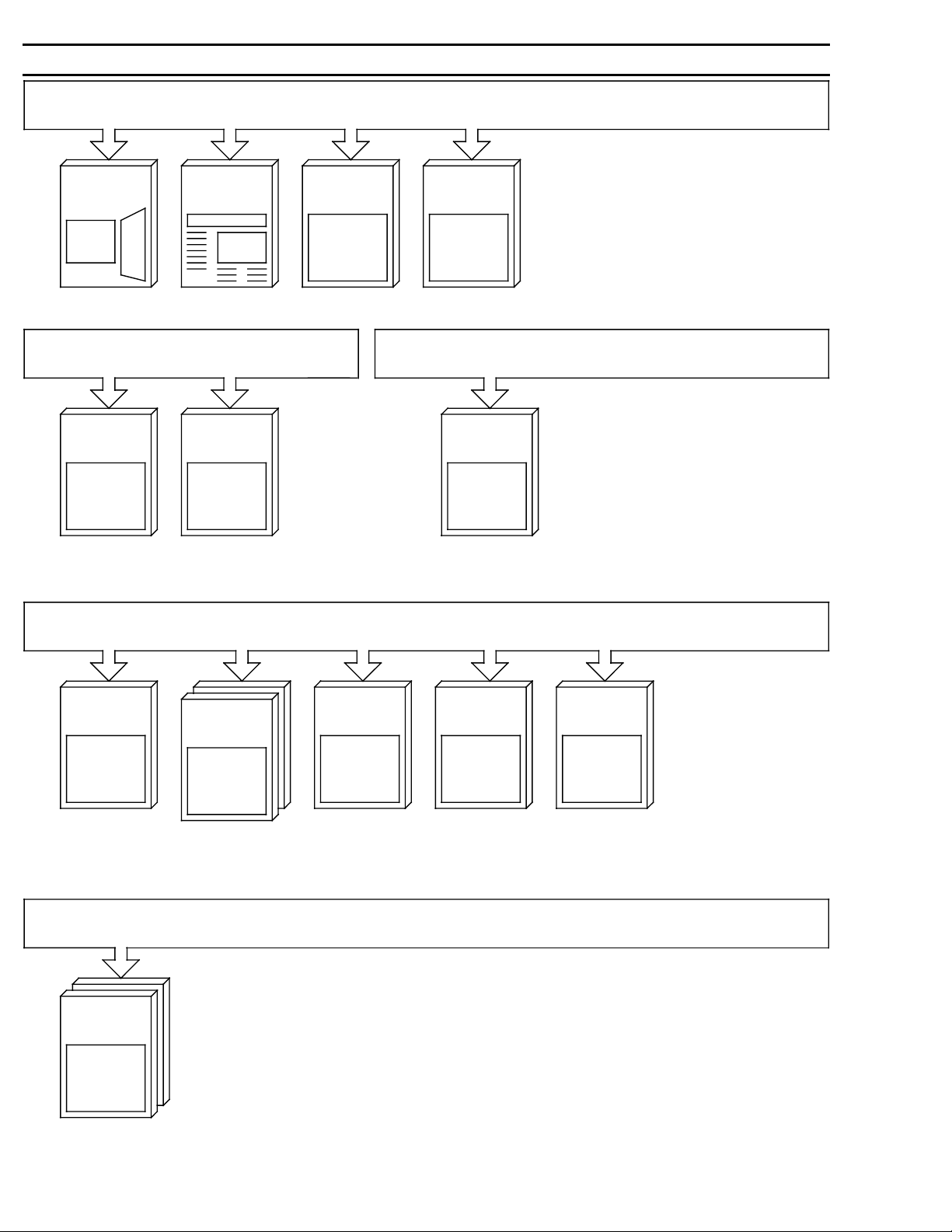
General Documentation
SINUMERIK 805
SINUMERIK
805
Sales Brochure
805
SINUMERIK
Technical Data
User Documentation
805
SINUMERIK
Operator's Guide
805
SINUMERIK
Programming Guide
Manufacturer Documentation
805
SINUMERIK
Catalog NC 34
Accessories
SINUMERIK
Catalog NC 90
User/Manufacturer and Service Documentation
805
SINUMERIK
Function Manual
SINEC L2 Interface Module
805
SINUMERIK
Instruction Manual
805
SINUMERIK
Interface:
- Signals
- Cables and
Connections
Service Documentation
805
SINUMERIK
Installation Guide
- Instructions
- Lists
805
SINUMERIK
PLC Programming
800
SINUMERIK
Universal Interface
800
SINUMERIK
CL 800 Language
Page 5

SINUMERIK 805
Software Version 4
PLC Programming
Planning Guide
Manufacturer Documentation
05.93 Edition
Page 6

SINUMERIK® documentation
Brief details of this edition and previous editions are listed below.
The status of each edition is shown by the code in the ”Remarks” column.
Status code in
”Remarks”
column
:
A . . . New documentation
B . . . Unrevised reprint with new Order No.
C . . . Revised edition with new status. If factual changes have been made on a page since
the last edition, this is indicated by a new edition coding in the header on that page.
Edition Order No. Remarks
01.90 6ZB5 410-0CM02-0BA0 A
10.90 6ZB5 410-0CM02-0BA1 C
01.91 6ZB5 410-0CM02-0AA2 C
11.91 6ZB5 410-0CM02-0AA3 C
05.93 6ZB5 410-0CM02-0AN3 Supplement
Other functions not described in this documentation might be
executable in the control. This does not, however, represent an
obligation to supply such functions with a new control or when
servicing.
This publication was produced on the Siemens 5800 Office
System.
Subject to change without prior notice.
The reproduction, transmission or use of this document or its
contents is not permitted without express written authority.
Offenders will be liable for damages. All rights, including rights
created by patent grant or registration of a utility model or
design, are reserved.
Siemens AG 1990 All Rights Reserved
©
Page 7

1Introduction
Organization, Program and Sequence Blocks
Data Blocks
Function Blocks 4
Program Organization
2
3
5
6Integral Function Blocks
Transfer Parameters and Operating System Machine
7
8Error Analysis
9STEP 5 Command Set with Programming Examples
10Rules of Compatibility between LAD, CSF and STL
Page 8

Contents
Page
1 Introductory Remarks . . . . . . . . . . . . . . . . . . . . . . . . . . . . . . . . . . . 1-1
1.1 Application, memory capacity . . . . . . . . . . . . . . . . . . . . . . . . . . . . . . 1-1
1.2 STEP 5 programming language . . . . . . . . . . . . . . . . . . . . . . . . . . . . . 1-2
1.3 Programming . . . . . . . . . . . . . . . . . . . . . . . . . . . . . . . . . . . . . . . . . . 1-3
1.3.1 Program structure . . . . . . . . . . . . . . . . . . . . . . . . . . . . . . . . . . . . . . 1-3
1.3.2 Program organization . . . . . . . . . . . . . . . . . . . . . . . . . . . . . . . . . . . . 1-4
1.3.3 Program scanning . . . . . . . . . . . . . . . . . . . . . . . . . . . . . . . . . . . . . . 1-5
1.3.4 Influencing factor: User program size . . . . . . . . . . . . . . . . . . . . . . . . . 1-6
2 Organization, Program and Sequence Blocks . . . . . . . . . . . . . . . . 2-1
2.1 Programming program blocks . . . . . . . . . . . . . . . . . . . . . . . . . . . . . . 2-1
2.2 Calling program blocks . . . . . . . . . . . . . . . . . . . . . . . . . . . . . . . . . . . 2-2
3 Data Blocks . . . . . . . . . . . . . . . . . . . . . . . . . . . . . . . . . . . . . . . . . 3-1
3.1 Programming data blocks . . . . . . . . . . . . . . . . . . . . . . . . . . . . . . . . . 3-1
3.2 Calling data blocks . . . . . . . . . . . . . . . . . . . . . . . . . . . . . . . . . . . . . . 3-2
3.3 Data blocks created by the operating system . . . . . . . . . . . . . . . . . . . 3-4
4 Function Blocks . . . . . . . . . . . . . . . . . . . . . . . . . . . . . . . . . . . . . . 4-1
4.1 General remarks . . . . . . . . . . . . . . . . . . . . . . . . . . . . . . . . . . . . . . . 4-1
4.2 Structure of function blocks . . . . . . . . . . . . . . . . . . . . . . . . . . . . . . . . 4-2
4.2.1 Block header . . . . . . . . . . . . . . . . . . . . . . . . . . . . . . . . . . . . . . . . . . 4-2
4.2.2 Block body . . . . . . . . . . . . . . . . . . . . . . . . . . . . . . . . . . . . . . . . . . . 4-2
4.3 Calling and initializing function blocks . . . . . . . . . . . . . . . . . . . . . . . . . 4-3
4.3.1 Call statement . . . . . . . . . . . . . . . . . . . . . . . . . . . . . . . . . . . . . . . . . 4-3
4.3.2 Parameter list . . . . . . . . . . . . . . . . . . . . . . . . . . . . . . . . . . . . . . . . . . 4-3
4.4 Programming function blocks . . . . . . . . . . . . . . . . . . . . . . . . . . . . . . . 4-4
4.4.1 Library number . . . . . . . . . . . . . . . . . . . . . . . . . . . . . . . . . . . . . . . . . 4-4
4.4.2 Name of the function block . . . . . . . . . . . . . . . . . . . . . . . . . . . . . . . . 4-4
4.4.3 Formal operand (block parameter name) . . . . . . . . . . . . . . . . . . . . . . . 4-5
4.4.4 Block parameter types . . . . . . . . . . . . . . . . . . . . . . . . . . . . . . . . . . . 4-6
4.4.5 Block parameters and permitted actual parameters . . . . . . . . . . . . . . . 4-7
5 Program Organization . . . . . . . . . . . . . . . . . . . . . . . . . . . . . . . . . . 5-1
5.1 General remarks . . . . . . . . . . . . . . . . . . . . . . . . . . . . . . . . . . . . . . . 5-1
5.2 Cyclic scanning . . . . . . . . . . . . . . . . . . . . . . . . . . . . . . . . . . . . . . . . 5-2
5.2.1 Interrupt capability . . . . . . . . . . . . . . . . . . . . . . . . . . . . . . . . . . . . . . 5-2
5.2.2 Response time and cycle time . . . . . . . . . . . . . . . . . . . . . . . . . . . . . . 5-3
5.2.3 Programming the cyclic program . . . . . . . . . . . . . . . . . . . . . . . . . . . . 5-3
5.2.4 Interface between operating system and cyclic program . . . . . . . . . . . . 5-4
5.2.5 Basic program organization . . . . . . . . . . . . . . . . . . . . . . . . . . . . . . . . 5-5
5.3 Interrupt processing . . . . . . . . . . . . . . . . . . . . . . . . . . . . . . . . . . . . . 5-7
5.3.1 Programming the interrupt service routine . . . . . . . . . . . . . . . . . . . . . . 5-7
5.3.2 Interface between operating system and the interrupt . . . . . . . . . . . . . . 5-7
5.3.3 Response time . . . . . . . . . . . . . . . . . . . . . . . . . . . . . . . . . . . . . . . . . 5-8
Page 9

6 Integral Function Blocks . . . . . . . . . . . . . . . . . . . . . . . . . . . . . . . . 6-1
6.1 General remarks . . . . . . . . . . . . . . . . . . . . . . . . . . . . . . . . . . . . . . . . 6-1
6.2 FB identifiers . . . . . . . . . . . . . . . . . . . . . . . . . . . . . . . . . . . . . . . . . . 6-2
6.3 Function macros . . . . . . . . . . . . . . . . . . . . . . . . . . . . . . . . . . . . . . . . 6-3
FB 11 EINR-DB Generate data blocks . . . . . . . . . . . . . . . . . . . . 6-4
FB 60 BLOCK-TR Block transfer . . . . . . . . . . . . . . . . . . . . . . . . . 6-6
FB 61 NCD-LESE Read NC data
FB 62 NCD-SCHR Write NC data . . . . . . . . . . . . . . . . . . . . . . . . . 6-8
FB 65 M STACK Transfer flags to stack . . . . . . . . . . . . . . . . . . . 6-18
FB 66 STACK M Flag stack to transfer flag area . . . . . . . . . . . . . 6-18
7 Transfer Parameters and Operating System Machine Data . . . . . . 7-1
7.1 Transfer parameters . . . . . . . . . . . . . . . . . . . . . . . . . . . . . . . . . . . . . 7-1
7.2 PLC machine data SINUMERIK 805 . . . . . . . . . . . . . . . . . . . . . . . . . . 7-4
7.3 PLC machine data bits SINUMERIK 805 . . . . . . . . . . . . . . . . . . . . . . . 7-5
8 Error Analysis . . . . . . . . . . . . . . . . . . . . . . . . . . . . . . . . . . . . . . . . . 8-1
8.1 Types of error . . . . . . . . . . . . . . . . . . . . . . . . . . . . . . . . . . . . . . . . . 8-1
8.2 Interrupt stack . . . . . . . . . . . . . . . . . . . . . . . . . . . . . . . . . . . . . . . . . 8-3
8.3 Detailed error code . . . . . . . . . . . . . . . . . . . . . . . . . . . . . . . . . . . . . . 8-5
8.3.1 Display on programmer . . . . . . . . . . . . . . . . . . . . . . . . . . . . . . . . . . . 8-5
8.3.2 Display on NC screen . . . . . . . . . . . . . . . . . . . . . . . . . . . . . . . . . . . . 8-6
8.4 Alarm List . . . . . . . . . . . . . . . . . . . . . . . . . . . . . . . . . . . . . . . . . . . . 8-7
9 STEP 5 Command Set with Programming Examples . . . . . . . . . . . . 9-1
9.1 Memory organization . . . . . . . . . . . . . . . . . . . . . . . . . . . . . . . . . . . . . 9-1
9.1.1 Changing the segment switch . . . . . . . . . . . . . . . . . . . . . . . . . . . . . . 9-3
9.1.2 Block lists . . . . . . . . . . . . . . . . . . . . . . . . . . . . . . . . . . . . . . . . . . . . 9-3
9.2 General notes . . . . . . . . . . . . . . . . . . . . . . . . . . . . . . . . . . . . . . . . . 9-6
9.2.1 Numeric representation . . . . . . . . . . . . . . . . . . . . . . . . . . . . . . . . . . . 9-6
9.2.2 Condition codes of the PLC . . . . . . . . . . . . . . . . . . . . . . . . . . . . . . . . 9-8
9.2.3 STEP 5 command representation . . . . . . . . . . . . . . . . . . . . . . . . . . . . 9-9
9.3 Basic operations . . . . . . . . . . . . . . . . . . . . . . . . . . . . . . . . . . . . . . . . 9-11
9.3.1 Logic operations, binary . . . . . . . . . . . . . . . . . . . . . . . . . . . . . . . . . . 9-11
9.3.2 Storage operations . . . . . . . . . . . . . . . . . . . . . . . . . . . . . . . . . . . . . . 9-14
9.3.3 Load and transfer operations . . . . . . . . . . . . . . . . . . . . . . . . . . . . . . . 9-17
9.3.4 Timing and counting operations . . . . . . . . . . . . . . . . . . . . . . . . . . . . . 9-19
9.3.5 Comparison operations . . . . . . . . . . . . . . . . . . . . . . . . . . . . . . . . . . . 9-27
9.3.6 Block calls . . . . . . . . . . . . . . . . . . . . . . . . . . . . . . . . . . . . . . . . . . . . 9-31
9.3.7 Code operations . . . . . . . . . . . . . . . . . . . . . . . . . . . . . . . . . . . . . . . . 9-33
9.3.8 Arithmetic operations . . . . . . . . . . . . . . . . . . . . . . . . . . . . . . . . . . . . 9-34
9.3.9 Other operations . . . . . . . . . . . . . . . . . . . . . . . . . . . . . . . . . . . . . . . . 9-35
9.4 Supplementary operations (with function blocks only) . . . . . . . . . . . . . . 9-34
9.4.1 Logic operations, binary . . . . . . . . . . . . . . . . . . . . . . . . . . . . . . . . . . 9-35
9.4.2 Setting operations . . . . . . . . . . . . . . . . . . . . . . . . . . . . . . . . . . . . . . . 9-35
9.4.3 Timing and counting operations . . . . . . . . . . . . . . . . . . . . . . . . . . . . . 9-36
9.4.4 Enabling operations for timing and counting operations . . . . . . . . . . . . . 9-38
Page 10

9.4.5 Bit test operations (with function blocks only) . . . . . . . . . . . . . . . . . . . 9-39
9.4.6 Coding, load and transfer operations . . . . . . . . . . . . . . . . . . . . . . . . . 9-40
9.4.7 Logic operations, digital . . . . . . . . . . . . . . . . . . . . . . . . . . . . . . . . . . 9-41
9.4.8 Shift operations . . . . . . . . . . . . . . . . . . . . . . . . . . . . . . . . . . . . . . . . 9-41
9.4.9 Conversion operations . . . . . . . . . . . . . . . . . . . . . . . . . . . . . . . . . . . 9-42
9.4.10 Decrementing / Incrementing . . . . . . . . . . . . . . . . . . . . . . . . . . . . . . . 9-42
9.4.11 Jump operations . . . . . . . . . . . . . . . . . . . . . . . . . . . . . . . . . . . . . . . 9-43
9.4.12 Processing operations . . . . . . . . . . . . . . . . . . . . . . . . . . . . . . . . . . . . 9-46
9.4.13 STEP 5 commands with direct memory access . . . . . . . . . . . . . . . . . . 9-48
9.4.14 Other operations . . . . . . . . . . . . . . . . . . . . . . . . . . . . . . . . . . . . . . . 9-49
9.5 Command Set with Programming Examples . . . . . . . . . . . . . . . . . . . . 9-50
10 Rules of Compatibility between the LAD, CSF and
STL Methods of Representation . . . . . . . . . . . . . . . . . . . . . . . . . . . 10-1
10.1 General . . . . . . . . . . . . . . . . . . . . . . . . . . . . . . . . . . . . . . . . . . . . . . 10-1
10.2 Rules of compatibility for graphic program input
(LAD, CSF) . . . . . . . . . . . . . . . . . . . . . . . . . . . . . . . . . . . . . . . . . . . 10-2
10.3 Rules of compatibility for program input in a statement list . . . . . . . . . . 10-4
Page 11
Preliminary Remarks
aaaaaaaaaaaaaaaaaaaaaaaaaaaaaaaaaaaaaaaaaaa
a
a
a
a
a
a
a
a
a
a
a
a
a
a
a
a
a
a
a
aaaaaaaaaaaaaaaaaaaaaaaaaaaaaaaaaaaaaaaaaaaaaaaaaaa
a
a
a
a
a
a
a
a
a
a
a
a
a
a
a
a
a
aaaaaaaaaaaaaaaaaaaaaaaaaaaaaaaaaaaaaaaaaaaaaaaaaaaaaaaaaaaaaaaaaaaaaaaaaaaaaaaaaaaaaaaaaaaaaaaaaaaaaaaaaaaaaaa
a
a
a
a
a
a
a
a
a
a
a
a
a
a
a
a
a
a
a
a
a
a
a
a
a
a
a
a
a
a
a
a
a
a
a
a
a
aaaaaaaaaaaaaaaaaaaaaaaaaaaaaaaaaaaaaaaaaaaaaaaaaaaaaaaaaaaaaaaaaaaaaaaaaaaaaaaaaaaaaaaaaaaaaaaaaaa
a
a
a
a
a
a
a
a
a
a
a
a
a
a
a
a
a
a
a
a
a
a
a
a
a
a
a
a
a
a
aaaaaaaaaaaaaaaaaaaaaaaaaaaaaaaaaaaaaaaaa
aaaaaaaaaaaaaaaaaaaaaaaaaaaaaaaaaaaaaaaaa
aaaaaaaaaaaaaaaaaaaaaaaaaaaaaaaaaaaaaaaaa
aaaaaaaaaaaaaaaaaaaaaaaaaaaaaaaaaaaaaaaaa
aaaaaaaaaaaaaaaaaaaaaaaaaaaaaaaaaaaaaaaaa
aaaaaaaaaaaaaaaaaaaaaaaaaaaaaaaaaaaaaaaaa
Notes for the reader
aaaaaaaaaaaaaaaaaaaaaaaaaaaaaaaaaaaaaaaaa
aaaaaaaaaaaaaaaaaaaaaaaaaaaaaaaaaaaaaaaaa
aaaaaaaaaaaaaaaaaaaaaaaaaaaaaaaaaaaaaaaaa
a
a
a
a
a
a
a
a
a
This manual is intended for the manufacturers of machine tools using SINUMERIK 805.
The Guide describes the program structure and the operation set of the PLC, and explains
how basic PLC software and user programs, which comprise data blocks, function blocks,
program blocks and organization blocks, are constructed.
The SINUMERIK documentation is organized in three levels:
• User documentation
• Manufacturer documentation and
• Service documentation
The Manufacturer Documentation for SINUMERIK 805 is divided into the following:
• Instruction Manual
• Description of interfaces
Part 1: Signals
Part 2: Cables and hardware
• PLC Programming
Additional SINUMERIK publications are also available for all SINUMERIK controls (e. g.
publications on the Universal Interface, Measuring Cycles, CL 800 Cycles language).
Please contact your Siemens regional office for further details.
aaaaaaaaaaaaaaaaaaaaaaaaaaaaaaaaaaaaaaaaaaaaaaaaa
aaaaaaaaaaaaaaaaaaaaaaaaaaaaaaaaaaaaaaaaaaaaaaaaa
aaaaaaaaaaaaaaaaaaaaaaaaaaaaaaaaaaaaaaaaaaaaaaaaa
aaaaaaaaaaaaaaaaaaaaaaaaaaaaaaaaaaaaaaaaaaaaaaaaa
aaaaaaaaaaaaaaaaaaaaaaaaaaaaaaaaaaaaaaaaaaaaaaaaa
aaaaaaaaaaaaaaaaaaaaaaaaaaaaaaaaaaaaaaaaaaaaaaaaa
aaaaaaaaaaaaaaaaaaaaaaaaaaaaaaaaaaaaaaaaaaaaaaaaa
aaaaaaaaaaaaaaaaaaaaaaaaaaaaaaaaaaaaaaaaaaaaaaaaa
aaaaaaaaaaaaaaaaaaaaaaaaaaaaaaaaaaaaaaaaaaaaaaaaaaaaaaaaaaaaaaaaaaaaaaaaaaaaaaaaaaaaaaaaaaaaaaaaaaaaaaaaaaaaa
aaaaaaaaaaaaaaaaaaaaaaaaaaaaaaaaaaaaaaaaaaaaaaaaaaaaaaaaaaaaaaaaaaaaaaaaaaaaaaaaaaaaaaaaaaaaaaaaaaaaaaaaaaaaa
aaaaaaaaaaaaaaaaaaaaaaaaaaaaaaaaaaaaaaaaaaaaaaaaaaaaaaaaaaaaaaaaaaaaaaaaaaaaaaaaaaaaaaaaaaaaaaaaaaaaaaaaaaaaa
aaaaaaaaaaaaaaaaaaaaaaaaaaaaaaaaaaaaaaaaaaaaaaaaaaaaaaaaaaaaaaaaaaaaaaaaaaaaaaaaaaaaaaaaaaaaaaaaaaaaaaaaaaaaa
aaaaaaaaaaaaaaaaaaaaaaaaaaaaaaaaaaaaaaaaaaaaaaaaaaaaaaaaaaaaaaaaaaaaaaaaaaaaaaaaaaaaaaaaaaaaaaaaaaaaaaaaaaaaa
aaaaaaaaaaaaaaaaaaaaaaaaaaaaaaaaaaaaaaaaaaaaaaaaaaaaaaaaaaaaaaaaaaaaaaaaaaaaaaaaaaaaaaaaaaaaaaaaaaaaaaaaaaaaa
aaaaaaaaaaaaaaaaaaaaaaaaaaaaaaaaaaaaaaaaaaaaaaaaaaaaaaaaaaaaaaaaaaaaaaaaaaaaaaaaaaaaaaaaaaaaaaaaaaaaaaaaaaaaa
aaaaaaaaaaaaaaaaaaaaaaaaaaaaaaaaaaaaaaaaaaaaaaaaaaaaaaaaaaaaaaaaaaaaaaaaaaaaaaaaaaaaaaaaaaaaaaaaaaaaaaaaaaaaa
aaaaaaaaaaaaaaaaaaaaaaaaaaaaaaaaaaaaaaaaaaaaaaaaaaaaaaaaaaaaaaaaaaaaaaaaaaaaaaaaaaaaaaaaaaaaaaaaaaaaaaaaaaaaa
aaaaaaaaaaaaaaaaaaaaaaaaaaaaaaaaaaaaaaaaaaaaaaaaaaaaaaaaaaaaaaaaaaaaaaaaaaaaaaaaaaaaaaaaaaaaaaaaaaaaaaaaaaaaa
aaaaaaaaaaaaaaaaaaaaaaaaaaaaaaaaaaaaaaaaaaaaaaaaaaaaaaaaaaaaaaaaaaaaaaaaaaaaaaaaaaaaaaaaaaaaaaaaaaaaaaaaaaaaa
aaaaaaaaaaaaaaaaaaaaaaaaaaaaaaaaaaaaaaaaaaaaaaaaaaaaaaaaaaaaaaaaaaaaaaaaaaaaaaaaaaaaaaaaaaaaaaaaaaaaaaaaaaaaa
aaaaaaaaaaaaaaaaaaaaaaaaaaaaaaaaaaaaaaaaaaaaaaaaaaaaaaaaaaaaaaaaaaaaaaaaaaaaaaaaaaaaaaaaaaaaaaaaaaaaaaaaaaaaa
aaaaaaaaaaaaaaaaaaaaaaaaaaaaaaaaaaaaaaaaaaaaaaaaaaaaaaaaaaaaaaaaaaaaaaaaaaaaaaaaaaaaaaaaaaaaaaaaaaaaaaaaaaaaa
aaaaaaaaaaaaaaaaaaaaaaaaaaaaaaaaaaaaaaaaaaaaaaaaaaaaaaaaaaaaaaaaaaaaaaaaaaaaaaaaaaaaaaaaaaaaaaaaaaaaaaaaaaaaa
aaaaaaaaaaaaaaaaaaaaaaaaaaaaaaaaaaaaaaaaaaaaaaaaaaaaaaaaaaaaaaaaaaaaaaaaaaaaaaaaaaaaaaaaaaaaaaaaaaaaaaaaaaaaa
aaaaaaaaaaaaaaaaaaaaaaaaaaaaaaaaaaaaaaaaaaaaaaaaaaaaaaaaaaaaaaaaaaaaaaaaaaaaaaaaaaaaaaaaaaaaaaaaaaaaaaaaaaaaa
aaaaaaaaaaaaaaaaaaaaaaaaaaaaaaaaaaaaaaaaaaaaaaaaaaaaaaaaaaaaaaaaaaaaaaaaaaaaaaaaaaaaaaaaaaaaaaaaaaaaaaaaaaaaa
Technical information
aaaaaaaaaaaaaaaaaaaaaaaaaaaaaaaaaaaaaaaaaaaaaaaaaaaaaaaaaaaaaaaaaaaaaaaaaaaaaaaaaaaaaaaaaaaaaaaaa
aaaaaaaaaaaaaaaaaaaaaaaaaaaaaaaaaaaaaaaaaaaaaaaaaaaaaaaaaaaaaaaaaaaaaaaaaaaaaaaaaaaaaaaaaaaaaaaaa
aaaaaaaaaaaaaaaaaaaaaaaaaaaaaaaaaaaaaaaaaaaaaaaaaaaaaaaaaaaaaaaaaaaaaaaaaaaaaaaaaaaaaaaaaaaaaaaaa
aaaaaaaaaaaaaaaaaaaaaaaaaaaaaaaaaaaaaaaaaaaaaaaaaaaaaaaaaaaaaaaaaaaaaaaaaaaaaaaaaaaaaaaaaaaaaaaaa
aaaaaaaaaaaaaaaaaaaaaaaaaaaaaaaaaaaaaaaaaaaaaaaaaaaaaaaaaaaaaaaaaaaaaaaaaaaaaaaaaaaaaaaaaaaaaaaaa
aaaaaaaaaaaaaaaaaaaaaaaaaaaaaaaaaaaaaaaaaaaaaaaaaaaaaaaaaaaaaaaaaaaaaaaaaaaaaaaaaaaaaaaaaaaaaaaaa
aaaaaaaaaaaaaaaaaaaaaaaaaaaaaaaaaaaaaaaaaaaaaaaaaaaaaaaaaaaaaaaaaaaaaaaaaaaaaaaaaaaaaaaaaaaaaaaaa
aaaaaaaaaaaaaaaaaaaaaaaaaaaaaaaaaaaaaaaaaaaaaaaaaaaaaaaaaaaaaaaaaaaaaaaaaaaaaaaaaaaaaaaaaaaaaaaaa
aaaaaaaaaaaaaaaaaaaaaaaaaaaaaaaaaaaaaaaaaaaaaaaaaaaaaaaaaaaaaaaaaaaaaaaaaaaaaaaaaaaaaaaaaaaaaaaaa
aaaaaaaaaaaaaaaaaaaaaaaaaaaaaaaaaaaaaaaaaaaaaaaaaaaaaaaaaaaaaaaaaaaaaaaaaaaaaaaaaaaaaaaaaaaaaaaaa
aaaaaaaaaaaaaaaaaaaaaaaaaaaaaaaaaaaaaaaaaaaaaaaaaaaaaaaaaaaaaaaaaaaaaaaaaaaaaaaaaaaaaaaaaaaaaaaaa
aaaaaaaaaaaaaaaaaaaaaaaaaaaaaaaaaaaaaaaaaaaaaaaaaaaaaaaaaaaaaaaaaaaaaaaaaaaaaaaaaaaaaaaaaaaaaaaaa
aaaaaaaaaaaaaaaaaaaaaaaaaaaaaaaaaaaaaaaaaaaaaaaaaaaaaaaaaaaaaaaaaaaaaaaaaaaaaaaaaaaaaaaaaaaaaaaaa
aaaaaaaaaaaaaaaaaaaaaaaaaaaaaaaaaaaaaaaaaaaaaaaaaaaaaaaaaaaaaaaaaaaaaaaaaaaaaaaaaaaaaaaaaaaaaaaaa
aaaaaaaaaaaaaaaaaaaaaaaaaaaaaaaaaaaaaaaaaaaaaaaaaaaaaaaaaaaaaaaaaaaaaaaaaaaaaaaaaaaaaaaaaaaaaaaaa
This documentation applies to software version 4
a
a
a
a
a
a
a
a
a
a
a
a
a
a
a
a
a
a
a
a
a
a
a
a
a
a
Page 12

05.93 1 Introductory Remarks
1.1 Application, memory capacity
1 Introductory Remarks
1.1 Application, memory capacity
The PLC is a powerful interface controller. It has no inherent hardware, and is used as
”software PLC” in the SINUMERIK 805.
The PLC is responsible for control of machine-related functional sequences such as
• Controlling auxiliary axes
• Controlling tool-changers
• Gathering the signals generated by the machine's monitoring devices.
Special features:
On the SINUMERIK 805, all NC and PLC jobs are executed by a common processor
(Intel 80 186). A specially developed coprocessor (COP) is responsible for high-speed execution of binary operations and byte and word commands of the STEP 5 user program (e. g.
A I 3.0, L FW3, etc.).
The single-processor structure calls for strict priority scheduling of NC and PLC jobs. NC functions such as position control and block preparation, but also the PLC ”Interrupt processing”
function (OB 2), have highest priority, while scanning of the cyclic program (OB 1) is of lesser
importance.
The amount of processor time available to the PLC has been restricted to a maximum of 20%
in order to ensure that the NC can fulfill its primary objectives (positioning accuracy, short
block change times) even in extreme situations, e. g. where an exceptionally long STEP 5
program or frequent interrupt servicing is involved. It is also possible to influence the manner
in which the cyclic user program scanned via machine data (see Section 1.3.4).
PLC memory capacity of the SINUMERIK 805
User memory (OB, PB, FB, SB): 8 Kbytes
16 Kbytes (from SW 4.1, Basic Version)
32 Kbytes (from SW 4.1, in Option N46)
Data memory (DB): 4 Kbytes
6 Kbytes (from SW 4.1, Basic Version)
8 Kbytes (from SW 4.1, in Option N46)
Siemens AG 1990 All Rights Reserved 6ZB5 410-0CM02 1–1
©
SINUMERIK 805 (PJ)
Page 13
1 Introductory Remarks 11.91
1.2 STEP 5 programming language
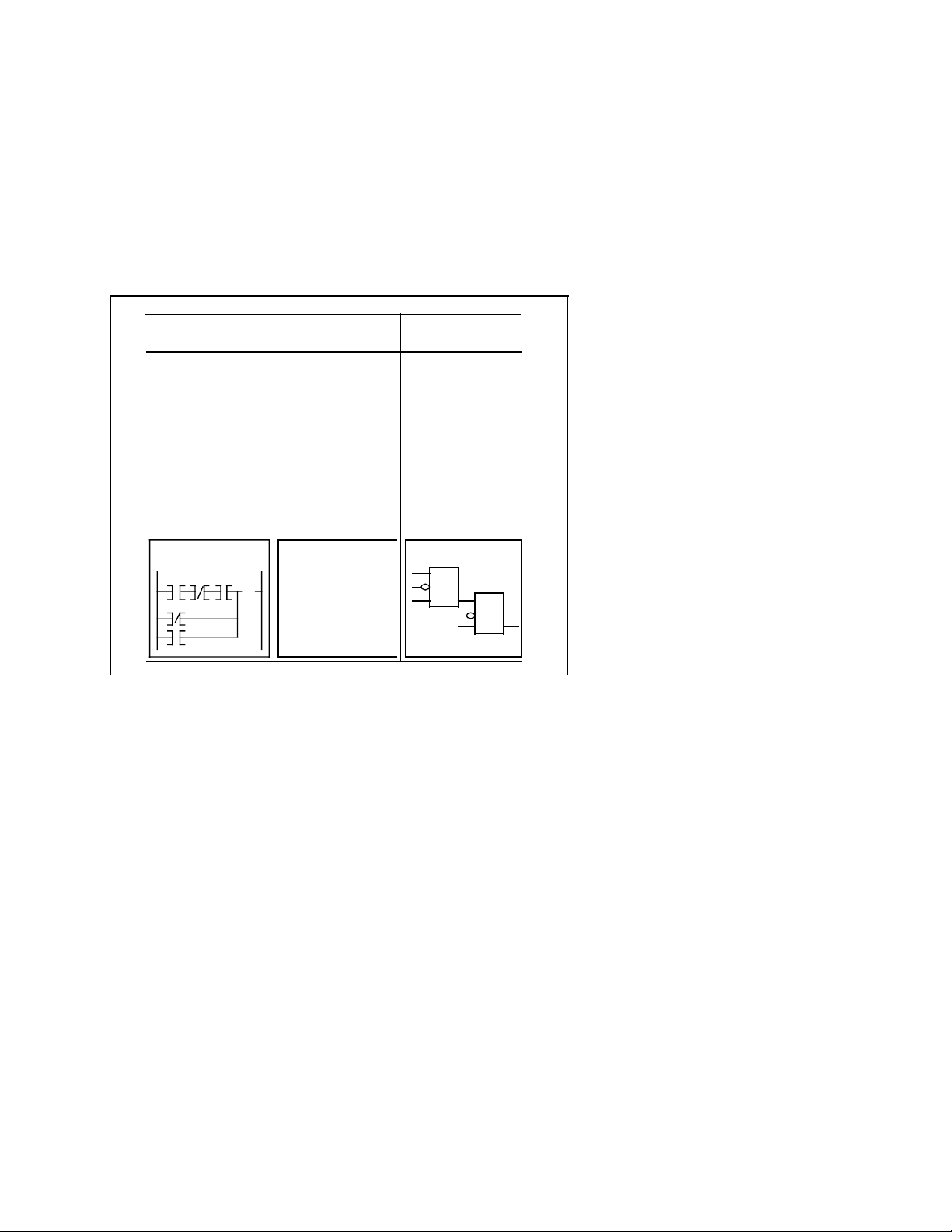
1.2 STEP 5 programming language
The operations available in STEP 5 enable the user to program functions ranging from simple
binary logic to complex digital functions and basic arithmetic operations.
Depending on the programmer (PG) used a STEP 5 program may be written in the form of a
control system flowchart (CSF), ladder diagram (LAD) or statement list (STL) , thus enabling
the programming method to be adapted to the application. The machine code (MC5) generated
by the programmers is identical for all three. Depending on the programmer (PG) used, the
user program can be translated from one method of representation to another by conforming
to certain programming conventions (see Section10).
Ladder diagram Statement list Control system
Programming with Programming with Programming
symbols similar to using mnemonics with graphic
those used in sche- designating symbols
matic circuit dia- functions
grams
Complies with Complies with Complies with
DIN 19239 DIN 19239 IEC 117 - 15
(draft) (draft) DIN 40700
LAD STL
AI
( )
AN I
AI
ON I
OI
=Q
flowchart
DIN 40719
DIN 19239
(draft)
CSF
Methods of representing the STEP 5 programming language
&
>=1
1-2© Siemens AG 1990 All Rights Reserved 6ZB5 410-0CM02
SINUMERIK 805 (PJ)
Page 14

10.90 1 Introductory Remarks
1.3 Programming
1.3 Programming
1.3.1 Program structure
The PLC software comprises the operating system, the basic software and the user program.
The operating system contains all statements and declarations for internal system functions.
The basic software has a flexible interface to the operating basic functions (e. g. generation of
data blocks, NC-PLC interface initialization, signal interchange with the peripherals). The basic
software also contains pretested function blocks written in STEP 5 and assembled to form
function macros.
The operating system and the basic software are integral components of the PLC; they are
supplied on EPROMs together with the NC system program, and may not be modified in any
way.
The user program is the total of all statements and declarations/data programmed by the user.
The PLC structure makes structured programming essential, i. e. the program must be divided
into individual, self-contained sections called blocks. This method offers the following
advantages:
• Easy, lucid programming, even of large programs
• Easy standardization of program sections
• Simple program organization
• Fast, easy modification
• Simple program testing
• Easy start-up
A number of block types, each of which is used for different tasks, is available for structuring
the user program:
• Organization blocks (OBs)
The OBs serve as interface between operating system and user program.
• Program blocks (PBs)
The PBs are used to break the user program down into technologically oriented sections.
• Function blocks (FBs)
The FBs are used to program frequently recurring complex functions (such as individual
controls, reporting, arithmetic and PID control functions).
• Sequence blocks (SBs)
SBs are special forms of program blocks used primarily for processing sequencers.
• Data blocks (DBs)
DBs are used for storing data or texts, and differ in both function and structure from all
other block types.
With the exception of the organization blocks, the maximum number of programmable blocks
of each type is 255. The number of organization blocks may not exceed 64; of these, only OB
20, PB 1 and OB 2 are serviced by the operating system (cf. Section 5).
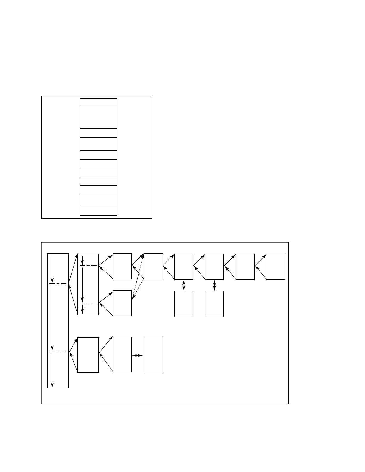
The programmer stores all programmed blocks in arbitrary order in program memory
(Fig. 1.2).
Siemens AG 1990 All Rights Reserved 6ZB5 410-0CM02 1-3
©
SINUMERIK 805 (PJ)
Page 15
1 Introductory Remarks 10.90
1.3.2 Program organization
1.3.2 Program organization
The manner in which the program is organized determines whether and in what order the
program, function and sequence blocks are executed. The order in which these blocks are
involved is stipulated by programming the relevant calls (conditional or unconditional) in
organization blocks (see Section 5.4, ”Cyclic program”).
Like the other blocks, the organization blocks are stored in user memory.
PB1
PB2
•
•
FB1
•
•
DB1
•
SB10
•
FX1
•
•
OB1
Storing the blocks in arbitrary order in program
memory
OB
PB
Different organization blocks are provided for
various methods of program execution (cf.
Section 5.2).
Organization, program, function and
sequence blocks can invoke other program,
function and sequence blocks. The user
program cannot call organization blocks. The
maximum permissible nesting depth for
organization blocks is 12, not including an
accompanying data block, if any.
FBFB
FBFBPBPB
PB
PB
1
Typical program organization in STEP 5 (nesting depth 8) (max. nesting depth 12)
2
3 4
DBFB
DB
5 6 7 8
DB
OB Organization block
PB Program block
FB Function block
DB Data block
1-4© Siemens AG 1990 All Rights Reserved 6ZB5 410-0CM02
SINUMERIK 805 (PJ)
Page 16
05.93 1 Introductory Remarks
1.3.3 Program scanning
1.3.3 Program scanning
The user program can be scanned in three ways:
• One-shot scan
One-shot scan in the controller's restart routine following ”Power up” or ”Hardware reset”.
The statements to be executed must be programmed in OB 20.
• Cyclic scanning
For cyclic scanning 0B1 is available. This block is passed at intervals of 48 ms (up to
SW4.1: 60 ms) and calls the programmed blocks.
• Interrupt scan
Event-driven, one-shot execution of the statements in OB 2, e. g. in response to an
interrupt. Prerequisites for event-driven execution are as follows:
• Normal termination of the controller's restart routine
• Interrupt enable via PLC-MD 2002, bit 0=”0”.
• A change in the interrupt input byte specified per PLC-MD 0.
Cyclic scanning can be interrupted by the high-priority NC functions' interrupt service routine
or delayed pending termination of OB 2 following execution of each STEP 5 command.
Execution of a PLC cycle; cyclic program scanning
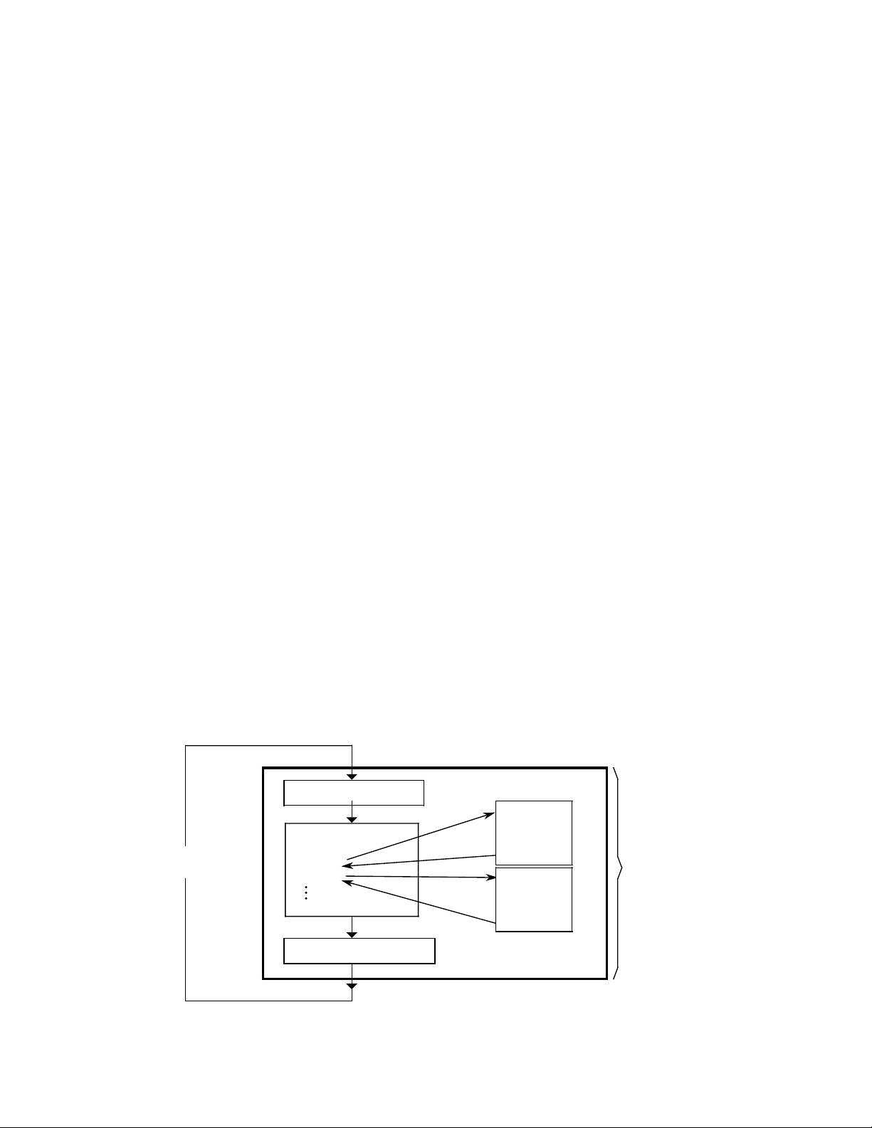
Before OB 1 is called and started, the basic program loads the momentary state of all
peripheral inputs into working memory. All input scans in the cycle which follows refer to this
loaded status image. It is also known as ”Process Input Image” or PII for short.
OB 1 is now called. This executes the blocks that have been called one after the other. This
process can be interrupted by one or several interrupt scans (OB 2).
When OB 1 has been worked through completely, the system program transferss the statuses
of the outputs (resulting from program execution) from the working memory to the peripheral
outputs (MDP submodules, for example).
Load Process Input Image
PB 1
A I 3.1
= Q 2.0
BE
FB 1
A F 0.1
= Q 3.6
BE
PLC cycle
48 (60 )ms
time base
OB 1 scan
OB 1
SPA PB 1
SPA FB 1
BE
Write Process Output Image
© Siemens AG 1990 All Rights Reserved 6ZB5 410-0CM02 1–5
SINUMERIK 805 (PJ)
Page 17

1 Introductory Remarks 05.93
1.3.4 Influencing factor: User program size
1.3.4 Influencing factor: User program size
As mentioned in Section 1.1, execution of the STEP 5 program should not take up more then
15 % of the total available CPU time, nor should the interrupt service routine in OB 2 take up
more time than necessary because of its high priority, as this would delay execution of
important NC functions.
For this purpose, the execution times of both the cyclic user program and the interrupt service
routine are monitored at the hardware level. The permissible runtimes can be set in PLC MD 1
and 3, whereby confirmation of the defaults ensures that the ”integrated PLC” will not take up
more than the admissible amount of CPU time. When these values are exceeded, the PLC
goes to the state specified in bit 0 or 1 of PLC MD 2003; when the defaults are used, the
”integrated PLC” always enters the Stop mode.
When the user programs exceed the permissible execution times only slightly, program
scanning can be upheld by modifying these machine data bits, but this may adversely affect
the NC functions.
There are two ways of ensuring the executability of large cyclic user programs without placing
an excessive load on the CPU:
• Fragmenting cyclic execution through autonomous interrupts
• Allowing cyclic execution to be interrupted by higher-priority program blocks only
The mode is set in PLC MD 2003, bit 6. The percentage in PLC MD thus assumes the
following meaning as regards the scan time:
• No fragmenting (bit 6 of MD 2003 = 0 ˆ= default):
15% of the cyclic program's timing grid (48 ms) results in a permissible runtime of 7.2 ms.
• Fragmenting (bit 6 of MD 2003 = 1)
15% of 1/3 of the cyclic program's timing grid (48 ms) results in a runtime of 2.4 ms. The
cyclic program then interrupts itself autonomously, and resumes execution in the next
third.
–6© Siemens AG 1990 All Rights Reserved 6ZB5 410-0CM02
1
SINUMERIK 805 (PJ)
Page 18
05.93 1 Introductory Remarks
aaaaaaaaaaa
a
a
a
a
a
a
a
a
a
a
a
a
a
a
a
a
a
a
a
aaaaa
a
a
a
a
a
a
a
a
a
aaaaa
a
a
a
a
a
a
a
a
a
aaaaa
a
a
a
a
a
a
a
a
a
aaaaaaa
a
a
a
a
a
a
a
a
a
a
a
a
a
a
a
a
a
a
a
a
a
a
a
a
a
a
a
a
a
a
a
a
a
a
aaaaaaa
a
a
a
a
a
a
a
a
a
a
a
a
a
a
a
a
a
a
a
a
a
a
a
a
a
a
a
a
a
a
a
a
a
a
aaaaaaaaaaaaa
a
a
a
a
a
a
a
a
a
a
a
a
a
a
a
a
a
a
a
a
aaaaaaa
a
a
a
a
a
a
a
a
a
a
a
a
a
a
a
a
a
a
a
a
a
a
a
a
a
a
a
a
a
a
a
a
a
a
aaaaaaa
a
a
a
a
a
a
a
a
a
a
a
a
a
a
a
a
a
a
a
a
a
a
a
a
a
a
a
a
a
a
a
a
a
a
aaaaaaaaaaa
a
a
a
a
a
a
a
a
a
a
a
a
a
a
a
a
a
a
a
a
a
a
a
aaaaa
a
a
a
a
a
a
a
a
a
a
a
a
a
a
a
a
a
a
a
a
a
a
a
a
a
a
a
a
a
a
a
a
a
a
a
aaaaa
a
a
a
a
a
a
a
a
a
a
a
a
a
a
a
a
a
a
a
a
a
a
a
a
a
a
a
a
a
a
a
a
a
a
a
aaaaaaa
a
a
a
a
a
a
a
a
a
a
a
a
a
a
a
a
a
a
a
a
a
a
a
aaaaaaa
a
a
a
a
a
a
a
a
a
a
a
a
a
a
a
a
a
a
a
a
a
a
a
a
a
a
a
a
a
a
a
a
a
a
aaaaaaa
a
a
a
a
a
a
a
a
a
a
a
a
a
a
a
a
a
a
a
a
a
a
a
a
a
a
a
a
a
a
a
a
a
a
aaaaaaa
aaaaaaa
aaaaaaa
aaaaaaa
aaaaaaa
aaaaaaa
aaaaaaa
aaaaaaa
aaaaaaa
aaaaaaa
aaaaaaa
aaaaaaa
aaaaaaa
aaaaaaa
aaaaaaa
aaaaaaa
aaaaaaa
aaaaaaa
aaaaaaa
aaaaaaa
aaaaaaa
aaaaaaa
aaaaaaa
aaaaaaa
aaaaaaa
aaaaaaa
aaaaaaa
aaaaaaa
aaaaaaa
aaaaaaa
aaaaaaa
aaaaaaa
aaaaaaa
aaaaaaa
aaaaaaa
aaaaaaa
aaaaa
aaaaa
aaaaa
aaaaa
aaaaa
aaaaa
aaaaa
aaaaa
aaaaa
aaaaa
aaaaa
aaaaa
aaaaaaaaaaaaaaaaaaaaaaaaaaaaaaaaaaa
a
a
a
a
a
a
a
a
a
a
a
a
a
a
a
a
aaaaaaa
a
a
a
a
a
a
a
a
a
a
a
a
a
a
a
a
a
a
a
a
a
a
a
a
a
a
a
a
a
a
a
a
a
a
aaaaaaa
a
a
a
a
a
a
a
a
a
a
a
a
a
a
a
a
a
a
a
a
a
a
a
a
a
a
a
a
a
a
a
a
a
a
aaaaa
a
a
a
a
a
a
a
a
a
a
a
a
a
a
a
a
a
a
a
a
a
a
a
a
a
a
a
a
a
a
a
a
a
a
a
a
a
aaaaa
a
a
a
a
a
a
a
a
a
a
a
a
a
a
a
a
a
a
a
a
a
a
a
a
a
a
a
a
a
a
a
a
a
a
a
a
a
aaaaaaa
aaaaaaa
aaaaaaa
aaaaaaa
aaaaaaa
aaaaaaa
aaaaaaa
aaaaaaa
aaaaaaa
aaaaaaa
aaaaaaa
aaaaaaa
aaaaaaa
a
a
a
a
a
a
a
a
a
a
a
a
a
a
a
a
a
a
a
a
a
a
a
a
a
a
a
a
a
a
a
a
a
a
a
a
aaaaaaa
a
a
a
a
a
a
a
a
a
a
a
a
a
a
a
a
a
a
a
a
a
a
a
a
a
a
a
a
a
a
a
a
a
a
a
a
aaaaaaa
a
a
a
a
a
a
a
a
a
a
a
a
a
a
a
a
a
a
a
a
a
a
aaaaaaa
a
a
a
a
a
a
a
a
a
a
a
a
a
a
a
a
a
a
a
a
a
a
a
a
a
a
a
a
a
a
a
a
a
a
a
a
aaaaaaa
a
a
a
a
a
a
a
a
a
a
a
a
a
a
a
a
a
a
a
a
a
a
a
a
a
a
a
a
a
a
a
a
a
a
a
a
aaaaa
a
a
a
a
a
a
a
a
a
a
a
a
a
a
a
a
a
a
a
a
a
a
a
a
a
a
a
a
a
a
a
a
a
a
a
a
a
aaaaa
a
a
a
a
a
a
a
a
a
a
a
a
a
a
a
a
a
a
a
a
a
a
a
a
a
a
a
a
a
a
a
a
a
a
a
a
a
aaaaa
a
aaaaa
a
aaaaa
a
aaaaa
a
aaaaa
a
aaaaa
a
aaaaa
a
aaaaa
a
aaaaa
a
aaaaa
a
aaaaa
a
aaaaa
a
aaaaa
a
aaaaaaa
a
aaaaaaa
a
aaaaaaa
a
aaaaaaa
a
aaaaaaa
a
aaaaaaa
a
aaaaaaa
a
aaaaaaa
a
aaaaaaa
a
aaaaaaa
a
aaaaaaa
a
aaaaaaa
a
aaaaaaa
a
a
a
a
a
a
a
a
a
a
a
a
a
a
a
a
a
a
a
a
a
a
a
a
a
a
a
a
a
a
a
a
a
a
aaaaaaa
a
a
a
a
a
a
a
a
a
a
a
a
a
a
a
a
a
a
a
a
a
a
a
a
a
a
a
a
a
a
a
a
a
a
aaaaaaa
aaaaaaa
aaaaaaa
aaaaaaa
aaaaaaa
aaaaaaa
aaaaaaa
aaaaaaa
aaaaaaa
aaaaaaa
aaaaaaa
aaaaaaa
aaaaaaaaaaaaaaaaaaaaaaaaaaaaaaaaaaaaaaaaaaaaaaaaaaaaaaaaaaaaaaaaaaaaaaaaaaaaaaa
a
a
a
a
a
a
a
a
a
a
a
1.3.4 Influencing factor: User program size
Grafic overview of the two methods for cyclic program scanning
Note: OB 1 (cyclical user program) can only be called up in the 48 ms grid (up to SW 4.1:
60 ms).
Priority
Priority
No fragmenting
aaaaa
aaaaa
aaaaa
aaaaa
aaaaa
aaaaa
aaaaa
aaaaa
aaaaa
aaaaa
aaaaa
aaaaa
aaaaa
aaaaa
aaaaaaaaa
aaaaa
aaaaa
aaaaaaaaa
aaaaa
aaaaa
aaaaaaaaa
aaaaa
aaaaa
aaaaaaaaa
aaaaa
aaaaa
aaaaaaaaa
aaaaa
aaaaa
aaaaaaaaa
aaaaa
aaaaa
aaaaaaaaa
aaaaa
aaaaa
aaaaaaaaa
aaaaa
aaaaa
aaaaaaaaa
aaaaa
aaaaa
aaaaaaaaa
aaaaa
aaaaa
aaaaaaaaa
0
OB 1
call
Fragmenting
aaa
a
aaa
a
aaa
a
aaa
a
aaa
a
aaa
a
aaa
a
aaa
a
aaa
a
aaa
a
aaa
a
aaa
a
aaa
a
aaa
a
aaaaa
aaa
a
aaa
a
aaaaa
aaa
a
aaa
a
aaaaa
aaa
a
aaa
a
aaaaa
aaa
a
aaa
a
aaaaa
aaa
a
aaa
a
aaaaa
aaa
a
aaa
a
aaaaa
aaa
a
aaa
a
aaaaa
aaa
a
aaa
a
aaaaa
aaa
a
aaa
a
aaaaa
aaa
a
aaa
a
aaaaa
aaa
a
aaa
a
PLC program is executed within the 60 ms grid.
aaaaa
aaaaa
aaaaa
aaaaa
aaaaa
aaaaa
aaaaa
aaaaa
aaaaa
aaaaa
aaaaa
aaaaa
aaaaa
aaaaa
a
aaaaaaaaaaa
aaaaa
aaaaa
a
aaaaaaaaaaa
aaaaa
aaaaa
a
aaaaaaaaaaa
aaaaa
aaaaa
a
aaaaaaaaaaa
aaaaa
aaaaa
a
aaaaaaaaaaa
aaaaa
aaaaa
a
aaaaaaaaaaa
aaaaa
aaaaa
a
aaaaaaaaaaa
aaaaa
aaaaa
a
aaaaaaaaaaa
aaaaa
aaaaa
a
aaaaaaaaaaa
aaaaa
aaaaa
a
aaaaaaaaaaa
aaaaa
aaaaa
a
16 (20) 32 (40)
aaaaaaaaaaaaaaaaaaaaaaaaaaaaaaaaaaaaaaaaaaaaaaaaaaaaaaaaaaaaaaaaaaaaaaaaaaaaa
PLC program could not be executed within the 48 ms (60 ms) time
aaaaaaaaaaaaaaaaaaaaaaaaaaaaaaaaaaaaaaaaaaaaaaaaaaaaaaaaaaaaaaaaaaaaaaaaaaaaa
aaaaaaaaaaaaaaaaaaaaaaaaaaaaaaaaaaaaaaaaaaaaaaaaaaaaaaaaaaaaaaaaaaaaaaaaaaaaa
aaaaaaaaaaaaaaaaaaaaaaaaaaaaaaaaaaaaaaaaaaaaaaaaaaaaaaaaaaaaaaaaaaaaaaaaaaaaa
aaaaaaaaaaaaaaaaaaaaaaaaaaaaaaaaaaaaaaaaaaaaaaaaaaaaaaaaaaaaaaaaaaaaaaaaaaaaa
base and therefore ”Fragmenting” had to be selected.
aaaaa
aaaaa
aaaaa
aaaaa
aaaaa
aaaaa
aaaaa
aaaaa
aaaaa
aaaaa
aaaaa
aaaaa
aaaaa
aaaaa
aaaaa
aaaaa
aaaaa
aaaaa
aaaaa
aaaaa
aaaaa
aaaaa
aaaaa
aaaaa
aaaaa
aaaaa
aaaaa
aaaaa
aaaaa
aaaaa
aaaaa
aaaaa
aaaaa
aaaaa
aaaaa
aaaaa
aaa
aaa
aaa
aaa
aaa
aaa
aaa
aaa
aaa
aaa
aaa
aaa
aaa
aaa
aaa
aaa
aaa
aaa
aaa
aaa
aaa
aaa
aaa
aaa
aaa
aaa
aaa
aaa
aaa
aaa
aaa
aaa
aaa
aaa
aaaaa
aaaaa
aaaaa
aaaaa
aaaaa
aaaaa
aaaaa
aaaaa
aaaaa
aaaaa
aaaaa
aaaaa
aaaaa
aaaaa
aaaaa
aaaaa
aaaaa
aaaaa
aaaaa
aaaaa
aaaaa
aaaaa
aaaaa
aaaaa
aaaaa
aaaaa
aaaaa
aaaaa
aaaaa
aaaaa
aaaaa
aaaaa
aaaaa
aaaaa
aaaaa
aaaaa
a
a
a
a
a
a
a
a
a
a
a
a
a
a
a
a
a
a
a
a
a
a
a
a
a
a
a
a
a
a
a
a
a
a
aaaaa
aaaaa
aaaaa
aaaaa
aaaaa
aaaaa
aaaaa
aaaaa
aaaaa
aaaaa
aaaaa
OB 1
end
a
a
a
a
a
a
a
a
a
a
a
aaaaa
aaaaa
aaaaa
aaaaa
aaaaa
aaaaa
aaaaa
aaaaa
aaaaa
aaaaa
aaaaa
aaaaa
aaaaa
aaaaa
aaaaa
aaaaa
aaaaa
aaaaa
aaaaa
aaaaa
aaaaa
aaaaa
aaaaa
aaaaa
aaaaa
aaaaa
aaaaa
aaaaa
aaaaa
aaaaa
aaaaa
aaaaa
aaaaa
aaaaa
48 (60)
aaa
aaa
aaa
aaa
aaa
aaa
aaa
aaa
aaa
aaa
aaa
aaa
aaa
aaa
aaa
aaa
aaa
aaa
aaa
aaa
aaa
aaa
aaa
aaa
aaa
aaa
aaa
aaa
aaa
aaa
aaa
aaa
aaa
aaa
aaa
aaa
aaaaaaaaa
aaaaaaaaa
aaaaaaaaa
aaaaaaaaa
aaaaaaaaa
aaaaaaaaa
aaaaaaaaa
aaaaaaaaa
aaaaaaaaa
The PLC operating
system (OB 1)
recalls the cyclic user program
a
a
a
a
a
a
a
a
a
a
a
a
a
a
a
a
a
a
a
a
a
a
a
a
a
a
a
a
a
a
a
a
a
a
a
a
a
a
a
a
a
a
a
a
a
aaaaaaaaaaaaaaaaaaaaaaaaaaaaaaaaa
aaaaaaaaaaaaaaaaaaaaaaaaaaaaaaaaa
aaaaaaaaaaaaaaaaaaaaaaaaaaaaaaaaa
aaaaaaaaaaaaaaaaaaaaaaaaaaaaaaaaa
aaaaaaaaaaaaaaaaaaaaaaaaaaaaaaaaa
aaaaaaaaaaaaaaaaaaaaaaaaaaaaaaaaa
aaaaaaaaaaaaaaaaaaaaaaaaaaaaaaaaa
aaaaaaaaaaaaaaaaaaaaaaaaaaaaaaaaa
aaaaa
aaaaa
aaaaa
aaaaa
aaaaa
aaaaa
aaaaa
aaaaa
aaaaa
aaaaa
aaaaa
aaaaa
aaaaa
aaaaa
aaaaa
aaaaa
aaaaa
aaaaa
aaaaa
aaaaa
aaaaa
aaaaa
aaaaa
aaaaa
aaaaa
aaaaa
aaaaa
aaaaa
aaaaa
aaaaa
aaaaa
aaaaa
aaaaa
aaaaa
aaaaa
aaaaa
aaaaa
aaaaa
aaaaa
aaaaa
aaaaa
aaaaa
aaaaa
aaaaa
aaaaa
aaaaa
aaaaa
aaaaa
aaaaa
aaaaa
aaaaa
aaaaa
aaaaa
aaaaa
aaaaa
aaaaa
aaaaa
aaaaa
aaaaa
aaaaa
aaaaa
aaaaa
aaaaa
aaaaa
aaaaa
aaaaa
aaaaa
aaaaa
t/ms
a
a
a
a
a
0
16 (20)
32 (40)
OB 1
call
aaa
a
aaa
a
aaa
a
aaa
a
aaa
a
aaa
a
aaa
aaa
aaa
aaa
aaa
aaa
Higher-priority NC and PLC program blocks
a
a
a
a
a
Cyclic user program scanning (OB 1)
a
Low-priority NC program blocks
If the OB 1 (cyclical useer program) is too large to be processed in the 48 ms (up to SW 4.1:
60 ms) grid, fragmentation must be selected.
Siemens AG 1990 All Rights Reserved 6ZB5 410-0CM02 1–7
©
SINUMERIK 805 (PJ)
48 (60) t/ms
OB 1
64 (80) 96 (120)
end
OB 1
call
Page 19

1 Introductory Remarks 05.93
1.3.4 Influencing factor: User program size
The timing grid,of cyclic program scanning is 12 x the scanning time of the position control
(12 x 4 ms = 48 ms; up to SW 4.1: 12 x 5 = 60 ms).
The admissible execution time of the cyclic program for both variants can also be increased by
augmenting PLC MD 1 (CPU load in %).
The admissible runtime for the interrupt service routine (PLC MD 3), regardless of the cyclic
execution mode, may not exceed 2000 us in an interval of 4 * scanning time (4 x 4 ms =
16 ms; up to SW 4.1: 4 x 5 = 20 ms).
The entire runtime may either be used for one-shot execution of the statements in OB 2 or, in
an extreme situation, for 4-shot execution of OB 2, as the interrupt input byte is scanned for an
edge change on the basis of the scanning time. If the default runtime for OB 2 proves
µ
insufficient, PLC-MD 3 must either be incremented (to max. 2500
s) or the PLC set to the
Stop mode when OB 2 exceeds the allotted time by modifying bit 1 in PLC MD 2003. The
example on the next page emphasizes the difference between the two variants for a cyclic
user program with a runtime time of 25 ms.
No fragmentation:
The cyclic user program may be interrupted by higher-priority NC and PLC program blocks
only ( e. g. position control, interpolation, monitoring functions, programming and test
functions, interrupt service routine (OB 2)). It is otherwise continued until it has terminated and
all signals it generated habe been forwarded to their destinations (NC, I/Os). Only then can the
low-priority functions execute.
Depending on the size of the STEP 5 program in OB 1, the remaining interval may be quite
shorte, as the operating system recalls the cyclic program when 48 ms (up to SW 4.1: 60 ms)
have passed. The consequence is that too little time is available for the low-priority functions, a
fact which becomes immediately apparent in a sluggish ”operator interface”. Display
construction is extremely slow, as is the controller's reaction to keyboard entries. In extreme
situations, the low-priority functions are allatted almost no time at all to execute.
In the example, (runtime of cyclic user program = 25 ms, SW 4.2 installed) the CPU load
caused by the STEP 5 program alone would escalate to value x, where
x =
25 ms
48 ms
.
100 % =
52 % , assuming that cyclic execution
is terminated within 48 ms. In the example, no regard was paid to the 5% basic load resulting
from data transfers prior to and following the OB 1 call.
It is obvious that a CPU load of almost 57% for the controller alone is not acceptable.
–8© Siemens AG 1990 All Rights Reserved 6ZB5 410-0CM02
1
SINUMERIK 805 (PJ)
Page 20

05.93 1 Introductory Remarks
1.3.4 Influencing factor: User program size
Fragmenting:
When this variant is used, the cyclic program interrupts itself autonomously. If the default is
used (values for SW 4.2), the CPU load, referred to the cyclic program timing grid, would be:
x =
2.4 ms . 3
48 ms
.
100 %=15 %
The basic load for the cyclic program, about 5%, must be added to this, so that the cyclic
program load on the CPU would always be 20 %. It is less than 20% when cyclic execution
is not terminated within one timing period. Extremely long cyclic user programs may cause the
cycle time monitor to response (default: 300 ms).
Note:
By selecting the diagnostics function (PLC MD 2003, bit 7 = 1), the user can obtain a general
view of the anticipated run time for STEP 5 programs as well as the required cycle time. On
the basis of these data, he can optimize the configuration of his MD as regards his job
requests and the purpose for which the controller is to be used (cf. section 8 ”Error Analysis”).
Siemens AG 1990 All Rights Reserved 6ZB5 410-0CM02 1–9
©
SINUMERIK 805 (PJ)
Page 21
1 Introductory Remarks 11.91
1.4 Block overview
1.4 Block overview
Organization data blocks
OB No. OB designation OB name
1
2
20
OB for cyclic scanning
OB for interrupt scanning
OB for one-shot scan after starting
Program data blocks
PB No. PB designation PB name
0
User assignable
255
Function data blocks
FB No. FB designation PB name
0
10
11
12
EINR-DB
Reserved
Reserved
Generate data blocks
Reserved
User
assignable
59
60
61
62
63
64
65
66
70
104
105
106
199
200
255
BLOCK-TR
NCD-LESE
NCD-SCHR
M-STACK
STACK-M
SEND
RECEIVE
CONTROL
Reserved
Blocktransfer
Read NC data
Write NC data
Reserved
Reserved
Transfer flags to stack
Flag stack to transfer flag area
Reserved
SINEC L2
Reserved
User assignable
User assignable
1–10 © Siemens AG 1990 All Rights Reserved 6ZB5 410-0CM02
SINUMERIK 805 (PJ)
Page 22

05.93 1 Introductory Remarks
1.4 Block overview
Data blocks
DB No. DB designation DB name
0
1
2
27
28
29
35
36
37
38
70
71
255
Sequence blocks
Address list block
Diagnostics DB
Reserved
Reserved
Interface for analog output (from SW 4.2)
Reserved
Reserved
Interface for data transfer
Interface for serial interface control
Reserved
Reserved
User assignable
User assignable
SB No. SB designation SB name
0
User assignable
255
© Siemens AG 1990 All Rights Reserved 6ZB5 410-0CM02 1–11
SINUMERIK 805 (PJ)
Page 23

01.91 2 Organization, Program and Sequence Blocks
2.1 Programming program blocks
2 Organization, Program and Sequence Blocks
2.1 Programming program blocks
The information presented in this Section applies to the programming of organization (OBs),
program (PBs) and sequence blocks (SBs). These three block types are all programmed in
the same way. Section 3 gives information on programming data blocks and Section 4 information on programming function blocks. Program, organization and sequence blocks can be
programmed in all three STEP 5 modes of representation using the basic operations.
The following description deals with program blocks by way of example.
The first step in programming a program block (PB) is the specification of a program block
number between 0 and 255 (example: PB 25). This is followed by the actual control program,
which is terminated with a ”BE” statement.
An S5 block comprises two parts:
• Block header
• S5 operations (block body)
The block header, which the programmer generates automatically, takes up five words in
program memory.
A program block should always be a self-contained program.
Logical links to other blocks serve no practical purpose.
PB25
Block header
A I 5.7
STEP 5 program
BE
Structure of a program block
© Siemens AG 1990 All Rights Reserved 6ZB5 410-0CM02 2-1
SINUMERIK 805 (PJ)
Page 24
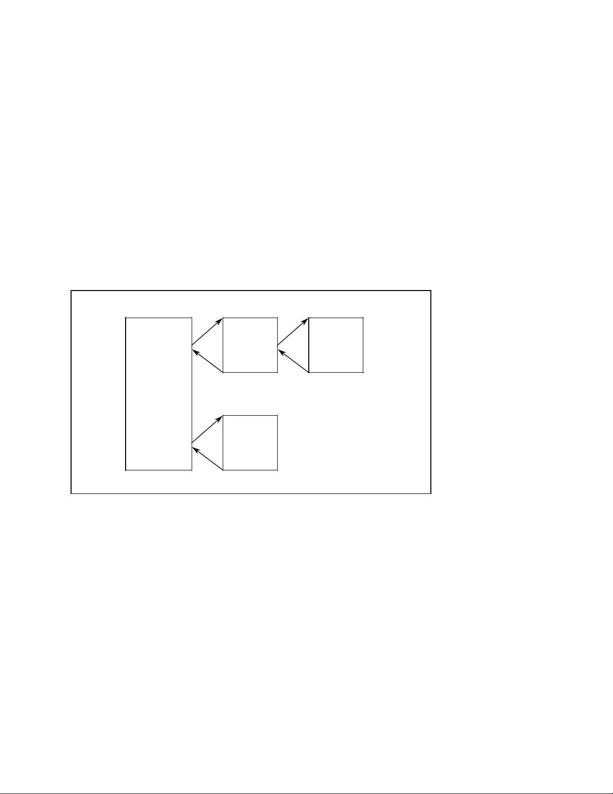
2 Organization, Program and Sequence Blocks 01.91
2.2 Calling blocks
2.2 Calling blocks
Block calls are used to release the blocks for execution. These block calls can be programmed
only in organization, sequence, program or function blocks.
(Only organization blocks may not be invoked by the user program).
A block call is comparable to a ”subroutine branch”, and may be both conditional and
unconditional.
A ”BE” statement is used to return to the block that contained the block call. No further logic
operations can be carried out on the RLO following a block call or a ”BE”. The RLO (result of
the logic operation) is passed to the ”new block”, and can be evaluated there.
Unconditional call: for example JU PB5
The program block is executed without regard to the RLO.
Conditional call: for example JC PB6
The program block is executed in dependence on the RLO.
A I 1.0 A I 2.0
JU PB5
O I 5.3
A I 1.5
JC PB 6
A I3.2
BE BE
Block calls for enabling execution of a program block
JC PB10
PB 6
O I 3.0
PB 10PB 5PB 1
BEBE
2-2© Siemens AG 1990 All Rights Reserved 6ZB5 410-0CM02
SINUMERIK 805 (PJ)
Page 25
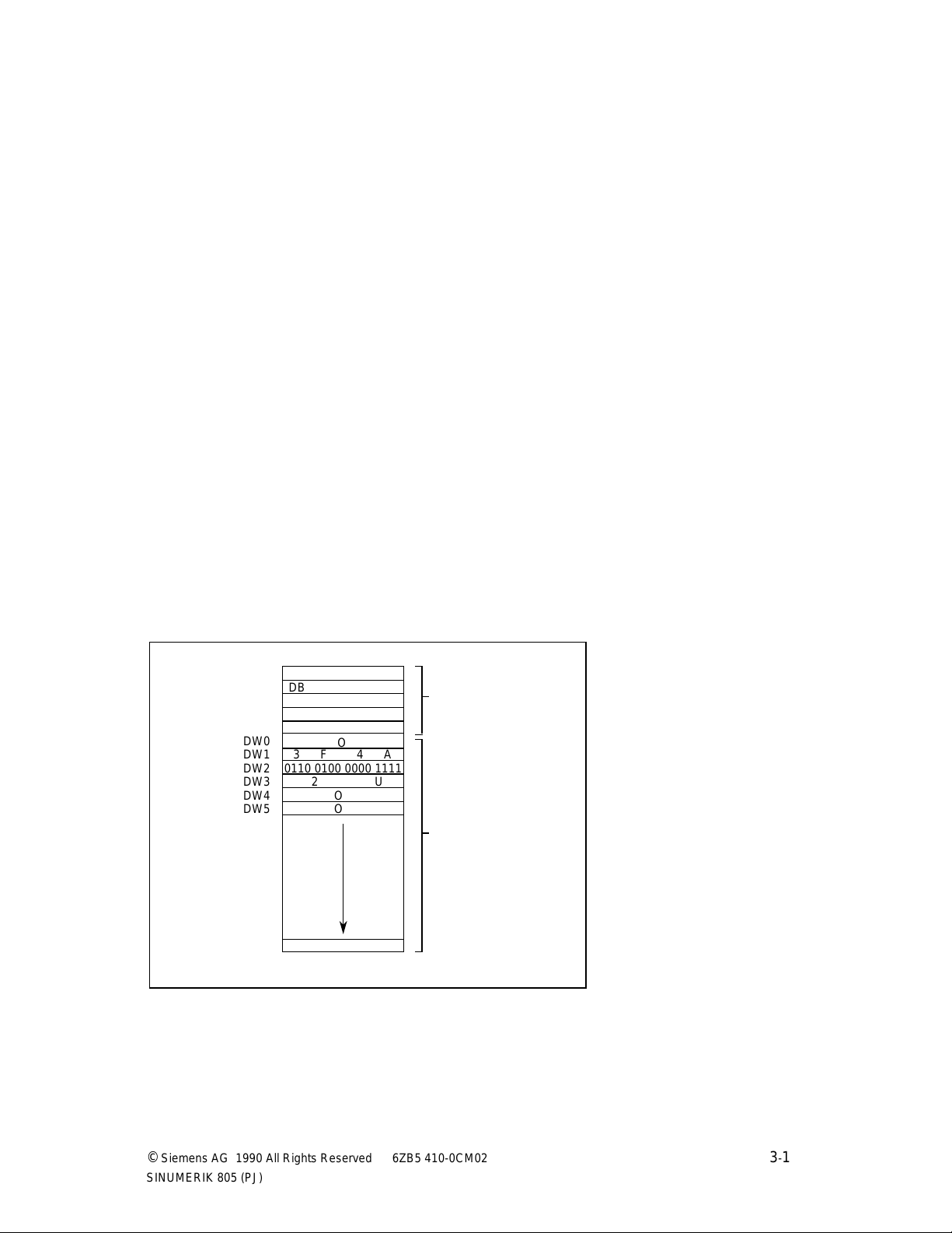
10.90 3 Data Blocks
aaaaaaaaaaaaaaaaaaaaaaaaaaaaa
a
a
a
a
a
a
a
a
a
a
a
a
aaaaa
a
a
a
a
a
a
a
aaaaa
a
3.1 Programmig data blocks
3 Data Blocks
3.1 Programming Data Blocks
The data required by the user program is stored in data blocks (DBs). No STEP 5 operations
are programmed in these blocks.
Data may be:
• Arbitrary bit patterns, e. g. for plant status indications
• Numbers (hexadecimal, binary, decimal), e. g. for times and results of arithmetic
operations
• Alphanumeric characters, e. g. for message texts
Generation of a data block on the programmer begins by specifying a data block number
between 1 and 255. Each data block (example: DB99) may comprises as many as 256 data
words (of 16 bits each). The data must be entered by word, beginning with data word 0.
One word is reserved in program memory for each data word. The programmer also generates
a block header for each data block; the header takes up five words in program memory.
The operating system generates data blocks DB1 (diagnostics DB), DB36 (read/write job
status for NC data) and DB37 (initialize the two V.24 (RS232C) interfaces) in the controller's
restart routine. The programmer (PG) prevents deletion of these blocks (message 70: DB in
EPROM).
For test purposes, however, the user can invoke the ”Force Variable” programmer function if
he wants to view or modify data words.
DW0
DW1
DW2
DW3
DW4
DW5
DW255
DB
O
3F 4A
aaaaaaaaaaaaaaaaaaaaaaaaaaa
aaaaaaaaaaaaaaaaaaaaaaaaaaa
aaaaaaaaaaaaaaaaaaaaaaaaaaa
0110 0100 0000 1111
aaaaaaaaaaaaaaaaaaaaaaaaaaa
aaaaaaaaaaaaaaaaaaaaaaaaaaa
2U
aaaaaaaaaaaaaaaaaaaaaaaaaaa
O
aaa
a
aaa
a
aaa
a
O
Block header
Data words
1 to 255
Structure of a data block
© Siemens AG 1990 All Rights Reserved 6ZB5 410-0CM02 3-1
SINUMERIK 805 (PJ)
Page 26
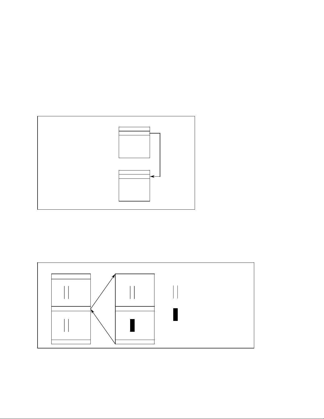
3 Data Blocks 10.90
3.2 Calling data blocks
3.2 Calling data blocks
Data blocks can be called unconditionally only. Once called, a data block remains in force until
the next is invoked.
User data blocks must not conflict with those required by the system.
A data block call can be programmed in an organization, program, function or sequence block.
The ”A DB xxx” command calls a data block, e.g. (DB10, i.e. call from DB 10).
Example 1
Transferring the contents of data word 1, data block 10 to data word 1, data block 20.
:C DB10
:L DW1
:C DB20
:T DW1
DW255
Calling a data block
DW0
DW1
DW0
DW1
DB 10
DB 20
Example 2
When a program block in which a data block has already been addressed calls another
program block that addresses another data block, the latter is valid only in the program block
that was called. The original data block is again valid following return to the calling block.
PB 7
C DB10
PB 20
DB 10 is open
C DB11SPA PB20
BEBE
Validity range of a selected data block
DB 11 is open
3-2© Siemens AG 1990 All Rights Reserved 6ZB5 410-0CM02
SINUMERIK 805 (PJ)
Page 27
05.93 3 Data blocks
aaaaaaaaaaaaaaaaaaaaaaaaaaaaaaaaaaaaaaaaaaaaaaaaaaaaaaaaaaaaaaaaaaaaaaaaaaa
aaaaaaaaaaaaaaaaaaaaaaaaaaaaaaaaaaaaaaaaaaaaaaaaaaaaaaaaaaaaaaaaaaaaaaaaaaa
aaaaaaaaaaaaaaaaaaaaaaaaaaaaaaaaaaaaaaaaaaaaaaaaaaaaaaaaaaaaaaaaaaaaaaaaaaa
aaaaaaaaaaaaaaaaaaaaaaaaaaaaaaaaaaaaaaaaaaaaaaaaaaaaaaaaaaaaaaaaaaaaaaaaaaa
aaaaaaaaaaaaaaaaaaaaaaaaaaaaaaaaaaaaaaaaaaaaaaaaaaaaaaaaaaaaaaaaaaaaaaaaaaa
aaaaaaaaaaaaaaaaaaaaaaaaaaaaaaaaaaaaaaaaaaaaaaaaaaaaaaaaaaaaaaaaaaaaaaaaaaa
aaaaaaaaaaaaaaaaaaaaaaaaaaaaaaaaaaaaaaaaaaaaaaaaaaaaaaaaaaaaaaaaaaaaaaaaaaa
aaaaaaaaaaaaaaaaaaaaaaaaaaaaaaaaaaaaaaaaaaaaaaaaaaaaaaaaaaaaaaaaaaaaaaaaaaa
aaaaaaaaaaaaaaaaaaaaaaaaaaaaaaaaaaaaaaaaaaaaaaaaaaaaaaaaaaaaaaaaaaaaaaaaaaa
aaaaaaaaaaaaaaaaaaaaaaaaaaaaaaaaaaaaaaaaaaaaaaaaaaaaaaaaaaaaaaaaaaaaaaaaaaa
aaaaaaaaaaaaaaaaaaaaaaaaaaaaaaaaaaaaaaaaaaaaaaaaaaaaaaaaaaaaaaaaaaaaaaaaaaa
aaaaaaaaaaaaaaaaaaaaaaaaaaaaaaaaaaaaaaaaaaaaaaaaaaaaaaaaaaaaaaaaaaaaaaaaaaa
aaaaaaaaaaaaaaaaaaaaaaaaaaaaaaaaaaaaaaaaaaaaaaaaaaaaaaaaaaaaaaaaaaaaaaaaaaa
aaaaaaaaaaaaaaaaaaaaaaaaaaaaaaaaaaaaaaaaaaaaaaaaaaaaaaaaaaaaaaaaaaaaaaaaaaa
aaaaaaaaaaaaaaaaaaaaaaaaaaaaaaaaaaaaaaaaaaaaaaaaaaaaaaaaaaaaaaaaaaaaaaaaaaa
aaaaaaaaaaaaaaaaaaaaaaaaaaaaaaaaaaaaaaaaaaaaaaaaaaaaaaaaaaaaaaaaaaaaaaaaaaa
aaaaaaaaaaaaaaaaaaaaaaaaaaaaaaaaaaaaaaaaaaaaaaaaaaaaaaaaaaaaaaaaaaaaaaaaaaa
aaaaaaaaaaaaaaaaaaaaaaaaaaaaaaaaaaaaaaaaaaaaaaaaaaaaaaaaaaaaaaaaaaaaaaaaaaa
3.3 Data blocks created by the system program
3.3 Data blocks created by the system program
DB 1: Diagnostics DB
(for details see Section 8.1)
DB 28: Analog setpoint value output
DB 36: Status data transfer for FB 61/62
DB 37: Serial interface
For more detailed information on data blocks DB28, DB36
and DB37 please refer to
Interface Description Part 1, Signals.
© Siemens AG 1990 All Rights Reserved 6ZB5 410-0CM02 3–3
SINUMERIK 805 (PJ)
Page 28

10.90 4 Function Blocks
4.1 General remarks
4 Function Blocks
4.1 General remarks
Function blocks are used to implement frequently recurring or extremely complex functions.
Functions blocks (FBs) are as much a part of the user program as, for example, program
blocks. There are three basic differences between function blocks and organization, program
or sequence blocks:
• Function block can be initialized, i. e. a function block's formal parameters can be
replaced by the actual operands with which the function block is called.
• In contrast to organization, program and sequence blocks, an extended operation set
comprising the STEP 5 supplementary operations (see also Section 9.4) can be used to
program function blocks, and only function blocks.
• The program in a function block can be generated and logged in statement list form
only.
The function blocks in a user program represent complex, self-contained functions. A function
block programmed in the STEP 5 language can be programmed by the user himself, or may
be purchased from Siemens as a software product. In addition, a number of pretested,
technology-specific function blocks can be assembled to form function macros and linked into
the basic program. The user can call these macros as he would a function block, but he
cannot modify them. These blocks are written in assembly language and are also referred to
as ”resident” or integral function blocks” (cf. Section 6.1).
Siemens AG 1990 All Rights Reserved 6ZB5 410-0CM02 4-1
©
SINUMERIK 805 (PJ)
Page 29
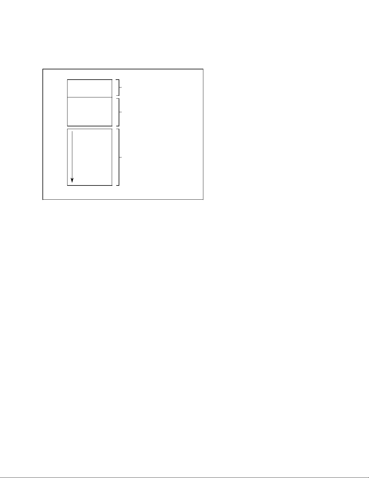
4 Function Blocks 10.90
4.2 Structure of function blocks
4.2 Structure of function blocks
A function block comprises a block header, name and parameter declaration, and the block
body.
Block header
Name and parameter
declarations
Block body with STEP 5
program or assembly
language statements
Structure of a function block
4.2.1 Block header
The block header contains all information which the programmer needs in order to display the
function block in graphic form and check the operands when the function block is initialized.
The user must enter the header (using the programmer) before programming the function
block.
4.2.2 Block body
The block body contains the actual program, i. e. describes the function to be executed in the
STEP 5 language. Only the block body is processed when the function block is called.
The programmer echoes the block name and parameter declaration when integral assemblylanguage function blocks are called.
When the ”first executable statement” in the block body is the ”ASM” STEP 5 command
(switch to assembly code), the processor executes the subsequent assembly language
statements immediately.
-2© Siemens AG 1990 All Rights Reserved 6ZB5 410-0CM02
4
SINUMERIK 805 (PJ)
Page 30

10.90 4 Function Blocks
4.3 Calling and initializing function blocks
4.3 Calling and initializing function blocks
Function blocks (FBs) are present only once in memory. They can be called once or more
than once by a block, and different parameters can be used for each call.
Function blocks are programmed or called by specifying a block number (FB 0 to 255).
A function block call can be programmed in an organization, sequence or program block or in
another function block. A call comprises the call statement and the parameter list.
4.3.1 Call statement
Unconditional call: e.g. JU FB 30
The function block is executed without regard to the RLO.
Conditional call: e.g. JC FB 35
The function block is executed only when the RLO is in signal state ”1”.
4.3.2 Parameter list
The parameter list immediately follows the call statement, and defines all input variables,
output variables and data. The parameter list may contain no more than 40 variables.
The variables from the parameter list replace the formal parameters when the function block is
executed. The programmer (PG) monitors the order in which the variables are entered in the
parameter list.
The programmer automatically generates, but does not display, the jump statement that follows
the FB call.
The FB call reserves two words in program memory, and each parameter one additional word.
The identifiers for the function block's inputs and outputs and the name of the function block
are displayed on the programmer when the user programs the function block.
This information is in the function block itself. It is therefore necessary that all required function
blocks either be resident as function macro in the PLC's basic software, be transferred to the
program diskette, or be entered directly into the programmable controller's program memory
before function block programming can begin (for details, refer to the Operating Instructions).
Siemens AG 1990 All Rights Reserved 6ZB5 410-0CM02 4-3
©
SINUMERIK 805 (PJ)
Page 31

4 Function Blocks 10.90
4.4 Programming function blocks
PB 3
Is generated by the pro-
Is generated by the pro-
Calling a function block
grammer
Parameter list
grammer
Parameter list
Call
Call
JU FB 5
JU + 5
I 2.4
T5
F 3.1
Q 6.0
AI 3.2
AI 5.1
JC FB 5
JU + 5
I 5.2
T7
F 3.6
F 5.0
BE
FB 5
A =PAR 1
O =PAR 2
O =PAR 3
= =PAR 4
BE
Block header
formal
parameters
4.4 Programming function blocks
In keeping with its structure, a function block is generated in two parts:
the block header and the block body.
The block header must be entered before the block body (STEP 5 program). The block header
contains:
• The library number
• The name of the function block
• The formal operands (the names of the block parameters)
• The block parameters
4.4.1 Library number
The library number may be a number between 0 and 65535. The function block is assigned
this number without regard to its symbolic or absolute parameters.
A library number should be assigned only once to permit unique identification of a function
block. Standard function blocks have a product number.
4.4.2 Name of the function block
The name that identifies the function block may comprise no more than eight characters, the
first of which must be a letter.
-4© Siemens AG 1990 All Rights Reserved 6ZB5 410-0CM02
4
SINUMERIK 805 (PJ)
Page 32

10.90 4 Function Blocks
4.4.3 Formal operand (block parameter names)
4.4.3 Formal operand (block parameter name)
A formal operand may comprise no more than four characters, the first of which must be a
letter. A maximum of 40 parameters can be programmed per function block.
STL
:JU FB 201
NAME :E-ANTR
ZU-E : DW1
RME : I 3.5
ESB : F 2.5
UEZ : T 2
ZEIT : KT010.1
ZU-A : DW2
BEA : Q 2.3
LSL : Q 6.0
Formal operands (names of the block parameters)
(max. 4 characters, the first of which must be a letter)
LAD/CSF
DW 1
I 3.5
F 2.5
T2
KT010.1
Example: Calling a function block
FB 201
Formal operands (names of the block parameters)
Name of the function block
(max. 8 characters, the first of
which must be a letter)
ZU-E ZU-A
RME BEA
ESB LSL
UEZ
ZEIT
DW 2
Q 2.3
Q 6.0
© Siemens AG 1990 All Rights Reserved 6ZB5 410-0CM02 4-5
SINUMERIK 805 (PJ)
Page 33

4 Function Blocks 10.90
4.4.4 Block parameter types
4.4.4 Block parameter types
A block parameter may be of type ”I”, ”Q”, ”D”, ”B”, ”T”, or ”C”.
I = Input parameter
Q = Output parameter
D = Data
B = Block
T = Timer
C = Counter
In graphic representation, parameters of type ”I”, ”D”, ”B”, ”T” and ”C” are shown at the left
of the function symbol and those of type ”Q” at the right. Operations to which parameters are
to be assigned (substitution operations) are programmed in the function block with formal
operands. The formal operands may be addressed at various locations within the function
block.
STL
:JU FB 202
NAME :EXAMPLE
ANNA : I 13.5
BERT : F 17.7
HANS : Q 23.0
LAD/CSF
FB 202
I 13.5
F 17.7
Program in the function block
NAME :EXAMPLE
ID :ANNA I/Q/D/B/T/C: I BI/BY/W/D: BI
ID :BERT I/Q/D/B/T/C: I BI/BY/W/D: BI
ID :HANS I/Q/D/B/T/C: Q BI/BY/W/D: BI
:A = ANNA
:A = BERT
:= = HANS
Program executed
:A I 13.5
:A F 17.7
:= Q 23.0
ANNA HANS
BERT
Formal operand
Q 23.0
Parameter type
Parameter type
Actual operand
Example: Calling a function block
4-6© Siemens AG 1990 All Rights Reserved 6ZB5 410-0CM02
SINUMERIK 805 (PJ)
Page 34

10.90 4 Function blocks
4.4.5 Block parameters and permitted actual parameters
4.4.5 Block parameters and permitted actual parameters
Type of Type of data Permitted actual parameters
parameter
I, Q BI for operands with bit addresses I n.m Input
BY for operands with byte addresses IB n Input bytes
W for operands with word addresses IW n Input words
D for operands with ID n Input double words
double word addresses QD n Output double words
D KM for a bit pattern (16 bits) Constants
KY for two integer numbers expressed in
bytes each in the range 0 to 255
KH for a hexadecimal pattern (max.
4 positions)
KC for a symbol (max. 2 alphanumeric
characters
KT for a time (time in BCD) with time base
1.0 to 999.3
KZ for a counter value (BCD) 0 to 999
KF for a fixed-point number in the range
- 32768 to + 32767
KG for a floating-point number
Q n.m Output
F n.m Flag
QB n Output bytes
FY n Flag bytes
DL n Data bytes left
DR n Data bytes right
PB n Peripheral bytes
QW n Output words
FW n Flag words
DW n Data words
PW n Peripheral words
FD n Flag double words
DD n Data double words
B Type specification not permitted DB n Data block, the statement CDBn is
FB n Function blocks (without para-
PB n Program blocks are called un-
SB n Sequence blocks
T Type specification not permitted T Timer, the time is specified as data
C Type specification not permitted C Counter; the count is specified as
executed
meter)
conditionally (SPA ..n)
are called uncondictionally (SPA ..n)
or as a constant in the function block
data or as a constant in the function
block
© Siemens AG 1990 All Rights Reserved 6ZB5 410-0CM02 4-7
SINUMERIK 805 (PJ)
Page 35

01.91 5 Program Organization
5.1 General remarks
5 Program Organization
5.1 General remarks
The organization blocks form the interface between the operating system and the user
program.
The organization blocks (OBs) are as much a part of the user program as are program blocks,
sequence blocks and function blocks, but only the operating system can invoke them. A user
can only program organization blocks; he cannot invoke them.
FBPBOB
BE BE
OB FBPB
OB Organization block
PB Program block
FB Function block
BE
BE
User programOperating system
BEBE
PLC program
© Siemens AG 1990 All Rights Reserved 6ZB5 410-0CM02 5-1
SINUMERIK 805 (PJ)
Page 36

5 Program Organization 01.91
5.2 Cyclic scanning
Appropriate programming of the organization blocks enables the following:
• One-shot execution following PLC restart (OB 20)
• Cyclic execution (OB 1)
(see page 5-3, ”Programming the cyclic program”)
• Execution of the interrupt service routine (OB 2)
(see page 5-7, ”Programming the interrupt service routine”)
OB 2 must be available when interrupt processing is enabled (PLC MD 2002, bit 0=0),
otherwise the PLC will stop. OB 20 and OB 1 can be installed in the PLC as required. If one of
these two OBs is missing this fact is ignored by the operating system.
The organization blocks are programmed in the same manner as program or sequence blocks,
and can be programmed and documented in all three methods of representation (statement list
STL, control system flowchart CSF, ladder diagram LAD).
5.2 Cyclic scanning
5.2.1 Interrupt capability
The cyclic user program can be interrupted after each MC5 instruction. The last instruction is
executed in its entirety and pending interrupts (caused by a process interrupt or higher-priority
sections of the NC program) are enabled when the instruction been executed.
If the interrupt was caused by detection of an edge change in the interrupt input byte, all MC5
registers, as well as flag bytes 224 to 255, are saved; these registers and flag bytes are
recovered following termination of the interrupt service routine. The data block open prior to
the interrupt is thus once again valid.
-2© Siemens AG 1990 All Rights Reserved 6ZB5 410-0CM02
5
SINUMERIK 805 (PJ)
Page 37

05.93 5 Program Organization
5.2.2 Response time and cycle time
5.2.2 Response time and cycle time
• Response time:
The response time to a process signal or a signal from the NC is defined as follows:
The PLC operating system forwards the signal to the user interface (I, F area), invokes and
executes the cyclic user program (OB 1) and transfer the process output image updated
by OB 1 to the I/Os and the NC.
The response depends on:
1) Type and length of the cyclic user program in OB 1
2) Execution mode of the cyclic user program (PLC MD 2003, bit 6: fragmentation,
no fragmentation)
3) Timing grid for the cyclic user program scanning by the PLC operating system
4) Execution time of the higher-priority NC program blocks and of the interrupt service
routine (OB 2) where applicable
5) Instant: Process image updating by the PLC operating system and actual signal
status change (I/Os, internal NC-PLC interface)
• Cycle time:
The cycle time is the period between two updatings of the process input image by the PLC
operating system. Because the PLC invokes the cyclic user program in accordance with a
specific timing grid rather than restarting it immediately after it has terminated, the cycle
time can never be less than 48 ms (up to SW 4.1: 60 ms) (possible cycle times: 48 ( 60 )
ms, 96 (120) ms, 144 (180) ms , etc).
Like the response time, the cycle time is dependent on the conditions listed in 1-3 (above).
It can be ascertained by invoking the diagnostic function (PLC MD 2003, bit 7 = 1), and is
monitored to ensure that it does not exceed a maximum value (PLC MD5 default is
300 ms). If it does, the PLC will stop.
5.2.3 Programming the cyclic program
A programmable controller's program is ”normally” scanned cyclically. The processor starts at
the beginning of the STEP 5 program, scans the STEP 5 statements sequentially until it
reaches the end of the program, and then repeats the entire procedure.
Siemens AG 1990 All Rights Reserved 6ZB5 410-0CM02 5-3
©
SINUMERIK 805 (PJ)
Page 38

5 Program Organization 11.91
5.2.4 Interface between system program and cyclic processing
5.2.4 Interface between system program and cyclic processing
Organization block OB 1 is the interface between the system program and the cyclic user
program. The first STEP 5 statement in OB 1 is also the first statement in the user program,
i. e. is equivalent to the beginning of the cyclic program.
The program, sequence and function blocks comprising the cyclic program are called in
organization block 1. These blocks may themselves contain block calls, i. e. the blocks can be
nested (see Section 1, ”Program organization”).
System program PB nOB 1
1
PB call
2
etc.OB 1 call
5 4
System program User program
Cyclic program scanning
1
First statement in the STEP 5 program.
2
First PB call. The block called may contain additional calls
3
BEBE
(cf. Section 1, ”Program organization”).
3
Return from the last program or function block executed.
4
The organization block is terminated with BE.
5
Return to system program.
The user program's runtime is the sum of the runtimes of all blocks called. When a block is
called ”n” times, its runtime must be added to the total ”n” times.
-4© Siemens AG 1990 All Rights Reserved 6ZB5 410-0CM02
5
SINUMERIK 805 (PJ)
Page 39

01.91 5 Program Organization
5.2.5 Basic program organization
5.2.5 Basic program organization
Organization block OB 1 contains the basic structure of the user program. A diagram of this
block shows the essential program structures at a glance and emphasizes programinterdependent plant sections.
OB 1
JU PB ”A”
JU PB ”B”
JU PB ”C”
PB
”A”
Operating
mode program
BE
PB ”B”
Sequence
control
PB ”C”
Individual
control level
FB
Halt,
emergency
shutdown
BE
FB
Bring to initial
state
BE
FB
Sequencer
control
BEBE
FB
Group control
BE
FB
Unit control
BE
SB
Sequence step
BE
SB
Sequence step
BE
DB
Interface flags
for the
individual
control modules
FB
Unit control
BE
Breakdown of the user program based on the progam structure
BE
BE
© Siemens AG 1990 All Rights Reserved 6ZB5 410-0CM02 5-5
SINUMERIK 805 (PJ)
Page 40

5 Program Organization 01.91
5.2.5 Basic program organization
OB 1
JU PB ”X”
JU PB ”Y”
PB ”X”
Plant
section ”X”
BE
PB
”Y”
Plant
section ”Y”
BE
FB
Individual
control
BE
FB
Closed-loop
control
BE
FB
Message
control
BE
FB
Sequence
control
BE
FB
Message
control
BE
PB ”Z”
Plant
section ”Z”
JU PB ”Z”
BE
Breakdown of the user program based on the plant structure
FB
Closed-loop
control
BE
FB
Arithemetic
BE
FB
Logging
BEBE
5-6© Siemens AG 1990 All Rights Reserved 6ZB5 410-0CM02
SINUMERIK 805 (PJ)
Page 41

05.93 5 Program Organization
5.3 Interrupt processing
5.3 Interrupt processing
5.3.1 Programming the interrupt service routine
The PLC has interrupt-processing capabilities.
In this mode, the cyclic program is interrupted and an interrupt service routine (OB 2)
executed. Once the interrupt service routine has terminated, the processor returns to the point
of interruption and resumes execution of the cyclic program.
The interrupt service routine is initiated when the signal state of a bit of the interrupt input byte
(specified in the PLC MD 0) changes.
Interrupt service routines allow the user to react immediately to process signals. An edge
change in these signals is thus registered before the process image is updated, thereby
minimizing the response time to time-critical functions in the process.
Because the PLC operating system does not transfer the process image to the I/Os when OB
2 terminates, the user must himself influence the process peripherals with STEP 5 commands
T PB/T PW.
5.3.2 Interface between system program and the interrupt
OB 2 is the interface between the operating system and the interrupt service routines.
OB 2 is always invoked when the signal state of a bit in the interrupt input byte changes.
The user may select the input bit via machine data (PLC MD0: maximum value 31).
PLC MD 2002, bit 0 must also be set to 0 to enable interrupts.
When one of the selected bits changes from ”0” to ”1” (positive edge) or from ”1” to ”0”
(negative edge), the interrupt service routine is invoked, i. e. the operating system calls OB 2,
which contains the user's interrupt service routine.
The operating system checks the interrupt bytes every 4 ms (up to SW 4.1: 5 ms) to
determine whether there was a change to a bit in the interrupt input byte during the service
routine and invokes an interrupt service routine when required.
The type of signal change (positive or negative edge) is entered as input parameter in flag
bytes FB 12 and FB 16.
The PLC operating system resets flag bytes FB 12 and FB 16 when OB 2 terminates
Siemens AG 1990 All Rights Reserved 6ZB5 410-0CM02 5-7
©
SINUMERIK 805 (PJ)
Page 42

5 Program Organization 11.91
5.3.3 Response time
5.3.3 Response time
The following factors influence the interrupt service routine's response time to an edge change
in the interrupt input byte:
• Whether the interrupt input byte is a global or local I/O byte
• The instant at which the edge change takes place in the interrupt input byte and that at
which the PLC operating system scans that byte
Approximate response times:
• Global interrupt input byte:
The response time is between 2 ms and 7.5 ms.
• Local interrupt input byte:
The response time is between 3.5 ms and 9 ms.
-8© Siemens AG 1990 All Rights Reserved 6ZB5 410-0CM02
5
SINUMERIK 805 (PJ)
Page 43

01.91 6 Integral Function Blocks
6.1 General remarks
6 Integral Function Blocks
6.1 General remarks
Function macros are function blocks that are written in assembly language and integrated in
the operating system.
The user can invoke and initialize these blocks in the same way as STEP 5 blocks. They are
used for time-critical functions, and execute much faster than comparable STEP 5 blocks. The
user should therefore give the integral blocks preference over the conventional STEP 5 blocks.
only
When this block is output
Note the following when linking the blocks into the user program:
1. These blocks can be called by other blocks when the user program is generated ON-LINE
(entered direct in the PLC from the programmer). The corresponding parameter table is
displayed on the PG screen, and the user can make all required entries.
2. When programming direct on diskette, the function macros to be called must be diskresident, i. e. the user must transfer the macros from the PLC to a workdisk. Only the
block headers with parameter block are transferred.
the block header is displayed.
3. When these FBs are called in the user program, the user need only initialize the parameter
table.
Loading the PLC blocks:
STEP 5 function blocks that have the same numbers as function macros cannot be transferred
to the PLC (PG message: ”Block already in EPROM”, i.e. these functon blocks are already
contained in the system EPROM.
Siemens AG 1990 All Rights Reserved 6ZB5 410-0CM02 6-1
©
SINUMERIK 805 (PJ)
Page 44

6 Integral Function Blocks 01.91
6.2 FB identifiers
6.2 FB identifiers
FB call Parameter type
I Input
Q Output
B Block
T Timer
C Counter
D Data
§I,..
I,BI - Q
I,BI - /
D,..
B
T
C
$F...
$DW...
*F...
*DW...
FB Name
Q,...
Q - Q,BI
I - Q,BI
$F...
$DW...
*F...
*DW...
- % 1
- %v1
Data type
BI Operand with bit
address
BY Operand with
byte address
W Operand with
word address
Not applicable
Not applicable
Not applicable
KM Bit pattern, 16 digits
KY Two absolute values (1 per byte) from 0 to 255
KH Hexadecimal number, max. 4 digits
KC Two alphanumeric characters
KT Time (BCD coded) from 1.0 to 999.3
KZ Count (BCD coded) from 0 to 999
KF Fixed-point number (-32768 to +32767)
Permissible actual operands
I n.m Input
Q n.m Output
F n.m Flag
IB n Input byte
QB n Output byte
FY n Flag byte
DL n Data byte left
DR n Data byte right
PB n Peripheral byte
IW n Input word
QW n Output word
FW n Flag word
DW n Data word
PW n Peripheral word
DB n Data block
FB n Function block
PB n Program block
SB n Sequence block
T n No. of the timer
Z n No. of the counter
I,BI
I,BI -Q
I,BI - /
§I,..
$...
*...
Q- Q,BI
I- Q,BI
Q,BI
$...
*...
% 1
%v1
Static input signal
Input signal acknowledged by FB
Input signal whose rising edge is evaluated
DW not allowed as parameter
Input signal which must be supplied prior to calling the FB
Fixed input signal which need not be generated
Static output signal
Output signal which must be acknowledged by the user
Output signal for one cycle (pulse)
Output signal at defined flag word or data word which can
be evaluated immediately following the FB
Defined output signal, e. g. NC signal
Error code ACCU 2 on system stop (STS); ACCU 1
error code
Aux. spec.: No. of the interface byte in ACCU2's HIGH
byte
6-2© Siemens AG 1990 All Rights Reserved 6ZB5 410-0CM02
SINUMERIK 805 (PJ)
Page 45

01.91 6 Integral Function Blocks
6.3 Function macros
6.3 Function macros
FB No. FB ID FB NAME Section
11 EINR-DB Generate data blocks 6.3.1
60 FB BLOCK-TR Block transfer 6.3.2
61 FB NCD-LESE Read NC data 6.3.3
62 FB NCD-SCHR Write NC data 6.3.3
65 M STACK Transfer flags flag stack 6.3.4
66 STACK M Flag stack transfer flags 6.3.4
104 SEND
105 RECEIVE
106 CONTROL
These function blocks are only available when the
”SINEC L2” functionality is activated.
See the Function Manual ”SINEC L2 Interface
Module”, order number: 6ZB5 410-0DQ02-0AA0 for
details
© Siemens AG 1990 All Rights Reserved 6ZB5 410-0CM02 6-3
SINUMERIK 805 (PJ)
Page 46

6 Integral Function Blocks 01.91
6.3.1 FB 11 EINR-DB
6.3.1 FB 11 EINR-DB Generate data blocks
1. Description
The EINR-DB function block is used to generate data blocks for variable data in the PLC's
RAM.
EINR-DB generates the specified data block, e.g. in the cold restart routine (OB 20), but only
when the DB is not yet in the address table and a valid data word number is specified.
The interface flags (FW 246 and FW 248) are evaluated when parameter AN = 0.
The PLC branches into the stop loop if one of the following parameter errors is signaled:
• 255< DW no. < 0
• Data block number > 255
• Data block number = 0
• Not enough RAM available in PLC
• Data block already in PLC and lengths are not identical
A detailed error identifier is entered in ACCU 2 (ACCU 1 contains the block number). The data
block is initialized to zero.
Note: The data blocks for the basic software (interface data blocks) are generated
automatically in the cold restart routine.
2. Block data
Bit no. :
FBs to be loaded : None
DBs to be loaded : None
Type of FB call : unconditional or conditional (JU FB11 or JC DB11)
DBs to be entered : None
Error messages : %2 DB no. > 255
%3 Spec. DWNR < 0
%4 Length of DBto be generated not identical with length of DB in
PLC
%5 Not enough RAM available in PLC
%6 Spec. DWNR > 255
%7 DB0 cannot be generated
-4© Siemens AG 1990 All Rights Reserved 6ZB5 410-0CM02
6
SINUMERIK 805 (PJ)
Page 47

10.90 6 Integral Function Blocks
6.3.1 FB 11 EINR-DB
3. Block call
FB EINR-DB
D, KY –
D, KF –
DBAN
DWNR
–%2
–
%3
$ FW 246 –
DBAN
–
%4
–%5
$ FW 248 –
DWNR
–%6
–
%7
4. Signals
DBAN Number of data blocks to be generated and their numbers.
Special case:
When parameter AN = 0, the function block can be initialized over flag words
FW 246 and FW 248.
High-Byte : DB number
Low-Byte: Number of data blocks (minimum of 1)
DWNR No. of the last DW
5. Example
If DB 150 is not available, it must be generated up to DW 10 on a new start (FB 11
programmed in DB 20).
a) direct parameter assignment b) indirect parameter assignment
OB20 OB 20
Network 1 0000 Network 1 0000
0000 : 0000 :
0001 : 0001 :
0002 : JU FB 11 0002 : L KY
150,1
0003 NAME : EINR-DB 0004 : T FW 246
0004 DBAN : KY 150,1 0005 : L KF +10
0005 DWNR : KF +10 0007 : T FW 248
0006 : 0008 : JU FB 11
0007 : 0009 NAME : EINR-DB
000A DBAN : KY 150,0
000B DWNR : KF +10
000C :
000D :
Siemens AG 1990 All Rights Reserved 6ZB5 410-0CM02 6-5
©
SINUMERIK 805 (PJ)
Page 48

6 Integral Function Blocks 10.90
6.3.2 FB 60 BLOCK-TR
6.3.2 FB 60 BLOCK-TR block transfer
1. Description
Function block BLOCK-TR transfers the specified number of data words from a source DB
located in RAM to a destination DB in RAM.
The user may specify both the start of the source DB block to be transferred and the start
data word in the destination DB.
Prior to initiating the transfer, the PLC checks to make sure that:
• The source DB in the PLC has the required length
• The destination DB in the PLC has the required length
• The destination DB is located in RAM
• The number of data words to be transferred is > 0 and < 129
The PLC enters the Stop loop when an error is detected. A detailed error identifier is entered
in ACCU 2 (ACCU 1 = block number). Flag words FW 250-254 are scanned when the
QZ” parameter is zero.
”DB
(Initialization: 0.1 1.0 or 0.0).
2. Block data
Bit no. :
FBs to be loaded : None
DBs to be loaded : None
Type of FB call : Absolute or conditional (JU FB 60 or JC FB 60)
DBs to be entered : None
Error messages : %1 No. of DWs to be transferred > 128
%2 No. of DWs to be transferred = 0
%3 No source DB
%4 No destination DB
%5 Destination DB too short
%7 Source DB too short
3. Block call
FB BLOCK-TR
D, KY -
D, KF -
D, KY -
$FW 254 $FW 250 $FW 252 -
6-6© Siemens AG 1990 All Rights Reserved 6ZB5 410-0CM02
DBQZ
DWQ
DZ/A
DBQZ
DWQ
DZ/A
- %1, %2,
- %3, %4
- %5, %6
- %7
SINUMERIK 805 (PJ)
Page 49

10.90 6 Integral Function Blocks
aaaaaaaaaaaaaaaaaaaaaaaaaaaaaaaaa
a
a
aaaaaaaaaaaaaaaaaaaaaaaaaaaaaaaaa
a
a
a
a
a
aaaaaaaaaaaaaaaaaaaaaaaaaaaaaaaaa
a
a
a
a
a
aaaaaaaaaaaaaaaaaaaaaaaaaaaaaaaaa
a
a
a
a
a
6.3.2 FB 60 BLOCK-TR
4. Signals
DBQZ Source DB and destination DB numbers
High byte : Source DB
Low byte : Destination DB
DWQ Start of the data block to be copied in the source DB
DZ/A Start of the data block in the destination DB and number of data words to be
transferred
High byte : Start of the data block
Low byte : Number of data words to be transferred
5. Example
FB BLOCK-TR
10,11 -- DBQZ
8 -- DWQ
12,05 -- DZ/A
6. Data transfer diagram
Source DB
(high byte of DBQZ) (low byte of DBQZ)
DW 0
DW Q
aaaaaaaaaaaaaaaaaaaaaaaaaaaaaaa
aaaaaaaaaaaaaaaaaaaaaaaaaaaaaaa
aaaaaaaaaaaaaaaaaaaaaaaaaaaaaaa
aaaaaaaaaaaaaaaaaaaaaaaaaaaaaaa
5 data words, beginning with DW8, are copied
from DB 10 to DB 11; the first destination data
word is DW 12.
1)
Destination
High byte
of DZ/A
a
a
a
a
aaaaaaaaaaaaaaaaaaaaaaaaaaaaaaa
aaaaaaaaaaaaaaaaaaaaaaaaaaaaaaa
aaaaaaaaaaaaaaaaaaaaaaaaaaaaaaa
a
a
Low byte
of DZ/A
1) The ”source” data block may be located in either RAM or EPROM
© Siemens AG 1990 All Rights Reserved 6ZB5 410-0CM02 6-7
SINUMERIK 805 (PJ)
Page 50

6 Integral Function Blocks 10.90
6.3.3 FB 61 NCD-LESE, FB 62 NCD-SCHR
6.3.3 FB 61 NCD-LESE Read NC data FB 62 NCD-SCHR Write NC data
1. Description
Function blocks FB 61 and FB 62 are used to read NC data from/write NC data to the PLC.
Prerequisite is that the job-controlled data interchange between NC and PLC has been enabled
by NC MD 5015 bit 1 (external data input).
Parameters must be initialized to inform the function blocks of the data source in the NC or
PLC and of the data destination in the PLC or NC. The function blocks must be assigned a
byte in the interface data area (DB 36) over the NBSY parameter; this byte informs the
function blocks of the current state of the data transfer.
The NC/PLC data transfer function is described in detail in Section 7. NC interrupt 3016 is
issued when the NC's data type is unknown.
2. Block data
FBs to be loaded : None
DBs to be loaded : None
Type of FB call : Unconditional or conditional
DBs to be entered : None
Error messages : ACCU 1 (FB no.) = 61 or 62
ACCU 2, high byte, = no. of the interface byte, i. e. the number of
the job that produced the error (exception: error 8).
ACCU 2 low byte = detailed error code:
0 : ANZ >1 not allowed
1 : Invalid interface byte
2 : Addressed data word missing / DB missing or DB no. / FW no.
invalid
3 : Invalid data type
4 : *ANZ =< 0 or >80
5 : Illegal read / illegal write
6 : Invalid number format
7 : Value 3 (WER3) not 0 (ZOA) or 1 (ZOFA)
8 : Read/write NC data not enabled (option)
* Refer to the exceptions for the ANZ parameter
-8© Siemens AG 1990 All Rights Reserved 6ZB5 410-0CM02
6
SINUMERIK 805 (PJ)
Page 51

01.91 6 Integral Function Blocks
6.3.3 FB 61 NCD-LESE, FB 62 NCD-SCHR
3. Block call
FB 61: NCD-LESE
I, BI -- LESE
I, BY -- NSBY
D, KF -- ANZ
D, KS -- DTY1
D, KS -- DTY2
D, KS -- DTY3
D, KF -- WER1
D, KF -- WER2
D, KF -- WER3
D, KS -- ZFPN
D, KY -- ZIEL
$FB 242 -- NSBY -- % 0
$FB 243 -- ANZ -- % 1
$FW 244 -- WER1 -- % 2
$FW 248 -- WER2 -- % 3
$FW 250 -- WER3 -- % 4
$FW 252 -- ZFPN -- % 5
$FW 254 -- ZIEL -- % 6
-- % 7
FB 62: NCD-SCHR
I, BI -- SCHR
I, BY -- NSBY
D, KF -- ANZ
D, KS -- DTY1
D, KS -- DTY2
D, KS -- DTY3
D, KF -- WER1
D, KF -- WER2
D, KF -- WER3
D, KS -- ZFPN
D, KY -- QUEL
$FB 242 -- NSBY -- % 0
$FB 243 -- ANZ -- % 1
$FW 244 -- WER1 -- % 2
$FW 248 -- WER2 -- % 3
$FW 250 -- WER3 -- % 4
$FW 252 -- ZFPN -- % 5
$FW 254 -- QUEL -- % 6
-- % 7
-- % 8
4. Signals
LESE The parameters are transferred to the FIFO buffer (job buffer) when the LESE (read)
SCHR or SCHR (write) signal = 1.
In case of an unconditional block call, the user has to reset the LESE or SCHR signal
at the end of the data transfer.
On an unconditional block call, the signal must be set to ”1” (F 0.1) (see also timing
diagrams). Data transfer can be activated only when the initialized interface byte's
(NSBY's) DATA TRANSFER ENABLED signal is 0.
NSBY The function block must be assigned a byte in the interface data area (DB 36) from
which it can ascertain the current state of the data transfer.
Exception: Variable initialization; refer to the overview on the next page.
Note:
When byte DL32 (= number 65) is used as interface byte, the specified job request
is serviced on an ”interrupt-driven” basis, i. e. it is ”sandwiched” between the job
requests that are already in the request buffer. With job number 65 and ANZ > 1,
the interrupt job is executed fully.
© Siemens AG 1990 All Rights Reserved 6ZB5 410-0CM02 6-9
SINUMERIK 805 (PJ)
Page 52

6 Integral Function Blocks 01.91
6.3.3 FB 61 NCD-LESE, FB 62 NCD-SCHR
ANZ Number of data words to be transferred. If more than one word is transferred
(ANZ > 1), both source and destination addresses are incremented. If this results,
for example, in addressing of a data word that is no longer available, the PLC goes to
STOP with % 2 (ACCU 2).
Note that a different number of data words is required for each value transferred,
depending on the ZFPN parameter.
Exceptions:
When ANZ is 0 or 128, the NSBY, ANZ, WER1-WER3, ZFPN and ZIEL/QUEL
parameters are initialized over flag words. The information presented in 5. below
(Variable initialization) discusses the difference between ANZ = 0 and ANZ = 128.
DTY1 2 to 6 ASCII characters; CL800 mnemonics (cf. table, para. 7).
DTY2 The values must be input, beginning with DTY1.
DTY3 Missing characters must be filled out with blanks.
WER1 Values entered according to data type (see following table, section 7)
WER2 Example: R parameter R897, data type RPNC, WER1=1, WER2=897
WER3 See following table, section 7
ZFPN PLC/NC number format
Overview of PLC/NC number format is in section 6
ZIEL Data destination in the PLC (FB 61) high byte: DB number (2 - 255)
exception: 0 = flag
QUEL Data source in the PLC (FB 62) low byte: word number (for DBs)
byte number (for flags)
(136 - 255 permissible)
Note:
1. The number of bytes required must accord with the ZFPN parameter.
2. If, for example, a 16-bit word is to be passed to the NC, the value, when transferred, must
be written from data words into the initialized word k + 1
when number formats FO-FF are
needed.
The parameterized word k has to be set to 0 (see para. 6).
5. Indirect initialization
When the indirect initialization option is used, the values must be written into the flag words in
the same format as for direct initialization of the FB.
Example:
The following must be programmed to initialize the ZFPN parameter with F1:
.
.
L KSF1
T FW252
.
.
.
-10 © Siemens AG 1990 All Rights Reserved 6ZB5 410-0CM02
6
SINUMERIK 805 (PJ)
Page 53

01.91 6 Integral Function Blocks
6.3.3 FB 61 NCD-LESE, FB 62 NCD-SCHR
Exception:
The NSBY parameter can be initialized in one of two ways.
• When ANZ = 0, the number of the interface byte must be entered in FB 242
Section 1.5, Interface Description).
No. of the interface
byte
1
2
= DLO
ˆ
= DRO
ˆ
Byte number
(refer to
..
..
..
64
65 (interrupt-driven)
Example:
The following must be programmed when DL15 is to be used as NSBY:
:
L KB31
T FB 242
• When ANZ = 128, the OP-code
entered in FW 241. This method of initialization is particularly suitable, for example, when
FB 61 is called as a subroutine of a function block or when NSBY parameter was declared
in ”I/BY” data format in the calling FB. The programmer generates the right code in the
parameter table when the calling FB is initialized, thus enabling it to be passed to
FB 61/FB 62 with the statement sequence.
:
LW = ABCD is a parameter (data type: I/BY) of the calling FB.
T FW 241
:
= DR31
ˆ
= DL32
ˆ
1)
, with parameters from L DL xx/L DR xy, must be
Example OP-code:
No. of the interface
byte
Byte
No.
OP-code
(hexa)
.
.
.
31 DL15 220F
32 DR15 2A0F
© Siemens AG 1990 All Rights Reserved 6ZB5 410-0CM02 6-11
SINUMERIK 805 (PJ)
Page 54

6 Integral Function Blocks 01.91
6.3.3 FB 61 NCD-LESE, FB 62 NCD-SCHR
6. Overview of NC / PLC number formats
The format of the numbers to be passed to the PLC is specified with the ”Number format”
parameter. The number formats permissible for all data types are listed in the table shown
under para. 7.
The table below presents an overview of permissible parameters.
ZFPN Description
B0/F0 Value without decimal point (e.g. 1234)
B1/F1 Value with decimal point (e.g. 1234.)
B2/F2 1 decimal place
B3/F3 2 decimal places
B4/F4 3 decimal places
B5/F5 4 decimal places
B6/F6 5 decimal places
B7/F7 6 decimal places
B8/F8 7 decimal places
B9/F9 8 decimal places
FA Linear-axis position value *
FB Rotary-axis position value *
FC Linear-axis feedrate *
FD Rotary-axis feedrate *
FE Rotational feedrate *
FF Rotational speed value *
BG Value as stored
BI Bit pattern
AS ASCII string, 28 bytes long
WB Weekday in letters
(for DTY1-3=DATUHR)
* Depending on the input system (which is set via machine data), these number formats
determine only the position of the decimal point within the R parameter value without
physical unit.
No checks are made for range violations.
6.1 Memory requirements of the number formats
B0...B9, BG BCD number
DL DR
DWn/MWn
DWn+1/MWn+2
DWn+2/MWn+4
unassigned Sign: 1
7
E
6
3
5
2
8
4
1
Sign=1 neg. BCD number
Sign=0 pos. BCD number
Example:
R100 = – 87654.321
ZFPN parameter = B4
-12 © Siemens AG 1990 All Rights Reserved 6ZB5 410-0CM02
6
SINUMERIK 805 (PJ)
Page 55

01.91 6 Integral Function Blocks
aaaaaaaaaaaaaaaaaaaaaaaaaaaaaaaaaaaaaaaaaaaaa
a
a
a
a
a
a
a
a
a
a
a
a
a
a
a
a
aaaaaaaaaaaaaaaaaaaaaaaaaaaaaaaaaaaaaaaaaaa
a
a
a
a
a
a
a
a
a
a
a
a
a
a
a
a
a
6.3.3 FB 61 NCD-LESE, FB 62 NCD-SCHR
Note:
The first letter in the parameter (in this case B) indicates that the data source or data
destination in the PLC is in BCD. The second character in the parameter (4 in this case)
indicates that the BCD number is stored in the PLC with three decimal places (FB 61).
On a data transfer from PLC to NC (FB 62), the parameter specifies the location of the
decimal point in the NC, regardless of where it is located in the PLC.
If PLC data words contain the value 1234.45, the ZFPN parameter is initialized to B2 for a
transfer from PLC to NC, and the number 1234.5 entered in R100.
Exception:
When reading/writing date/time with FB 61/62 you require four data/flag words for number
format B0.
Transfer date/time
DL DR
DWn/MWn
DWn+1/MWn+2
DWn+2/MWn+4
DWn+3/MWn+6
Example of transfer of date and time, destination/source is DB 200 from DWO:
Day of the week Day
Month Year
Hours Minutes
Seconds 1/100 seconds
aaaaaaaaaaaaaaaaaaaaaaaaaaaaaaaaaaaaaaaaaaa
aaaaaaaaaaaaaaaaaaaaaaaaaaaaaaaaaaaaaaaaaaa
aaaaaaaaaaaaaaaaaaaaaaaaaaaaaaaaaaaaaaaaaaa
aaaaaaaaaaaaaaaaaaaaaaaaaaaaaaaaaaaaaaaaaaa
aaaaaaaaaaaaaaaaaaaaaaaaaaaaaaaaaaaaaaaaaaa
aaaaaaaaaaaaaaaaaaaaaaaaaaaaaaaaaaaaaaaaaaa
aaaaaaaaaaaaaaaaaaaaaaaaaaaaaaaaaaaaaaaaaaa
aaaaaaaaaaaaaaaaaaaaaaaaaaaaaaaaaaaaaaaaaaa
Date: Friday, 27.04.1990 Time: 14:36:20
DL DR
DB 200/DW 0
DB 200/DW 1
DB 200/DW 2
DB 200/DW 3
06 27
04 90
14 36
20 00
aaaaaaaaaaaaaaaaaaaaaaaaaaaaaaaaaaaaaaaaa
aaaaaaaaaaaaaaaaaaaaaaaaaaaaaaaaaaaaaaaaa
aaaaaaaaaaaaaaaaaaaaaaaaaaaaaaaaaaaaaaaaa
aaaaaaaaaaaaaaaaaaaaaaaaaaaaaaaaaaaaaaaaa
aaaaaaaaaaaaaaaaaaaaaaaaaaaaaaaaaaaaaaaaa
aaaaaaaaaaaaaaaaaaaaaaaaaaaaaaaaaaaaaaaaa
aaaaaaaaaaaaaaaaaaaaaaaaaaaaaaaaaaaaaaaaa
aaaaaaaaaaaaaaaaaaaaaaaaaaaaaaaaaaaaaaaaa
a
a
a
a
a
a
a
a
Siemens AG 1990 All Rights Reserved 6ZB5 410-0CM02 6-13
©
SINUMERIK 805 (PJ)
Page 56

6 Integral Function Blocks 01.91
aaaaaaaaaaaaaaaaaaaaaaaaaaaaaaaaaaaaaaaaaaa
a
a
a
a
a
a
a
a
a
a
a
a
a
a
a
a
a
aaaaaaaaaaaaaaaaaaaaaaaaaaaaaaaaaaaaaaaaaaa
a
a
a
a
a
a
a
a
a
a
a
a
a
a
a
a
a
a
a
6.3.3 FB 61 NCD-LESE, FB 62 NCD-SCHR
F0 ... F9, FA ... FF fixed-point number
DL DR
DWn/MWn
DWn+1/MWn+2
Example:
31 16
15 0
aaaaaaaaaaaaaaaaaaaaaaaaaaaaaaaaaaaaaaaaa
aaaaaaaaaaaaaaaaaaaaaaaaaaaaaaaaaaaaaaaaa
aaaaaaaaaaaaaaaaaaaaaaaaaaaaaaaaaaaaaaaaa
aaaaaaaaaaaaaaaaaaaaaaaaaaaaaaaaaaaaaaaaa
aaaaaaaaaaaaaaaaaaaaaaaaaaaaaaaaaaaaaaaaa
aaaaaaaaaaaaaaaaaaaaaaaaaaaaaaaaaaaaaaaaa
aaaaaaaaaaaaaaaaaaaaaaaaaaaaaaaaaaaaaaaaa
aaaaaaaaaaaaaaaaaaaaaaaaaaaaaaaaaaaaaaaaa
a
a
a
a
a
a
a
a
If ZFPN = F4, R100 = 1234.567 produces a PLC value of 1234567;
i. e. in contrast to BCD, the decimal point is masked (FB 61).
For a data transfer from the PLC to the NC (FB 62), the parameter specifies where the
decimal point is to be located in the NC.
PLC data = 121457 and ZFPN=F2 produces NC data item 12145.7.
BI Bit pattern
DL DR
DWn/MWn
Example:
unassigned 10111010
aaaaaaaaaaaaaaaaaaaaaaaaaaaaaaaaaaaaaaaaa
aaaaaaaaaaaaaaaaaaaaaaaaaaaaaaaaaaaaaaaaa
aaaaaaaaaaaaaaaaaaaaaaaaaaaaaaaaaaaaaaaaa
aaaaaaaaaaaaaaaaaaaaaaaaaaaaaaaaaaaaaaaaa
aaaaaaaaaaaaaaaaaaaaaaaaaaaaaaaaaaaaaaaaa
aaaaaaaaaaaaaaaaaaaaaaaaaaaaaaaaaaaaaaaaa
aaaaaaaaaaaaaaaaaaaaaaaaaaaaaaaaaaaaaaaaa
aaaaaaaaaaaaaaaaaaaaaaaaaaaaaaaaaaaaaaaaa
aaaaaaaaaaaaaaaaaaaaaaaaaaaaaaaaaaaaaaaaa
a
a
a
a
a
a
a
a
a
R100=10111010
If digits in the R parameter are not equal to 1 or 0, error 6 is output (number format illegal).
AS ASCII string
DWn+1DWn
MBn MBn+1 MBn+2 MBn+3
DWn+13
MBn+26 MBn+27
The ASCII string is 28 bytes long.
Example:
Read from date/time with FB 61. The current date/time is Thursday, 13th of June 1991, 14:43
and 50.98 seconds.
-14 © Siemens AG 1990 All Rights Reserved 6ZB5 410-0CM02
6
SINUMERIK 805 (PJ)
Page 57

01.91 6 Integral Function Blocks
6.3.3 FB 61 NCD-LESE, FB 62 NCD-SCHR
The ACII string from DW3 onwards is shown.
DW3 DW4 DW5 DW6 DW7 DW8 DW9 DW10 DW11 DW12 DW13 DW15 DW18DW14
04 , 13 .0 6. 91 14 :4 3: ,98°°
Hours
Years
Months
Days
Day op week 01=Monday ... 07=Sunday); preset to for FB 62 because this function block calculates the
day of the week itself.
Minutes
50
Hundredths of seconds
Seconds
Hex
WB Day of the week in letters
Like the AS number format, this number format also supplies a 28 byte long ASCII string. The
only difference is that the day of the week is coded using two letters instead of two numbers.
Day of the week: Mo = Monday (German: Montag)
Di = Tuesday (German: Dienstag)
Mi = Wednesday (German: Mittwoch)
Do = Thursday (German: Donnerstag)
Fr = Friday (German: Freitag)
Sa = Saturday (German: Samstag)
So = Sunday (German: Sonntag)
Preset the day of the week to for FB 62 because this function block calculates the day of
the week itself.
Siemens AG 1990 All Rights Reserved 6ZB5 410-0CM02 6-15
©
SINUMERIK 805 (PJ)
Page 58

6 Integral Function Blocks 01.91
6.3.3 FB 61 NCD-LESE, FB 62 NCD-SCHR
7. Table for data transfer NC/COM PLC data words/flags
Functional description Data type
(DTY1-DTY3)
Machine data
Machine data NC MDN <Address> 0...4999 1 B0,F0 (*3) B0,F0 (*3) 80
Machine data NC bytes
Setting data
Setting data NC SEN <Address> 0...4999 1 B0,F0 (*3) B0,F0 (*3) 80
Setting data NC bytes SENBY
Tool offsets
Tool offset T0S
Tool offset add. T0A B0-B9,
Zero offsets
Settable zero offset
(G54 - G57)
coarse/fine
Programmable zero offset
(G58, G59)
Settable zero offset,
additive, write only,
coarse/fine
External zero offset from
PLC
PRESET offset Z0PS <Axis
Total offset Z0S <Axis no.> 1 - 4 1 B0-B9,BG,F0 1
MDNBY
<Address>
<Address>
<D no.> 1 - 99 1
<P no.> 0 - 9 2 10
<TO range> 0 1
<D no.> 1 - 99 2 BG, BI
<P no.> 0 - 9 3 10
Z0A <Group>
<Axis no.>
<c/f>
Z0PR <Group>
<Axis no.>
Z0FA <Group>
<Axis no.>
<c/f>
Z0E <Axis no.> 1 - 4 1 B0-B9,F0-F9 B0-B9,F0-F9
no.>
Range Value
(WER1 -
WER3)
5000...9999 1 BI BI 80
5000...9999 1 BI BI 30
1 - 4
1 - 4
0/1
1 - 2
1 - 4
1 - 4
1 - 4
0/1
1 - 4 1 B0-
1
2
3
12B0-B9,F0-F9 B0-B9,F0-F9
1
2
3
Number
format
(ZFPN)
FB 61 *1
B0-B9,F0-F9,
BG, BI
B0-B9,F0-F9 B0-B9,F0-F9
B9,BG,F0-F9
Number
format
(ZFPN)
FB 62 *1
B0-B9,F0-F9,
BG, BI
F0-F9
BG
BG
B0-B9,F0-F9
BG
BG
B0-B9,
BG,F4
Max.
value of
parame-
ANZ *2
ter
1
1
1
1
1
*1 The relevant FB cannot execute a data transfer unless a number format has been
specified
*2 For data types with more than one parameter, the number of parameters is located in the
line containing the WERT value parameter that is incremented.
A number > 1 is possible only under the following conditions:
- Data block in the NC is closed
- PLC source or destination address of sufficient length
Three words per value for B0/B9/BG
Two words per value for F0-FF
One word per value for BI
*3 Input/output is carried out in accordance with the format of the machine/setting data
specification.
-16 © Siemens AG 1990 All Rights Reserved 6ZB5 410-0CM02
6
SINUMERIK 805 (PJ)
Page 59

05.93 6 Integral Function Blocks
6.3.3 FB 61 NCR-LESE, FB 62 NCD-SCHR
Functional description Data type
(DTY1-DTY3)
Actual values
Axis position
Workpiece-related
Axis position
Machine-related
External setpoints
External contour feedrate EXBF <1>
Program data
Program pointer for current
block
Program selection
Selection of an NC program INITMP
Selection of an NC
subroutine
R parameters
R parameter RPNC<1>
Time of day (from SW 4.1)
Data and time of day DATUHR <1> 0 1 B0, AS
NC alarms (from SW 4.2)
NC alarm number NCAL<1> 0 0 B0, F0 80
ACPW<Axis no.> 1 - 4 1 B0-B9/BG,
ACPM<Axis no.> 1 - 4 1 B0-B9/BG,
<lin/rot>
PP <1>
<Level>
<1>
INITSP
<1>
<Paramet.>
Range Value
(WER1
WER3)
1
0/1
1
0 - 3
1 1 B0, F0 1
1 1 B0, F0 1
1
0 - 999
Number
format
(ZFPN)
FB 61 *1
F0
F0
1
B4, F4 B4, F4
2
1
B0, F0 1 *4
2
1
B0-B9,F0-FF
2
BG, BI
WB
Number
format
(ZFPN)
FB 62 *1
B0-B9,F0FF
BG, BI
B0, AS
WB
Max.
value of
parameter
ANZ
80
*2
1
1
1
1
*1 The relevant FB cannot execute a data transfer unless a number format has been
specified.
*2 For data types with more than one WERT (value) parameter, the number of parameters is
in the line containing the WERT parameter that is incremented.
A number > 1 is possible only under the following conditions:
- Data block in the NC is closed
- PLC source of destination address of sufficient length:
Three words per value for B0-B9/BG (for time of day 4 data word per value)
Two words per value for F0-FF
One word per value for BI
*3 The value is passed as it is defined internally on the basis of the NC machine data for
input resolution.
*4 Three items of information are provided on reading out the program pointer when
ANZ = 1:
- Level 0: Program type (0 = no program selected, 1 = main
program, 2 = subroutine), program number and block number
- Level 1 and up: Subroutine number, number of passes and block number
*5 The alarms are read out with decreasing priority, i.e. the lowest alarm number is read out
first and highest alarm number last. If the number of alarms to be passed is higher than
the number of active alarms, the remaining alarms are passed with value 0000.
Siemens AG 1990 All Rights Reserved 6ZB5 410-0CM02 6–17
©
SINUMERIK 805 (PJ)
Page 60

6 Integral Function Blocks 11.91
6.3.3 FB 61 NCR-LESE, FB 62 NCD-SCHR
8a Timing diagram for the interface signals 8b) Conditional block call
8
1 7
2
9
3
4
7
5
8
8
1
7
9
t
c
2
7
10
7 7
3
9
t
D
7
10
t
D
4
7
7
7
5
7
7
t
6
6
c
1 : READ/WRITE 1 : READ/WRITE
2 : DATA TRANSFER REQUESTED 2 : DATA TRANSFER REQUESTED
3 : FIFO FULL 3 : FIFO FULL
4 : DATA TRANSFER IN PROGRESS 4 : DATA TRANSFER IN PROGRESS
5 : DATA TRANSFER BLOCK BUSY 5 : DATA TRANSFER BLOCK BUSY
6 : DATA TRANSFER TERMINATED 6 : DATA TRANSFER TERMINATED
+ ERROR, if any + ERROR, if any
7 : Signal change initiated by FB 7 : Signal change initiated by FB
8 : Signal change initiated by user 8 : Signal change initiated by user
9 : Signal change initiated by FB, 9 : User no longer needs block
not applicable if FIFO not yet full 10 : Signal change initiated by FB,
: Data transfer block is using not applicable if FIFO not yet full
t
D
internal interface t
: PLC cycle time
c
: Data transfer block is using
t
D
internal interface
–18 © Siemens AG 1990 All Rights Reserved 6ZB5 410-0CM02
6
SINUMERIK 805 (PJ)
Page 61

01.91 6 Integral Function Blocks
6.3.3 FB 61 NCD-LESE, FB 62 NCD-SCHR
9. Sample parameters for FB61 / FB62
Example 1: The content of the R parameter R 15 is stored in DB 150 from DW 1 by I 5.7
(R15= 258.365).
0066 : DB150
0067 : A I 5.7
0068 : JC FB 61 0: KH = 0000;
0069 NAME : NCD-LESE 1: KH = 0000;
006A LESE : F 0.1 2: KH = 0258;
006B NSBY : DL 5 3: KH = E365;
006C ANZ : KF +1 4: KH = 0000;
006D DTY1 : KC RP 5: KH = 0000;
006E DTY2 : KC NC 6: KH = 0000;
006F DTY3 : KC 7: KH = 0000;
0070 WER1 : KF +1 8: KH = 0000;
0071 WER2 : KF +15 9: KH = 0000;
0072 WER3 : KF +0 10. KH = 0000;
0073 ZFPN : KC B4 11:
0074 ZIEL : KY 150,1
0075 :
0076 :
0077 :
Example 2: Transfer from FW160, FW162 to R parameters R 50 depending on I 5.6.
0088 :
0089 : A I 5.6
008A : JC FB 62
008B NAME : NCD-SCHR FW 160 KH = 00EF
008C SCHR : F 0.1 FW 162 KH = 1BA1
008D NSBY : DR 5
008E ANZ : KF +1
008F DTY1 : KC RP R50 = 156 701.77
0090 DTY2 : KC NC
0091 DTY3 : KC
0092 WER1 : KF +1
0093 WER2 : KF +50
0094 WER3 : KF +0
0095 ZPFN : KC F3
0096 QUEL : KY 0,160
0097 :
0098 :
Siemens AG 1990 All Rights Reserved 6ZB5 410-0CM02 6-19
©
SINUMERIK 805 (PJ)
Page 62

6 Integral Function Blocks 01.91
6.3.4 FB 65 M STACK, FB 66 STACK M
6.3.4 FB 65 M STACK Transfer flags to stack
FB 66 STACK
1. Description
FB 65
FB 65 is used to save flag area FB 224 - FB 255 in the flag stack to protect intermediate
results and transfer flags of the function blocks against overwriting, e. g. when using nested
calls (one FB calls another FB which uses the same flag area). FB 65 can be called in
conjunction with FB 66 only.
FB 66
Function block FB 66 writes flag bytes FB 224 - FB 255, which were saved in the flag stack by
FB 65, back to their original locations, thus ensuring that the function block currently executing
has the correct historical values at its disposal.
FB 66 can be called only in conjunction with FB 65.
2. Block data FB 65, FB 66
Bit no. :
FBs to be loaded : None
Type of FB call : Unconditional or conditional
DBs to be input : None
Error messages : %1 Stack pointer overflow on flag entry
M Flag stack to transfer flag area
3. Block call
FB 65 M STACK
-
%1
FB 66 STACK M
-
%1
-20 © Siemens AG 1990 All Rights Reserved 6ZB5 410-0CM02
6
SINUMERIK 805 (PJ)
Page 63

05.93 7 Transfer Parameters and OS Machine Data
aaaaaaa
a
a
a
a
a
a
a
a
a
aaaaaaaaaaaaaaaaa
a
a
a
a
aaaaaaaaa
a
a
a
a
a
a
a
a
aaaaaaaaa
a
a
a
a
a
a
a
a
aaaaaaaaa
a
a
a
a
a
a
a
a
a
aaaaaaaaaaaaaaaaaaa
a
a
a
a
a
a
a
a
a
a
a
a
a
a
a
a
a
a
a
a
a
a
a
aaaaaaaaaaaaaaaaa
a
a
a
a
a
aaaaaaa
a
a
a
a
a
a
a
a
a
aaaaaaaaaaa
a
a
a
a
a
a
a
a
7.1 Transfer parameters
7 Transfer Parameters and Operating System
Machine Data
7.1 Transfer Parameters
Specific bits are set in flag bytes FY 0 to FY 24 in the restart routine and during program
scanning.
FB Comments
0
1
2
3
4
5
Bit: 7
Flashing
frequency
1 Hz
6 5 4 3 2 1 0
OB 2
OB 2
One
OB 1
OB 1
Zero
OB 20
aaaaaaaaaaaaaaa
Basic signal
aaaaaaaaaaaaaaa
aaaaaaaaaaaaaaa
Actual OB No.
aaaaaaaaaaaaaaa
Initial state
Cold restart
a
a
6
OB 2
7
8
Negative edge
12
En.7 En.6 En.5 En.4 En.3 En.2 En.1 En.0
Positive edge
16
En.7 En.6 En.5 En.4 En.3 En.2 En.1 En.0
S1.7
S1.6
S1.520
S1.4
S1.3
S1.2 S1.1
Image NC control signals
21
S2.7
22
S2.6 S2.5
Image fast input byte
S2.4
S2.3
S2.1
23
nd
2
aaaaaaa
aaaaaaa
face
24
aaaaaaa
aaaaaaa
running
1)
NC alarm with shutdown
2)
NC alarm with cancellation of read-in enable
3) As from SW version 4.2
n = alarm input byte (defined via PLC MD 0)
inter-
1st inter-
aaaaa
a
aaaaa
a
face
aaaaa
a
aaaaa
a
running
a
a
a
a
aaaaa
PC mode
aaaaa
aaaaa
active3)
aaaaa
a
aaaaaaaaa
Oper. key
a
aaaaaaaaa
a
aaaaaaaaa
board ready
a
aaaaaaaaa
aaaaaaa
NC
aaaaaaa
aaaaaaa
aaaaaaa
ready 1)
aaaaaaa
NC
aaaaaaa
aaaaaaa
aaaaaaa
ready 2)
Battery
fault
Group error
peripheral
S1.0
S2.0S2.2
Measuring probe
activated
12
Processing
delay
Ready
Alarm
input byte
Alarm
input byte
aaaaaaaaaaaaaaaaa
aaaaaaaaaaaaaaaaa
Control signal
aaaaaaaaaaaaaaaaa
aaaaaaaaaaaaaaaaa
aaaaaaaaaaaaaaaaa
byte 1
aaaaaaaaaaaaaaaaa
aaaaaaaaaaaaaaaaa
control signal
aaaaaaaaaaaaaaaaa
aaaaaaaaaaaaaaaaa
aaaaaaaaaaaaaaaaa
byte 2
aaaaaaaaaaaaaaaaa
NC inputs
MonitoringNC alarm
a
a
a
a
a
a
a
a
a
a
a
© Siemens AG 1990 All Rights Reserved 6ZB5 410-0CM02 7-1
SINUMERIK 805 (PJ)
Page 64

7 Transfer Parameters and OS Machine Data 11.91
7.1 Transfer parameters
Initial state
The PLC system program provides the following basic signals:
Zero (F 0.0) : Flag with defined zero signal
One (F 0.1) : Flag with defined one signal
Flashing freqency 1Hz (F0.7) : Flashing signal with frequency 1Hz. The pulse/pause ratio is
1:1.
Current OB no.
OB no. of the OB which is currently being processed (fixed-point number)
No. Assigned OBs
1 OB 1 (cyclic PLC user program)
2 OB 2 (alarm-controlled PLC user program)
Initial start, restart
The initial state signals/restart signals are set following a cold restart, and are reset when the
cyclic user program or interrupt service routine has run a complete cycle.
Processing delay OB 2 (F 6.2)
In the interrupt service routine is reinvoked before it has terminated, this bit is set. In this case,
the PLC stops. All bits are reset on cold or warm restart.
Ready state
The flag ”Group error I/O” (F 8.0) is set if the PLC does not go into stop mode on a PLC error
(e.g. fault in distributed I/Os, note PLC MD 2003 bit 2 (PLC stop if distributed I/Os faulted). In
this case DW 8 (diagnostics function, note PLC MD 2003 bit 7 (enable diagnostics function)) in
DB 1 must be evaluated.
Alarm input byte
If a signal state change occurrs at a bit of the alarm input byte (defined via PLC MD 0), a
negative edge (change from state ”1” to ”0”) sets the corresponding bit in FY 12 and a positive edge (change from state ”0” to ”1”) sets the bit in FY 16. These flags retain their signal
state until OB 2 has been processed and are then reset.
–2© Siemens AG 1990 All Rights Reserved 6ZB5 410-0CM02
7
SINUMERIK 805 (PJ)
Page 65

05.93 7 Transfer Parameters and OS Machine Data
7.1 Transfer parameters
Control signal bytes 1 and 2, NC inputs
FY 20,21 and FY 22 are described in the interface reference manual SINUMERIK 805,
Part 1: Signals, Section 3.3.2.
Monitoring
The appropriate flags are set if the following applies:
• NC alarm signal (F24.0)
• Battery fault signals (F24.1)
• NC ready 1 missing (F24.2)
• NC ready 2 missing (F24.3)
• Operator keyboard ready (F24.4)
• PC mode active (as from SW 4.1) (F24.5)
st
interface running (F24.6)
•1
nd
•2
interface running (F24.7)
Siemens AG 1990 All Rights Reserved 6ZB5 410-0CM02 7–3
©
SINUMERIK 805 (PJ)
Page 66

7 Transfer Parameters and OS Machine Data 05.93
7.2 PLC machine data SINUMERIK 805
7.2 PLC machine data SINUMERIK 805
System data (PLC MD 0 to 19)
MD no. Description
Default
value
Max.
value
0 No. of the interrupt input byte 3 31 --1 Max. percentage interpreter runtime
15 % 20 % 1 %
(OB1+OB2)
2
3 Max. interpreter runtime (OB2) 2000 2500 µs
4
5 Cycle time monitoring 300 320 1 ms
6 No. of the last active S5 timer 15 31 --7
8 Interface for DB 37 1 2 ---
9
1)
10 1st input byte DMP
with station No. 2 0 73 --11 1st output byte DMP with station No. 2 0 63 --12 1st input byte DMP with station No. 3 0 73 ---
Input
resolution
13 1st output byte DMP with station No. 3 0 63 --14 1st input byte DMP with station No. 4 0 73 --15 1st output byte DMP with station No. 4 0 63 --16 1st input byte DMP with station No. 5 0 73 --17 1st output byte DMP with station No. 5 0 63 ---
2
18 1st input byte DMP with station No. 6
19 1st output byte DMP with station No. 6
) 0 73 ---
2
) 0 63 ---
_______
1) DMP = Distributed machine peripherals
2) from SW version 4.2
7-4© Siemens AG 1990 All Rights Reserved 6ZB5 410-0CM02
SINUMERIK 805 (PJ)
Page 67

10.90 7 Transfer Parameters and OS Machine Data
aaaaaaaaaaaaaaaaaaaaaaaaaaaaaaaaaaaaaaaaaaaaaaaaaaaaaaaaaaaaa
a
a
a
a
a
a
aaaaaaaaaaaaaaaaaaaaaaaaaaaaaaaaaaaaaaaaaaaaaaaaaaaaaaaaaaaaa
a
a
a
a
a
a
a
a
7.3 PLC machine data bits SINUMERIK 805
aaaaaaaaaaaaaaaaaaaaaaaaaaaaaaaaaaaaaaaaaaaaaaaaaaaaaaaaaaa
User MD words (PLC MD 1000 to 1007)
aaaaaaaaaaaaaaaaaaaaaaaaaaaaaaaaaaaaaaaaaaaaaaaaaaaaaaaaaaa
aaaaaaaaaaaaaaaaaaaaaaaaaaaaaaaaaaaaaaaaaaaaaaaaaaaaaaaaaaa
MD no. User MD words
1000 FY 120 and FY 121
1001
1002
1003
1004
1005
1006
1007
FY 122 and FY 123
FY 124 and FY 125
FY 126 and FY 127
FY 128 and FY 129
FY 130 and FY 131
FY 132 and FY 133
FY 134 and FY 135
Note:
PLC MD 1000 to 1007 can be
used by the user.
On every NEW START of the
PLC the content of this PLC MD
is transferred to FY 120 to FY
135 where they can be
processed by the PLC program.
7.3 PLC machine data bits
System bits (PLC MD 2000 to 2003)
MD
No
2000
2001
2002
2003
aaaaaaaaaaaaaaaaaaaaaaaaaaaaaaaaaaaaaaaaaaaaaaaaaaaaaaaaaaa
User MD bits (PLC MD 3000 to 3003)
aaaaaaaaaaaaaaaaaaaaaaaaaaaaaaaaaaaaaaaaaaaaaaaaaaaaaaaaaaa
aaaaaaaaaaaaaaaaaaaaaaaaaaaaaaaaaaaaaaaaaaaaaaaaaaaaaaaaaaa
aaaaaaaaaaaaaaaaaaaaaaaaaaaaaaaaaaaaaaaaaaaaaaaaaaaaaaaaaaa
Bit: 76543210
.
FW 134
BCD
-
coded
H No.
BCD-coded
Enable of the
diagnostics
function
(stored in the
DB1)
FW 132
BCD-coded
T No.
BCD-coded
Hand-held
unit
available
Fragmentation of
STEP 5
program processing
FW 130
BCD-coded
S No.
BCD-coded
Rapid
traverse/feedrate override
for 3rd and
4th axis
(only T)
FW 128
BCD-coded
M No.
BCD-coded
Enable of the
STEP 5
system
commands
MD no. User MD bits
FW 126
BCD-coded
DB 37
BCD-coded
(from SW
2.2)
Transfer from
the input
image to the
output image
Note:
FW 124
BCD-coded
No display of
alarm 6163
(from SW
4.1)
PLC STOP
if distributed
peripherals
faulted
FW 122
BCD-coded
PLC STOP on
runtime
violation
OB1+OB2
FW 120
BCD-coded
No PLC
alarm
processing
(OB2)
PLC STOP on
runtime
violation
OB2
3000
3001
3002
3003
Siemens AG 1990 All Rights Reserved 6ZB5 410-0CM02 7-5
©
FY 116
FY 117
FY 118
FY 119
SINUMERIK 805 (PJ)
PLC MD 3000 to 3003 can be used
by the user. On every NEW START
of the PLC the content of this PLC
MD is transferred to FY 116 -FY 119
where they can be processed by the
PLC program.
Page 68

11.91 8 Error Analysis
8.1 Types of error
8 Error Analysis
8.1 Types of error
The PLC system program can detect internal errors, user programming errors and invalid
machine data.
Errors may occur in the restart routine or during cyclic scanning. Errors may result in a PLC
stop, or the user receives two kinds of error message:
1.) Over an error display on the NC screen in the form of a PLC interrupt
2.) By the setting of a group bit in the basic signal flag area (F 8.0) and of a detailed error
code bit in DB1. The user can then react to the error at the software level. The PLC
operating system does not automatically reset these bits on completion of a cycle, the
user must reset them himself as required.
When no higher priority interrupt is pending (NC, PLC), the PLC alarm, which comprises
the alarm number and an accompanying text is displayed in the message line for NC or
PLC alarms. The alarm can be acknowledged and the fault message is then araised from
the screen. When higher priority alarms are pending, the user can select an overview in
the data area of the SINUMERIK 805 by pressing the softkeys ”Diagnostics”, ”Message”
and ”PLC alarms”.
Alarm No. 3 and the text ”PLC Stop” are always displayed in a message line for NC and
PLC alarms when the fault results in a PLC stop.
A detailed analysis while the PLC is in the stop mode is possible (see Sections 8.2 and
8.3).
DB 1
DW 0 KF = Current cycle time in ms
DW 1 KF = Runtime OB1 + OB2 in µs*
DW 2 KF = Cyclic interpreter runtime OB1 in µs*
DW 3 KF = Alarm controlled interpreter runtime OB2 in µs*
DW 4 KF = Number of alarm processings occurred *
DW 9 KF = 8000 (activation bit 9.15)
* KF only up to 32767, larger values are represented in KH! Values refer to the current
cycle time.
Important: The activation bit D 9.15 is reset by the PLC operating system at the
beginning of the cycle when the actual values are transferred to DB 1.
Note: The diagnostics function must be enabled with PLC MD 2003 bit 7. There
are two possibilities for activating the diagnostics function (see next page):
Siemens AG 1990 All Rights Reserved 6ZB5 410-0CM02 8-1
©
SINUMERIK 805 (PJ)
Page 69

8 Error Analysis 05.93
8.1 Types of error
1) Periodic display via the PG function ”STATUS” and corresponding activation program in
the OB 1
OB 1
Q DB 1 Call diagnostics DB
A F 0.7
=D 9.15 Activation bit for diagnostics
.
.
.
BE
The DB 1 is called and updated every second. In this way fluctuations in runtimes can be
accurately estimated (cycle time and interpreter runtime are not constant quantities!). It is
also only in this way that the alarm controlled interpreter runtime (OB2) and the number of
alarm processings which occurred per cycle can be represented (e.g. simulate change in
the alarm input byte).
2) Periodic display of individual quantities on the NC screen via PLC STATUS and the
appropriate activation program in OB 1
OB 1
Q DB 1 Call diagnostics DB
A F 0.7
= D 9.15 Activation bit for diagnostics
L DW 0 Load cycle time (for example)
T FW 200 Transfer cycle time to FW 200
.
.
.
BE
Note: FW 200 contains the current cycle time in hexadecimal (FW 200 KH=...), which can
also be displayed in decimal KF ... with a PG.
Description of the diagnostics DB
DW 0 : Current cycle time (ms)
DW 1 : Current interpreter runtime OB1+ OB2 (µs)
DW 2 : Current cyclic interpreter runtime OB1 (µs)
DW 3 : Current alarm control interpreter runtime (µs)
DW 4 : Number of alarm processings per cycle
DR8 bit 0 MPC does not respond (MPC node DL10)
bit 1 Distributed transfer faulty
bit 4 MD10...MD19 start address of distributed peripherals incorrect
bit 5 DMP group fault
DL10 MPC node belonging to DR8
DR 15 bit 0...bit 4 Module code associated with DMP node
1 F
1 E
1 C
1 7
19
1A
= DMP-16 inputs/16 outputs, IP65-DMP
Hex
= DMP-32 inputs
Hex
= Hand-held unit
Hex
= Machine control panel DMP module of the flat operator panel
Hex
= DMP compact with 4 input and 4 output modules
Hex
= DMP compact with other assembly
Hex
bit 6 Bit for DMP 24V supply not ok
bit 7 Bit for overtemperature in DMP module (LOW active)
Note: The values measured refer to the cycle time which just occurred, and is contained
in DW 0.
DW 8 to DW 15 : If the PLC does not go into stop mode on faults indeed DW 8 to DW 15,
F 8.0 (group fault peripheral) is set.
–2© Siemens AG 1990 All Rights Reserved 6ZB5 410-0CM02
8
SINUMERIK 805 (PJ)
Page 70

10.90 8 Error Analysis
8.2 Interrupt stack
8.2 Interrupt stack
The programmer's ”Output STACK” function can be invoked to help analyze errors. This
function delays the control bits. Some PG software releases display a bit identifier in the
otherwise unused display locations; this identifier is of no relevance for the PLC105W. On the
other hand, identifiers marked with * (for unused) may have a special meaning for the
PLC105W.
C O N T R O L B I T S
NB NB BSTSCH SCHTAE ADRBAU SPABBR NAUAS NB
NB NB NNN* PERUNKL*NB NB NB NB
STOZUS STOANZ NEUSTA WIEDAN BATPUF NB NB NB
KEINPS* UAFEHL MAFEHL EOVH NB NB OBWIED NB
NB NB KOPFNI NB WECKFE PADRFE ASPLUE RAMADFE
EAADFE* SYNFEH NINEU NIEWIED RUFBST QVZNIN SUMF URLAD
NB NB STS* STP* TBWFEH LIR/TIR NB NB
NB LPTP* NB NB NB NB NB NB
The control bits in detail:
BSTSCH Coordination bit for block shift
SCHTAE Memory compression facility active
ADRBAU Sucessful address table generation following cold/warm restart
SPABBR Memory compression aborted
NAUAS Decentralized mains power failure
NNN Illegal OP-code/invalid command parameter
PERUNKL I/Os not ready (in expansion unit)
STOZUS PLC in STOP mode (may be set/reset by OS only)
STOANZ STOP status flag
NEUSTA Cold restart flag
WIEDAN Warm restart flag
BATPUF Power supply unit is battery-backed
KEINPS No user program memory or user data memory submodule
UAFEHL STOP status 15 due to interrupt event.
MAFEHL Restart error flag (PLC could not go into normal operation)
EOVH Input bytes available for process alarms (four successive inputs)
OBWIED Organization block for warm restart (OB20) active
KOPFNI Block header in user memory cannot be interpreted
WECKFE Group flag for user program runtime error (OB1, OB2)
PADFRE Bad EPROM
ASPLUE User memory addressing not contiguous
RAMADFE Bad RAM
EAADFE Error in I/O area
SYNFEH Invalid block length in user memory or bad block synchronization word
NINEU No cold restart possible (bootstrapping required
NIWIED No warm restart possible (cold restart required)
RUFBST Non-existent block called
QVZNIN Timeout
SUMF Sumcheck error
URLAD Overall reset and subsequent bootstrap loading of user memory required
STS Direct STOP initiated via STS
STP Interrupt condition code following STP
TBWFEH Timeout, block transfer operation
LIRTIR Timeout, LIR or TIR operation
LPTP Timeout, direct access to I/Os via user statements
Siemens AG 1990 All Rights Reserved 6ZB5 410-0CM02 8-3
©
SINUMERIK 805 (PJ)
Page 71

8 Error Analysis 10.90
8.2 Interrupt stack
The following can be called to screen as the next display:
I N T E R R U P T S T A C K
DEPTH: 01
BEF-REG: 0000 SAZ: 0000 DB-ADR: 0000 BA-ADR: 000
BST-STP: 0000 XX-NR.r: DB-NR.: YY-NR.:
REL-SAZ: DBL-REG:
VEK-ADR: 0000 UAMK: 0000 UALW: 0000
ACCU1: 0000 0000 ACCU2: 0000 0000 ACCU3: 0000 0000 ACCU4: 0000 0000
RESULT COND. CODES: CC1 CCO OVFL OVFLS ODER STATUS VKE ERAB
CAUSE OF
FAULT: STOPS STUEB NAU QVZ ZYK BAU SUF STUEU ADF PARI TRAF
Bits ACCU3 and ACCU4 are irrelevant to the PLC, as it is not equipped with these
accumulators. Like the control bits, the bits marked with ”-” may show an irrelevant bit
identifier. Refer to Section 9.2.2 for details on the result condition codes.
DEPTH The latest interrupt event (DEPTH = 01) is always shown for the PLC
BEF-REG Operation representation (hexadecimal)
SAZ Step address counter
The operation representation is ascertained by accessing user program memory
via the step address counter. Since the step address counter always points to
the next operation to be executed, the operation that is interpreted is the one
located at the next lower address. The information shown in the
BEF-REG is thus incorrect when double-word operations are involved as well as
immediately following jump commands.
DB-ADR Block start address
BST-STP Block stack pointer
XX-NR. Current block whose execution was initiated by the interrupt
DB-NR. Current data block
YY-NR. Block that called the current block (XX)
REL-SAZ Relative step address counter in the current block, incorrect statement is located
at the previous address
DBL-REG Register containing the data block length
VEK-ADR Vector address for external storage
UAMK Control register 1 (hexadecimal) (see next page)
UALW Control register 2 (non-existent)
STOPS Irrelevant
STUEB Block stack overflow (max. 12 entries allowed)
NAU Mains power failure (controller remains in the STOP mode until power is
recovered)
QVZ Timeout
ZYK Cycle scan time exceeded
BAU Battery failure
SUF Substitution error
STUEU Interrupt stack overflow (max. 2 levels possible)
ADF Addressing error
PARI Parity error
TRAF Transfer error
-4© Siemens AG 1990 All Rights Reserved 6ZB5 410-0CM02
8
SINUMERIK 805 (PJ)
Page 72

10.90 8 Error Analysis
8.3.1 Display on programmer
8.3 Detailed error code
8.3.1 Display on programmer
Using the programmer's info function, the user can display additional information for interrupt
analysis by entering pseudo address F000
screen:
ADR VAL ADR WERT ADR WERT ADR WERT
F000 00xx F001 61yy F002 xxx1 F003 xxx2
F004 xxx3 F005 zob2 F006 0000 F007 0000
F008 0000 F009 0000 F00A 0000 F00B 0000
F00C 0000 F00D 0000 F00E 0000 F00F 0000
F010 0000 F011 0000 F012 0000 F013 0000
F014 0000 F015 0000 F016 0000 . . . .
Addresses F00C to F011 are described in detail in Section 9.1.2; subsequent displays are
irrelevant.
The following applies to addresses F000 to F005:
. The following is displayed on the programmer
hex
xx = Internal detailed error code (ERRCODE for PLC STOP)
61yy = NC alarm number 6100 - 6163
xxx1 = Auxiliary error info, word 1
xxx2 = Auxiliary error info, word 2
xxx3 = Auxiliary error info, word 3
zob2 = Event counter, processing timeout in OB 2
The auxiliary error info enables more precise analysis of the reason for a timeout or parameter
initialization error. All auxiliary error info is deleted on a cold restart.
1. PLC-QVZ:
The OP-code of the command that caused the timout errors is entered in word 1 (xxx1).
xxx2/xxx3 contain the following:
• Timeout caused by LIR, TIR, TNB or TNW:
xxx2 Offset address
xxx3 Segment number
of the non-addressed memory
• Timeout caused by substitution operations:
xxx2 Substitution operation
• Timeout caused by LPB, LPW, TPB, TPW operations:
xxx2 = 000E (Timeout during loading of the input modules)
= 000A (Timeout during transport to the output modules)
xxx3 = Byte address (BCD) of the operation parameter
2. Parameter initialization errors
xxx3 = Number (BCD) of the invalid operation parameter (peripheral byte no.,
segment no., block no., timer/counter no.)
Siemens AG 1990 All Rights Reserved 6ZB5 410-0CM02 8-5
©
SINUMERIK 805 (PJ)
Page 73

8 Error Analysis 01.91
8.3.1 Display on programmer
The ”Event counter, timeout” shows how often the interrupt service routine (called over OB2)
was requested before it could terminate its original run.
The number of the organization block which caused the delay is entered in word 1 (xxx1) of
the auxiliary error info.
Internal detailed error code xx differs from NC alarm number 61yy as follows:
xx - Hexadecimal value between 100 and 163 (64h - 13h)
- Value 00 always results in a PLC STOP
61yy - BCD value between 6100 and 6163 (on NC screen also)
- A value 0000 does not always result in a PLC STOP
The table below provides an overview of the error code allocated to an error event for both the
xx and 61yy identifiers:
Error identifier
XX
61yy
Error event
Error detected during
scanning of the STEP
100-115
(64
hex
-73
hex
6100-6115
)
5 program
Error detected during
startup
Error detected during
scanning of the cyclic
116-143
(74
hex
144-149
(90
hex
-8F
-95
hex
hex
6116 -6143
)
6144-6149
)
program
Error messages output
by the interrupt service
150-163
(96
hex
-A3
hex
)
6150-6163
routine
8.3.2 Display on screen
When the PLC is in the stop state alarm 3 (PLC stop) appears on the screen, as long as no
alarm with higher priority is pending. You can display the cause of the PLC stop state (PLC
alarms 6100 to 6163) in the operator interface if you press softkey DIAGNOSIS and the PLC
ALARM. You can also display PLC user alarms (alarms 6000 to 6063) in this overview. After
having remedied the error, you can acknowledge PLC alarms 3 and 6100 to 6163 only with a
POWER-ON of the control or with a programmer using the PLC START function.
-6© Siemens AG 1990 All Rights Reserved 6ZB5 410-0CM02
8
SINUMERIK 805 (PJ)
Page 74

01.91 8 Error Analysis
8.4 Alarm list
8.4 Alarm list
SYSTEM 805 ALARM LIST
PLC OPERATING SYSTEM AND USER ALARMS
Alarm
no.
6000
.
.
6063 PLC user alarms Message
Alarm
no.
6100
6101 Invalid MC5 code STOP
6102 Invalid MC5 parameter STOP
6103 Transfer to non-existent DB STOP
6104 Substitution error STOP
6105 No MC5 block STOP
6106 No DB STOP
6107 Invalid segment LIR/TIR STOP
Description PLC response
PLC user alarms Message
””
Description PLC response
No process interface module STOP
6108 Invalid segment block transfer STOP
6109 Block stack overflow STOP
6110 Interrupt stack overflow STOP
6111 MC5 command STS STOP
6112 MC5 command STP STOP
6113 Invalid MC5 timer/counter STOP
6114 Function macro STOP
6115 System operations disabled STOP
6116 MD 0:Interrupt input STOP
6117 MD 1: CPU load STOP
6118 MD 3: Alarm rout. runtime STOP
6119 MD 5: Cycle scan time STOP
6120
6121 MD 6: Last MC5 timer STOP
© Siemens AG 1990 All Rights Reserved 6ZB5 410-0CM02 8-7
SINUMERIK 805 (PJ)
Page 75

8 Error Analysis 01.91
8.4 Alarm list
SYSTEM 805 ALARM LIST
PLC OPERATING SYSTEM AND USER ALARMS
Alarm
no.
6122
6123 Invalid sampling time STOP
6124 Gap in MC5 memory STOP
6125 Multiple input definitions STOP
6126 Multiple output definitions STOP
6127 No alarm byte STOP
6128
6129
6130 Sync. error, basic prog. STOP
6131 Sync. error, MC5 prog. STOP
6132 Sync. error, MC5 data STOP
6133 Invalid block, basic prog. STOP
6134 Invalid block, MC5 prog. STOP
6135 Invalid block, MC5 data STOP
Meaning PLC response
6136 Sumcheck error in MC5 block STOP
6137 Sumcheck error in basic prog. STOP
6138 No reaction from MPC mode
6139 MPC transfer error
6140 MD10-MD19 I/O
start address incorrect
6141
6142
6143
6144
6145
6146
6147 Mod. in global I/Os
*
*
STOP
*
8-8© Siemens AG 1990 All Rights Reserved 6ZB5 410-0CM02
SINUMERIK 805 (PJ)
Page 76

01.91 8 Error Analysis
8.4 Alarm list
SYSTEM 805 ALARM LIST
PLC OPERATING SYSTEM AND USER ALARMS
Alarm-
no.
6148
6149 STOP over PG softkey STOP
6150 Timeout: User memory STOP
6151 Timeout: Link memory STOP
6152 Timeout: LIR / TIR STOP
6153 Timeout: TNB / TNW STOP
6154 Timeout: LPB / LPW / TPB / TPW STOP
6155 Timeout: Substitution command STOP
6156 Timeout cannot be interpreted STOP
6157 Timeout: JU FB/JC FB STOP
6158 Timeout on I/O transfer STOP
6159 STEP 5 prog. runtime exceeded
6160 OB2 runtime exceeded *
6161 Cycle scan time exceeded STOP
Temperature rise in expansion unit
Meaning PLC response
*
6162 Delay OB2
6163 Time monitoring PLC network communication
6164 No reaction from MPC mode
6165 DMP logic supply (24V) not o.k.
6166 DMP overtemperature (>63°)
Alarm
no.
7000
.
.
7063 PLC user operational messages Message
Description PLC response
PLC user operational messages Message
””
* PLC response depends on MD definition (STOP or message only)
*
© Siemens AG 1990 All Rights Reserved 6ZB5 410-0CM02 8-9
SINUMERIK 805 (PJ)
Page 77

11.90 9 STEP 5 Command Set with Programming Examples
9.1 Memory organization
9 STEP 5 command set with programming
examples
9.1 Memory organization
In order to be able to reach address areas outside the normal range for STEP 5 commands
(e.g. process image) with the ”Address info” function of a programmer (such as PG675,
PG685), the so-called ”segment switch” is needed. This is an auxiliary variable with which a
particular segment within the 1 Megabyte address area of the processor can be reached.
Each address then comprises the offset address (position in the segment) and the segment
address (depending on the position of the segment switch).
The following segments can be selected by the user via a segment number either with the
”Address info” diagnostic function of a programmer or with special Step 5 system commands
(c.f. Section 9.4.13):
Segment
number
1
2
Designation Segment
address
PSEG
NCPERSEG
2000
4000
hex
hex
Offset address
(word-oriented)
0000
0000
hex
hex
-15FF
-3000
hex
hex
Remarks
Read and write
Read and write from
2000
on, otherwise
hex
possible PLC timeout
and PLC stop
3
4
5
6
7
8
9
A
BSEG
VSKSEG
AWPSEG
AWDSEG
SY1SEG
SY2SEG
PPSEG
PPWFSEG
1000
1300
hex
hex
0000
0000
0000
0000
0000
0000
No PG info function
No PG info function
hex
hex
hex
hex
hex
hex
-801
-230
-17FF
-C9F
-7FFF
-2000
hex
hex
hex
hex
hex
hex
Read and write
Read and write
Read and write
Read and write
Read
Read
Read
Read
If another value is defaulted for the segment switch or segment number, it is ignored (with the
programmer Info function).
On cold restart position 5 of the segment switch is automatically selected; in this range, there
is the AWPSEG user program segment.
Siemens AG 1990 All Rights Reserved 6ZB5 410-0CM02 9-1
©
SINUMERIK 805 (PJ)
Page 78

9 STEP 5 Command Set with Programming Examples 05.93
9.1 Memory organization
Memory organization
Segment
number
1
*
PLC system data: Process images, block lists, memory
administration, BSTACK, ISTACK
etc. ( )
2
3
*
4
*
5
**
6
**
7
***
8
***
9
Hardware components: I/O interface module, processor register,
MPC link memory for global I/Os ( )
Internal NC-PLC Axis-specific signals channel-specific signals
interface: NC operator panel signals etc.
Spindle interface: Spindle-specific signals
User data memory: Max. 8 Kbytes (16 Kbytes to 32 Kbytes from SW
4.1) for Step 5 user program (OB, PB, SB, FB)
User data memory: Max. 4 Kbytes for Step 5 user data blocks and
0.3 Kbytes for data blocks initialized by the PLC
operating system on startup
PLC system program: Programming and test functions, interpreter, etc.
( 50 kB)
Resident function macros: FB11, FB60 etc. ( 16 Kbytes)
Part program memory
A
* Internal RAM area on the main board
** Buffered RAM area on the main board
*** Available in the system memory in the EPROM
–2© Siemens AG 1990 All Rights Reserved 6ZB5 410-0CM02
9
Reserved
SINUMERIK 805 (PJ)
Page 79

10.90 9 STEP 5 Command Set with Programming Examples
9.1.1 Changing the segment switch
9.1.1 Changing the segment switch
The following sequence applies to the PG675 programmer:
• Call the information functions with the F7 key (information)
• Call any memory areas with the F8 key (output address)
• Enter the pseudo-address E000
hex
• Press the Enter key and then
• Press the Abort key immediately
The first word shown is the current setting of the segment switch.
• Press the correction key
• Enter the new segment address
9.1.2 Block lists
The start addresses of the block lists can be output by entering pseudo-address F000 in segment 1 (see Section 8.3 for the significance of addresses F000 to F009):
Note: PG675/685 accepts address F000 as the correct input.
F000 see Section 8.3
..
..
F009 see Section 8.3
F00C Start address of the OB block list
F00D Start address of the FB block list
F00E Start address of the DB block list
F010 Start address of the SB block list
F011 Start address of the PB block list
These start addresses contain the address of the first block of the block list, that is OB0 (or
FB0, DB0, SB0 or PB0).
Two words per block are needed in the block list.
The first word is the offset address, the second word is the segment address.
In these words the high byte and the low byte are interchanged. It is therefore necessary to
swap them back again.
For the DBs the word-oriented offset addresses must be divided by two after the high/low
swap to obtain the correct address for the byte-oriented data blocks.
OBs, PBs, FBs and SBs are located in segment 5 (address 1000
DBs are located in segment 1 (address 1300
hex
).
hex
).
Note: If the blocks are output after the directory function of the programmer, blocks which
are not located in the user program segment appear with an offset address increased
by 8000 (applies.data blocks and resident function macros).
In the following examples: Input and address selections into the PG675/685 are printed
italics
in
.
Siemens AG 1990 All Rights Reserved 6ZB5 410-0CM02 9-3
©
SINUMERIK 805 (PJ)
Page 80

9 STEP 5 Command Set with Programming Examples 10.90
9.1.2 Block lists
Example: FB1
Select segment 1 (Section 9.1.1)
Address
Value
F000
.
.
F00D 0080
FB0 0080
0081
FB1 0082 AB01 High/low 01AB Offset address
swap ˆ=1st instruction
of the FB1
0083 0010 High/low 1000 Segment address
swap Segment number 5
FB2 0084
0085
Select segment 5 (Section 9.1.1)
Address
01A4
Value
0000
01A5 0000
01A6 7070
01A7 4801
01A8 C400 Block header
01A9 0000 (5 addresses long)
01AA 0111
01AB 2D05 1st instruction of FB1
..
..
9-4© Siemens AG 1990 All Rights Reserved 6ZB5 410-0CM02
SINUMERIK 805 (PJ)
Page 81

10.90 9 STEP 5 Command Set with Programming Examples
9.1.1 Changing the segment switch
Example: DB36
Select segment 1 (Section 9.1.1)
Address Value
F000
.
.
F00E 0280
DB0
0280
0281
DB1 0282
0283
.
.
DB36 02C8 2800 High/low 0028
swap
0028 : 2 = 0014 Offset address
0287 0013 High/low 1300 Segment address
swap Segment number 6
Select segment 6 (Section 9.1.1)
Address Value
000B
0000
000C 0000
000D 0000
000E 0000
000F 7070
0010 C124 Block header DB36
0011 C000 (5 addresses long)
0012 0000
0013 0026
0014 0010 1st data word of DB 36
..
..
ˆ= 1st data word of
the DB36
© Siemens AG 1990 All Rights Reserved 6ZB5 410-0CM02 9-5
SINUMERIK 805 (PJ)
Page 82

9 STEP 5 Command Set with Progrramming Examples 10.90
9.2 General notes
9.2 General notes
The STEP 5 operation set is subdivided into basic operations and supplementary operations.
The basic operations are intended for the execution of simple binary functions. As a rule, they
can be input/output in the three methods of representation (LAD,CSF and STL) of the STEP 5
language on the programmer.
The supplementary operations are intended for complex functions (e.g. control, signalling and
logging); they cannot be represented graphically and can only be input/output in the statement
list (STL) on the programmer.
Most of the STEP 5 operations use two registers (each 32 bits wide) as the source for the
operands and as the destination for the results: Accumulator 1 (Accu 1) and Accumulator 2
(Accu 2). Since these registers are not always used or affected in their full width, they are
subdivided into smaller units for the following descriptions, as shown below:
31
Bit significance: 2
... 2
215 ... 2
16
Accu H Accu L
Load and transfer commands use the contents of Accu 1 as follows, depending on the
addressing (byte, word or double word-oriented):
0
Byte by byte: Accu 1 L,
7
to 2
0 to 215
0 to 231
0
L+H
Bit 2
Word by word: Accu 1 L,
Bit 2
Double word by double
word: Accu 1
Bit 2
Transfer
Load
Addressed byte
Addressed word
Addressed double word
For load operations, the bit positions of Accu 1 which are not involved are always filled with
zeros. For all load commands, the content of the address is first loaded in Accu 1. For transfer
commands, Accu 1 and Accu 2 remain unchanged.
9.2.1 Numeric representation
Numbers in different types of representation are allowed as operands for the STEP 5
commands which operate on or change or compare the contents of Accu 1 and Accu 2.
Depending on the operation to be executed, the content of Accu 1 or Accu 2 is interpreted as
one of the following representations:
I) Fixed-point number: +0 to 32 767
–1 to 32 768
This is located in Accu L and is interpreted as a 16-bit binary number in two's complement
representation.
II) Fixed point double-word: +0 to 2 147 483 647
–1 to 2 147 483 648
This is located in the Accu and is interpreted as a 32-bit binary number in two's
complement representation.
-6© Siemens AG 1990 All Rights Reserved 6ZB5 410-0CM02
9
SINUMERIK 805 (PJ)
Page 83

10.90 9 STEP 5 Command Set with Programming Examples
9.2.1 General notes
III) Floating-point number: m x 2
m = Mantissa ±0.1 701 412 x 10
exp= Exponent ±0.1 469 368 x 10
exp
39
-38
This is represented as follows in the accumulator (exception: see ”Arithmetic
operations”):
Bit significance : 2
24
... 2
Sign exp Sign m
223 ... 2
0
31
The exponent is an 8-bit binary number in two's complement representation:
- 128 exp < 127
The mantissa is 24 bits wide and normalized:
0.0 positive mantissa < 1;
- 1 < negative mantissa
0.0
IV) BCD word-coded number with sign +3 digits:
Assignments in Accu L
Bit significance: 2
15
- 212211- 2827- 2423- 2
Sign 10
2
1
10
10
0
0
The individual numbers are positive 4-bit binary numbers in two's complement
representation.
Sign: 0000 if the number is positive
1111 if the number is negative
V) BCD double word-coded number with sign +7 digits:
Assignments in the accumulator
Bit significance: 2
219-216215-212211-2827-2423-2
31
-228227-224223-2
10
6
3
Sign 10
4
10
10
10
20
5
0
2
10
1
10
0
Note:
This internal representation need not comply with the format in which the numbers are
entered via the programmer when creating a program. The programmer generates the
above representations.
© Siemens AG 1990 All Rights Reserved 6ZB5 410-0CM02 9-7
SINUMERIK 805 (PJ)
Page 84

9 STEP 5 Command Set with Programming Examples 01.91
aaaaaaaaaaaaaaaaaaaaaaaaaaaaaaaaaaaaaaaaaaaaaaaaaaaaaaaaaaaaaaaaaaaaaaaaa
a
a
a
a
a
a
a
a
a
a
a
a
a
a
a
a
a
a
a
a
a
9.2.2 Condition codes of the PLC
9.2.2 Condition codes of the PLC
There are commands for processing individual bit information, and there are commands for
processing word information (8, 16 or 32 bits). In both groups, there are commands which set
condition codes and commands which interpret condition codes. For both command groups
there are ”condition codes for bit operations” and ”condition codes for word operations”. The
CC byte for the PLC is as follows:
aaaaaaaaaaaaaaaaaaaaaaaaaaaaaaaaaaaaaaaaaaaaaaaaaaaaaaaaaaaaaaaaaaaaaaa
7
aaaaaaaaaaaaaaaaaaaaaaaaaaaaaaaaaaaaaaaaaaaaaaaaaaaaaaaaaaaaaaaaaaaaaaa
2
aaaaaaaaaaaaaaaaaaaaaaaaaaaaaaaaaaaaaaaaaaaaaaaaaaaaaaaaaaaaaaaaaaaaaaa
aaaaaaaaaaaaaaaaaaaaaaaaaaaaaaaaaaaaaaaaaaaaaaaaaaaaaaaaaaaaaaaaaaaaaaa
aaaaaaaaaaaaaaaaaaaaaaaaaaaaaaaaaaaaaaaaaaaaaaaaaaaaaaaaaaaaaaaaaaaaaaa
aaaaaaaaaaaaaaaaaaaaaaaaaaaaaaaaaaaaaaaaaaaaaaaaaaaaaaaaaaaaaaaaaaaaaaa
aaaaaaaaaaaaaaaaaaaaaaaaaaaaaaaaaaaaaaaaaaaaaaaaaaaaaaaaaaaaaaaaaaaaaaa
aaaaaaaaaaaaaaaaaaaaaaaaaaaaaaaaaaaaaaaaaaaaaaaaaaaaaaaaaaaaaaaaaaaaaaa
CC 1 CC 0 OV OS STAT OR RLO ERAB
aaaaaaaaaaaaaaaaaaaaaaaaaaaaaaaaaaaaaaaaaaaaaaaaaaaaaaaaaaaaaaaaaaaaaaa
aaaaaaaaaaaaaaaaaaaaaaaaaaaaaaaaaaaaaaaaaaaaaaaaaaaaaaaaaaaaaaaaaaaaaaa
CC for word operations CC for bit operations 2
a
0
a
a
ˆ= status display during
a
a
a
status operation at PG.
a
a
a
a
Condition codes for bit operations:
ERAB: ERAB signifies first interrogation. This is the start of a logic operation. ERAB is set at
the end of a logic operation sequence (memory operations).
RLO: Result of logic operation; result of bit-wide operations. Logical value for comparison
commands.
OR: This informs the processor that the following AND operations must be handled before
an OR operation (AND before OR)
STAT: Signal state of operand.
Condition codes for word operations:
OV: OVER; this indicates whether, for the arithmetic operation just terminated, the valid
numeric range has been exceeded.
OS: OVER LATCHING; the over-bit is stored; in the course of two or more arithimetic
operations, this serves to indicate whether an overflow error (OVER) has occurred at
some time.
CC1, CC0 are condition codes whose interpretation can be found in the following table.
Condition codes for word
operations
CC 1 CC 2 OVER
Fixed-point
calculation
Result
Boolean
result
Comparison
Contents of
Acc 1 + Accu 2
0 0 0 Result = 0 = 0 Accu 2 = Accu
0 1 0 Result < 0 - Accu 2 < Accu
1 0 0 Result > 0 = 0 Accu 2 > Accu
0 0 1 ”Over-Zero”*) - - -
1
1
1
0 1 1 0 from pos.range - - -
1 0 1 0 from neg.range - - -
1 1 1
Division by zero
- - - Division by zero
*) Special case: Greatest negative number added to itself
Jump operations are available for immediate interpretation of the condition codes
(see ”Supplementary operations”).
Shift
shifted bit
0
-
1
Floating-point
calculation
Result
Mantissa=0;
Exp. allowed
Mantissa <0;
Exp. allowed
Mantissa >0;
Exp. allowed
Mantissa =0;
Exp. allowed - 128
Mantissa <0;
Exp. allowed + 127
Mantissa >0;
Exp. allowed + 127
9-8© Siemens AG 1990 All Rights Reserved 6ZB5 410-0CM02
SINUMERIK 805 (PJ)
Page 85

10.90 9 STEP 5 Command Set with Programming Examples
9.2.3 Step 5 command representation
9.2.3 Step 5 command representation
A statement is structured as follows:
Control statement
Operation part
Identifier
Operand part
Parameter
The operation part describes the function to be executed. It defines what the processor is to
do.
The operand part contains the information necessary for the operation to be executed. It
specifies what the processor is to do something with. The Step 5 programming language has
the following operand areas:
Inputs I These constitute the interface from the process to the
programmable controller (process image),
Outputs Q These constitute the interface from the programmable controller to
the process (process image),
Flags F These are for storing binary intermediate results,
Data D These are for storing digital intermediate results,
Timers T These implement timer functions,
Counters C These implement counting functions,
Peripherals P, Q The process I/Os (input/output modules) are addressed directly,
Constants K Represent a fixed predefined number,
Blocks Serve to structure the program.
OB,PB,FB,DB
The designation of the operand areas is the (
Operand) identifier
. The parameter must be
specified to address a certain operand in an operand area.
parameter
The
specifies the address of an operand. The operand areas inputs I, outputs Q
and flags F are addressed byte-by-byte, i.e. the specified number refers to a specific byte of
these operand areas (byte address). These operand areas can also be addressed bit-by-bit.
The bit address is separated from the byte address with a fullstop.
Siemens AG 1990 All Rights Reserved 6ZB5 410-0CM02 9-9
©
SINUMERIK 805 (PJ)
Page 86

9 STEP 5 Command Set with Programming Examples 10.90
9.2.3 Step 5 command representation
Example: I 10 . 3
Q 7 . 0
F 120 . 7
Bit address
Byte address
Parameter
Operand
Operand identifier
The peripherals P operand area is also addressed byte-by-byte but has no bit address.
Example: PB 150
Byte address=Parameter
Operand
Operand identifier
The timers T and counters C operand areas are addressed word-by-word (word address).
These operand areas have no bit address.
Example: T15
C7
Word address=Parameter
Operand identifier
Operand
The data D operand area can be addressed word-by-word and bit-by-bit .
Example: DW 127
D 109 .13
Bit address
Word address
Parameter
Operand
Operand identifier
The parameter of the constant K operand area represents the number which is to be
processed as a digital value. The parameters of the OB, PB, FB and DB operand areas specify
the number of the operands in this area.
Example: K 1047
FB 17
Digital value number
Operand identifier
Parameter
Operand
9-10 © Siemens AG 1990 All Rights Reserved 6ZB5 410-0CM02
SINUMERIK 805 (PJ)
Page 87

10.90 9 STEP 5 Command Set with Programming Examples
9.3 Basic operations
9.3 Basic operations
Basic operations are programmable in program, sequence, organization and function blocks.
They can be input and output in program, sequence and organization blocks in the three
methods of representation (LAD, CSF and STL).
Exceptions:
1. Load, transfer and code operations. These can only be programmed graphically, indirectly
and with limits in conjunction with timing and counting operations.
2. Arithmetic operations and the Stop command (STP) can only be programmed in a
statement list.
9.3.1 Logic operations, binary
Operation Parameter Function
) Right parenthesis
A( AND operation with parenthesized expressions
O( OR operation with parenthesized expressions
O OR operation on AND functions
A AND operation with
O OR operation with
I 0.0 to 127.7 Scanning an input for logic ”1”
Q 0.0 to 127.7 Scanning an output for logic ”1”
F 0.0 to 255.7 Scanning a flag for logic ”1”
D 0.0 to 255.15 Scanning data for logic ”1”
NI 0.0 to 127.7 Scanning an input for logic ”0”
NQ 0.0 to 127.7 Scanning an output for logic ”0”
NF 0.0 to 255.7 Scanning a flag for logic ”0”
ND 0.0 to 255.15 Scanning data for logic ”0”
T 1 to 127 Scanning a timer for logic ”1”
NT 1 to 127 Scanning a timer for logic ”0”
C 1 to 127 Scanning a counter for contents >0
NC 1 to 127 Scanning a counter for contents=0
Binary logic operations produce the ”RLO” (result of the logic operation)
At the beginning of a logic sequence, the result depends only on the type of operation
(A ˆ= AND, AN ˆ= AND NOT, O ˆ= OR, ON ˆ= OR NOT) and the queried logic level.
Within a logic sequence, the RLO is formed from the type of operation, previous RLO
and scanned signal state. A logic sequence is terminated by a limited-step command
(e.g. storage operations).
© Siemens AG 1990 All Rights Reserved 6ZB5 410-0CM02 9-11
SINUMERIK 805 (PJ)
Page 88

9 STEP 5 Command Set with Programming Examples 10.90
9.3.1 Logic operations, binary
AND operation
Given circuit STEP 5 representation
Statement Ladder diagram Control system
list flowchart
I 1.1 1.3 1.7
&
Q 3.5
I1.1
I1.3
I1.7
Q3.5
A I 1.1
A I 1.3
A I 1.7
= Q 3.5
Q3.5I1.7I1.3I1.1
I1.1
I1.3
I1.7
&
Q3.5
A logic 1 appears at output Q 3.5 if all inputs are simultaneously at logic 1. A logic 0 appears
at output Q 3.5 if at least one of the inputs is at logic 0. The number of scans and the order of
programming are arbitrary.
OR operation
Given circuit STEP 5 representation
Statement Ladder diagram Control system
list flowchart
I 1.2 1.7 1.5
1
Q 3.2
Q3.2
I1.5I1.7I1.2
O I 1.2
O I 1.7
O I 1.5
= Q 3.2
I1.2
I1.7
I1.5
Q3.2
I1.2
I1.7
I1.5
>=1
Q3.2
A logic 1 appears at output Q 3.2 if at least one of the inputs is at logic 1. A logic 0 appears
at output Q 3.2 if all inputs are simultaneously at logic 0. The number of scans and the order
of programming are arbitrary.
-12 © Siemens AG 1990 All Rights Reserved 6ZB5 410-0CM02
9
SINUMERIK 805 (PJ)
Page 89

10.90 9 STEP 5 Command Set with Programming Examples
9.3.1 Logic operations, binary
AND before OR operation
Given circuit STEP 5 representation
Statement Ladder diagram Control system
list flowchart
I1.6 I1.3I1.4I1.5
& &
1
Q 3.1
I1.4I1.5
I1.3I1.6
Q 3.1
A I 1.5
A I 1.6
O
A I 1.4
A I 1.3
= Q 3.1
I1.6I1.5
I1.3I1.4
Q3.1
I1.5
I1.6
I1.4
I1.3
&
>=1
&
A logic 1 appears at output Q 3.1 if at least one AND condition is fulfilled. A logic 0 appears at
output Q 3.1 if no
AND condition is fulfilled.
OR before AND operation
Given circuit STEP 5 representation
Statement Ladder diagram Control system
list flowchart
I6.2 I6.3I6.1I6.0
>=1
&
I6.0 I6.2 I6.3
I6.1
O I 6.0
O
A I 6.1
A(
O I 6.2
O I 6.3
I6.0 Q2.1
I6.1
I6.2
I6.3
I6.0
I6.1
I6.2
I6.3
>=1
)
1
= Q 2.1
>=1
&
Q3.1
Q3.1
Q2.1
Q2.1
A logic 1 appears at output Q 2.1 if input I 6.0 or input I 6.1 and one of inputs I 6.2 and I 6.3 at
logic 1.
A logic 0 appears at output Q 2.1 if input I 6.0 is at logic 0 and the AND condition is not
fulfilled.
Siemens AG 1990 All Rights Reserved 6ZB5 410-0CM02 9-13
©
SINUMERIK 805 (PJ)
Page 90

9 STEP 5 Command Set with Programming Examples 10.90
9.3.1 Logic operations, binary
OR before AND operation
Given circuit STEP 5 representation
Statement Ladder diagram Control system
list flowchart
I1.5 I2.1I2.0I1.4
I1.4
1
1
I1.5
I2.1I2.0
A(
O I 1.4
O I 1.5
)
A(
I2.0I1.4
I2.1I1.5
O I 2.0
Q3.0
I1.4
I1.5
I2.0
I2.1
1
&
1
Q3.0
O I 2.1
Q 3.0
&
Q 3.0
)
= Q 3.0
A logic 1 appears at output Q 3.0 if both OR conditions are fulfilled. A logic 0 appears at output
Q 3.0 if at least one OR condition is not fulfilled.
Scanning for logic 0
Given circuit STEP 5 representation
Statement Ladder diagram Control system
list flowchart
I1.6I1.5
A I 1.5
AN I 1.6
= Q 3.0
&
I1.6 Q3.0I1.5
I1.5
I1.6
&
Q3.0
Q3.0
Q3.0
A logic 1 only appears at output Q 3.0 if input I 1.5 is at logic 1 (N/O contact closed) and input
I 1.6 is at logic 0 (N/C contact opened).
9.3.2 Storage operations
Operation Parameter Function
S Set
R Reset
= Assign
I 0.0 to 127.7 an input
Q 0.0 to 127.7 an output
F 0.0 to 255.7 a flag
D 0.0 to 255.15 a data word
9-14 © Siemens AG 1990 All Rights Reserved 6ZB5 410-0CM02
SINUMERIK 805 (PJ)
Page 91

10.90 9 STEP 5 Command Set with Programming Examples
9.3.2 Storage operations
RS Flipflop for latching signal output
Given circuit STEP 5 representation
Statement Ladder diagram Control system
list flowchart
I2.7I1.4
RS
1 1
1 0
Q3.5
I2.7I1.4
Q3.5
A I 2.7
S Q 3.5
A I 1.4
R Q 3.5
I2.7
I1.4
Q3.5
S
R Q
Q3.5
I2.7
I1.4SR Q
A logic 1 at input I 2.7 causes the flipflop to be set. If the logic level at input I 2.7 changes to
0, this state is retained, i.e. the signal is stored.
A logic 1 at input 1.4 causes the flipflop to be reset. If the logic level at input I 1.4 changes to
0, this state is retained. If the set signal (input I 2.7) and reset signal (input I 1.4) are applied
simultaneously, the last programmed scan (AI 1.4 in this case) is effective during processing of
the rest of the program.
RS Flipflop with flags
Given circuit STEP 5 representation
Statement Ladder diagram Control system
list flowchart
I2.6I1.3
RS
1 1
1 0
F1.7
F1.7
I1.3
F1.7
S
R Q
I2.6I1.3
A I 2.6
S F 1.7
I2.6
A I 1.3
R F 1.7
F1.7
I2.6
I1.3SR Q
A logic 1 at input I 2.6 causes the flipflop to be set. If the logic level at input I 2.6 changes to
0, this state is retained, i.e. the signal is stored.
A logic 1 at input I1.3 causes the flipflop to be reset. If the logic level at input I 1.3 changes to
0, this state is retained.
If the set signal (input I 2.6) and reset signal (input I 1.3) are applied simultaneously, the last
programmed scan (AI 1.3 in this case) is effective during processing of the rest of the
program.
Siemens AG 1990 All Rights Reserved 6ZB5 410-0CM02 9-15
©
SINUMERIK 805 (PJ)
Page 92

9 STEP 5 Command Set with Programming Examples 10.90
9.3.2 Storage operations
Simulation of a momentary-contact relay
Given circuit STEP 5 representation
Statement Ladder diagram Control system
list flowchart
I1.7
F2.0
F4.0
I1.7
F2.0
A I 1.7
AN F 4.0
= F 2.0
A F 2.0
S F 4.0
AN I 1.7
R F 4.0
F2.0F4.0I1.7
F4.0
S
R Q
I1.7
F4.0
&
F2.0
S
I1.7
R Q
The AND condition (AI 1.7 and AN F 4.0) is fulfilled with each leading edge of input I 1.7; flags
F 4.0 (”signal edge flag”) and F 2.0 are set when RLO = 1.
With the next processing cycle, the AND condition AI 1.7 and AN F 4.0 are not fulfilled
because flag F 4.0 has been set.
Flag F 2.0 is reset. Flag F 2.0 is therefore at logic 1 during a single program run.
Binary scaler (trigger circuit)
Given circuit STEP 5 representation
Statement Ladder diagram Control system
list flowchart
F2.0
F1.1I1.0 F1.0
F2.0
Q3.0
S
R Q
I1.0
F1.0
F1.1
I1.0
F1.1
Q3.0
F1.1
Q3.0
F2.0
&
F1.0
S
R Q
&
&
F2.0
F1.1
F2.0
Q3.0
S
R Q
I1.0
Q3.0
I1.0
F1.0
F1.1
F2.0
Q3.0
0
I1.0
Q3.0
A I 1.0
AN F 1.0
= F 1.1
A F 1.1
S F 1.0
AN I 1.0
R F 1.0
A F 1.1
A Q 3.0
= F 2.0
A F 1.1
AN Q 3.0
AN F 2.0
S Q 3.0
A F 2.0
R Q 3.0
F1.1
I1.0
F1.1
F1.1
F2.0
F1.0
S
R Q
Q3.0
Q3.0
The binary scaler (output Q 3.0) changes its logic state with each change of logic level from 0
to 1 (leading edge) of input I 1.0. Half the input frequency therefore appears at the output of
the flipflop.
-16 © Siemens AG 1990 All Rights Reserved 6ZB5 410-0CM02
9
SINUMERIK 805 (PJ)
Page 93

10.90 9 STEP 5 Command Set with Programming Examples
9.3.3 Load and transfer operations
9.3.3 Load and transfer operations
Operation Parameter Functions
L Load
T Transfer
IB 0 to 127 an input byte from PII 2)
IW 0 to 126 an input word from the PII
ID 0 tos 124 an input double word from the PII
QB 0 to 127 an output byte from the PIO 3)
QW 0 to 126 an output word from the PIO
QD 0 to 124 an output double word from the PIO
FB 0 to 225 a flag byte
FW 0 to 254 a flag word
FD 0 to 252 a flag double word
DR 0 to 255 an item of data (right byte)
DL 0 to 255 an item of data (left byte)
DW 0 to 255 a data word
DD 0 to 254 a data double word
2)
T
2)
C
PB 0 to 255 an I/O byte of the digital inputs/outputs
4)
PW
KM
KH
0 to 126 an I/O word of the digital inputs/outputs
1)
16-bit pattern a constant as bit pattern
1)
0 to FFFFH a constant in hex code
KF 0 to + (216-1) a constant as fixed point number
1)
KY
0 to 255 for a constant, 2 bytes
each byte
1)
KB
KS
0 to 255 a constant, 1 byte
1)
2 alpha a constant, 2 ASCII characters
characters
1)
KG
+ 0.1469368 x 10 - 38 a constant as floating point number
to
+ 0.1701412 x 10+39
KT 0.0 to 999.3 a time (constant)
1)
KC
0 to 999 a count (constant)
0 to 127 a time (binary)
0 to 127 a count (binary)
1) Not for transfers
2) PII Process input image
3) PIO Process output image
4) Only even parameters are allowed; error NNP is signalled for odd parameters.
The load and transfer operations are unconditional commands, i.e. they are executed
irrespective of the result of the logic operation. The load and transfer operations can only be
graphically programmed indirectly in conjunction with time or counting operations, otherwise
only in statement lists.
Siemens AG 1990 All Rights Reserved 6ZB5 410-0CM02 9-17
©
SINUMERIK 805 (PJ)
Page 94

9 STEP 5 Command Set with Programming Examples 10.90
9.3.3 Load and transfer operations
Example: Load and transfer function
(DR 5) (DL 5)
(DW 6)
(FB )
(IB 6)
DW 5
DW 6
DW 10
FB 0
FB 25
FB 26
FB 27
FB 28
IB 5
IB 6
QB 54
L DD 5
T DW 10
L MB 0
T MD 25
L EW 5
T AB 54
(DW 5)
(DW 6)
(FB )
(QB5) (IB6)
Accu 1 -H
Accu 1-L
Accu 1 -H
Accu 1-L
Accu 1 -H
Accu 1-L
(DW 5)
(DW 6)
(FB )
Accu 2 -H
Accu 2-L
Accu 2 -H
Accu 2-L
Accu 2 -H
Accu 2-L
Loading and transferring a time, also timing and counting operations
Given circuit STEP 5 representation
Statement Ladder diagram Control system
list flowchart
T10
AW64
Load
Transfer
A I 5.0
L IW 22
SP T 10
T QW 64
I5.0
IW22
1
TW
R
T10
DE
Q
I 5.0
QW64DU
IW22
1
TW
R
T10
DU
DE
Q
QW64
With graphic input, QW 64 was assigned to output DU of the timer. The programmer then
automatically inserts the appropriate load and transfer command in the user program. Thus the
contents of the memory location addressed with T 10 are loaded into the accumulator
(Accu 1).
The accumulator contents (Accu 1) are then transferred to the process image addressed with
QW 64.
-18 © Siemens AG 1990 All Rights Reserved 6ZB5 410-0CM02
9
SINUMERIK 805 (PJ)
Page 95

10.90 9 STEP 5 Command Set with Programming Examples
9.3.3 Load and transfer operations
Loading and transferring input/output
The PLC user can load peripheral input bytes/words within the PLC program and trnsfer
statuses to peripheral output bytes/words. (PY ˆ= byte, PW ˆ= word)
Beispiel: L PW 3
T MW 199 Peripheral input word is loaded in ACCU 1 and the contents of this
are transferred to flag word 199.
L MW 170
T PW 18 The contents of MW 170 are loaded and trnsferred to peripheral
output word 18.
The meaning of PY and PW depends therefore on whether they are written in conjunction with
the load function or the transfer function
Load function (e.g.: L PW 3) inputs are addressed
Transfer function (e.g. T PW 18) outputs are addressed.
Siemens AG 1990 All Rights Reserved 6ZB5 410-0CM02 9-19
©
SINUMERIK 805 (PJ)
Page 96

9 STEP 5 Command Set with Programming Examples 10.90
9.3.4 Timing and counting operations
9.3.4 Timing and counting operations
Timers T0-T16 and counters C0-C31 are enabled as standard. If a larger parameter is
programmed the interpreter outputs the error message 6113 (Illegal MC5 type timer/counter).
The number of counters can be increased to a maximum of 31 via PLC MD6. For this purpose
MD6 must be used to specify the number of the last ”active” MC5 timer (i.e. the one taken
into acount by the operating system). This number is efffective from the next cold restart.
Note:
The way in which the operating system updates time cells does not permit programming of the
0.01s time grid.
In order to load a timer or counter with a set command, the value must be loaded in the
accumulator beforehand.
The following load operations are expedient:
For timer: L KT, L IW, L QW, L FW, L DW
For counter: L KC, L IW, L QW, L FW, L DW
Operation Parameter Function
S I T 0 to 31 Start a timer as a pulse
Timing
S V T 0 to 31 Start a timer as an extended pulse
operations
S E T 0 to 31 Start a timer as an ON-delay
S S T 0 to 31 Start a timer as a latching ON-delay
S A T 0 to 31 Start a timer as an OFF-delay
R T 0 to 31 Reset a timer
S Z 0 to 31 Set a counter
Counting
operations
R Z 0 to 31 Reset a counter
Z V Z 0 to 31 Up counting
Z R Z 0 to 31 Down counting
1)
Important note:
Since the timer and counter commands are supported by the COP, and the latter has no
parameter check, it is possible for the signal edge flags to be affected by timers or counters
which are not programmed in this command.
Example:
As a result of a DO FW command, command SD T0 (substituted SD T 33) is to be processed,
With RLO = 0: Bits ZWG, ZKS, FMS with T 1 are deleted.
1) Timing or counting operations do not change the contents of accu 1.
9-20 © Siemens AG 1990 All Rights Reserved 6ZB5 410-0CM02
SINUMERIK 805 (PJ)
Page 97

10.90 9 STEP 5 Command Set with Programming Examples
9.3.4 Timing and counting operations
Pulse
Given circuit STEP 5 representation
Statement Ladder diagram Control system
list flowchart
I3.0
R S
10s
1
Q4.0
1
TW
T1
I 3.0
DU
DE
Q
Q4.0
10.2
A I 3.0
L KT 10.2
I3.0
SP T 1
AT1
= Q 4.0
T1
T1
Q4.0
I3.0
10.2
1
TW
R
T10
DU
DE
Q
With the first execution, the timer is started if the result of the logic operation is 1. If execution
is repeated with RLO = 1, the timer is unchanged.
If the RLO = 0 the timer is set to zero (cleared).
Scans AT and OT result in a logic 1 as long as the timer is still running.
DU and DE are digital outputs of the timer. The time is present with the timebase, binarycoded at output DU and BCD-coded at output DE.
I3.0
Q4.0
T
Q4.0
e.g.: KT10.2:
The specified value (10) is loaded in the timer. The number to the right of the point
specifies the timebase:
1 ˆ= 0.1 s
2 ˆ= 1.0 s
3 ˆ= 10.0 s
The programmed time equals 10 x 1.0s = 10s.
Siemens AG 1990 All Rights Reserved 6ZB5 410-0CM02 9-21
©
SINUMERIK 805 (PJ)
Page 98

9 STEP 5 Command Set with Programming Examples 10.90
9.3.4 Timing and counting operations
Extended pulse
Given circuit STEP 5 representation
Statement Ladder diagramn Control system
list flowchart
I3.1
R S
1
Q4.1
T2
1V
I 3.1
I3.1
A I 3.1
L IW15
I3.1
SE T 2
T2
T2
T2
Q4.1
AT2
= Q 4.1
IW15
TW
R
DU
DE
Q
IW15
Q4.1
T2
1V
DU
TW
DE
R
Q
Q4.1
With first execution, the timer is started if the result of the logic operation is 1.
If the RLO = 0 the timer is unchanged.
Scans AT or OT result in a logic 1 as long as the timer is still running.
I3.1
Q4.1
T T
IW 15:
The timer is loaded with the value of operands I, Q, F or D present in BCD code (example
IW15). The time reference is determined by bit nos. 12 and 13.
IW 15
IB 15 IB 16
Bit no.:
KM:
15 14 13 12 11 10 9 8
X X 1 0 0 0 0 0 0 0 1 0 0 000
time
base
1=0.1s
2=1s
3=10s
10
2
KH:
The programmed delay is 2x10x1.0s=20s
X = any value (0 or 1)
7 6 5 4 3 2 1 0
10
1
10
0
time
22 0
0
-22 © Siemens AG 1990 All Rights Reserved 6ZB5 410-0CM02
9
SINUMERIK 805 (PJ)
Page 99

10.90 9 STEP 5 Command Set with Programming Examples
aaaaaaaaa
aaaaaaaaa
aaaaaaaaa
aaaaaaaaa
aaaaaaaaa
aaaaaaaaa
aaaaaaaaa
aaaaaaaaa
aaaaaaaaa
aaaaaaaaa
aaaaaaaaa
aaaaaaaaa
aaaaaaaaa
aaaaaaaaa
aaaaaaaaa
aaaaaaaaa
aaaaaaaaa
aaaaaaaaa
aaaaaaaaa
aaaaaaaaa
aaaaaaaaa
9.3.4 Timing and counting operations
ON-delay
Given circuit STEP 5 representation
Statement Ladder diagram Control system
list flowchart
I3.5
R S
9s 0
Q4.2
A I 3.5
I3.5
L KT 9.2
SD T 3
AT3
= Q 4.2
T3
T3
Q4.2
I3.5
K9.2
T3
T 0
DU
TW
DE
R
Q
I 3.5
K9.2
Q4.2
T3
T 0
DU
TW
DE
R
Q
With the first execution, the timer is started if the result of the logic operation is 1. If execution
is repeated and the RLO = 1, the timer is unchanged.
If the RLO = 0 the timer is set to zero (cleared).
Scans AT or OT result in a logic 1 if the time has elapsed and the result of the logic operation
is still present at the input.
I3.5
Q4.2
T
KT 9.2:
The specified value (9) is loaded in the timer. The number to the right of the point specifies
the timebase:
Q4.2
1 ˆ= 0.1s
2 ˆ= 1.0s
3 ˆ= 10.0s
The programmed time equals 9x1.0s = 9s.
Siemens AG 1990 All Rights Reserved 6ZB5 410-0CM02 9-23
©
SINUMERIK 805 (PJ)
Page 100

9 STEP 5 Command Set with Programming Examples 10.90
aaaaaaaaa
a
a
a
a
a
a
a
a
a
a
a
a
a
a
a
a
a
a
a
a
a
a
a
a
a
a
a
a
a
a
a
a
a
a
a
a
a
a
a
a
a
aaaaaaaaa
a
a
a
a
a
a
a
a
a
a
a
a
a
a
a
a
a
a
a
a
a
a
a
a
a
a
a
a
a
a
a
a
a
a
a
a
a
a
a
a
a
9.3.4 Timing and counting operations
OFF-delay
Given circuit STEP 5 representation
Statement Ladder diagram Control system
list flowchart
I3.4
R S
0 t
Q4.4
I3.4
I3.4
AN I 3.4
L FW13
SF T 5
AT5
= Q 4.4
I3.4
FW13
T5
T5
Q4.4
T5
aaaaaaa
0 T
aaaaaaa
aaaaaaa
aaaaaaa
aaaaaaa
aaaaaaa
aaaaaaa
DU
aaaaaaa
aaaaaaa
TW
aaaaaaa
aaaaaaa
DE
aaaaaaa
aaaaaaa
aaaaaaa
aaaaaaa
aaaaaaa
aaaaaaa
aaaaaaa
aaaaaaa
R
aaaaaaa
Q
T5
aaaaaaa
a
a
a
a
a
a
a
a
a
a
a
a
a
a
a
a
a
a
a
a
I 3.4
FW13
Q4.1
0 T
TW
R
aaaaaaa
aaaaaaa
aaaaaaa
aaaaaaa
DU
aaaaaaa
aaaaaaa
aaaaaaa
aaaaaaa
aaaaaaa
DE
aaaaaaa
aaaaaaa
aaaaaaa
aaaaaaa
aaaaaaa
aaaaaaa
aaaaaaa
aaaaaaa
aaaaaaa
aaaaaaa
Q
a
a
a
a
a
a
a
a
a
a
a
a
a
a
a
a
a
a
a
a
With the first execution, the timer is started if the result of the logic operation is 0. If execution
is repeated and the RLO = 0, the timer is unchanged.
If the RLO = 1 the timer is set to zero (cleared).
Scans AT and OT result in a logic 1 if the time is still running or the RLO is still present at the
input.
I3.4
Q4.4
T
T
FW 13:
Setting of the time with the value of operands I, Q, F or D present in BCD code (flag word 13
in the example). The timebase is determined by bit 12 and bit 13.
Q4.4
FW15
FY15 FY16
Bit no.:
KM:
KH:
15 14 13 12 11 10 9 8
7 6 5 4 3 2 1 0
X X 1 0 0 0 0 0 0 0 1 0 0 000
Time
base
1=0.1s
2=1s
3=10s
10
2
10
Time
1
22 0
10
0
0
The programmed time equals 2x10x1.0s =20s.
X = optional (0 or 1)
-24 © Siemens AG 1990 All Rights Reserved 6ZB5 410-0CM02
9
SINUMERIK 805 (PJ)
 Loading...