

Page 1

Description of Functions 11.2003 Edition
sinumerik
SINUMERIK 802D
SINUMERIK 802D base line
Page 2

Page 3

SINUMERIK 802D
Description of Functions
Preface, Table of Contents
EMERGENCY STOP (N2)
Axis Monitoring (A3)
Velocities, Setpoint/Actual -Value
Systems, Closed-Loop Control
(G2)
Acceleration (B2)
Spindle (S1)
Rotary Axes (R2)
Transverse Axes (P1)
Reference Point Approach (R1)
1
2
3
4
5
6
7
8
Manual Traversing and Handwheel Traversing (H1)
Operating Modes, Program Mode
(K1)
Feed (V1)
Continous Path Mode, Exact Stop
and LookAhead (B1)
Output of Auxiliary Functions to
the PLC (H2)
Tool Compensation (W1)
Measuring (M5)
Compensation (K3)
Traversing to Fixed Stop (F1)
9
10
11
12
13
14
15
16
17
11.03 Edition
18
Kinematic Transformations (M1)
19
Various Interface Signals (A2)
20
PLC User Interface
21
Various Machine Data
Glossary, Index
Page 4

3ls
SINUMERIKDocumentation
Printing history
Brief details of this edition and previous edition are listed below.
The status of each edition is shown by the code in the “Remarks” column.
Status code in the “Remarks” column:
A New documentation.. . . . .
B Unrevised reprint with new Order No.. . . . .
C Revised edition with new status. . . . . .
If actual changes have been made on the page since the last edition, this is indicated by
a new edition coding in the header on that page.
Edition Order No. Remarks
11.00 6FC5 697-2AA10-0BP0 A
10.02 6FC5 697-2AA10-0BP1 C
11.03 6FC5 697-2AA10-0BP2 C
This Manual is included on the documentation on CD ROM (DOCONCD)
E
Trademarks
SIMATIC, SIMATIC HMI, SIMATIC NET, SIROTEC, SINUMERIK and SIMODRIVE are registered
trademarks of Siemens. Third parties using for their own purpose any other names in this document which
refer to trademarks might infringe upon the rights of trademark owners.
This publication was produced with Interleaf V 7.
The reproduction, transmission or use of this document or its
contents is not permitted without express written authority.Offenders
will be made liable for damages. All rights, including rights created by
patent grant or registration of utility model or design, are reserved.
Siemens AG 2003. All rights reserved.
Printed in the Federal Republic of Germany
Other functions not described in this documentation might be
executable in the control. This does not, however, represent an
obligation to supply such functions with a new control or when
servicing.
We have checked that the contents of this document correspond to
the hardware and software described. Nonetheless, differences might
exist and therefore we cannot guarantee that they are completely
identical. The information contained in this document is, however,
reviewed regularly and any necessary changes will be included in the
next edition. We welcome suggestions for improvement.
Subject to change without prior notice.
Siemens - AktiengesellschaftOrder No.: 6FC5 697-2AA10 -0BP2
Page 5

Preface
Notes for the reader
The descriptions of functions are only valid for or up to the specified software release. When
new software releases are issued, the relevant descriptions of functions must be requested.
Old descriptions of functions can only partially be used for new software releases.
Note
Other functions not described in this documentation might be executable in the control. This
does not, however, represent an obligation to supply such functions with a new control or
when servicing.
Technical notes
Notations
The following notations and abbreviations are used in this Documentation:
PLC interface signals -> IS ”Signal name” (signal data)
Example: IS ”Feed override“ (VB380x 0000)
The variable byte is in the range “at axis“, “x” stands for the axis: 0 axis 1
Machine data -> MD MD_NR: MD_NAME
Setting data -> SD SD_NR: SD_NAME
The headlines of the individual chapters/sections are added by a code designation in brak-
kets (e.g. Chapter 1: EMERGENCY STOP (N2)). This code designation is used in references to individual Chapters/Sections.
Explanation of the code designations
In the chapters/sections of each Description of Functions, the data and/or signals are explained which are important for the function discussed. Within these explanations provided in the
form of tables, some terms and abbreviations are used, which are explained here.
Default value:
This is the default value of the machine/setting data when loading the standard machine data.
Range of values (minimum/maximum values):
specifies the input limits. If no range of values is specified, the data type defines the input limits, and the field is marked with ”***”.
1 aixs 2
n axis n+1.
SINUMERIK 802D, 802D base line
6FC5 697-2AA10-0BP2 (11.03) (DF)
v
Page 6

Preface
Activation of changes:
Changes in machine data, setting data or the like come not immediately into effect in the control system. The conditions for activation are therefore always specified. The possibilities used
are listed below by their priority:
POWER ON (po) Turning off/turning on the power supply
or softkey “StartUp/Normal” on HMI
NEW_CONF (cf) ”RESET” key on the control unit
RESET (re) ”RESET” key on the control unit
immediately (im) after input of a value
Protection level:
There are the protection levels 0 to 7 whereby the interlock for protection levels 1 to 3 can be
canceled by setting a password and the interlock for protection levels 4 to 7 via the IS “Protection level” (e.g.: keyswitch position). Protection level 0 cannot be accessed (see Chapter “Various Interface Signals”).
The operator has only access to information that corresponds to this particular protection level
and the lower protection levels. The machine data are assigned different protection levels by
default and are marked by a Write/Read value (e.g. 4/7).
Note: In this document, the machine and setting data of protection levels 2 to 7 are documented. Notes on machine data of protection level 1 are only provided in special cases (expert
mode).
Unit:
The unit refers to the default setting (see Section “Velocities, Setpoint/Actual Value System,
Closed-Loop Control“).
If the MD has no physical unit as the basis, the field is marked with ”-”.
Data type:
The following data types are used in the control system:
DOUBLE
Floating point value (64-bit value )
Input limits from +/-4.19*10
-307
to +/-1.67*10
308
DWORD
Integer values (32-bit value)
Input limits from -2 147 483 648 to +2 147 483 648 (decimal),
as a hexadecimal value: 0000 to FFFF
BYTE
Integer values (8-bit value)
Input limits from -128 to +127 (decimal), as a hexadecimal value: 00 to FF
BOOLEAN
Boolean value: TRUE (1) or FALSE (0)
STRING
consisting of a maximum of 16 ASCII characters (uppercase letters, digits and underscore)
SINUMERIK 802D, 802D base line
vi
6FC5 697-2AA10-0BP2 (11.03) (DF)
Page 7

Example machine data
36210 CTRLOUT_LIMIT[0]
MD number Maximum speed setpoint
Default: 110.0 Min. input limit: 0.0 Max. input limit: 200.0
Change valid after NEW_CONF Protection level: 2/7 Unit: %
Data type: DOUBLE Valid from SW release:
Meaning:
Alarms
For detailed explanations on occurring alarms, please refer to:
References: ”Diagnostics Guide“.
Preface
SINUMERIK 802D, 802D base line
6FC5 697-2AA10-0BP2 (11.03) (DF)
vii
Page 8

Contents
Contents
1 EMERGENCY STOP (N2) 1-17. . . . . . . . . . . . . . . . . . . . . . . . . . . . . . . . . . . . . . . . . . . . . . . . . . . . .
1.1 Brief description 1-17. . . . . . . . . . . . . . . . . . . . . . . . . . . . . . . . . . . . . . . . . . . . . . . . . . . . . . . . . . . . . .
1.2 EMERGENCY STOP sequence 1-18. . . . . . . . . . . . . . . . . . . . . . . . . . . . . . . . . . . . . . . . . . . . . . . . .
1.3 EMERGENCY STOP acknowlededgement 1-19. . . . . . . . . . . . . . . . . . . . . . . . . . . . . . . . . . . . . . .
1.4 Data descriptions (MD, SD) 1-20. . . . . . . . . . . . . . . . . . . . . . . . . . . . . . . . . . . . . . . . . . . . . . . . . . . . .
1.5 Signal descriptions 1-21. . . . . . . . . . . . . . . . . . . . . . . . . . . . . . . . . . . . . . . . . . . . . . . . . . . . . . . . . . . .
1.6 Data fields, lists 1-22. . . . . . . . . . . . . . . . . . . . . . . . . . . . . . . . . . . . . . . . . . . . . . . . . . . . . . . . . . . . . . .
1.6.1 Interface signals 1-22. . . . . . . . . . . . . . . . . . . . . . . . . . . . . . . . . . . . . . . . . . . . . . . . . . . . . . . . . . . . . .
1.6.2 Machine data 1-22. . . . . . . . . . . . . . . . . . . . . . . . . . . . . . . . . . . . . . . . . . . . . . . . . . . . . . . . . . . . . . . . .
2 Axis Monitoring (A3) 2-23. . . . . . . . . . . . . . . . . . . . . . . . . . . . . . . . . . . . . . . . . . . . . . . . . . . . . . . . .
2.1 Overview of monitoring functions 2-23. . . . . . . . . . . . . . . . . . . . . . . . . . . . . . . . . . . . . . . . . . . . . . . .
2.2 Motion monitoring functions 2-24. . . . . . . . . . . . . . . . . . . . . . . . . . . . . . . . . . . . . . . . . . . . . . . . . . . . .
2.2.1 Contour monitoring 2-24. . . . . . . . . . . . . . . . . . . . . . . . . . . . . . . . . . . . . . . . . . . . . . . . . . . . . . . . . . . .
2.2.2 Positioning monitoring 2-25. . . . . . . . . . . . . . . . . . . . . . . . . . . . . . . . . . . . . . . . . . . . . . . . . . . . . . . . .
2.2.3 Zero speed monitoring 2-27. . . . . . . . . . . . . . . . . . . . . . . . . . . . . . . . . . . . . . . . . . . . . . . . . . . . . . . . .
2.2.4 Clamping monitoring 2-27. . . . . . . . . . . . . . . . . . . . . . . . . . . . . . . . . . . . . . . . . . . . . . . . . . . . . . . . . . .
2.2.5 Speed setpoint monitoring 2-28. . . . . . . . . . . . . . . . . . . . . . . . . . . . . . . . . . . . . . . . . . . . . . . . . . . . . .
2.2.6 Actual velocity monitoring 2-30. . . . . . . . . . . . . . . . . . . . . . . . . . . . . . . . . . . . . . . . . . . . . . . . . . . . . .
2.3 Encoder monitoring functions 2-31. . . . . . . . . . . . . . . . . . . . . . . . . . . . . . . . . . . . . . . . . . . . . . . . . . .
2.3.1 Encoder limit frequency monitoring 2-31. . . . . . . . . . . . . . . . . . . . . . . . . . . . . . . . . . . . . . . . . . . . . .
2.3.2 Zero mark monitoring 2-32. . . . . . . . . . . . . . . . . . . . . . . . . . . . . . . . . . . . . . . . . . . . . . . . . . . . . . . . . .
2.4 Monitoring of static limitations 2-33. . . . . . . . . . . . . . . . . . . . . . . . . . . . . . . . . . . . . . . . . . . . . . . . . . .
2.4.1 Limit switch monitoring 2-33. . . . . . . . . . . . . . . . . . . . . . . . . . . . . . . . . . . . . . . . . . . . . . . . . . . . . . . . .
2.4.2 Working area limitation 2-35. . . . . . . . . . . . . . . . . . . . . . . . . . . . . . . . . . . . . . . . . . . . . . . . . . . . . . . . .
2.5 Boundary conditions 2-37. . . . . . . . . . . . . . . . . . . . . . . . . . . . . . . . . . . . . . . . . . . . . . . . . . . . . . . . . . .
2.6 Data descriptions (MD, SD) 2-38. . . . . . . . . . . . . . . . . . . . . . . . . . . . . . . . . . . . . . . . . . . . . . . . . . . . .
2.6.1 Channel-specific machine data 2-38. . . . . . . . . . . . . . . . . . . . . . . . . . . . . . . . . . . . . . . . . . . . . . . . .
2.6.2 Axis/spindle- specific machine data 2-38. . . . . . . . . . . . . . . . . . . . . . . . . . . . . . . . . . . . . . . . . . . . . .
2.6.3 Axis/spindle-specific setting data 2-44. . . . . . . . . . . . . . . . . . . . . . . . . . . . . . . . . . . . . . . . . . . . . . . .
2.7 Signal description 2-45. . . . . . . . . . . . . . . . . . . . . . . . . . . . . . . . . . . . . . . . . . . . . . . . . . . . . . . . . . . . .
2.7.1 Axis/spindle- specific signals 2-45. . . . . . . . . . . . . . . . . . . . . . . . . . . . . . . . . . . . . . . . . . . . . . . . . . . .
2.8 Data fields, lists 2-47. . . . . . . . . . . . . . . . . . . . . . . . . . . . . . . . . . . . . . . . . . . . . . . . . . . . . . . . . . . . . . .
2.8.1 Axis/spindle- specific interface signals 2-47. . . . . . . . . . . . . . . . . . . . . . . . . . . . . . . . . . . . . . . . . . . .
2.8.2 Axis/spindle- specific machine data 2-47. . . . . . . . . . . . . . . . . . . . . . . . . . . . . . . . . . . . . . . . . . . . . .
2.8.3 Channel-specific machine data 2-48. . . . . . . . . . . . . . . . . . . . . . . . . . . . . . . . . . . . . . . . . . . . . . . . .
2.8.4 Axis/spindle-specific setting data 2-48. . . . . . . . . . . . . . . . . . . . . . . . . . . . . . . . . . . . . . . . . . . . . . . .
3 Velocities, Setpoint/Actual -Value Systems, Closed- Loop Control (G2) 3-49. . . . . . . . . .
3.1 Velocities, traversing ranges, accuracies 3-49. . . . . . . . . . . . . . . . . . . . . . . . . . . . . . . . . . . . . . . . .
3.1.1 Velocities 3-49. . . . . . . . . . . . . . . . . . . . . . . . . . . . . . . . . . . . . . . . . . . . . . . . . . . . . . . . . . . . . . . . . . . .
3.1.2 Traversing ranges 3-50. . . . . . . . . . . . . . . . . . . . . . . . . . . . . . . . . . . . . . . . . . . . . . . . . . . . . . . . . . . . .
3.1.3 Input/display resolution, computational resolution 3-51. . . . . . . . . . . . . . . . . . . . . . . . . . . . . . . . . .
3.1.4 Standardization of physical quantities of machine and setting data 3-52. . . . . . . . . . . . . . . . . . .
3.2 Metric/inch scaling system 3-53. . . . . . . . . . . . . . . . . . . . . . . . . . . . . . . . . . . . . . . . . . . . . . . . . . . . . .
3.2.1 Conversion of the scaling system using the part program 3-53. . . . . . . . . . . . . . . . . . . . . . . . . . .
3.2.2 Switching over the scaling system manually 3-55. . . . . . . . . . . . . . . . . . . . . . . . . . . . . . . . . . . . . . .
3.3 Setpoint/actual-value system 3-57. . . . . . . . . . . . . . . . . . . . . . . . . . . . . . . . . . . . . . . . . . . . . . . . . . .
3.3.1 General 3-57. . . . . . . . . . . . . . . . . . . . . . . . . . . . . . . . . . . . . . . . . . . . . . . . . . . . . . . . . . . . . . . . . . . . . .
SINUMERIK 802D, 802D base line
viii
6FC5 697-2AA10-0BP2 (11.03) (DF)
Page 9

Contents
3.3.2 Drives connected to Profibus DP 3-58. . . . . . . . . . . . . . . . . . . . . . . . . . . . . . . . . . . . . . . . . . . . . . . .
3.3.3 Speed setpoint and actual- value assignment 3-59. . . . . . . . . . . . . . . . . . . . . . . . . . . . . . . . . . . . .
3.3.4 Speed setpoint output 3-62. . . . . . . . . . . . . . . . . . . . . . . . . . . . . . . . . . . . . . . . . . . . . . . . . . . . . . . . .
3.3.5 Actual- value processing 3-63. . . . . . . . . . . . . . . . . . . . . . . . . . . . . . . . . . . . . . . . . . . . . . . . . . . . . . .
3.4 Closed-loop control 3-65. . . . . . . . . . . . . . . . . . . . . . . . . . . . . . . . . . . . . . . . . . . . . . . . . . . . . . . . . . .
3.5 Data description (MD, SD) 3-68. . . . . . . . . . . . . . . . . . . . . . . . . . . . . . . . . . . . . . . . . . . . . . . . . . . . . .
3.5.1 General machine data 3-68. . . . . . . . . . . . . . . . . . . . . . . . . . . . . . . . . . . . . . . . . . . . . . . . . . . . . . . . .
3.5.2 Channel-specific machine data 3-70. . . . . . . . . . . . . . . . . . . . . . . . . . . . . . . . . . . . . . . . . . . . . . . . .
3.5.3 Axis-specific machine data 3-71. . . . . . . . . . . . . . . . . . . . . . . . . . . . . . . . . . . . . . . . . . . . . . . . . . . . .
3.6 Signal descriptions 3-76. . . . . . . . . . . . . . . . . . . . . . . . . . . . . . . . . . . . . . . . . . . . . . . . . . . . . . . . . . . .
3.7 Data fields, data lists 3-77. . . . . . . . . . . . . . . . . . . . . . . . . . . . . . . . . . . . . . . . . . . . . . . . . . . . . . . . . .
3.7.1 Interface signals 3-77. . . . . . . . . . . . . . . . . . . . . . . . . . . . . . . . . . . . . . . . . . . . . . . . . . . . . . . . . . . . . .
3.7.2 Machine data 3-77. . . . . . . . . . . . . . . . . . . . . . . . . . . . . . . . . . . . . . . . . . . . . . . . . . . . . . . . . . . . . . . . .
4 Acceleration (B2) 4-79. . . . . . . . . . . . . . . . . . . . . . . . . . . . . . . . . . . . . . . . . . . . . . . . . . . . . . . . . . . .
4.1 Acceleration profiles 4-79. . . . . . . . . . . . . . . . . . . . . . . . . . . . . . . . . . . . . . . . . . . . . . . . . . . . . . . . . . .
4.2 Jerk limitation on interpolator level 4-80. . . . . . . . . . . . . . . . . . . . . . . . . . . . . . . . . . . . . . . . . . . . . . .
4.3 Jerk limitation in JOG mode 4-81. . . . . . . . . . . . . . . . . . . . . . . . . . . . . . . . . . . . . . . . . . . . . . . . . . . .
4.4 Percentage acceleration correction, ACC 4-82. . . . . . . . . . . . . . . . . . . . . . . . . . . . . . . . . . . . . . . . .
4.5 Data descriptions (MD, SD) 4-83. . . . . . . . . . . . . . . . . . . . . . . . . . . . . . . . . . . . . . . . . . . . . . . . . . . . .
4.6 Data fields, lists 4-84. . . . . . . . . . . . . . . . . . . . . . . . . . . . . . . . . . . . . . . . . . . . . . . . . . . . . . . . . . . . . . .
5 Spindle (S1) 5-85. . . . . . . . . . . . . . . . . . . . . . . . . . . . . . . . . . . . . . . . . . . . . . . . . . . . . . . . . . . . . . . . .
5.1 Brief description 5-85. . . . . . . . . . . . . . . . . . . . . . . . . . . . . . . . . . . . . . . . . . . . . . . . . . . . . . . . . . . . . .
5.2 Spindle modes 5-86. . . . . . . . . . . . . . . . . . . . . . . . . . . . . . . . . . . . . . . . . . . . . . . . . . . . . . . . . . . . . . .
5.2.1 Spindle mode: Control mode 5-87. . . . . . . . . . . . . . . . . . . . . . . . . . . . . . . . . . . . . . . . . . . . . . . . . . . .
5.2.2 Spindle mode: Oscillation mode 5-88. . . . . . . . . . . . . . . . . . . . . . . . . . . . . . . . . . . . . . . . . . . . . . . . .
5.2.3 Spindle mode: Positioning mode 5-90. . . . . . . . . . . . . . . . . . . . . . . . . . . . . . . . . . . . . . . . . . . . . . . .
5.2.4 Spindle mode: Axis mode 5-94. . . . . . . . . . . . . . . . . . . . . . . . . . . . . . . . . . . . . . . . . . . . . . . . . . . . . .
5.3 Synchronizing 5-95. . . . . . . . . . . . . . . . . . . . . . . . . . . . . . . . . . . . . . . . . . . . . . . . . . . . . . . . . . . . . . . .
5.4 Gear stage change 5-96. . . . . . . . . . . . . . . . . . . . . . . . . . . . . . . . . . . . . . . . . . . . . . . . . . . . . . . . . . . .
5.5 Programming 5-101. . . . . . . . . . . . . . . . . . . . . . . . . . . . . . . . . . . . . . . . . . . . . . . . . . . . . . . . . . . . . . . . .
5.6 Spindle monitoring functions 5-102. . . . . . . . . . . . . . . . . . . . . . . . . . . . . . . . . . . . . . . . . . . . . . . . . . . .
5.6.1 Axis/spindle stopped 5-102. . . . . . . . . . . . . . . . . . . . . . . . . . . . . . . . . . . . . . . . . . . . . . . . . . . . . . . . . .
5.6.2 Spindle in set range 5-103. . . . . . . . . . . . . . . . . . . . . . . . . . . . . . . . . . . . . . . . . . . . . . . . . . . . . . . . . . .
5.6.3 Max. spindle speed 5-103. . . . . . . . . . . . . . . . . . . . . . . . . . . . . . . . . . . . . . . . . . . . . . . . . . . . . . . . . . . .
5.6.4 Min./max. speed of the gear stage 5-103. . . . . . . . . . . . . . . . . . . . . . . . . . . . . . . . . . . . . . . . . . . . . . .
5.6.5 Max. encoder limit frequency 5-104. . . . . . . . . . . . . . . . . . . . . . . . . . . . . . . . . . . . . . . . . . . . . . . . . . .
5.6.6 Target position monitoring 5-105. . . . . . . . . . . . . . . . . . . . . . . . . . . . . . . . . . . . . . . . . . . . . . . . . . . . . .
5.7 2nd spindle / master spindle 5-106. . . . . . . . . . . . . . . . . . . . . . . . . . . . . . . . . . . . . . . . . . . . . . . . . . . .
5.8 Analog spindle 5-107. . . . . . . . . . . . . . . . . . . . . . . . . . . . . . . . . . . . . . . . . . . . . . . . . . . . . . . . . . . . . . . .
5.9 Data descriptions (MD, SD) 5-108. . . . . . . . . . . . . . . . . . . . . . . . . . . . . . . . . . . . . . . . . . . . . . . . . . . . .
5.9.1 Channel-specific machine data 5-108. . . . . . . . . . . . . . . . . . . . . . . . . . . . . . . . . . . . . . . . . . . . . . . . .
5.9.2 Axis/spindle- specific machine data 5-108. . . . . . . . . . . . . . . . . . . . . . . . . . . . . . . . . . . . . . . . . . . . . .
5.9.3 Spindle-specific setting data 5-116. . . . . . . . . . . . . . . . . . . . . . . . . . . . . . . . . . . . . . . . . . . . . . . . . . . .
5.10 Signal descriptions 5-118. . . . . . . . . . . . . . . . . . . . . . . . . . . . . . . . . . . . . . . . . . . . . . . . . . . . . . . . . . . .
5.10.1 Axis/spindle-specific signals 5-118. . . . . . . . . . . . . . . . . . . . . . . . . . . . . . . . . . . . . . . . . . . . . . . . . . . .
5.11 Data fields, lists 5-127. . . . . . . . . . . . . . . . . . . . . . . . . . . . . . . . . . . . . . . . . . . . . . . . . . . . . . . . . . . . . . .
5.11.1 Interface signals 5-127. . . . . . . . . . . . . . . . . . . . . . . . . . . . . . . . . . . . . . . . . . . . . . . . . . . . . . . . . . . . . .
5.11.2 Machine data 5-128. . . . . . . . . . . . . . . . . . . . . . . . . . . . . . . . . . . . . . . . . . . . . . . . . . . . . . . . . . . . . . . . .
SINUMERIK 802D, 802D base line
6FC5 697-2AA10-0BP2 (11.03) (DF)
ix
Page 10

Contents
5.11.3 Setting data 5-129. . . . . . . . . . . . . . . . . . . . . . . . . . . . . . . . . . . . . . . . . . . . . . . . . . . . . . . . . . . . . . . . . .
6 Rotary Axes (R2) 6-131. . . . . . . . . . . . . . . . . . . . . . . . . . . . . . . . . . . . . . . . . . . . . . . . . . . . . . . . . . . .
6.1 General 6-131. . . . . . . . . . . . . . . . . . . . . . . . . . . . . . . . . . . . . . . . . . . . . . . . . . . . . . . . . . . . . . . . . . . . . .
6.2 Modulo 360 degrees 6-133. . . . . . . . . . . . . . . . . . . . . . . . . . . . . . . . . . . . . . . . . . . . . . . . . . . . . . . . . . .
6.3 Programming rotary axes 6-134. . . . . . . . . . . . . . . . . . . . . . . . . . . . . . . . . . . . . . . . . . . . . . . . . . . . . .
6.3.1 Rotary axis with active modulo conversion 6-134. . . . . . . . . . . . . . . . . . . . . . . . . . . . . . . . . . . . . . . .
6.3.2 Rotary axis without modulo conversion 6-135. . . . . . . . . . . . . . . . . . . . . . . . . . . . . . . . . . . . . . . . . . .
6.4 Data descriptions (MD, SD) 6-136. . . . . . . . . . . . . . . . . . . . . . . . . . . . . . . . . . . . . . . . . . . . . . . . . . . . .
6.4.1 Axis/spindle- specific machine data 6-136. . . . . . . . . . . . . . . . . . . . . . . . . . . . . . . . . . . . . . . . . . . . . .
6.5 Data fields, lists 6-138. . . . . . . . . . . . . . . . . . . . . . . . . . . . . . . . . . . . . . . . . . . . . . . . . . . . . . . . . . . . . . .
6.5.1 Machine data 6-138. . . . . . . . . . . . . . . . . . . . . . . . . . . . . . . . . . . . . . . . . . . . . . . . . . . . . . . . . . . . . . . . .
6.5.2 Setting data 6-138. . . . . . . . . . . . . . . . . . . . . . . . . . . . . . . . . . . . . . . . . . . . . . . . . . . . . . . . . . . . . . . . . .
7 Transverse Axes (P1) 7-139. . . . . . . . . . . . . . . . . . . . . . . . . . . . . . . . . . . . . . . . . . . . . . . . . . . . . . . .
7.1 Defining a transverse axis 7-139. . . . . . . . . . . . . . . . . . . . . . . . . . . . . . . . . . . . . . . . . . . . . . . . . . . . . .
7.2 Diameter programming 7-139. . . . . . . . . . . . . . . . . . . . . . . . . . . . . . . . . . . . . . . . . . . . . . . . . . . . . . . .
7.3 Constant cutting rate: G96 7-140. . . . . . . . . . . . . . . . . . . . . . . . . . . . . . . . . . . . . . . . . . . . . . . . . . . . . .
8 Reference Point Approach (R1) 8-141. . . . . . . . . . . . . . . . . . . . . . . . . . . . . . . . . . . . . . . . . . . . . . .
8.1 Fundamentals 8-141. . . . . . . . . . . . . . . . . . . . . . . . . . . . . . . . . . . . . . . . . . . . . . . . . . . . . . . . . . . . . . . .
8.2 Referencing using incremental measuring systems 8-143. . . . . . . . . . . . . . . . . . . . . . . . . . . . . . . .
8.3 Referencing using absolute encoders 8-146. . . . . . . . . . . . . . . . . . . . . . . . . . . . . . . . . . . . . . . . . . . .
8.3.1 General 8-146. . . . . . . . . . . . . . . . . . . . . . . . . . . . . . . . . . . . . . . . . . . . . . . . . . . . . . . . . . . . . . . . . . . . . .
8.3.2 Operator- sssisted adjustment 8-146. . . . . . . . . . . . . . . . . . . . . . . . . . . . . . . . . . . . . . . . . . . . . . . . . .
8.4 Supplementary conditions for absolute encoders 8-148. . . . . . . . . . . . . . . . . . . . . . . . . . . . . . . . . .
8.4.1 Adjusting the absolute encoder 8-148. . . . . . . . . . . . . . . . . . . . . . . . . . . . . . . . . . . . . . . . . . . . . . . . .
8.5 Data descriptions (MD, SD) 8-149. . . . . . . . . . . . . . . . . . . . . . . . . . . . . . . . . . . . . . . . . . . . . . . . . . . . .
8.5.1 Channel-specific machine data 8-149. . . . . . . . . . . . . . . . . . . . . . . . . . . . . . . . . . . . . . . . . . . . . . . . .
8.5.2 Axis/spindle- specific machine data 8-149. . . . . . . . . . . . . . . . . . . . . . . . . . . . . . . . . . . . . . . . . . . . . .
8.6 Signal descriptions 8-157. . . . . . . . . . . . . . . . . . . . . . . . . . . . . . . . . . . . . . . . . . . . . . . . . . . . . . . . . . . .
8.6.1 Channel-specific signals 8-157. . . . . . . . . . . . . . . . . . . . . . . . . . . . . . . . . . . . . . . . . . . . . . . . . . . . . . .
8.6.2 Axis/spindle- specific signals 8-158. . . . . . . . . . . . . . . . . . . . . . . . . . . . . . . . . . . . . . . . . . . . . . . . . . . .
8.7 Data fields, lists 8-159. . . . . . . . . . . . . . . . . . . . . . . . . . . . . . . . . . . . . . . . . . . . . . . . . . . . . . . . . . . . . . .
8.7.1 Interface signals 8-159. . . . . . . . . . . . . . . . . . . . . . . . . . . . . . . . . . . . . . . . . . . . . . . . . . . . . . . . . . . . . .
8.7.2 Machine data 8-159. . . . . . . . . . . . . . . . . . . . . . . . . . . . . . . . . . . . . . . . . . . . . . . . . . . . . . . . . . . . . . . . .
9 Manual Traversing and Handwheel Traversing (H1) 9-161. . . . . . . . . . . . . . . . . . . . . . . . . . . .
9.1 General features when traversing in JOG mode 9-161. . . . . . . . . . . . . . . . . . . . . . . . . . . . . . . . . . .
9.2 Continuous traversing 9-165. . . . . . . . . . . . . . . . . . . . . . . . . . . . . . . . . . . . . . . . . . . . . . . . . . . . . . . . .
9.3 Incremental traversing (INC) 9-166. . . . . . . . . . . . . . . . . . . . . . . . . . . . . . . . . . . . . . . . . . . . . . . . . . . .
9.4 Handwheel traversing in JOG mode 9-167. . . . . . . . . . . . . . . . . . . . . . . . . . . . . . . . . . . . . . . . . . . . .
9.5 Data descriptions (MD, SD) 9-170. . . . . . . . . . . . . . . . . . . . . . . . . . . . . . . . . . . . . . . . . . . . . . . . . . . . .
9.5.1 General machine data 9-170. . . . . . . . . . . . . . . . . . . . . . . . . . . . . . . . . . . . . . . . . . . . . . . . . . . . . . . . .
9.5.2 Axis/spindle- specific machine data 9-171. . . . . . . . . . . . . . . . . . . . . . . . . . . . . . . . . . . . . . . . . . . . . .
9.5.3 General setting data 9-172. . . . . . . . . . . . . . . . . . . . . . . . . . . . . . . . . . . . . . . . . . . . . . . . . . . . . . . . . . .
9.6 Signal descriptions 9-174. . . . . . . . . . . . . . . . . . . . . . . . . . . . . . . . . . . . . . . . . . . . . . . . . . . . . . . . . . . .
9.6.1 Signals from HMI to PLC 9-174. . . . . . . . . . . . . . . . . . . . . . . . . . . . . . . . . . . . . . . . . . . . . . . . . . . . . . .
9.6.2 NCK signals and signals in the operating mode area 9-175. . . . . . . . . . . . . . . . . . . . . . . . . . . . . . .
9.6.3 Channel-specific signals 9-176. . . . . . . . . . . . . . . . . . . . . . . . . . . . . . . . . . . . . . . . . . . . . . . . . . . . . . .
SINUMERIK 802D, 802D base line
x
6FC5 697-2AA10-0BP2 (11.03) (DF)
Page 11

Contents
9.6.4 Axis/spindle- specific signals 9-180. . . . . . . . . . . . . . . . . . . . . . . . . . . . . . . . . . . . . . . . . . . . . . . . . . . .
9.7 Data fields, lists 9-183. . . . . . . . . . . . . . . . . . . . . . . . . . . . . . . . . . . . . . . . . . . . . . . . . . . . . . . . . . . . . . .
9.7.1 Interface signals 9-183. . . . . . . . . . . . . . . . . . . . . . . . . . . . . . . . . . . . . . . . . . . . . . . . . . . . . . . . . . . . . .
9.7.2 Machine data 9-184. . . . . . . . . . . . . . . . . . . . . . . . . . . . . . . . . . . . . . . . . . . . . . . . . . . . . . . . . . . . . . . . .
9.7.3 Setting data 9-184. . . . . . . . . . . . . . . . . . . . . . . . . . . . . . . . . . . . . . . . . . . . . . . . . . . . . . . . . . . . . . . . . .
10 Operating Modes, Program Mode (K1) 10-185. . . . . . . . . . . . . . . . . . . . . . . . . . . . . . . . . . . . . . . .
10.1 Brief description 10-185. . . . . . . . . . . . . . . . . . . . . . . . . . . . . . . . . . . . . . . . . . . . . . . . . . . . . . . . . . . . . .
10.2 Operating modes 10-186. . . . . . . . . . . . . . . . . . . . . . . . . . . . . . . . . . . . . . . . . . . . . . . . . . . . . . . . . . . . .
10.2.1 Mode change 10-187. . . . . . . . . . . . . . . . . . . . . . . . . . . . . . . . . . . . . . . . . . . . . . . . . . . . . . . . . . . . . . . . .
10.2.2 Possible functions in the individual operating modes 10-188. . . . . . . . . . . . . . . . . . . . . . . . . . . . . . .
10.2.3 Monitoring functions in the individual operating modes 10-189. . . . . . . . . . . . . . . . . . . . . . . . . . . . . .
10.2.4 Interlocks in the individual operating modes 10-190. . . . . . . . . . . . . . . . . . . . . . . . . . . . . . . . . . . . . . .
10.3 Execution of a part program 10-191. . . . . . . . . . . . . . . . . . . . . . . . . . . . . . . . . . . . . . . . . . . . . . . . . . . .
10.3.1 Program mode and part program selection 10-191. . . . . . . . . . . . . . . . . . . . . . . . . . . . . . . . . . . . . . . .
10.3.2 Starting the part program or part program block 10-191. . . . . . . . . . . . . . . . . . . . . . . . . . . . . . . . . . . .
10.3.3 Part program interruption 10-192. . . . . . . . . . . . . . . . . . . . . . . . . . . . . . . . . . . . . . . . . . . . . . . . . . . . . . .
10.3.4 RESET command 10-193. . . . . . . . . . . . . . . . . . . . . . . . . . . . . . . . . . . . . . . . . . . . . . . . . . . . . . . . . . . . .
10.3.5 Program control 10-194. . . . . . . . . . . . . . . . . . . . . . . . . . . . . . . . . . . . . . . . . . . . . . . . . . . . . . . . . . . . . . .
10.3.6 Program status 10-194. . . . . . . . . . . . . . . . . . . . . . . . . . . . . . . . . . . . . . . . . . . . . . . . . . . . . . . . . . . . . . .
10.3.7 Channel status 10-195. . . . . . . . . . . . . . . . . . . . . . . . . . . . . . . . . . . . . . . . . . . . . . . . . . . . . . . . . . . . . . .
10.3.8 Reactions to operator or program actions 10-196. . . . . . . . . . . . . . . . . . . . . . . . . . . . . . . . . . . . . . . . .
10.3.9 Example of time diagram for a program sequence 10-197. . . . . . . . . . . . . . . . . . . . . . . . . . . . . . . . .
10.4 Program test 10-198. . . . . . . . . . . . . . . . . . . . . . . . . . . . . . . . . . . . . . . . . . . . . . . . . . . . . . . . . . . . . . . . .
10.4.1 General remarks on program test 10-198. . . . . . . . . . . . . . . . . . . . . . . . . . . . . . . . . . . . . . . . . . . . . . . .
10.4.2 Program execution without axis movements (PRT) 10-198. . . . . . . . . . . . . . . . . . . . . . . . . . . . . . . . .
10.4.3 Program execution in single block mode 10-199. . . . . . . . . . . . . . . . . . . . . . . . . . . . . . . . . . . . . . . . . .
10.4.4 Program execution with Dry Run Feed (DRY) 10-200. . . . . . . . . . . . . . . . . . . . . . . . . . . . . . . . . . . . .
10.4.5 Block search: Execution of certain program sections 10-201. . . . . . . . . . . . . . . . . . . . . . . . . . . . . . .
10.4.6 Skipping part program blocks (SKP) 10-203. . . . . . . . . . . . . . . . . . . . . . . . . . . . . . . . . . . . . . . . . . . . .
10.4.7 Graphical simulation 10-204. . . . . . . . . . . . . . . . . . . . . . . . . . . . . . . . . . . . . . . . . . . . . . . . . . . . . . . . . . .
10.5 Timer for program runtime 10-205. . . . . . . . . . . . . . . . . . . . . . . . . . . . . . . . . . . . . . . . . . . . . . . . . . . . . .
10.6 Workpiece counter 10-206. . . . . . . . . . . . . . . . . . . . . . . . . . . . . . . . . . . . . . . . . . . . . . . . . . . . . . . . . . . .
10.7 Data descriptions (MD, SD) 10-208. . . . . . . . . . . . . . . . . . . . . . . . . . . . . . . . . . . . . . . . . . . . . . . . . . . . .
10.7.1 Display machine data 10-208. . . . . . . . . . . . . . . . . . . . . . . . . . . . . . . . . . . . . . . . . . . . . . . . . . . . . . . . . .
10.7.2 Channel-specific machine data 10-211. . . . . . . . . . . . . . . . . . . . . . . . . . . . . . . . . . . . . . . . . . . . . . . . .
10.7.3 Channel-specific setting data 10-213. . . . . . . . . . . . . . . . . . . . . . . . . . . . . . . . . . . . . . . . . . . . . . . . . . .
10.8 Signal descriptions 10-215. . . . . . . . . . . . . . . . . . . . . . . . . . . . . . . . . . . . . . . . . . . . . . . . . . . . . . . . . . . .
10.8.1 Mode signals 10-215. . . . . . . . . . . . . . . . . . . . . . . . . . . . . . . . . . . . . . . . . . . . . . . . . . . . . . . . . . . . . . . . .
10.8.2 Channel-specific signals 10-217. . . . . . . . . . . . . . . . . . . . . . . . . . . . . . . . . . . . . . . . . . . . . . . . . . . . . . .
10.9 Data fields, lists 10-228. . . . . . . . . . . . . . . . . . . . . . . . . . . . . . . . . . . . . . . . . . . . . . . . . . . . . . . . . . . . . . .
10.9.1 Channel machine data 10-228. . . . . . . . . . . . . . . . . . . . . . . . . . . . . . . . . . . . . . . . . . . . . . . . . . . . . . . . .
10.9.2 Channel-specific setting data 10-229. . . . . . . . . . . . . . . . . . . . . . . . . . . . . . . . . . . . . . . . . . . . . . . . . . .
10.9.3 Interface signals 10-229. . . . . . . . . . . . . . . . . . . . . . . . . . . . . . . . . . . . . . . . . . . . . . . . . . . . . . . . . . . . . .
11 Feed (V1) 11-233. . . . . . . . . . . . . . . . . . . . . . . . . . . . . . . . . . . . . . . . . . . . . . . . . . . . . . . . . . . . . . . . . . .
11.1 Feedrate F 11-233. . . . . . . . . . . . . . . . . . . . . . . . . . . . . . . . . . . . . . . . . . . . . . . . . . . . . . . . . . . . . . . . . . .
11.1.1 Feed with G33 (thread cutting) 11-234. . . . . . . . . . . . . . . . . . . . . . . . . . . . . . . . . . . . . . . . . . . . . . . . . .
11.1.2 Feed with G63 (tapping with compensating chuck) 11-235. . . . . . . . . . . . . . . . . . . . . . . . . . . . . . . . .
11.1.3 Feed with G331, G332 (rigid tapping = tapping without compensating chuck) 11-235. . . . . . . . . .
11.2 Rapid traverse G0 11-236. . . . . . . . . . . . . . . . . . . . . . . . . . . . . . . . . . . . . . . . . . . . . . . . . . . . . . . . . . . . .
11.3 Feed override 11-237. . . . . . . . . . . . . . . . . . . . . . . . . . . . . . . . . . . . . . . . . . . . . . . . . . . . . . . . . . . . . . . .
11.3.1 Overview 11-237. . . . . . . . . . . . . . . . . . . . . . . . . . . . . . . . . . . . . . . . . . . . . . . . . . . . . . . . . . . . . . . . . . . .
11.3.2 Feed disable and feed/spindle stop 11-237. . . . . . . . . . . . . . . . . . . . . . . . . . . . . . . . . . . . . . . . . . . . . .
SINUMERIK 802D, 802D base line
6FC5 697-2AA10-0BP2 (11.03) (DF)
xi
Page 12

Contents
11.3.3 Feed override from the machine control panel 11-238. . . . . . . . . . . . . . . . . . . . . . . . . . . . . . . . . . . . .
11.4 Data descriptions (MD, SD) 11-240. . . . . . . . . . . . . . . . . . . . . . . . . . . . . . . . . . . . . . . . . . . . . . . . . . . . .
11.5 Signal descriptions 11-241. . . . . . . . . . . . . . . . . . . . . . . . . . . . . . . . . . . . . . . . . . . . . . . . . . . . . . . . . . . .
11.5.1 Channel-specific signals 11-241. . . . . . . . . . . . . . . . . . . . . . . . . . . . . . . . . . . . . . . . . . . . . . . . . . . . . . .
11.5.2 Axis/spindle-specific signals 11-245. . . . . . . . . . . . . . . . . . . . . . . . . . . . . . . . . . . . . . . . . . . . . . . . . . . .
11.6 Data fields, lists 11-248. . . . . . . . . . . . . . . . . . . . . . . . . . . . . . . . . . . . . . . . . . . . . . . . . . . . . . . . . . . . . . .
11.6.1 Interface signals 11-248. . . . . . . . . . . . . . . . . . . . . . . . . . . . . . . . . . . . . . . . . . . . . . . . . . . . . . . . . . . . . .
11.6.2 Machine data/setting data 11-248. . . . . . . . . . . . . . . . . . . . . . . . . . . . . . . . . . . . . . . . . . . . . . . . . . . . . .
12 Continuous -Path Mode, Exact Stop and LookAhead (B1) 12-249. . . . . . . . . . . . . . . . . . . . . .
12.1 Brief description 12-249. . . . . . . . . . . . . . . . . . . . . . . . . . . . . . . . . . . . . . . . . . . . . . . . . . . . . . . . . . . . . .
12.2 General 12-250. . . . . . . . . . . . . . . . . . . . . . . . . . . . . . . . . . . . . . . . . . . . . . . . . . . . . . . . . . . . . . . . . . . . . .
12.3 Exact Stop 12-251. . . . . . . . . . . . . . . . . . . . . . . . . . . . . . . . . . . . . . . . . . . . . . . . . . . . . . . . . . . . . . . . . . .
12.4 Continuous path mode 12-252. . . . . . . . . . . . . . . . . . . . . . . . . . . . . . . . . . . . . . . . . . . . . . . . . . . . . . . . .
12.4.1 General 12-252. . . . . . . . . . . . . . . . . . . . . . . . . . . . . . . . . . . . . . . . . . . . . . . . . . . . . . . . . . . . . . . . . . . . . .
12.4.2 Velocity reduction according to the overload factor 12-253. . . . . . . . . . . . . . . . . . . . . . . . . . . . . . . . .
12.4.3 Velocity reduction for jerk limitation on the path 12-254. . . . . . . . . . . . . . . . . . . . . . . . . . . . . . . . . . . .
12.4.4 Machine axis-specific jerk limitation 12-255. . . . . . . . . . . . . . . . . . . . . . . . . . . . . . . . . . . . . . . . . . . . .
12.5 LookAhead 12-256. . . . . . . . . . . . . . . . . . . . . . . . . . . . . . . . . . . . . . . . . . . . . . . . . . . . . . . . . . . . . . . . . .
12.6 Data descriptions (MD, SD) 12-258. . . . . . . . . . . . . . . . . . . . . . . . . . . . . . . . . . . . . . . . . . . . . . . . . . . . .
12.6.1 Channel-specific machine data 12-258. . . . . . . . . . . . . . . . . . . . . . . . . . . . . . . . . . . . . . . . . . . . . . . . .
12.6.2 Axis-specific machine data 12-258. . . . . . . . . . . . . . . . . . . . . . . . . . . . . . . . . . . . . . . . . . . . . . . . . . . . .
12.7 Signal descriptions 12-259. . . . . . . . . . . . . . . . . . . . . . . . . . . . . . . . . . . . . . . . . . . . . . . . . . . . . . . . . . . .
12.7.1 Channel-specific signals 12-259. . . . . . . . . . . . . . . . . . . . . . . . . . . . . . . . . . . . . . . . . . . . . . . . . . . . . . .
12.7.2 Axis-specific signals 12-259. . . . . . . . . . . . . . . . . . . . . . . . . . . . . . . . . . . . . . . . . . . . . . . . . . . . . . . . . .
12.8 Data fields, lists 12-260. . . . . . . . . . . . . . . . . . . . . . . . . . . . . . . . . . . . . . . . . . . . . . . . . . . . . . . . . . . . . . .
12.8.1 Interface signals 12-260. . . . . . . . . . . . . . . . . . . . . . . . . . . . . . . . . . . . . . . . . . . . . . . . . . . . . . . . . . . . . .
12.8.2 Machine data 12-260. . . . . . . . . . . . . . . . . . . . . . . . . . . . . . . . . . . . . . . . . . . . . . . . . . . . . . . . . . . . . . . . .
13 Output of Auxiliary Functions to the PLC (H2) 13-261. . . . . . . . . . . . . . . . . . . . . . . . . . . . . . . . .
13.1 Brief description 13-261. . . . . . . . . . . . . . . . . . . . . . . . . . . . . . . . . . . . . . . . . . . . . . . . . . . . . . . . . . . . . .
13.2 Programming of auxiliary functions 13-262. . . . . . . . . . . . . . . . . . . . . . . . . . . . . . . . . . . . . . . . . . . . . .
13.3 Transfer of values and signals to the PLC interface 13-263. . . . . . . . . . . . . . . . . . . . . . . . . . . . . . . .
13.4 Division of auxiliary functions into groups 13-264. . . . . . . . . . . . . . . . . . . . . . . . . . . . . . . . . . . . . . . . .
13.5 Behavior on block search 13-265. . . . . . . . . . . . . . . . . . . . . . . . . . . . . . . . . . . . . . . . . . . . . . . . . . . . . .
13.6 Description of the auxiliary functions 13-266. . . . . . . . . . . . . . . . . . . . . . . . . . . . . . . . . . . . . . . . . . . . .
13.6.1 M function 13-266. . . . . . . . . . . . . . . . . . . . . . . . . . . . . . . . . . . . . . . . . . . . . . . . . . . . . . . . . . . . . . . . . . .
13.6.2 T function 13-266. . . . . . . . . . . . . . . . . . . . . . . . . . . . . . . . . . . . . . . . . . . . . . . . . . . . . . . . . . . . . . . . . . . .
13.6.3 D function 13-266. . . . . . . . . . . . . . . . . . . . . . . . . . . . . . . . . . . . . . . . . . . . . . . . . . . . . . . . . . . . . . . . . . . .
13.6.4 H function 13-267. . . . . . . . . . . . . . . . . . . . . . . . . . . . . . . . . . . . . . . . . . . . . . . . . . . . . . . . . . . . . . . . . . . .
13.6.5 S function 13-267. . . . . . . . . . . . . . . . . . . . . . . . . . . . . . . . . . . . . . . . . . . . . . . . . . . . . . . . . . . . . . . . . . . .
13.7 Data descriptions (MD, SD) 13-268. . . . . . . . . . . . . . . . . . . . . . . . . . . . . . . . . . . . . . . . . . . . . . . . . . . . .
13.7.1 General machine data 13-268. . . . . . . . . . . . . . . . . . . . . . . . . . . . . . . . . . . . . . . . . . . . . . . . . . . . . . . . .
13.7.2 Channel-specific machine data 13-268. . . . . . . . . . . . . . . . . . . . . . . . . . . . . . . . . . . . . . . . . . . . . . . . .
13.8 Signal descriptions 13-270. . . . . . . . . . . . . . . . . . . . . . . . . . . . . . . . . . . . . . . . . . . . . . . . . . . . . . . . . . . .
13.9 Data fields, lists 13-272. . . . . . . . . . . . . . . . . . . . . . . . . . . . . . . . . . . . . . . . . . . . . . . . . . . . . . . . . . . . . . .
13.9.1 Interface signals 13-272. . . . . . . . . . . . . . . . . . . . . . . . . . . . . . . . . . . . . . . . . . . . . . . . . . . . . . . . . . . . . .
13.9.2 Machine data 13-273. . . . . . . . . . . . . . . . . . . . . . . . . . . . . . . . . . . . . . . . . . . . . . . . . . . . . . . . . . . . . . . . .
xii
SINUMERIK 802D, 802D base line
6FC5 697-2AA10-0BP2 (11.03) (DF)
Page 13

Contents
14 Tool: Compensation and Monitoring (W1) 14-275. . . . . . . . . . . . . . . . . . . . . . . . . . . . . . . . . . . . .
14.1 Overview: Tool and tool compensation 14-275. . . . . . . . . . . . . . . . . . . . . . . . . . . . . . . . . . . . . . . . . . .
14.2 Tool 14-276. . . . . . . . . . . . . . . . . . . . . . . . . . . . . . . . . . . . . . . . . . . . . . . . . . . . . . . . . . . . . . . . . . . . . . . . .
14.3 Tool compensation 14-277. . . . . . . . . . . . . . . . . . . . . . . . . . . . . . . . . . . . . . . . . . . . . . . . . . . . . . . . . . . .
14.4 Tool monitoring 14-278. . . . . . . . . . . . . . . . . . . . . . . . . . . . . . . . . . . . . . . . . . . . . . . . . . . . . . . . . . . . . . .
14.4.1 Overview: Tool monitoring 14-278. . . . . . . . . . . . . . . . . . . . . . . . . . . . . . . . . . . . . . . . . . . . . . . . . . . . . .
14.4.2 Tool life monitoring 14-280. . . . . . . . . . . . . . . . . . . . . . . . . . . . . . . . . . . . . . . . . . . . . . . . . . . . . . . . . . . .
14.4.3 Workpiece count monitoring 14-281. . . . . . . . . . . . . . . . . . . . . . . . . . . . . . . . . . . . . . . . . . . . . . . . . . . .
14.4.4 Examples for tool life monitoring 14-282. . . . . . . . . . . . . . . . . . . . . . . . . . . . . . . . . . . . . . . . . . . . . . . . .
14.5 Special cases of tool compensations 14-284. . . . . . . . . . . . . . . . . . . . . . . . . . . . . . . . . . . . . . . . . . . . .
14.6 Data descriptions (MD, SD) 14-287. . . . . . . . . . . . . . . . . . . . . . . . . . . . . . . . . . . . . . . . . . . . . . . . . . . . .
14.7 Signal descriptions 14-289. . . . . . . . . . . . . . . . . . . . . . . . . . . . . . . . . . . . . . . . . . . . . . . . . . . . . . . . . . . .
14.8 Data fields, lists 14-290. . . . . . . . . . . . . . . . . . . . . . . . . . . . . . . . . . . . . . . . . . . . . . . . . . . . . . . . . . . . . . .
14.8.1 Interface signals 14-290. . . . . . . . . . . . . . . . . . . . . . . . . . . . . . . . . . . . . . . . . . . . . . . . . . . . . . . . . . . . . .
14.8.2 Machine data 14-290. . . . . . . . . . . . . . . . . . . . . . . . . . . . . . . . . . . . . . . . . . . . . . . . . . . . . . . . . . . . . . . . .
15 Measuring (M5) 15-291. . . . . . . . . . . . . . . . . . . . . . . . . . . . . . . . . . . . . . . . . . . . . . . . . . . . . . . . . . . . . .
15.1 Brief description 15-291. . . . . . . . . . . . . . . . . . . . . . . . . . . . . . . . . . . . . . . . . . . . . . . . . . . . . . . . . . . . . .
15.2 Hardware requirements 15-292. . . . . . . . . . . . . . . . . . . . . . . . . . . . . . . . . . . . . . . . . . . . . . . . . . . . . . . .
15.2.1 Probes that can be used 15-292. . . . . . . . . . . . . . . . . . . . . . . . . . . . . . . . . . . . . . . . . . . . . . . . . . . . . . .
15.2.2 Connecting the probe 15-293. . . . . . . . . . . . . . . . . . . . . . . . . . . . . . . . . . . . . . . . . . . . . . . . . . . . . . . . . .
15.3 Channel-specific measuring 15-295. . . . . . . . . . . . . . . . . . . . . . . . . . . . . . . . . . . . . . . . . . . . . . . . . . . .
15.3.1 Measuring mode 15-295. . . . . . . . . . . . . . . . . . . . . . . . . . . . . . . . . . . . . . . . . . . . . . . . . . . . . . . . . . . . . .
15.3.2 Measurement results 15-295. . . . . . . . . . . . . . . . . . . . . . . . . . . . . . . . . . . . . . . . . . . . . . . . . . . . . . . . . .
15.4 Measuring accuracy and testing 15-296. . . . . . . . . . . . . . . . . . . . . . . . . . . . . . . . . . . . . . . . . . . . . . . . .
15.4.1 Measuring accuracy 15-296. . . . . . . . . . . . . . . . . . . . . . . . . . . . . . . . . . . . . . . . . . . . . . . . . . . . . . . . . . .
15.4.2 Sensing probe function test 15-296. . . . . . . . . . . . . . . . . . . . . . . . . . . . . . . . . . . . . . . . . . . . . . . . . . . . .
15.5 Tool gauging in JOG 15-298. . . . . . . . . . . . . . . . . . . . . . . . . . . . . . . . . . . . . . . . . . . . . . . . . . . . . . . . . . .
15.6 Supplementary conditions 15-301. . . . . . . . . . . . . . . . . . . . . . . . . . . . . . . . . . . . . . . . . . . . . . . . . . . . . .
15.7 Data descriptions (MD, SD) 15-302. . . . . . . . . . . . . . . . . . . . . . . . . . . . . . . . . . . . . . . . . . . . . . . . . . . . .
15.8 Signal descriptions 15-303. . . . . . . . . . . . . . . . . . . . . . . . . . . . . . . . . . . . . . . . . . . . . . . . . . . . . . . . . . . .
15.9 Data fields, lists 15-305. . . . . . . . . . . . . . . . . . . . . . . . . . . . . . . . . . . . . . . . . . . . . . . . . . . . . . . . . . . . . . .
15.9.1 Interface signals 15-305. . . . . . . . . . . . . . . . . . . . . . . . . . . . . . . . . . . . . . . . . . . . . . . . . . . . . . . . . . . . . .
15.9.2 Machine data 15-305. . . . . . . . . . . . . . . . . . . . . . . . . . . . . . . . . . . . . . . . . . . . . . . . . . . . . . . . . . . . . . . . .
16 Compensation (K3) 16-307. . . . . . . . . . . . . . . . . . . . . . . . . . . . . . . . . . . . . . . . . . . . . . . . . . . . . . . . . .
16.1 Brief description 16-307. . . . . . . . . . . . . . . . . . . . . . . . . . . . . . . . . . . . . . . . . . . . . . . . . . . . . . . . . . . . . .
16.2 Backlash compensation 16-308. . . . . . . . . . . . . . . . . . . . . . . . . . . . . . . . . . . . . . . . . . . . . . . . . . . . . . . .
16.3 Interpolatory compensation 16-309. . . . . . . . . . . . . . . . . . . . . . . . . . . . . . . . . . . . . . . . . . . . . . . . . . . . .
16.3.1 General 16-309. . . . . . . . . . . . . . . . . . . . . . . . . . . . . . . . . . . . . . . . . . . . . . . . . . . . . . . . . . . . . . . . . . . . . .
16.3.2 Leadscrew error compensation (LEC) 16-310. . . . . . . . . . . . . . . . . . . . . . . . . . . . . . . . . . . . . . . . . . . .
16.3.3 Special features of interpolatory compensation 16-313. . . . . . . . . . . . . . . . . . . . . . . . . . . . . . . . . . . .
16.4 Following error compensation (feedforward control) 16-314. . . . . . . . . . . . . . . . . . . . . . . . . . . . . . . .
16.4.1 General 16-314. . . . . . . . . . . . . . . . . . . . . . . . . . . . . . . . . . . . . . . . . . . . . . . . . . . . . . . . . . . . . . . . . . . . . .
16.4.2 Speed feedforward control 16-315. . . . . . . . . . . . . . . . . . . . . . . . . . . . . . . . . . . . . . . . . . . . . . . . . . . . .
16.5 Data descriptions (MD, SD) 16-316. . . . . . . . . . . . . . . . . . . . . . . . . . . . . . . . . . . . . . . . . . . . . . . . . . . . .
16.6 Data fields, lists 16-318. . . . . . . . . . . . . . . . . . . . . . . . . . . . . . . . . . . . . . . . . . . . . . . . . . . . . . . . . . . . . . .
16.6.1 Interface signals 16-318. . . . . . . . . . . . . . . . . . . . . . . . . . . . . . . . . . . . . . . . . . . . . . . . . . . . . . . . . . . . . .
16.6.2 Machine data 16-318. . . . . . . . . . . . . . . . . . . . . . . . . . . . . . . . . . . . . . . . . . . . . . . . . . . . . . . . . . . . . . . . .
SINUMERIK 802D, 802D base line
6FC5 697-2AA10-0BP2 (11.03) (DF)
xiii
Page 14

Contents
17 Traversing to Fixed Stop (F1) 17-319. . . . . . . . . . . . . . . . . . . . . . . . . . . . . . . . . . . . . . . . . . . . . . . . .
17.1 Brief description 17-319. . . . . . . . . . . . . . . . . . . . . . . . . . . . . . . . . . . . . . . . . . . . . . . . . . . . . . . . . . . . . .
17.2 Functionality 17-320. . . . . . . . . . . . . . . . . . . . . . . . . . . . . . . . . . . . . . . . . . . . . . . . . . . . . . . . . . . . . . . . .
17.3 Behavior in case of RESET and cancellation of the function 17-326. . . . . . . . . . . . . . . . . . . . . . . . .
17.4 Behavior in the case of block search 17-327. . . . . . . . . . . . . . . . . . . . . . . . . . . . . . . . . . . . . . . . . . . . .
17.5 Miscellaneous 17-328. . . . . . . . . . . . . . . . . . . . . . . . . . . . . . . . . . . . . . . . . . . . . . . . . . . . . . . . . . . . . . . .
17.6 Data descriptions (MD, SD) 17-330. . . . . . . . . . . . . . . . . . . . . . . . . . . . . . . . . . . . . . . . . . . . . . . . . . . . .
17.7 Signal descriptions 17-334. . . . . . . . . . . . . . . . . . . . . . . . . . . . . . . . . . . . . . . . . . . . . . . . . . . . . . . . . . . .
17.8 Data fields, lists 17-336. . . . . . . . . . . . . . . . . . . . . . . . . . . . . . . . . . . . . . . . . . . . . . . . . . . . . . . . . . . . . . .
17.8.1 Interface signals 17-336. . . . . . . . . . . . . . . . . . . . . . . . . . . . . . . . . . . . . . . . . . . . . . . . . . . . . . . . . . . . . .
17.8.2 Machine data/setting data 17-336. . . . . . . . . . . . . . . . . . . . . . . . . . . . . . . . . . . . . . . . . . . . . . . . . . . . . .
18 Kinematic Transformations (M1) 18-337. . . . . . . . . . . . . . . . . . . . . . . . . . . . . . . . . . . . . . . . . . . . . .
18.1 Brief description 18-337. . . . . . . . . . . . . . . . . . . . . . . . . . . . . . . . . . . . . . . . . . . . . . . . . . . . . . . . . . . . . .
18.2 TRANSMIT 18-338. . . . . . . . . . . . . . . . . . . . . . . . . . . . . . . . . . . . . . . . . . . . . . . . . . . . . . . . . . . . . . . . . .
18.2.1 Overview 18-338. . . . . . . . . . . . . . . . . . . . . . . . . . . . . . . . . . . . . . . . . . . . . . . . . . . . . . . . . . . . . . . . . . . .
18.2.2 Configuring TRANSMIT 18-339. . . . . . . . . . . . . . . . . . . . . . . . . . . . . . . . . . . . . . . . . . . . . . . . . . . . . . . .
18.3 TRACYL 18-343. . . . . . . . . . . . . . . . . . . . . . . . . . . . . . . . . . . . . . . . . . . . . . . . . . . . . . . . . . . . . . . . . . . . .
18.3.1 Overview 18-343. . . . . . . . . . . . . . . . . . . . . . . . . . . . . . . . . . . . . . . . . . . . . . . . . . . . . . . . . . . . . . . . . . . .
18.3.2 Configuring TRACYL 18-346. . . . . . . . . . . . . . . . . . . . . . . . . . . . . . . . . . . . . . . . . . . . . . . . . . . . . . . . . .
18.3.3 Programming example for TRACYL 18-349. . . . . . . . . . . . . . . . . . . . . . . . . . . . . . . . . . . . . . . . . . . . . .
18.4 Special features with TRANSMIT and TRACYL 18-352. . . . . . . . . . . . . . . . . . . . . . . . . . . . . . . . . . . .
18.5 Data descriptions (MD, SD) 18-353. . . . . . . . . . . . . . . . . . . . . . . . . . . . . . . . . . . . . . . . . . . . . . . . . . . . .
18.6 Signal descriptions 18-357. . . . . . . . . . . . . . . . . . . . . . . . . . . . . . . . . . . . . . . . . . . . . . . . . . . . . . . . . . . .
18.7 Data fields, lists 18-358. . . . . . . . . . . . . . . . . . . . . . . . . . . . . . . . . . . . . . . . . . . . . . . . . . . . . . . . . . . . . . .
18.7.1 Interface signals 18-358. . . . . . . . . . . . . . . . . . . . . . . . . . . . . . . . . . . . . . . . . . . . . . . . . . . . . . . . . . . . . .
18.7.2 Machine data/setting data 18-358. . . . . . . . . . . . . . . . . . . . . . . . . . . . . . . . . . . . . . . . . . . . . . . . . . . . . .
19 Various Interface Signals (A2) 19-359. . . . . . . . . . . . . . . . . . . . . . . . . . . . . . . . . . . . . . . . . . . . . . . .
19.1 Brief description 19-359. . . . . . . . . . . . . . . . . . . . . . . . . . . . . . . . . . . . . . . . . . . . . . . . . . . . . . . . . . . . . .
19.2 Signals from PLC to NCK 19-360. . . . . . . . . . . . . . . . . . . . . . . . . . . . . . . . . . . . . . . . . . . . . . . . . . . . . .
19.3 Signals from NCK to PLC 19-364. . . . . . . . . . . . . . . . . . . . . . . . . . . . . . . . . . . . . . . . . . . . . . . . . . . . . .
19.4 Signals from PLC to HMI 19-368. . . . . . . . . . . . . . . . . . . . . . . . . . . . . . . . . . . . . . . . . . . . . . . . . . . . . . .
19.5 Signals from HMI to PLC 19-370. . . . . . . . . . . . . . . . . . . . . . . . . . . . . . . . . . . . . . . . . . . . . . . . . . . . . . .
20 PLC User Interface 20-371. . . . . . . . . . . . . . . . . . . . . . . . . . . . . . . . . . . . . . . . . . . . . . . . . . . . . . . . . . .
20.1 Address ranges 20-371. . . . . . . . . . . . . . . . . . . . . . . . . . . . . . . . . . . . . . . . . . . . . . . . . . . . . . . . . . . . . . .
20.2 User data 20-373. . . . . . . . . . . . . . . . . . . . . . . . . . . . . . . . . . . . . . . . . . . . . . . . . . . . . . . . . . . . . . . . . . . .
20.2.1 User data 1 20-373. . . . . . . . . . . . . . . . . . . . . . . . . . . . . . . . . . . . . . . . . . . . . . . . . . . . . . . . . . . . . . . . . .
20.2.2 User Data 2 20-373. . . . . . . . . . . . . . . . . . . . . . . . . . . . . . . . . . . . . . . . . . . . . . . . . . . . . . . . . . . . . . . . . .
20.2.3 Retentive data area 20-373. . . . . . . . . . . . . . . . . . . . . . . . . . . . . . . . . . . . . . . . . . . . . . . . . . . . . . . . . . .
20.3 User alarm 20-374. . . . . . . . . . . . . . . . . . . . . . . . . . . . . . . . . . . . . . . . . . . . . . . . . . . . . . . . . . . . . . . . . . .
20.3.1 User alarm: Enabling 20-374. . . . . . . . . . . . . . . . . . . . . . . . . . . . . . . . . . . . . . . . . . . . . . . . . . . . . . . . . .
20.3.2 Variable for alarm 20-374. . . . . . . . . . . . . . . . . . . . . . . . . . . . . . . . . . . . . . . . . . . . . . . . . . . . . . . . . . . . .
20.3.3 Active alarm reaction 20-375. . . . . . . . . . . . . . . . . . . . . . . . . . . . . . . . . . . . . . . . . . . . . . . . . . . . . . . . . .
20.4 Signals from/to HMI 20-375. . . . . . . . . . . . . . . . . . . . . . . . . . . . . . . . . . . . . . . . . . . . . . . . . . . . . . . . . . .
20.4.1 Program control signals from HMI (retentive area) 20-375. . . . . . . . . . . . . . . . . . . . . . . . . . . . . . . . . .
20.4.2 General selection/status signals from MMC (retentive area) 20-377. . . . . . . . . . . . . . . . . . . . . . . . .
xiv
SINUMERIK 802D, 802D base line
6FC5 697-2AA10-0BP2 (11.03) (DF)
Page 15

Contents
20.4.3 General selection/status signals to MMC (retentive area) 20-377. . . . . . . . . . . . . . . . . . . . . . . . . . . .
20.5 Auxiliary function transfer from NC channel 20-378. . . . . . . . . . . . . . . . . . . . . . . . . . . . . . . . . . . . . . .
20.5.1 Decoded M signals (M0 - M99) 20-378. . . . . . . . . . . . . . . . . . . . . . . . . . . . . . . . . . . . . . . . . . . . . . . . .
20.5.2 T functions transferred 20-379. . . . . . . . . . . . . . . . . . . . . . . . . . . . . . . . . . . . . . . . . . . . . . . . . . . . . . . . .
20.5.3 M functions transferred 20-379. . . . . . . . . . . . . . . . . . . . . . . . . . . . . . . . . . . . . . . . . . . . . . . . . . . . . . . .
20.5.4 S functions transferred 20-380. . . . . . . . . . . . . . . . . . . . . . . . . . . . . . . . . . . . . . . . . . . . . . . . . . . . . . . . .
20.5.5 D functions transferred 20-380. . . . . . . . . . . . . . . . . . . . . . . . . . . . . . . . . . . . . . . . . . . . . . . . . . . . . . . . .
20.5.6 H functions transferred 20-380. . . . . . . . . . . . . . . . . . . . . . . . . . . . . . . . . . . . . . . . . . . . . . . . . . . . . . . . .
20.6 NCK signals 20-381. . . . . . . . . . . . . . . . . . . . . . . . . . . . . . . . . . . . . . . . . . . . . . . . . . . . . . . . . . . . . . . . . .
20.7 Channel signals 20-383. . . . . . . . . . . . . . . . . . . . . . . . . . . . . . . . . . . . . . . . . . . . . . . . . . . . . . . . . . . . . .
20.7.1 Signals to NC channel 20-383. . . . . . . . . . . . . . . . . . . . . . . . . . . . . . . . . . . . . . . . . . . . . . . . . . . . . . . . .
20.7.2 Signals from NC channel 20-385. . . . . . . . . . . . . . . . . . . . . . . . . . . . . . . . . . . . . . . . . . . . . . . . . . . . . . .
20.8 Axis/spindle signals 20-387. . . . . . . . . . . . . . . . . . . . . . . . . . . . . . . . . . . . . . . . . . . . . . . . . . . . . . . . . . .
20.8.1 Transferred M/S functions, axis-specific 20-387. . . . . . . . . . . . . . . . . . . . . . . . . . . . . . . . . . . . . . . . . .
20.8.2 Signals to axis/spindle 20-387. . . . . . . . . . . . . . . . . . . . . . . . . . . . . . . . . . . . . . . . . . . . . . . . . . . . . . . . .
20.8.3 Signals from axis/spindle 20-389. . . . . . . . . . . . . . . . . . . . . . . . . . . . . . . . . . . . . . . . . . . . . . . . . . . . . . .
20.9 PLC machine data 20-391. . . . . . . . . . . . . . . . . . . . . . . . . . . . . . . . . . . . . . . . . . . . . . . . . . . . . . . . . . . .
20.9.1 INT values (MD 14510 USER_DATA_INT) 20-391. . . . . . . . . . . . . . . . . . . . . . . . . . . . . . . . . . . . . . . .
20.9.2 HEX values (MD 14512 USER_DATA_HEX) 20-391. . . . . . . . . . . . . . . . . . . . . . . . . . . . . . . . . . . . . .
20.9.3 FLOAT values (MD 14514 USER_DATA_FLOAT) 20-391. . . . . . . . . . . . . . . . . . . . . . . . . . . . . . . . . .
20.9.4 User alarm: Configuration (MD 14516 USER_DATA_PLC_ALARM) 20-392. . . . . . . . . . . . . . . . . .
20.10 Reading and writing of PLC variables 20-392. . . . . . . . . . . . . . . . . . . . . . . . . . . . . . . . . . . . . . . . . . . .
20.11 Tool management functions provided by the NC channel 20-393. . . . . . . . . . . . . . . . . . . . . . . . . . . .
20.12 Axis actual values and distances to go 20-394. . . . . . . . . . . . . . . . . . . . . . . . . . . . . . . . . . . . . . . . . . .
21 Various Machine Data 21-395. . . . . . . . . . . . . . . . . . . . . . . . . . . . . . . . . . . . . . . . . . . . . . . . . . . . . . . .
21.1 Display machine data 21-395. . . . . . . . . . . . . . . . . . . . . . . . . . . . . . . . . . . . . . . . . . . . . . . . . . . . . . . . . .
21.2 General machine data 21-396. . . . . . . . . . . . . . . . . . . . . . . . . . . . . . . . . . . . . . . . . . . . . . . . . . . . . . . . .
21.3 Channel-specific machine data 21-398. . . . . . . . . . . . . . . . . . . . . . . . . . . . . . . . . . . . . . . . . . . . . . . . .
21.4 Axis-specific machine data 21-401. . . . . . . . . . . . . . . . . . . . . . . . . . . . . . . . . . . . . . . . . . . . . . . . . . . . .
SINUMERIK 802D, 802D base line
6FC5 697-2AA10-0BP2 (11.03) (DF)
xv
Page 16

Contents
notice
xvi
SINUMERIK 802D, 802D base line
6FC5 697-2AA10-0BP2 (11.03) (DF)
Page 17

EMERGENCY STOP (N2)
1.1 Brief description
Important
We would like to draw the machine manufacturer’s attention to his duty to observe the relevant international and national standards (see notes on standards further below in the text).
The SINUMERIK 802D supports the machine manufacturer in implementing the EMERGENCY STOP function according to the specifications in this Description of Functions. The
EMERGENCY STOP function (tripping, sequence and acknowledgement) is the sole and only
responsibility of the machine manufacturer.
Note
The following standards are relevant for the EMERGENCY STOP function:
EN 292 Part 1
EN 292 Part 2
EN 418
EN 60204 Part 1:1992 Section 10.7
1
The VDE 0113 Part 1 is only valid for a transition period and is replaced by EN 60204.
EMERGENCY STOP in the control system
The following arrangements are provided in the control system to support the machine manufacturer in implementing the EMERGENCY STOP function:
Initiation of the EMERGENCY STOP sequence in the NC via the PLC input.
The EMERGENCY STOP sequence in the NC will decelerate all axes and spindles in the
NC as fast as possible.
The EMERGENCY STOP status cannot be canceled by unlocking the EMERGENCY
STOP button. Resetting the control device will not result in a restart.
After the EMERGENCY STOP status has been canceled, it is not necessary to reference
axes or synchronize spindles (the positions are corrected).
EMERGENCY STOP button
A mushroom button (with one normally closed and normally open contact each), further referred to as EMERGENCY STOP button, is installed in the Siemens machine control panel
(MCP) for the 802D.
SINUMERIK 802D, 802D base line
6FC5 697-2AA10-0BP2 (11.03) (DF)
1-17
Page 18

EMERGENCY STOP (N2)
1.2 EMERGENCY STOP sequence
1.2 EMERGENCY STOP sequence
Prerequisite
The actuation of the EMERGENCY STOP button or a signal directly derived from it must be
carried to the control (PLC) as a PLC input. In the PLC user program, this PLC input must be
passed on to the NC to the IS ”EMERGENCY STOP“ (V2600 0000.1).
Resetting of the EMERGENCY STOP button or a signal directly derived from it must be carried to the control (PLC) as a PLC input. In the PLC user program, this PLC input must be
passed on the NC to the IS “Acknowledge EMERGENCY STOP” (V2600 0000.2).
Sequence in the NC
In the control system, the predetermined sequence (as per EN 418) of internal functions for
the EMERGENCY STOP status is as follows:
1. The part program execution is interrupted. All axes and spindles are stopped along defined
braking ramps according to MD 36610: AX_EMERGENCY_STOP_TIME.
2. The IS ”802-READY” (V3100 0000.3) is reset.
3. The IS ”EMERGENCY STOP active” (V2700 0000.1) is set.
4. Alarm 3000 is set.
5. The servo enable is disabled after an axis/spindle-specific time that can be set in MD
36620: SERVO_DISABLE_DELAY_TIME (servo enable cutout delay) has been elapsed.
In this context, make sure that 36620: SERVO_DISABLE_DELAY_TIME must be specified
at least as large as MD 36610: AX_EMERGENCY_STOP_TIME.
Sequence on the machine
The EMERGENCY STOP sequence on the machine is exclusively defined by the machine
manufacturer. The following must be observed in conjunction with the sequence in the NC:
The sequence in the NC is started using the IS ”EMERGENCY STOP“ (V2600 0000.1).
After the axes and spindles have been stopped, the power supply must be interrupted acc.
to EN418.
The sequence in the NC has no influence on the PLC I/Os (digital outputs). If you wish
individual outputs to have a certain status in case of EMERGENCY STOP, the machine
manufacturer must implement the appropriate functions in the PLC program.
Important
To interrupt the power supply, is the sole and only responsibility of the machine manufacturer.
1-18
If you wish the sequence in the NC in case of EMERGENCY STOP not to be carried out as
defined, the IS “EMERGENCY STOP” (V2600 0000.1) may not be set until an EMERGENCY
STOP status defined by the machine manufacturer in the PLC user program is reached. Until
the IS “EMERGENCY STOP” is not yet set and no other alarm is pending, all IS are active in
the NC. Thus, any manufacturer-specific EMERGENCY STOP status is possible.
SINUMERIK 802D, 802D base line
6FC5 697-2AA10-0BP2 (11.03) (DF)
Page 19
EMERGENCY STOP (N2)
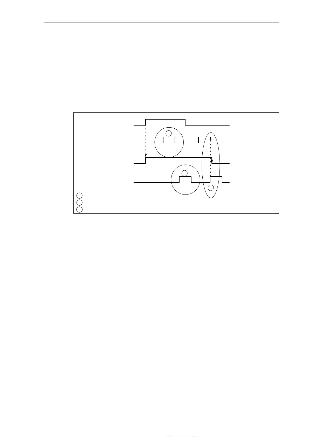
1.3 EMERGENCY STOP acknowlededgement
1.3 EMERGENCY STOP acknowlededgement
Acknowledging EMERGENCY STOP
The EMERGENCY STOP status will only be reset if first the IS “Acknowledge EMERGENCY
STOP” (V2600 0000.2) and then the IS “Reset” (V3000 0000.7) is set. When doing so, make
sure that the IS ”Acknowledge EMERGENCY STOP” and the IS ”Reset” must be set together
at least as long as the IS “EMERGENCY STOP active” (V2700 0000.1) has been reset (see
Fig. 1-1).
IS ”EMERGENCY STOP”
V2600 0000.1
IS ”Acknoweledge
EMERGENCY STOP“
V2600 0000.2
IS ”EMERGENCY STOP
active“
V2700 0000.1
1
2
PLC I/Os
IS ”RESET”
V3000 0000.7
1
The IS ”Acknowledge EMERGENCY STOP” has no effect.
2
The IS ”RESET” has no effect.
The IS ”Acknowledge EMERGENCY STOP” and ”RESET” will reset ”EMERGENCY STOP active.
3
Fig. 1-1 Resetting EMERGENCY STOP
3
Resetting the EMERGENCY STOP status:
resets the IS ”EMERGENCY STOP active”;
connect servo enable;
set the IS ”Position control active“;
set the IS ”802-READY”;
clear alarm 3000;
cancel the part program execution.
The PLC I/Os must be brought again by the PLC user program to the appropriate status required to operate the machine.
Reset
It is not possible to reset the EMERGENCY STOP status with the IS ”Reset” (V3000 0000.7)
alone (see diagram above).
SINUMERIK 802D, 802D base line
6FC5 697-2AA10-0BP2 (11.03) (DF)
1-19
Page 20

EMERGENCY STOP (N2)
1.4 Data descriptions (MD, SD)
Power ON
Power ON (turning off/turning off the power supply) will clear the EMERGENCY STOP status,
except the IS ”EMERGENCY STOP” (V2600 0000.1), which remains set.
1.4 Data descriptions (MD, SD)
Axis-specific machine data
36620 SERVO_DISABLE_DELAY_TIME
MD number Servo enable cutout delay
Default: 0.1 Min. input limit: 0.02 Max. input limit: ***
Change valid after NEW_CONF Protection level: 2/2 Unit: s
Data type: DOUBLE Valid from SW release:
Meaning: Maximum time delay for cancellation of “Servo enable” after faults.
Application example(s) The speed control of the drive should be maintained for this time to make sure that the axis/spindle
Special cases, errors, ...... CAUTION: If the servo enable cutout delay is set too small, the “Servo enable” is already canceled
Related to .... IS ”Servo enable” (V380x 0002.1)
The speed enable (servo enable) of the drive is canceled internally in the control system at the
latest after a set delay time if the axis / spindle is moving.
The entered delay time acts due to the following events:
in case of errors resulting in immediate axis stop
if the IS “Servo enable” is canceled from the PLC.
Once the actual speed reaches the zero speed range (MD 36060: STANDSTILL_VELO_ TOL),
“Servo enable” is disabled for the drive.
The time should be set as large as the axis / spindle needs to come to a standstill from maximum
traversing velocity or speed.
If the axis / spindle is already at a standstill, “Servo enable” is disabled for the drive immediately.
can come to a standstill from maximum traversing velocity or speed. For this time, the cancellation
of “Servo enable” should be delayed for an axis/spindle moving.
even if the axis/spindle is still traversing. In this case, it is suddenly stopped with setpoint 0.
The time set in this MD should therefore be greater than the time of the braking ramp in case of
error statuses (MD 36610: AX_EMERGENCY_STOP_TIME).
MD 36610: AX_EMERGENCY_STOP_TIME (time of braking ramp in case of error statuses)
1-20
SINUMERIK 802D, 802D base line
6FC5 697-2AA10-0BP2 (11.03) (DF)
Page 21

EMERGENCY STOP (N2)
1.5 Signal descriptions
1.5 Signal descriptions
General signals
V2600 0000.1 EMERGENCY STOP
Interface signal Signal(s) to NC (PLC - - -> NC)
Edge evaluation: no Signal(s) updated: cyclically Signal(s) valid from SW release:
Signal state 1 or edge
change 0 - - >1
Signal state 0 or edge
change 1 - - >0
Related to .... IS ”Acknowledge EMERGENCY STOP” (V2600 0000.2)
V2600 0000.2 Acknowledge EMERGENCY STOP
Interface signal Signal(s) to NC (PLC - - -> NC)
Edge evaluation: no Signal(s) updated: cyclically Signal(s) valid from SW release:
Signal state 1 or edge
change 0 - - >1
Related to .... IS ”EMERGENCY STOP” (V2600 0000.1)
The NC is set to the EMERGENCY STOP status and the EMERGENCY STOP sequence in the
NC is started.
The NC is not in the EMERGENCY STOP status.
The EMERGENCY STOP status is (still) active, but can be reset using the IS ”Acknowledge
EMERGENCY STOP” and IS ”Reset”.
IS ”EMERGENCY STOP active” (V2700 0000.1)
The EMERGENCY STOP status will only be reset if first the IS ”Acknowledge EMERGENCY
STOP“ and then the IS ”Reset” (V3000 0000.7) are set. When doing so, make sure that the IS
“Acknowledge EMERGENCY STOP” and the IS ”Reset” must be set together at least as long
as the IS ”EMERGENCY STOP active” (V2600 0000.1) has been reset.
Resetting the EMERGENCY STOP status:
resets the IS ”EMERGENCY STOP active”;
connects “Servo enable”;
sets the IS ”Position control”;
sets the IS ”802-Ready”;
lcears alarm 3000;
aborts the part program execution.
IS ”EMERGENCY STOP active” (V2700 0000.1)
IS ”Reset” (V3000 0000.7)
V2700 0000.1 EMERGENCY STOP active
Interface signal Signal(s) to NC (PLC - - -> NC)
Edge evaluation: no Signal(s) updated: cyclically Signal(s) valid from SW release:
Signal state 1 or edge
change 0 - - >1
Related to .... IS ”EMERGENCY STOP” (V2600 0000.1)
SINUMERIK 802D, 802D base line
6FC5 697-2AA10-0BP2 (11.03) (DF)
The NC is in the EMERGENCY STOP status.
IS ”Acknowledge EMERGENCY STOP” (V2600 0000.2)
1-21
Page 22
EMERGENCY STOP (N2)
1.6 Data fields, lists
1.6 Data fields, lists
1.6.1 Interface signals
Number .Bit Name Ref.
General
V2600 0000 .1 EMERGENCY STOP
V2600 0000 .2 Acknowledge EMERGENCY STOP
V2700 0000 .1 EMERGENCY STOP active
Mode signal range
V3000 0000 .7 Reset K1
1.6.2 Machine data
Number Identifier Name Ref.
Axis-specific
36610 AX_EMERGENCY_STOP_TIME Duration of braking ramp in case of error statuses A3
36620 SERVO_DISABLE_DELAY_TIME Servo enable cutout delay
1-22
SINUMERIK 802D, 802D base line
6FC5 697-2AA10-0BP2 (11.03) (DF)
Page 23

Axis Monitoring (A3)
2.1 Overview of monitoring functions
Motion monitoring functions
- Contour monitoring
- Positioning monitoring
- Zero speed monitoring
- Clamping position monitoring
- Speed setpoint monitoring
- Actual velocity monitoring
- Encoder monitoring functions
Monitoring of static limitations
- Limit switch monitoring
- Work area monitoring
2
SINUMERIK 802D, 802D base line
6FC5 697-2AA10-0BP2 (11.03) (DF)
2-23
Page 24

Axis Monitoring (A3)
2.2 Motion monitoring functions
2.2 Motion monitoring functions
2.2.1 Contour monitoring
Function
The principle of functioning of the contour monitoring is based on the permanent comparison
of measured actual position value and the actual position value calculated from the NC position setpoint. To calculate the following error in advance, a model is used which simulates the
dynamic properties of the position control including feedforward control.
To make sure that the monitoring system does not respond already in the case of slight
speed variations (caused by load changes), a tolerance band is permitted for the maximum
contour deviation.
If the permissible actual value deviation entered in MD 36400: CONTOUR_TOL (contour monitoring tolerance band) is exceeded, an alarm is output, and the axes are stopped.
Activation
Effect
Remedy
The contour monitoring is active for axes and a position-controlled spindle.
If the contour error is too large, the following will occur:
Alarm 25050 ”Contour monitoring” is output.
The axis/spindle concerned is stopped with rapid stop (with open position feedback loop)
via a speed setpoint ramp.
The duration of the braking ramp is defined in the MD 36610: AX_EMERGENCY_STOP_TIME (duration of braking ramp in case of error statuses).
If the axis/spindle interpolates with other axes/spindles, these are stopped by rapid stop
with reduction of the following error (position setpoint = constant).
Increase tolerance band of monitoring function in MD 36400.
The real servo gain factor must correspond to the desired servo gain factor set in
MD 32200: POSCTRL_GAIN (servo gain factor).
With an analog spindle, check
MD 32260: RATED_VELO (rated motor speed) and
MD 32250: RATED_OUTVAL (rated output voltage).
2-24
Check optimization of speed controller.
Check smooth running of axes.
Check machine data for traversing movements (feedoverride, acceleration, max. veloci-
ties, ... )
SINUMERIK 802D, 802D base line
6FC5 697-2AA10-0BP2 (11.03) (DF)
Page 25
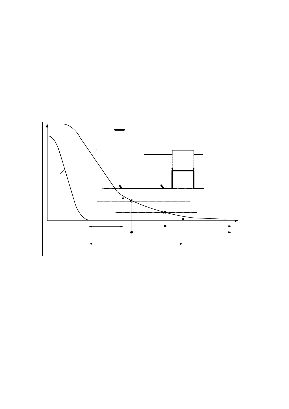
2.2.2 Positioning monitoring
Function
To make sure that an axis is positioned within a specified time, the time configured in MD
36020: POSITIONING_TIME (exact stop fine time delay) is started after a motion block has
been ended (set point has reached the target), and after this time has elapsed, it is checked
whether the axis has reached its set position within the tolerance of MD 36010: STOP_LIMIT_FINE (exact stop fine).
”Exact stop coarse and fine“ see:
References: Chapter ”Continuous -Path Mode, Exact Stop and LookAhead”
Axis Monitoring (A3)
2.2 Motion monitoring functions
V or s
active tolerance in case of zero
speed or clamping monitoring
Actual value
Setpoint
MD:
STANDSTILL_
DELAY_TIME
MD: POSITIONING_TIME
Fig. 2-1 Interrelation between positioning, zero speed and clamping monitoring
Interface signal
”Clamping process
running“ (V380x
0002.3)
MD: CLAMP_POS_TOL
MD:
STANDSTILL_POS_T
OL
MD: STOP_LIMIT_COARSE
MD: STOP_LIMIT_FINE
“Exact stop fine” - interface signal
“Exact stop coarse“ - interface signal
t
Enabling
The positioning monitoring is always enabled after a “setpoint-dependent” completion of motion blocks (setpoint has reached the target).
The positioning monitoring is active for axes and a position-controlled spindle.
Disabling
The positioning monitoring is disabled after the specified ”Exact stop limit fine” has been reached or after output of a new setpoint position (e.g. when positioning to ”Exact stop coarse“
followed by a block change).
SINUMERIK 802D, 802D base line
6FC5 697-2AA10-0BP2 (11.03) (DF)
2-25
Page 26

Axis Monitoring (A3)
2.2 Motion monitoring functions
Effect
If the limit value for “Exact stop fine” has not yet been reached after the positioning monitoring time has elapsed, the following action is carried out:
Alarm 25080 ”Positioning monitoring” is output.
The axis/spindle concverned is stopped with rapid stop (with open position control loop)
via a speed setpoint ramp.
The duration of the braking ramp is defined in MD 36610: AX_EMERGENCY_STOP_TIME (duration of braking ramp in case of error statuses).
If the axis/spindle interpolates with other axes/spindles, these will be stopped by rapid
stop with reduction of the following error (specification of partial position setpoint = 0).
Error cause/error elimination
Too small position controller gain - -> change machine data for position control gain
MD 32200: POSCTRL_GAIN(servo gain factor)
Positioning window (exact stop fine), positioning monitoring time and position control gain
are not matched another to one - -> change machine data:
MD 36010: STOP_LIMIT_FINE (exact stop fine),
MD 36020: POSITIONING_TIME (exact stop fine delay time),
MD 32200: POSCTRL_GAIN (servo gain factor)
General rule
Large positioning window - -> a relative short max. positioning monitoring time can be
selected
Small positioning window - -> a relatively long positioning monitoring time must be selec-
ted
Small position control gain - -> a relatively long max. positioning monitoring time must
be selected
High position control gain - -> a relatively short max. positioning monitoring time can be
selected
Note
The size of the positioning window will influence the block change time. The smaller these tolerances are chosen, the longer will last the positioning process and the longer it will last until the next
command can be executed.
2-26
SINUMERIK 802D, 802D base line
6FC5 697-2AA10-0BP2 (11.03) (DF)
Page 27

2.2.3 Zero speed monitoring
Function
After a motion block has been completed (position setpoint has reached target), it is monitored whether the axis is no more away from its setpoint position than specified in MD 36060:
STANDSTILL_POS_TOL (standstill tolerance) after the delay time that can be parameterized
in MD 36040: STANDSTILL_DELAY_TIME (standstill monitoring delay time) has elapsed.
Otherwise, an alarm is generated.
See Fig. 2-1
Activation
The zero speed monitoring is always active after the “Standstill monitoring delay time” has
elapsed, provided that no new traversing command is active.
The standstill monitoring is active for axes and a position-controlled spindle.
Axis Monitoring (A3)
2.2 Motion monitoring functions
Effect
The response of the monitoring function has the following effect:
Alarm 25040 ”Standstill monitoring” is output.
The axis/spindle concerned is stopped with rapid stop (with open position control loop) via
a speed setpoint ramp. The duration of the braking ramp is defined in MD
36610: AX_EMERGENCY_STOP_TIME (duration of braking ramp in case of error statuses).
If the axis interpolates with other axes/spindles, these will be stopped by rapid stop with
reduction of the following error (specification of partial position setpoint = 0).
Error cause/error elimination
Position control gain too large (vibrations of servo loop) - ->change machine data for con-
troller gain MD 32200: POSCTRL_GAIN (servo gain factor)
Standstill window too small - -> change machine data
MD 36030: STANDSTILL_POS_TOL (standstill tolerance)
Axis is mechanically pushed off position - -> eliminate cause
2.2.4 Clamping monitoring
Function
If you wish the axis to be clamped at the end of the positioning process, the clamping monitoring can be activated using the IS “Clamping monitoring running” (V380x 0002.3).
SINUMERIK 802D, 802D base line
6FC5 697-2AA10-0BP2 (11.03) (DF)
2-27
Page 28

Axis Monitoring (A3)
2.2 Motion monitoring functions
This can be necessary because it is possible that during the clamping process the axis has
been pushed off its setpoint position farther than permitted by the standstill tolerance. The
amount by which the setpoint position can be left is specified in MD 36050:
CLAMP_POS_TOL (clamping position tolerance at interface signal “Clamping running“).
See Fig. 2-1
Activation
The clamping position monitoring is activated by the interface signal ”Clamping process running”. It replaces the standstill monitoring during the clamping process.
The clamping position monitoring is active for axes and a position-controlled spindle.
Effect
If during the clamping process the axis is pushed off its position farther than permitted by the
clamping position tolerance, the following will occur:
Alarm 26000 ”Clamping position monitoring” is output.
The axis/spindle concerned is stopped with rapid stop (with open position control loop) via
a speed setpoint ramp. The duration of the braking ramp is defined in
MD 36610: AX_EMERGENCY_STOP_TIME (duration of braking ramp in case of error
statuses).
If the axis/spindle interpolates with other axes/spindles, these will also be stopped by ra-
pid stop with reduction of the following error (specification of partial position setpoint = 0).
2.2.5 Speed setpoint monitoring
Function
The speed setpoint monitoring checks whether the setpoint specification does not exceed the
maximum permissible speed for the drives specified in MD 36210: CTRLOUT_LIMIT (maximum speed setpoint). If necessary, it is limited to this value, and the axis/spindle is stopped
and an alarm is output.
For the axes, the maximum speed setpoint (as a percentage) is above the speed at which the
velocity defined in MD 3200: MAX_AX_VELO is reached (100%). This also defines the control margin.
With an analog spindle, the maximum output speed cannot be greater than the speed reached at a maximum setpoint output voltage of 10V (100%).
2-28
The speed setpoint consists of the speed setpoint of the position controller and the feedforward control value (if feedforward control is active).
SINUMERIK 802D, 802D base line
6FC5 697-2AA10-0BP2 (11.03) (DF)
Page 29

Feedforward control value
Axis Monitoring (A3)
2.2 Motion monitoring functions
Activation
Effect
Following
error
Fig. 2-2 Speed setpoint monitoring
KV
Position controller
+
Speed setpoint
monitoring
to speed
controller
The speed setpoint monitoring is always active for axes and for a spindle.
The following will occur if the maximum speed setpoint is exceeded:
Alarm 25060 ”Speed setpoint limitation” is output.
The axis/spindle concerned is stopped with rapid stop (with open position control loop) via
a speed setpoint ramp.
The duration of the braking ramp is defined in MD 36610: AX_EMERGENCY_STOP_TIME (duration of braking ramp in case of error statuses).
If the axis interpolates with other axes/spindles, these will be stopped by rapid stop with
reduction of the following error (specification of partial position setpoint = 0).
Error causes
Note: At the access level “Expert mode” (protection level 1), a delay time can be set in
MD 36220: CTRLOUT_LIMIT_TIME, after which the alarm is generated, stopping the axes.
This time is zero by default.
The beginning limitation of the speed setpoint makes this servo loop non-linear. Generally,
this results in path deviations when an axis dwells in a speed setpoint limitation. Therefore, a
control margin must be set (see Section 3.3.4 “Speed setpoint output”).
A measuring error circuit or a drive error exists in the measuring circuit.
Too high setpoints specified (accelerations, velocities, reduction factors)
Obstacle in working area (e.g. coming into contact with the work table)
Tachogenerator adjustment with analog spindle has not been carried out correctly or a
measuring circuit or drive error exists.
SINUMERIK 802D, 802D base line
6FC5 697-2AA10-0BP2 (11.03) (DF)
2-29
Page 30

Axis Monitoring (A3)
2.2 Motion monitoring functions
2.2.6 Actual velocity monitoring
Function
The actual velocity is monitored for exceeding of a permissible limit value entered in MD
36200: AX_VELO_LIMIT (threshold value for velocity monitoring).
Activation
The actual velocity monitoring is always active if the active measuring circuit that has been
activated via the iS “Position measuring system 1” (V380x 0001.5) provides actual values, i.e.
is still below the imit frequency.
The actual velocity momnitoring is active for axes and for a spindle.
Effect
The following will occur if the “Threshold value for velocity monitoring” is exceeded:
Alarm 25030 ”Actual velocity alarm limit”
The axis/spindle concerned is stopped with rapid stop (with open position control loop) via
a speed setpoint ramp.
The duration of the brake ramp is defined in MD 36610: AX_EMERGENCY_STOP_TIME
(duration of braking ramp in case of error statuses).
If the axis/spindle interpolates with other axes/spindles, these will also be stopped by ra-
pid stop with reduction of the following error (specification of partial setpoint = 0).
Notes for fault finding
Check actual values.
Check position control direction.
Check MD 36200: AX_VELO_LIMIT (threshold value for velocity monitoring).
In the case of an analog spindle, check speed setpoint cable.
2-30
SINUMERIK 802D, 802D base line
6FC5 697-2AA10-0BP2 (11.03) (DF)
Page 31

2.3 Encoder monitoring functions
2.3.1 Encoder limit frequency monitoring
Function
If the limit frequency of a measuring system, which is entered in MD 36300: ENC_FREQ_LIMIT(encoder limit frequency), is exceeded, the position synchronization (reference point) between machine and control system will be lost. A correct position control is no longer possible
in this cases. This status is signaled to the PLC.
Activation
The encoder limit frequency monitoring is always active if the encoder is turned on and is
active for axes and for a spindle.
Axis Monitoring (A3)
2.3 Encoder monitoring functions
Effect
The following will occur if the limit frequency of an encoder is exceeded:
The IS “Encoder limit frequency exceeded 1” (V390x 0000.2) is set.
Spindle continues running withspeed control
If the spindle speed is reduced such that the encoder frequency falls below the value specified in MD 36302: ENC_FREQ_LIMIT_LOW (% value of MD 36300: ENC_FREQ_LIMIT), the spindle will automatically resynchronize with the reference system of the encoder.
If with an active measuring system of a position-controlled axis/spindle, the limit fre-
quency is exceeded, alarm 21610 ”Frequency exceeded” is output.
The axis/spindle concerned is stopped with rapid stop (with open position control loop) via
a speed setpoint ramp.
The duration of the brake ramp is defined in MD 36610: AX_EMERGENCY_STOP_TIME
(duration of braking ramp in case of error statuses).
If the axis/spindle interpolates with other axes/spindles, these will also be stopped by ra-
pid stop with reduction of the following error (specification of partial setpoint = 0).
Error elimination
After the axes have come to a standstill, the position control will resume automatically.
Note
The axis concerned must be rereferenced.
SINUMERIK 802D, 802D base line
6FC5 697-2AA10-0BP2 (11.03) (DF)
2-31
Page 32

Axis Monitoring (A3)
2.3 Encoder monitoring functions
2.3.2 Zero mark monitoring
Function
The zero mark monitoring checks whether pulses have been lost between two zero mark
passages of the position actual-value encoder. The number of detected zero mark errors at
which the monitoring function is to respond is entered in MD 36310: ENC_ZERO_MONITORING (zero mark monitoring).
Activation
The monitoring is activated using MD 36310: ENC_ZERO_MONITORING.
The counting of the zero mark errors starts from zero after the encoder has been turned on.
Effect
If the number of the zero mark errors entered in MD 36310: ENC_ZERO_MONITORING is
reached for a measuring system, alarm 25020 ”Zero mark monitoring” is output.
Error causes
The axis/spindle concerned is stopped with rapid stop (with open position control loop) via a
speed setpoint ramp.
The duration of the brake ramp is defined in MD 36610: AX_EMERGENCY_STOP_TIME
(duration of braking ramp in case of error statuses).
If the axis/spindle interpolates with other axes/spindles, these will also be stopped by rapid
stop with reduction of the following error (specification of partial setpoint = 0).
MD 36300: ENC_FREQ_LIMIT (encoder limit frequency) set too high.
Encoder cable damaged.
Encoder or encoder electronics defective.
Note
In case of an error, the IS “Referenced/synchronized 2” (V390x 0000.4) is canceled, i.e. the axis
must be rereferenced.
2-32
SINUMERIK 802D, 802D base line
6FC5 697-2AA10-0BP2 (11.03) (DF)
Page 33

2.4 Monitoring of static limitations
2.4.1 Limit switch monitoring
Axis Monitoring (A3)
2.4 Monitoring of static limitations
2nd SW limit switch
(activated via PLC)
Fig. 2-3 Overview of limit stops of a linear axis
Hardware limit switches
Function
For each axis, one hardware limit switch each is provided for each traversing direction to prevent the slide moving off the slide bed.
If the hardware limit switch is overtraveled, the PLC will signal it to the NC via the IS ”Hardware limit switch plus/minus” (V380x 1000.1 or .0), and the movement of all axes is stopped.
The kind of braking can be defined via the MD 36600: BRAKE_MODE_CHOICE (braking behavior with hardware limit switch).
Activation
The hardware limit switch monitoring is active in all operating modes after the control system
has powered up.
1st SW limit switch
HW limit switch
Mechanical
traversing stop
EMERGENCY STOP
Effect
When a hardware limit switch is overtraveled, depending on the direction, alarm 21614
”Hardware limit switch + or -” is output.
Depending on MD 36600: BRAKE_MODE_CHOICE (braking behavior with hardware limit
switch), the axis is stopped.
If the axis/spindle interpolates with other axes/spindles, these will also be stopped, depen-
ding on MD 36600: BRAKE_MODE_CHOICE (braking behavior with hardware limit
switch).
The direction keys in the direction of approach are disabled.
SINUMERIK 802D, 802D base line
6FC5 697-2AA10-0BP2 (11.03) (DF)
2-33
Page 34

Axis Monitoring (A3)
2.4 Monitoring of static limitations
Remedy
Initiate Reset.
Retract in the opposite direction (in JOG mode).
Correct the program.
Software limit switches
Function
The software limit switches serve as limitations of the maximum traversing range of each individual axis.
2 software limit switch pairs are provided per axis, which are defined via the following machine data in the machine axis system:
MD 36100: POS_LIMIT_MINUS (1st software limit switch minus)
MD 36110: POS_LIMIT_PLUS (1st software limit switch plus)
MD 36120: POS_LIMIT_MINUS2 (2nd software limit switch minus)
MD 36130: POS_LIMIT_PLUS2 (2nd software limit switch plus)
Activation
The software limit switch monitoring is active in all operating modes after reference point
The position of the software limit switches can be approached.
The 2nd software limit switch can be activated from the PLC via the interface signal ”2nd
The SW limit switch monitoring is not active with endlessly rotating rotary axes, i.e. if
Effect/reactions
Depending on the operating mode, there are different reactions if it was tried to overtravel a
software limit switch:
AUTO, MDA:
JOG:
approach.
software limit switch plus/minus” (V380x 1000.3 or .2). The change will come into effect
immediately. The 1st software limit switch plus/minus is thus inactive.
MD 30310: ROT_IS_MODULO = 1. (modulo conversion for rotary axis and spindle)
- The block that would violate the software limit switches will not start. The previous
block is completed correctly.
- The program execution is canceled.
- Alarm 10720 ”Software limit switch + or -” is output.
2-34
- The axis is stopped at the software limit switch position.
- Alarm 10621 ”Axis has stopped on software limit switch + or -”.
- The direction keys in the direction of approach are disabled.
SINUMERIK 802D, 802D base line
6FC5 697-2AA10-0BP2 (11.03) (DF)
Page 35

Special features:
- Switching over the software limit switch:
If the current position after switching over lies after the new software limit switch, the
axis is decelerated at the maximum permissible acceleration. If the axis interpolates
with other axes, these will also be decelerated. A contour violation may result.
Remedy
Initiate Reset.
Retract in the opposite direction (in JOG mode).
Correct the program.
2.4.2 Working area limitation
Function
Axis Monitoring (A3)
2.4 Monitoring of static limitations
Working area limitations describe the range in which a machining can be carried out. In addition to the limit switches, the working area limitation is another means for the user to limit the
traversing range of the axes.
References: ”Operation and Programming“.
It is monitored whether the tool tip P is within the protected working area. The value entered
in the working area limitation is the last permissible position for the axis.
Using MD 21020: WORKAREA_WITH_TOOL_RADIUS (taking into account the tool radius in
the case of working area limitation), it can be determined whether the tool radius is taken into
account in the monitoring.
One pair of values (minus/plus) can be specified per axis to describe the protected working
area.
Specifying the working area limitation
The working area limitation can be specified and modified in two different ways:
via the operator panel in the “Parameters” operating area using the following setting data:
SD 43430: WORKAREA_LIMIT_MINUS (working area limitation minus)
SD 43420: WORKAREA_LIMIT_PLUS (working area limitation plus)
Any changes in Automatic mode are only possible in the Reset status and will then come
into effect immediately.
In Jog mode, changes are always possible, but come only into effect when a new movement starts.
in the program with G25/G26. Any changes come into effect immediately.
A programmed limitation has first priority; it will overwrite the value entered in the setting
data and is kept after RESET and program end.
SINUMERIK 802D, 802D base line
6FC5 697-2AA10-0BP2 (11.03) (DF)
2-35
Page 36

Axis Monitoring (A3)
2.4 Monitoring of static limitations
X
Machine
G26
X
max
M
G25
X
min
Fig. 2-4 Working area limitation shown using the example of a turning machine
Tool tip
Working area
Z
W
G25
Z
min
G26
Z
max
Machine
Activation
Using SD 43410: WORKAREA_MINUS_ENABLE, SD 43400: WORKA-
During the program execution, the working area limitation can be activated using the mo-
The working area limitation is not active with endlessly rotating rotary axes, i.e. if MD
Effect/reaction
Depending on the operating mode, there are different reactions if it has been tried to overtreavel the work area limitation:
AUTO, MDA:
JOG:
REA_PLUS_ENABLE (working area limitation in the negative or positive direction active),
it is possible to activate the working area limitation; it comes into effect after reference
point approach.
dal G codes ”WALIMON” and deactivated using ”WALIMOF”.
30310: ROT_IS_MODULO = 1 (modulo conversion for rotary axis and spindle).
- The block that violates the working area limitation is not started. The previous block is
still completed correctly.
- The program execution is aborted.
- Alarm 10730 ”Working area limitation + or - ” is set.
2-36
- The axis stops at the position of the working area limitation.
- Alarm 10631 ”Axis stopped at working area limitation + or -” is set.
- The direction keys in the direction of approach are disabled.
SINUMERIK 802D, 802D base line
6FC5 697-2AA10-0BP2 (11.03) (DF)
Page 37

Remedy
Initiate Reset.
Check the working area limitation in the part program (G25/G26) or in the setting data.
Move away in the opposite direction (in JOG mode).
2.5 Boundary conditions
To make sure that the monitoring functions respond correctly, make especially sure that the
machine data are correct:
MD 31030: LEADSCREW_PITCH (leadscrew pitch)
Gear transmission ratio (load gear):
MD 31050: DRIVE_AX_RATIO_DENOM(load gear denominator)
MD 31060: DRIVE_AX_RATIO_NUMERA(load gear numerator)
Gear transmission ratio (encoder), also for spindle if any:
MD 31070: DRIVE_ENC_RATIO_DENOM (resolver gearbox denominator)
MD 31080: DRIVE_ENC_RATIO_NUMERA (resolver gearbox denominator)
Axis Monitoring (A3)
2.5 Boundary conditions
MD 32810: EQUIV_SPEEDCTRL_TIME
(speed control loop equivalent time constant for feedforward control)
Ratio output voltage / output speed
(only applicable to analog spindle):
MD 32260: RATED_VELO (rated motor speed)
MD 32250: RATED_OUTVAL (rated output voltage)
Encoder resolution
The corresponding machine data are described in
References: Chapter ”Velocities, Setpoint/Actual- Value Systems, Closed-Loop Control”
SINUMERIK 802D, 802D base line
6FC5 697-2AA10-0BP2 (11.03) (DF)
2-37
Page 38

Axis Monitoring (A3)
2.6 Data descriptions (MD, SD)
2.6 Data descriptions (MD, SD)
2.6.1 Channel -specific machine data
21020 WORKAREA_WITH_TOOL_RADIUS
MD number Taking into account the tool radius with working area limitation
Default: 0 Min. input limit: 0 Max. input limit: 1
Change valid after RESET Protection level: 2/2 Unit: Data type: BOOLEAN Valid from SW release:
Meaning: 0: The tool radius is not taken into account.
2.6.2 Axis/spindle -specific machine data
36000 STOP_LIMIT_COARSE
MD number Exact stop coarse
Default: 0.04 Min. input limit: 0.0 Max. input limit: ***
Change valid after NEW_CONF Protection level: 2/2 Unit: mm, degrees
Data type: DOUBLE Valid from SW release:
Meaning: An NC block is considered completed if the actual position of the path axes is away from the
Special cases, errors, ...... This MD may not be less than MD 36010: STOP_LIMIT_FINE (exact stop fine). To achieve the
Related to .... MD 36020: POSITIONING_TIME (exact stop fine delay time)
1: The tool radius is taken into account in the working area limitation.
setpoint position by the value of the entered exact stop limit. If the actual position of a path axis
is not within this limit, the NC block is not considered completed and the part program cannot be
continued. The time when the next block is processed depends on the size of the value entered.
The larger the value is, the earlier is the block change initiated. If the specified exact stop limit is
not reached,
- the block is not considered completed;
- the axis cannot be traversed further;
- the alarm 25080 “Positioning monitoring” is output after the time defined in
MD 36020: POSITIONING_TIME (exact stop fine monitoring time) has elapsed;
- the direction of movement +/ - is displayed for the axis on the position display. The eaxt stop
window is also evaluated for spindles in the position-controlled mode.
same block change behavior as with the exact stop fine criterion, the exact stop coarse window
may be identical to the exact stop fine window.
This MD may not be equal to or greater than MD 36030: STANDSTILL_POS_TOL (standstill
position tolerance).
36010 STOP_LIMIT_FINE
MD number Exact stop fine
Default : 0.01 Min. input limit: 0.0 Max. input limit: ***
Change valid after NEW_CONF Protection level: 2/2 Unit: mm, degrees
Data type: DOUBLE Valid from SW release:
Meaning: See MD 3600: STOP_LIMIT_COARSE (exact stop coarse)
Special cases, errors, ...... This MD may not be greater than MD 36000: STOP_LIMIT_COARSE (exact stop coarse).
Related to .... MD 36020: POSITIONING_TIME (exact stop fine delay time)
2-38
This MD may not be equal to or greater than MD 36030: STANDSTILL_POS_TOL (standstill
position tolerance).
SINUMERIK 802D, 802D base line
6FC5 697-2AA10-0BP2 (11.03) (DF)
Page 39
Axis Monitoring (A3)
2.6 Data descriptions (MD, SD)
36020 POSITIONING_TIME
MD number Time delay for exact stop fine
Default: 1.0 Min. input limit: 0.0 Max. input limit: ***
Change valid after NEW_CONF Protection level: 2/2 Unit: s
Data type: DOUBLE Valid from SW release:
Meaning: This MD is used to specify the time after which the following error must have reached the limit
Related to .... MD 36010: STOP_LIMIT_FINE (exact stop fine)
36030 STANDSTILL_POS_TOL
MD number Standstill position tolerance
Default: 0.2 Min. input limit: 0.0 Max. input limit: ***
Change valid after NEW_CONF Protection level: 2/2 Unit: mm, degrees
Data type: DOUBLE Valid from SW release:
Meaning: On completion of a traversing block (position setpoint has reached target), it is monitored whe-
Special cases, errors, ...... The standstill tolerance must be greater than the “Exact stop limit coarse”.
Related to .... MD 36040: STANDSTILL_DELAY_TIME (standstill monitoring delay time)
value for exact stop fine after the time for approaching the position has elapsed (partial position
set value=0 at the end of the movement). If this is not the case, the alarm 25080 ”Positioning
monitoring” is set and the axis concerned is decelerated.
The MD should be selected so generously that the monitoring does not respond in normal mode,
since the entire traversing process (acceleration, constant traversing, braking) is monitored by
other functions continuously.
ther the axis is no farther away from its set position than specified in
MD 36060: STANDSTILL_POS_TOL (standstill tolerance) after the parameterizable delay time
defined in MD 36040 STANDSTILL_DELAY_TIME (standstill monitoring delay time) has elapsed.
If the standstill position tolerance exceeds or falls below the set position, alarm 25040 ”Standstill
monitoring” is output and the axis is stopped.
36040 STANDSTILL_DELAY_TIME
MD number Standstill monitoring delay time
Default: 0.4 Min. input limit: 0.0 Max. input limit: ***
Change valid after NEW_CONF Protection level: 2/2 Unit: s
Data type: DOUBLE Valid from SW release:
Meaning: see MD 36030: STANDSTILL_POS_TOL (standstill position tolerance)
Related to .... MD 36030: STANDSTILL_POS_TOL (standstill position tolerance)
36050 CLAMP_POS_TOL
MD number Clamping tolerance at interface signal ”Clamping active“
Default: 0.5 Min. input limit: 0.0 Max. input limit: ***
Change valid after NEW_CONF Protection level: 2/2 Unit: mm; degrees
Data type: DOUBLE Valid from SW release:
Meaning: The interface signal ”Clamping process running” (V380x0002.3) activates clamping monitoring. If
Special cases, errors, ...... The clamping tolerance must be greater than the “Exact stop limit coarse”.
Related to .... IS ”Clamping process running“
the monitored axis is pushed off the set position (exact stop limit) more than specified in the
clamping tolerance, alarm 26000 ”Clamping monitoring” is generated and the axis stopped.
SINUMERIK 802D, 802D base line
6FC5 697-2AA10-0BP2 (11.03) (DF)
2-39
Page 40

Axis Monitoring (A3)
2.6 Data descriptions (MD, SD)
36060
MD number
Default: 5.0 mm/min,
0.0138 rpm
Change valid after NEW_CONF Protection level: 2/2 Unit:
Data type: DOUBLE Valid from SW release:
Meaning: This machine date defines the standstill area for the axis velocity and/or for spindle speed.
Application example(s) In order to allow a controlled stop of the axis/spindle, the pulse enable should only be canceled if
Related to .... IS ”Axis/spindle at a standstill” (V390x0001.4)
36100 POS_LIMIT_MINUS
MD number 1st software limit switch minus
Default: - 100 000 000 Min. input limit: *** Max. input limit: ***
Change valid after Power On Protection level: 2/7 Unit: mm; degrees
Data type: DOUBLE Valid from SW release:
Meaning: The same meaning as the 1st software limit switch plus, but for the traversing area limit in the
MD inapplicable if ...... the axis is not referenced.
Related to .... IS ”2nd software limit switch minus”
STANDSTILL_VELO_TOL
Max. velocity/speed ”Axis/spindle at a standstill“
Min. input limit: 0.0 Max. input limit: ***
Linear axis: mm/min
Rotary axis: rpm
If the current actual velocity of the axis and/or the actual speed of the spindle is less than the
value entered and if the NC does no longer deliver setpoints to the axis/spindle, the
IS ”Axis/spindle at a standstill” (V390x0001.4) is set.
V
act
V
still
1
0
the axis/spindle has stopped. Otherwise, the axis would coast down.
negative direction.
The MD is active after reference point approach if the PLC interface signal
”2nd software limit switch minus” is not set.
IS
MD:STANDSTILL_VELO_TOL
Spindle at a standstill
t
36110 POS_LIMIT_PLUS
MD number 1st software limit switch plus
Default: 100 000 000 Min. input limit: *** Max. input limit: ***
Change valid after Power On Protection level: 2/7 Unit: mm; degrees
Data type: DOUBLE Valid from SW release:
Meaning: In addition to the hardware switch, it is also possible to use a software switch. The absolute posi-
MD inapplicable if ...... the axis is not referenced.
Related to .... IS ”2nd software limit switch plus”
tion in the machine coordinate system of the positive traversing limit is entered in this MD for
each axis.
The MD is active after reference point approach if the IS ”2nd software limit switch plus” is not
set.
2-40
SINUMERIK 802D, 802D base line
6FC5 697-2AA10-0BP2 (11.03) (DF)
Page 41

Axis Monitoring (A3)
2.6 Data descriptions (MD, SD)
36120 POS_LIMIT_MINUS2
MD number 2nd software limit switch minus
Default: - 100 000 000 Min. input limit: *** Max. input limit: ***
Change valid after Power On Protection level: 2/7 Unit: mm; degrees
Data type: DOUBLE Valid from SW release:
Meaning: The same meaning as the 2nd software limit switch plus, but for the traversing area limit in the
MD inapplicable if ...... the axis is not referenced.
Related to .... IS ”2nd software limit switch minus”
36130 POS_LIMIT_PLUS2
MD number 2nd software limit switch plus
Default: 100 000 000 Min. input limit: *** Max. input limit: ***
Change valid after Power On Protection level: 2/7 Unit: mm; degrees
Data type: DOUBLE Valid from SW release:
Meaning: This machine data can be used to specify a 2nd software limit switch position in the machine
MD inapplicable if ...... the axis is not referenced.
Related to .... IS ”2nd software limit switch plus”
negative direction.
Which of the two SW limit switches 1 or 2 is to be active can be selected from the PLC using the
interfrace signal.
e. g. V380x1000 bit 2 = 0 ”1st software limit switch minus” active for 1st axis
Bit 2 = 1 ”2nd software limit switch minus” active for 1st axis
axis system in the positive direction.
Which of the two software limit switches 1 or 2 is to be active can be selected from the PLC
using the interface signal.
e. g.: V380x1000 Bit 3 = 0 ”1st software limit switch plus” active for the 1st axis
Bit 3 = 1 ”2nd software limit switch plus” active for 1st axis
36200 AX_VELO_LIMIT[0]....[5]
MD number Threshold value for velocity monitoring
Default: 11500 mm/min,
31.944 rpm
Change valid after NEW_CONF Protection level: 2/7 Unit: mm/min
Data type: DOUBLE Valid from SW release:
Meaning: This MD is used to specify the threshold value of the actual-value velocity monitoring.
If the axis has at least one active encoder and this is below its limit frequency, alarm 25030 “Actual velocity alarm limit” is output if the threshold value is exceeded, and the axes are stopped.
Settings:
For axes, select a value that is 10-15 % higher than
MD 32000: MAX_AX_VELO (max. axis velocity).
For spindles, select a value per gear stage, which is 10-15 % higher than
MD 35110: GEAR_STEP_MAX_VELO_LIMIT[n] (max. gear stage speed).
The machine data index is coded as follows:
[control parameter block No.]: 0-5
For the activation of the control parameter records, please refer to:
References: Section ”Velocities, Setpoint/Actual - Value Systems, Closed- Loop Control“
Min. input limit: 0.0 Max. input limit: ***
rpm
SINUMERIK 802D, 802D base line
6FC5 697-2AA10-0BP2 (11.03) (DF)
2-41
Page 42

Axis Monitoring (A3)
2.6 Data descriptions (MD, SD)
36300 ENC_FREQ_LIMIT[0]
MD number Encoder limit frequency
Default: 300000 Min. input limit: 0.0 Max. input limit: ***
Change valid after Power On Protection level: 2/2 Unit: Hz
Data type: DOUBLE Valid from SW release:
Meaning: This MD is used to specify the encoder limit frequency.
The active encoder is defined via the IS ”Position measuring system 1” (V380x0001.5).
Related to .... MD 36302: ENC_FREQ_LIMIT_LOW
36310 ENC_ZERO_MONITORING[0]
MD number Zero mark monitoring
Default: 0 Min. input limit: 0 Max. input limit: ***
Change valid after NEW_CONF Protection level: 2/2 Unit: Data type: DWORD Valid from SW release:
Meaning: This machine data is used to activate the zero reference mark monitoring and to define the num-
Examples: MD value = 1: The monitoring will respond at the 1st error.
Special cases, errors, ...... For absolute encoders, the zero mark monitoring must be disabled with the value = 0!
ber of illegal zero reference mark errors.
0: Zero mark monitoring OFF, encoder HW monitoring ON
1-99, > 100: Number of detected zero mark errors at which the monitoring is to respond
100: Zero mark monitoring OFF, encoder HW monitoring OFF
MD value = 2: The 1st error is tolerated. The monitoring will respond at the 2nd error.
MD value = 3: The 1st and 2nd errors are tolerated. At the 3rd error, the monitoring will respond.
After turning on the encoder, the error count will always start from zero.
36400 CONTOUR_TOL
MD number Contour monitoring tolerance band
Default: 1.0 Min. input limit: 0.0 Max. input limit: ***
Change valid after NEW_CONF Protection level: 2/2 Unit: mm; degrees
Data type: DOUBLE Valid from SW release:
Meaning: The tolerance band for maximum contour deviation.
Further references see Section 2.2.1
36600 BRAKE_MODE_CHOICE
MD number Braking behavior with hardware limit switch
Default: 1 Min. input limit: 0 Max. input limit: 1
Change valid after Power On Protection level: 2/2 Unit: Data type: BYTE Valid from SW release:
Meaning: If with a traversing axis a rising edge of the axis-specific hardware switch is detected, the axis is
Related to .... IS ”Hardware limit switch plus or minus” (V380x1000.1 or V380x1000.0)
The admissible deviation between the real and the expected actual value is entered in this MD.
The input of a tolerance band is intended to avoid false trippings of the contour monitoring due to
slight speed variations resulting from process-related control operations (e.g. on first cut).
This MD has to be adapted to the position controller gain and, in case of feedforward control, to
the accuracy of the line motion model MD 32810: EQUIV_SPEEDCTRL_TIME (equivalent time
constant for feedforward control of speed control loop) and to the permissible accelerations and
velocities.
decelerated immediately.
The deceleration mode is set in the machine data:
0: Controlled braking according to the acceleration ramp defined by
MD 32300: MAX_AX_ACCEL (axis acceleration).
1: Rapid deceleration (specification of setpoint = 0) with reduction of the following error
2-42
SINUMERIK 802D, 802D base line
6FC5 697-2AA10-0BP2 (11.03) (DF)
Page 43
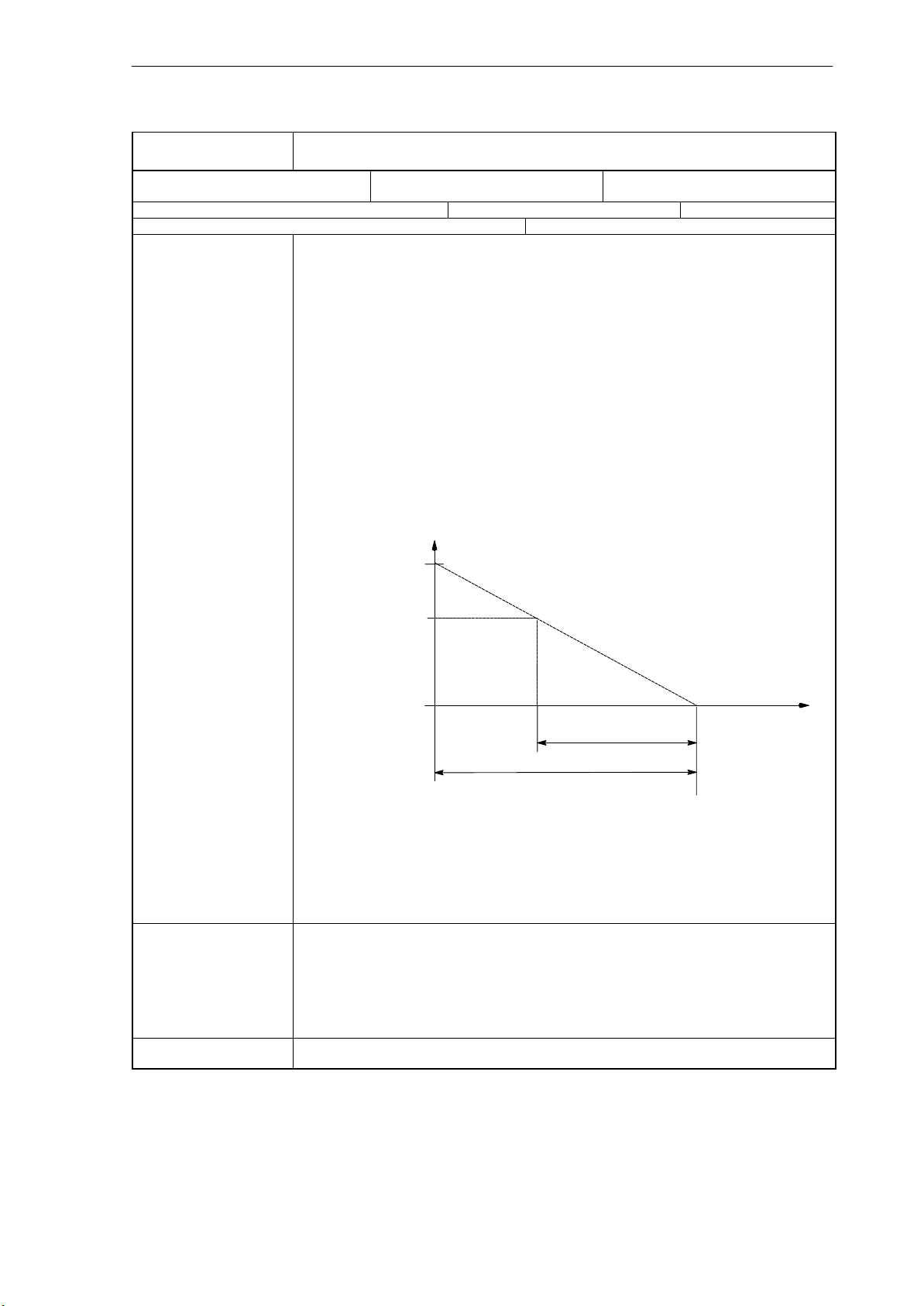
Axis Monitoring (A3)
2.6 Data descriptions (MD, SD)
36610
MD number Duration of brake ramp in case of errors
Default: 0.05 Min. input limit: 0.02 Max. input limit: 1000
Change valid after NEW_CONF Protection level: 2/2 Unit: s
Data type: DOUBLE Valid from SW release:
Meaning: For axis: The axis concerned is stopped with rapid stop (with open position control loop) via a
AX_EMERGENCY_STOP_TIME
brake ramp of the speed setpoint if the monitoring functions listed below respond:
EMERGENCY STOP
Following error monitoring
Positioning monitoring
Zero-speed control
Clamping monitoring
Set speed monitoring
Actual velocity monitoring
Encoder limit frequency monitoring (except for speed-controlled spindles)
Zero mark monitoring
Contur tunnel monitoring
If the encoder limit frequency is exceeded, the speed setpoint is displayed in the NC basic
screen as an actual value.
Enter the time needed to reduce the speed setpoint from the maximum speed setpoint to setpoint = 0 in MD 36610. The time until standstill depends on the current speed setpoint if a monitoring function responds.
Speed setpoint
MD 36210:
CTRLOUT_LIMIT
e.g. current
speed setpoint
Current time until
axis standstill
Check MD 36610:
AX_EMERGENCY_STOP_TIME
Fig. 4-1 Braking ramp in case of errors
For spindle: With spindles without active position control, the speed-controlled spindle may go
on rotating if the encoder frequency monitoring responds (i.e. without valid actual value information); rapid stop is not carried out. If the encoder is turned on, the speed setpoint monitoring is
active, but the actual-velocity monitoring (MD 36200) is active. The limiting of the spindle speed
has only a limiting effect (no alarm), the setpoint is limited to the max. chuck speed (MD 35100)
and displayed in the IS ”Programmed speed too high”.
The current speed is no longer displayed, since no valid actual value exists at this moment.
Meaning: With interpolating axes, it is not guaranteed that the contour is not violated during the brake
phase.
CAUTION: If you have set the time of the brake ramp in errored states too much, servo enable
will be canceled even if the axis/spindle is still traversing/rotating. It will then suddenly be stopped with speed setpoint 0. That’s why the time in MD 36610:
AX_EMERGENCY_STOP_TIME should be less than the time in MD 36620:
SERVO_DISABLE_DELAY_TIME (servo disable delay time).
Related to .... MD 36620: SERVO_DISABLE_DELAY_TIME Servo disable delay time
MD 36210: CTRLOUT_LIMIT Max. speed setpoint
t [s]
SINUMERIK 802D, 802D base line
6FC5 697-2AA10-0BP2 (11.03) (DF)
2-43
Page 44

Axis Monitoring (A3)
2.6 Data descriptions (MD, SD)
2.6.3 Axis/spindle -specific setting data
43400 WORKAREA_PLUS_ENABLE
SD number Working area limitation in the positive direction active
Default: 0 Min. input limit: 0 Max. input limit: 1
Change valid: immediately Protection level: 7/7 Unit: Data type: BOOLEAN Valid from SW release:
Meaning: 0: The working area limitation of the axis in the positive direction is disabled.
SD inapplicable to ...... G code: WALIMOF
43410 WORKAREA_MINUS_ENABLE
SD number Working area limitation in the negative direction active
Default: 0 Min. input limit: 0 Max. input limit: 1
Change valid: immediately Protection level: 7/7 Unit: Data type: BOOLEAN Valid from SW release:
Meaning: 0: The working area limitation of the axis in the negative direction is disabled.
SD inapplicable to ...... G code: WALIMOF
1: The working area limitation of the axis in the positive direction is active.
The parameterization of the setting data is carried out from the operator panel in the “Parameters” operating area by enabling/disabling the working area limitation.
1: The working area limitation of the axis in the negative direction is active.
The parameterization of the setting data is carried out from the operator panel in the “Parameters” operating area by enabling/disabling the working area limitation.
43420 WORKAREA_LIMIT_PLUS
SD number
Default: 100 000 000 Min. input limit: *** Max. input limit: ***
Change valid: immediately Protection level: 7/7 Unit: mm, degrees
Data type: DOUBLE Valid from SW release:
Meaning: The working area limitation can be used to limit the working area of the MCS (machine coordi-
SD inapplicable to ...... G code: WALIMOF
Related to .... SD 43400: WORKAREA_PLUS_ENABLE
43430 WORKAREA_LIMIT_MINUS
SD number Working area limiting minus
Default: - 100 000 000 Min. input limit: *** Max. input limit: ***
Change valid: immediately Protection level: 7/7 Unit: mm, degrees
Data type: DOUBLE Valid from SW release:
Meaning: The working area limitation can be used to limit the working area in the MCS (machine coordi-
SD inapplicable to ...... G code: WALIMOF
Related to .... SD 43410: WORKAREA_MINUS_ENABLE
Working area limitation plus
nate system) in the positive direction of the corresponding axis.
The setting data can be modified from the operator panel in the ”Parameters” operating area.
The positive working area limitation can be modified in the program using G26.
nate system) in the negative direction of the corresponding axis.
The setting data can be modified from the operator panel in the ”Parameters” operating area.
The negative working area limitation can be modified in the program using G25.
2-44
SINUMERIK 802D, 802D base line
6FC5 697-2AA10-0BP2 (11.03) (DF)
Page 45

2.7 Signal description
2.7.1 Axis/spindle -specific signals
Signals to axis (V380x....)
x=0 -> axis 1,
x=1 ->axis 2, ...
Clamping process running (V380x0002.3)
Hardware limit switch plus (V380x1000.1)
Hardware limit switch minus (V380x1000.0)
2nd software limit switch plus
(V380x1000.3)
Axis 3
Axis 2
Axis 1
Axis
monitoring
functions
Axis Monitoring (A3)
2.7 Signal description
.
.
.
Signals from axis (V390x....)
x=0 -> axis 1,
x=1 ->axis 2, ...
Encoder limit frequency
exceeded 1 (V390x0000.2)
2nd software limit switch minus
(V380x1000.2)
Fig. 2-5 PLC interface signals for axis monitoring functions
Signals to axis/spindle
V380x0002.3
Data block Signal(s) to axis/spindle (PLC - - -> NCK)
Edge evaluation: no Signal(s) updated: cyclically Signal(s) valid from SW release:
Signal state 1 or edge
change 0 - - - > 1
Signal state 0 or edge
change 1 - - - > 0
Related to .... MD 36050: CLAMP_POS_TOL (clamping position tolerance)
Further references Section 2.2.4
V380x0003.6
Data block Signal(s)
Edge evaluation: no Signal(s) updated: cyclically Signal(s) valid from SW release:
.
Signal state 1 or edge
change 0 - - - > 1
Signal state 0 or edge
change 1 - - - > 0
Related to .... MD 35100: SPIND_VELO_LIMIT (max. spindle speed)
Clamping process running
Clamping process running.
The clamping monitoring is activated.
Camping process completed.
The clamping monitoring is replaced by zero-speed control.
Velocity/spindle speed limitation
The NCK limits the velocity/spindle speed to the limit value specified in MD 35160:
SPIND_EXTERN_VELO_LIMIT.
No limitation active.
SD 43220: SPIND_MAX_VELO_G26 (progr. spindle speed limiting G26)
SD 43230: SPIND_MAX_VELO_LIMIT (progr. spindle speed limiting G96)
SINUMERIK 802D, 802D base line
6FC5 697-2AA10-0BP2 (11.03) (DF)
2-45
Page 46

Axis Monitoring (A3)
2.7 Signal description
V380x1000.1 and .0
Data block Signal(s) to axis/spindle (PLC - - -> NCK)
Edge evaluation: no Signal(s) updated: cyclically Signal(s) valid from SW release:
Signal state 1 or edge
change 0 - - - > 1
Signal state 0 or edge
change 1 - - - > 0
Related to .... MD 36600: BRAKE_MODE_CHOICE (braking behavior with hardware limit switch)
V380x1000.3 or .2
Data block Signal(s) to axis/spindle (PLC - - -> NCK)
Edge evaluation: no Signal(s) updated: cyclically Signal(s) valid from SW release:
Signal state 1 or edge
change 0 - - - > 1
Signal state 0 or edge
change 1 - - - > 0
Related to .... MD 36110: POS_LIMIT_PLUS, MD 36130: POS_LIMIT_PLUS,
Hardware limit switch plus or minus
One switch each can be installed at the end of both sides of the traversing range of a machine
axis, which provides a signal “Hardware limit switch plus or minus” to the NC via the PLC when
approaching the position.
If the signal is detected set, alarm 021614 ”Hardware limit switch + or -” is output and the axis is
decelerated immediately. How the axis is decelerated is defined by
MD 36600: BRAKE_MODE_CHOICE (braking behavior with hardware limit switch).
Normal state, no HW limit switch responded.
2nd software limit switch plus or minus
2nd software limit switch is active for the plus and/or minus direction.
1st software limit switch is inactive for the plus or minus direction.
In addition to the 1st software limit switches (plus and/or minus), 2nd software limit switches
(plus and/or minus) can be activated via the interface signals.
The position is defined by MD 36130: POS_LIMIT_PLUS, MD 36120:
POS_LIMIT_MINUS2 (2nd software limit switch plus, 2nd software limit switch minus).
1st software limit switch is active for the plus and/or minus direction
2nd software limit switch is inactive for the plus and/or minus direction.
MD 36100: POS_LIMIT_MINUS, MD 36120: POS_LIMIT_MINUS2, (software limit switch plus,
software limit switch minus)
Signals from axis/spindle
V390x0000.2 Encoder frequency exceeded 1
Data block Signal(s) from axis/spindle (NCK - - -> PLC)
Edge evaluation: no Signal(s) updated: cyclically Signal(s) valid from SW release:
Signal state 1 or edge
change 0 - - - > 1
Signal state 0 or edge
change 1 - - - > 0
The limit frequency set in MD 36300: ENC_FREQ_LIMIT (encoder limit frequency) has been
exceeded. The reference point for the position encoder has got lost (IS:
Referenced/synchronized has signal state 0). No position control is possible any more. The
spindles go on running with speed control.
The axes are stopped with rapid stop (with open position control loop) via a speed setpoint ramp.
The limit frequency set in MD 36300: ENC_FREQ_LIMIT is no longer exceeded (encoder
frequency).
For the edge change 1 - -> 0, the encoder frequency must have undershot the value
defined in MD 36302: ENC_FREQ_LIMIT_LOW (percentage value of MD 36300:
ENC_FREQU_LIMIT).
2-46
SINUMERIK 802D, 802D base line
6FC5 697-2AA10-0BP2 (11.03) (DF)
Page 47

Axis Monitoring (A3)
2.8 Data fields, lists
2.8 Data fields, lists
2.8.1 Axis/spindle -specific interface signals
Number .Bit Name Ref.
Axis/spindle- specific
V380x0001 .5 Position encoder 1 A2
V380x0002 .3 Clamping process running
V380x0003 .6 Velocity/spindle speed limitation
V380x1000 .0 / .1 Hardware limit switch minus / hardware limit switch plus
V380x1000 .2 / .3 2nd software limit switch minus / 2nd software limit switch plus
V390x0000 .2 Encoder limit frequency exceeded 1
V390x0000 .4 Referenced/synchronized 1 R1
2.8.2 Axis/spindle -specific machine data
Number Identifier Name Ref.
Axis/spindle specific ($MA_ ... )
30310 ROT_IS_MODULO Modulo conversion for rotary axis and spindle R2
32000 MAX_AX_VELO Maximum axis velocity G2
32200 POSTCTRL_GAIN[n] Servo gain factor (”kv factor”) G2
32250 RATED_OUTVAL Rated output voltage G2
32260 RATED_VELO Rated motor speed G2
32300 MAX_AX_ACCEL Axis acceleration B2
32810 EQUIV_SPEEDCTRL_TIME[n] Speed control loop equivalent time constant for
feedforward control
35160 SPIND_EXTERN_VELO_LIMIT Spindle speed limiting from PLC S1
36000 STOP_LIMIT_COARSE Exact stop coarse
36010 STOP_LIMIT_FINE Exact stop fine
36020 POSITIONING_TIME Exact stop fine delay time
36030 STANDSTILL_POS_TOL Standstill position tolerance
36040 STANDSTILL_DELAY_TIME Standstill monitoring delay time
36050 CLAMP_POS_TOL Clamping position tolerance at IS ”Clamping
running”
36060 STANDSTILL_VELO_TOL Max. velocity/speed ”Axis/spindle at a standstill“
36100 POS_LIMIT_MINUS 1st software limit switch minus
36110 POS_LIMIT_PLUS 1st software limit switch plus
36120 POS_LIMIT_MINUS 2nd software limit switch minus
36130 POS_LIMIT_PLUS 2nd software limit switch plus
K3
SINUMERIK 802D, 802D base line
6FC5 697-2AA10-0BP2 (11.03) (DF)
2-47
Page 48

Axis Monitoring (A3)
2.8 Data fields, lists
Number Ref.NameIdentifier
36200 AX_VELO_LIMIT[n] Threshold value for velocity monitoring
36210 CTRLOUT_LIMIT[n] Max. speed setpoint G2
36300 ENC_FREQ_LIMIT[n] Encoder limit frequency
36302 ENC_FREQ_LIMIT_LOW Encoder limit frequency resynchronization R1
36310 ENC_ZERO_MONITORING[n] Zero mark monitoring
36400 CONTOUR_TOL Tolerance band for contour monitoring
36500 ENC_CHANGE_TOL Large backlash values/
maximum tolerance at actual position value
switchover
36600 BRAKE_MODE_CHOICE Braking behavior with hardware limit switch
36610 AX_EMERGENCY_STOP_TIME Duration of brake ramp in case of errors
36620 SERVO_DISABLE_DELAY_TIME Servo disable delay time N2
K3
2.8.3 Channel -specific machine data
Number Identifier Name Ref.
Channel-specific ($MC_ ... )
21020 WORKAREA_WITH_TOOL_RADIUS Taking into account the tool radius with working
area limitation
2.8.4 Axis/spindle -specific setting data
Number Identifier Name Ref.
Axis/spindle-specific ($SA_ ... )
43400 WORKAREA_PLUS_ENABLE Working area limitation in the positive direction is
43410 WORKAREA_MINUS_ENABLE Working area limitation in the negative direction
43420 WORKAREA_LIMIT_PLUS Working area limitation plus
43430 WORKAREA_LIMIT_MINUS Working area limitation minus
active
is active
2-48
SINUMERIK 802D, 802D base line
6FC5 697-2AA10-0BP2 (11.03) (DF)
Page 49

Velocities, Setpoint/Actual-Value Systems, Closed- Loop Control (G2)
Note
The following machine data are not available with the 802D base line:
MD 10200
MD 10210
MD 37600.
The machine data setting options described in the following do not apply to the 802D
base line.
3.1 Velocities, traversing ranges, accuracies
3.1.1 Velocities
The maximum path, axis velocity and spindle speed depend on the machine design, the dimensioning of the drive dynamics and the limit frequency of the actual-value acquisition (encoder limit frequency).
3
The maximum axis velocity is defined in MD 32000: MAX_AX_VELO (maximum axis velocity).
The maximum permissible spindle speed is preset using MD 35100: SPIND_VELO_LIMIT
(maximum spindle speed).
References: Chapter ”Spindle”
In addition to the limitation by MD 32000: MAX_AX_VELO, the control system limits the maximum path velocity acc. to the formula below, depending on the particular situation:
V
In case the feed is higher (resulting from a feed programmed higher or due to feed override), it
is limited to V
With programs generated using CAD programs that contain extremely short blocks, this may
result in speed/velocity reduction over several blocks.
progr. path length in a part programblock [mm or degrees]
max
max.
IPOcycle [s]
*0.9
SINUMERIK 802D, 802D base line
6FC5 697-2AA10-0BP2 (11.03) (DF)
3-49
Page 50

Velocities, Setpoint/Actual-Value Systems, Closed- Loop Control (G2)
3.1 Velocities, traversing ranges, accuracies
Example:
IPO cycle = 12 ms
N10 G0 X0 Y0; [mm]
N20 G0 X100 Y100; [mm]
⇒ programmed path length in the block = 141.42 mm
% V
= (141.42 mm / 12 ms)
max
0.9 = 10606.6 mm/s = 636.39 m/min
*
The minimum path or axis velocitiy is subject to the following limitation:
3
V
min
Computational resolution[
10
mm or degrees
Incr.
] * IPOcycle [s]
The computational resolution is defined in MD 10200: INT_INCR_PER_MM (computational
resolution for linear positions) or MD 10210: INT_INCR_PER_DEG (computational resolution
for angle positions). It is described on the following pages in detail.
If V
is undershot, no traversing movement is carried out.
min
Example: MD 10200: INT_INCR_PER_MM = 1000 [Incr. / mm] ;
IPO clock = 12 ms;
⇒V
min
= 10
-3
/ (1000
Incr
/mm x 12 ms) = 0.005 mm /
min
;
The range of feed values is dependent on the computational resolution selected. If the default
setting has been chosen for MD 10200: INT_INCR_PER_MM (computational resolution for
linear positions) (1,000 incr./mm) or MD 10210: INT_INCR_PER_DEG (computational resolution for angle positions) (1,000 incr./degree), the range of values can be programmed with the
resolution specified:
Range of values for feedrate F:
Metric system:
0.001 ≤ F ≤999,999.999 [mm/min, mm/rev., degrees/min, degrees/rev.]
Range of values for spindle speed S:
0.001 ≤ S ≤999,999.999 [rpm]
If the computational resolution is increased/reduced by factor 10, the ranges of values will
change accordingly.
3.1.2 Traversing ranges
The ranges of values of the traversing ranges is dependent on the computational resolution
selected.
If the default setting has been selected for MD 10200: INT_INCR_PER_MM (computational
resolution for linear positions) (1,000 incr./mm) and/or MD 10210: INT_INCR_PER_DEG
(computational resolution for angle positions) (1,000 incr./degree), the range of values can be
programmed with the resolution specified:
3-50
SINUMERIK 802D, 802D base line
6FC5 697-2AA10-0BP2 (11.03) (DF)
Page 51

Velocities, Setpoint/Actual-Value Systems, Closed- Loop Control (G2)
3.1 Velocities, traversing ranges, accuracies
Table 3-1 Traversing ranges of the axes
G71 [mm, degrees] G70 [inch, degrees]
Range Range
Linear axes X, Y, Z, ... ± 999,999.999 ± 399,999.999
Rotary axes A, B, C, ... ± 999,999.999 ± 999,999.999
Interpolation parameters I, J, K ± 999,999.999 ± 399,999.999
Rotary axes are always specified in degrees.
If the computational resolution is increased/reduced by factor 10, the ranges of values will
change accordingly.
The traversing range can be limited using SW limit switches and work areas.
References: Section ”Axis Monitoring Functions“
The traversing range for rotary axes can be limited using machine data.
References: Section ”Rotary Axes“
3.1.3 Input/display resolution, computational resolution
The resolutions of linear and angle positions, velocities, accelerations and jerk differ by:
the input resolution, i.e. the input of data from the operator panel or via the part programs.
the display resolution, i.e. the display of data on the operator panel.
the computational resolution, i.e. the internal of the data input via the operator panel or the
part program.
The input and display resolution is determined by the operator panel used (display of machine
data), whereas the display resolution for position values/spindle speed can be modified using
MD 203: DISPLAY_RESOLUTION (display resolution, metric linear position, angle position
general) and/or MD 205: DISPLAY_RESOLUTION_SPINDLE (display resolution for spindle
speed).
MD 204: DISPLAY_RESOLUTION_INCH can be used to configure the display resolution for
linear position values with inch setting.
For programming in part programs, the input resolutions indicated in the Programming Instructions will apply.
The desired computational resolution is defined using the MD 10200: INT_INCR_PER_MM
(computational resolution for linear positions) and MD 10210: INT_INCR_PER_ DEG (computational resolution for angle positions). It is independent of the input/display resolution, but
should have at least the same resolution.
The computational resolution defines the maximum number of the active places after the decimal point for position values, speed values etc. in the part program, as well as the number of
places after the decimal point for tool compensations, zero offsets etc. (and with it the maximum accuracy that can be obtained).
SINUMERIK 802D, 802D base line
6FC5 697-2AA10-0BP2 (11.03) (DF)
3-51
Page 52

Velocities, Setpoint/Actual-Value Systems, Closed- Loop Control (G2)
3.1 Velocities, traversing ranges, accuracies
The input accuracy of angle and linear positions is limited to the computational resolution by
rounding the product of the programmed value with the computational resolution to an integer
number.
In order to ensure that the executed rounding can easily be traced, it is recommended to use
numbers raised to the power of 10 for the computational resolution.
Example of rounding:
Computational resolution : 1,000 increments / mm
Programmed path : 97.3786 mm
active value = 97.379 mm
3.1.4 Standardization of physical quantities of machine and setting data
Machine and setting data that have a physical quantity are interpreted by default with the following input/output units, depending on the basic scaling system used (metric/inch):
Physical unit: Input/output
Linear position 1 mm 1 inch
Angular position 1 degree 1 degree
Linear velocity 1 mm/min 1 inch/min
Angular velocity 1 rpm 1 rpm
Linear acceleration 1 m/s
Angular acceleration 1 rev./s
Linear jerk 1 m/s
Angular jerk 1 rev./s
Time 1 s 1 s
Position controller servo gain 1/s 1/s
Revolutional feed 1 mm/rev. 1 inch/rev.
Compensation value of linear position 1 mm 1 inch
Compensation value of angle position 1 degree 1 degree
units for standard
scaling system:
Metric Inch
2
2
3
3
1 inch/s
1 rev./s
1 inch/s
1 rev./s
2
2
3
3
3-52
SINUMERIK 802D, 802D base line
6FC5 697-2AA10-0BP2 (11.03) (DF)
Page 53

Velocities, Setpoint/Actual-Value Systems, Closed- Loop Control (G2)
3.2 Metric/inch scaling system
3.2 Metric/inch scaling system
The control system can use either the inch or the metric scaling system. The default setting is
determined using MD 10240: SCALING_SYSTEM_IS_METRIC (default scaling system: metric). Depending on this setting, all geometric values are interpreted either as metric or inch
dimensions. All manual settings, zero offset settings, tool compensation values, etc. with the
related displays also refer to this initial setting (e.g. handwheel, INC, conventional feed).
The setting MD 10260: CONVERT_SCALING_SYSTEM=1 makes the switching of the scaling
system considerably easier:
Availability of an MMC softkey for scaling system switchover.
Automatic conversion of NC active data in the case of scaling system switchover;
Data back-up with identification of the scaling system currently used;
MD 10240: SCALING_SYSTEM_IS_METRIC is activated by Reset.
3.2.1 Conversion of the scaling system using the part program
For certain workpiece-related data, it is possible to switchover between the scaling systems
using G70/G71 and G700/G710. The data that can be influenced by G70/G71/G700/G710 are
described in the Programming Instructions.
When the scaling system is switched over using the appropriate MMC softkey, these reset
positions are defaulted with G700 or G710, depending on the new scaling system.
Application:
This function can be used, e.g. with a metric scaling system to machine an inch thread in a
metric part program. Tool offsets, zero offsets and feeds remain metric.
Machine data are output on the screen in the scaling system selected using the MD 10240:
SCALING_SYSTEM_IS_METRIC (metric scaling system).
Any displays in the machine coordinate system, as well as displays of the tool data and zero
offsets are carried out in the default setting, displays in the workpiece coordinate system with
the current setting.
Note:
If programs, incl. data records (ZO, tool offset) are read in from an external source, which
have been programmed in a scaling system other from the inital system, first the inital setting
must be changed using MD 10240: SCALING_SYSTEM_IS_METRIC.
For interface signals that contain dimension-dependent information, such as feed for path and
positioning axes, the data exchange with the PLC is always carried out using the selected
default system.
G700/G710 is to be considered an extension of G70/G71 by the following functionality:
1. The feed is interpreted in the programmed scaling system:
G700: Length information [inch]; feeds [inch/min]
G710: Length information [mm]; feeds [mm/min]
The programmed feedrate acts modally, i.e. remains active beyond any following
G70/G71/G700/G710. If you wish the feedrate to become active in the new
G70/G71/G700/G710 context, it must be reprogrammed.
SINUMERIK 802D, 802D base line
6FC5 697-2AA10-0BP2 (11.03) (DF)
3-53
Page 54

Velocities, Setpoint/Actual-Value Systems, Closed- Loop Control (G2)
3.2 Metric/inch scaling system
2. Reading and writing of length-related system variables and machine data in the part program is carried out in the scaling system programmed.
These properties can be used to realize part programs that are independent of the current
basic setting of the scaling system.
Comparison of the effects of G70 and G700 on machine data and system variables in the part
program:
G70: is used for reading and writing in the scaling system.
G70: is used for reading and writing in programmed scaling system
Comparison of G70/G71-G700/G710
Meaning:
P: Reading/writing of data are carried out in the programmed scaling system
G: Reading/writing of data are carried out in the initial scaling system
(MD 10240: SCALING_SYSTEM_IS_METRIC) R/W:
Read/Write
Table 3-2 Comparison
Range G70/G71 G700/G710
Part program Part program
Displays, digits after the comma (WCS) P / P P / P
Displays, digits after the comma (MCS) G / G G / G
Feedrates G / G P / P
Positional data X, Y, Z P / P P / P
Interpolation parameters I, J, K P / P P / P
Circle radius (CR) P / P P / P
Polar radius (RP) P / P P / P
Thread lead/pitch P / P P / P
Programmable offset rotation P / P P / P
Settable offset G54, G55, etc. G / G P / P
Working area limitations (G25/G26) G / G P / P
Tool offsets G / G P / P
Length-related machine data G / G P / P
Length-related setting data G / G P / P
Length-related system variables G / G P / P
R parameters G / G G / G
Siemens cycles P / P P / P
Increment weighting JOG/handwheel G / G G / G
3-54
SINUMERIK 802D, 802D base line
6FC5 697-2AA10-0BP2 (11.03) (DF)
Page 55

Velocities, Setpoint/Actual-Value Systems, Closed- Loop Control (G2)
3.2 Metric/inch scaling system
3.2.2 Switching over the scaling system manually
General
The scaling system switchover for the whole machine is carried out using an MMC softkey
“Switch to mm > inch” and “Switch to inch > mm“ in the “POSITION” area.
Access to this softkey is only granted in JOG or MDA mode. The switchover will only be accepted if:
The channel is in the Reset status.
The axes are not traversed.
For the duration of the switchover operation, actions, such as part program start or mode
change, are disabled.
If no switchover can be carried out, an appropriate message will appear on the user interface.
This definition ensures that the program currently executed always finds a consistent data set
with reference to the scaling system.
The actual process of switching over to the scaling system is internally carried out by writing
of all required machine data and then activating them by RESET.
System data
MD 10240: SCALING_SYSTEM_IS_METRIC and the corresponding settings
G70/G71/G700/G710 in MD 20150: GCODE_RESET_VALUES are switched over for all
channels configured automatically. Note: MD 20150 can only be read/written in expert mode
(protection level 1).
During this process, the value specified in MD 20150: GCODE_RESET_VALUES[12]
changes between G700 and G710, i.e. the default position of the G commands changes bet-
ween G700 and G710.
This process is carried out independently of the protection level currently set.
When switching over the scaling system, from the view of the operator, all length- related data
are automatically converted to the new scaling system. These data include:
Positions
Feedrates
Accelerations
Jerk
Tool offsets
Compensation values
Machine data
Jog and handwheel weightings
After switchover, all a/m data will be available in the physical quantities according to Section
3.1.4.
Data for which no unambiguous physical quantities are defined, such as:
R parameters
will not be included in the automatic conversion. This is the user’s task to take into account
the scaling system currently active (MD 10240: SCALING_SYSTEM_IS_METRIC).
SINUMERIK 802D, 802D base line
6FC5 697-2AA10-0BP2 (11.03) (DF)
3-55
Page 56

Velocities, Setpoint/Actual-Value Systems, Closed- Loop Control (G2)
3.2 Metric/inch scaling system
The scaling system setting currently active can be read from the PLC interface using the signal ”Inch scaling system“ V27000001.7.
Reference point
The reference point remains stored. Re-referencing is not necessary.
Input and computational resolution
The input/computational resolution is set in the control system using
MD 10200: INT_INCR_PER_MM. The default setting for a metric system is 1,000 (0.001 mm).
For an inch system, the setting must be 0.0001.
Example:
1 inch = 25.4 mm % 0.0001 inch = 0.00254 mm = 2.54 mm
To be able to program and display the last 40 nm, a value of 100,000 must be entered in MD
10200.
Only this setting, which must be the same for both scaling systems, scaling system switchover
actions can be carried out without substantial losses in accuracy. If you have done this setting
once, the MD 10200 need not to be changed with each scaling system switchover.
Jog and incremental weighting
The MD 31090: JOG_INCR_WEIGHT consists of two values containing the axis-specific increment weightings for each of the two unit systems. The control system automatically selects
the matching value, depending on the current setting in MD 10240: SCALING_SYSTEM_IS_METRIC.
Note: The MD 31090: JOG_INCR_WEIGHT can only be read/writtten in the “Expert mode”
access level (protection level 1).
Metric: MD 31090: JOG_INCR_WEIGHT[0;AX1]=0.001 mm
Inch: MD 31090: JOG_INCR_WEIGHT[1;AX1]=0.00254 mm ⇒ 0.0001 inch
Data back-up
Data records that can be read from the control system separately and that have scaling system relevant data, are assigned an inch and/or metric ID on reading, which corresponds to
MD 10240: SCALING_SYSTEM_IS_METRIC. This will save from which scaling system the
data have origininally been read.
This information is used to avoid that data records with a scaling system setting other than
currently set are re-read into the control system. In such a case, an appropriate alarm is provided (15030) and the writing process is aborted.
Since the language statement is also evaluated in part programs, these can also be “protected” against maloperation in the above mentioned manner. Thus it can be prevented that part
programs that, e.g. contain only metric data, can be run in an inch scaling system.
3-56
SINUMERIK 802D, 802D base line
6FC5 697-2AA10-0BP2 (11.03) (DF)
Page 57

Velocities, Setpoint/Actual-Value Systems, Closed- Loop Control (G2)
3.3 Setpoint/actual-value system
3.3.1 General
Block diagram
A servo loop with the following structure can be configured for each controlled axis/spindle:
3.3 Setpoint/actual-value system
Fig. 3-1 Block diagram of a closed - loop control circuit
Setpoint output
One setpoint each per axis/spindle can be output. The setpoint output to the actuator is provided either digitally or, with an analog spindle 10 V unidirectionally/bidirectionally.
Simulation axes
For testing purposes, it is possible to simulate the speed control loop of an axis. In this case,
the axis will “traverse” with a following error, similar to a real axis.
Closed-
loop
control
IS Position measuring system 1
Speed setpoint
output
Actual- value
processing
Speed setpoint
assignment
MD 30130:
CTRLOUT_TYPE=0 (SIMULATION)
MD 30240:
ENC_TYPE=0 (SIMULATION)
Actual-
value
assignment
Motor
M
Encoder
G
A simulation axis is defined by setting the two MD 30130: CTRLOUT_TYPE[n] (setpoint output type) and MD 30240: ENC_TYPE[n] (actual-value output type) to ”0”.
After loading the standard machine data, the axes are set to simulation.
With reference point approach, setpoint and actual value can be set to the reference point
value.
MD 30350: SIMU_AX_VDI_OUTPUT (output of axis signals with simulation axes) can be
used to define whether the axis-specific IS are output to the PLC during the simulation.
SINUMERIK 802D, 802D base line
6FC5 697-2AA10-0BP2 (11.03) (DF)
3-57
Page 58
Velocities, Setpoint/Actual-Value Systems, Closed- Loop Control (G2)
3.3 Setpoint/actual-value system
3.3.2 Drives connected to Profibus DP
General
The I/O devices connected to Profibus DP (e.g. SIMODRIVE 611-UE drives, I/O modules) are
accessible through DP slave. A DP slave is a profibus node that has a PROFIBUS address
(PB address) and is loaded with values which is supplied by a master (in this case the SINUMERIK 802D).
SINUMERIK 802D
DP master
Profibus-DP
DP slave: PB address12 DP slave: PB address 3
Basic
device
unit
SIMODRIVE 611 universal E
Fig. 3-2 Principle of a Profibus configuration with drive 611UE (double- axis power section: drives A and B) and
I/O module
Drive
A B
Drive
72E 48A
I/O module (digital)
Drive configuration for SINUMERIK 802D with Profibus DP
A ready-to-use system data block is provided for the SINUMERIK 802D. This data block allows to select a certain configuration of the SIMODRIVE 611UE drives and I/O modules using
MD 11240: PROFIBUS_SDB_NUMBER.
For the entire range of options, please refer to the detailed machine data description in the
Section “Data Description”.
The following numbers are assigned to the drives in accordance with the PB addresses and
the axis power section type (single- or double axis type) :
PB addr.10 - >drive number 5
PB addr.12 (drive A) ->drive number 1
PB addr.12 (drive B) ->drive number 2
PB addr.13 (drive A) ->drive number 3
PB addr.13 (drive B) ->drive number 4
3-58
This drive number allows the assignment of the machine axis to the corresponding drive (refer
to the next Section “Speed Setpoint and Actual-Value Assignment”
Note
With double-axis power sections, both drives (A and B) must always be assigned to one axis.
Otherwise, during power-up, an error message will occur, and the entire power section will not be
ready. If you wish to connect only one axis, the drive must be reparameterized.
SINUMERIK 802D, 802D base line
6FC5 697-2AA10-0BP2 (11.03) (DF)
Page 59

Velocities, Setpoint/Actual-Value Systems, Closed- Loop Control (G2)
3.3 Setpoint/actual-value system
MD 13060: DRIVE_TELEGRAM_TYPE[n] is used to set the default message type for the
communication with any drive. When using the SIMODRIVE 611UE drive as a digital axis
drive, the required value = 102 is already set (default value).
For a drive operating as a spindle control, other settings may be required:
MD value = 0: for an additional analog spindle control on the drive
MD value = 104: for a digital spindle with direct position encoder
For a digital sindle with motor measuring system, MD value = 102 will apply.
Example of a digital drive (axis or spindle):
Drive number 1 -> MD 13060: DRIVE_TELEGRAM_TYPE[0] = 102
Drive number 2 -> MD 13060: DRIVE_TELEGRAM_TYPE[1] = 102
Drive number 3 -> MD 13060: DRIVE_TELEGRAM_TYPE[2] = 102
etc.
The drive parameterization is carried out as follows:
- on the display and control unit at the SIMODRIVE 611-UE
- using the parameterization and start-up tool “SimoCom U”
To do so, you will need the following documentation:
Description of Functions “SIMODRIVE 611 UE“
3.3.3 Speed setpoint and actual- value assignment
Prerequisites for the assignment
All NC machine data must be defined unambiguously in
MD 10000: AXCONF_MACHAX_NAME_TAB[n] (machine axis name). This name must be
defined unambiguously for the entire system.
Note
If you wish to use an analog spindle (instead of a digital one) in conjunction with the SIMODRIVE 611UE drive, some additional notes must be observed. Please refer to the Chapter
“Spindle”.
SINUMERIK 802D, 802D base line
6FC5 697-2AA10-0BP2 (11.03) (DF)
3-59
Page 60

Velocities, Setpoint/Actual-Value Systems, Closed- Loop Control (G2)
3.3 Setpoint/actual-value system
Speed setpoint assignment
The speed setpoint assignment is shown in the illustration below; the parameterization of the
corresponding machine data is described in the following:
Example: X1 axis = machine axis1: CTRLOUT_MODULE_NR = 1 ->drive number 1
SINUMERIK
802D
Profibus DP
Y1 axis = machine axis2: CTRLOUT_MODULE_NR = 2 ->drive number 2
Z1 axis = machine axis3: CTRLOUT_MODULE_NR = 3 ->drive number 3
SP spindle = machine axis5: CTRLOUT_MODULE_NR = 5 ->drive number 5
A1 axis = machine axis4: CTRLOUT_MODULE_NR = 4 - >drive number 4
Example:
Single- and 2x double- axis power section SIMODRIVE 611UE
(MD 11240:
PROFIBUS_SDB_NUMBER = 4)
Fig. 3-3 Speed setpoint assignment, example
Parameterize the following machine data of each machine axis:
MD 30110: CTRLOUT_MODULE_NR[0]: Assignment of drive number
MD 30130: CTRLOUT_TYPE[0] (setpoint output type): Enter here the type of the speed
setpoint output.
Drive No. 5
(PB address 10)
A
Single-axis
power section
Drive No. 1
Double -axis
power section
Drive No.2
(PB address 12)
BA
Setpoint output
Drive No. 3
Drive No. 4
(PB address 13)
BA
Double -axis
power section
3-60
SINUMERIK 802D, 802D base line
6FC5 697-2AA10-0BP2 (11.03) (DF)
Page 61

Actual- value assignment
Due to the fixed assignment of the encoder (measuring system) to the drive, the actual value
assignment must be carried out identically to the speed setpoint assignment (same drive number).
The actual-value assignment is shown in the illustration below. The parameters are described
in the corresponding machine data:
SINUMERIK
802D
Profibus DP
Velocities, Setpoint/Actual-Value Systems, Closed- Loop Control (G2)
3.3 Setpoint/actual-value system
Example: X1 axis = machine axis1: CTRLOUT_MODULE_NR = 1 ->drive number 1
Y1 axis = machine axis2: CTRLOUT_MODULE_NR = 2 ->drive number 2
Z1 axis = machine axis3: CTRLOUT_MODULE_NR = 3 ->drive number 3
SP spindle = machine axis5: CTRLOUT_MODULE_NR = 5 ->drive number 5
A1 axis = machine axis4: CTRLOUT_MODULE_NR = 4 - >drive number 4
Example:
Single- and 2x double- axis power section SIMODRIVE 611UE
(MD 11240:
PROFIBUS_SDB_NUMBER = 4)
Fig. 3-4 Actual value assignment, example
Parameterize the following machine data of each machine axis:
MD 30220: ENC_MODULE_NR[0] : Assignment of drive number
MD 30240: ENC_TYPE[0] (actual-value acquisition mode): Enter here the encoder type
used
Special features
MD 30110: CTRLOUT_MODULE_NR[0] and
MD 30220: ENC_MODULE_NR[0] of a machine axis must have the same drive number.
Drive No. 5
(PB address 10)
A
Single-axis
power section
Drive No. 1
Double -axis
power section
Drive No.2
(PB address 12)
BA
Setpoint output
Drive No. 3
Drive No. 4
(PB address 13)
BA
Double -axis
power section
To operate a digital spindle with a direct position encoder, set
MD 30230: ENC_INPUT_NR[0] = 2 for the corresponding machine axis, and, if necessary,
correct the direction using
MD 32110: ENC_FEEDBACK_POL[0] = -1.
Set the message type for the appropriate drive n to:
MD 13060: DRIVE_TELEGRAM_TYPE[n-1] = 104
In addition, parameterize the drive (via SimoComU).
SINUMERIK 802D, 802D base line
6FC5 697-2AA10-0BP2 (11.03) (DF)
3-61
Page 62
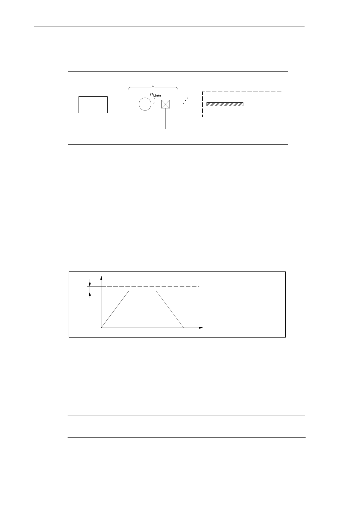
Velocities, Setpoint/Actual-Value Systems, Closed- Loop Control (G2)
3.3 Setpoint/actual-value system
3.3.4 Speed setpoint output
MD 32100: AX_MOTION_DIR
Controller
Fig. 3-5 Speed setpoint output
Traversing direction
MD 32100: AX_MOTION_DIR (traversing direction) can be used to revert the traversing direction of the axis (without effect on the control direction of the position control).
Maximum speed setpoint
The maximum speed setpoint is defined using MD 36210: CTRLOUT_LIMIT. The value as a
percentage refers to the speed (100 %) at which the axis velocity of MD 32000:
MAX_AX_VELO is reached. A value greater than 100 % contains the required control margin
for the position control of axes.
n
Motor
M
Load
gear
MD 31060: DRIVE_AX_RATIO_NUMERA[n]
MD 31050: DRIVE_AX_RATIO_DENOM[n]
n
Spindle
MD 31030: LEADSCREW_PITCH
Ball screw
only for linear axes
Number of motor rev’s
=
Number of load revolutions (spindle)
n
= speed setpoint
set
5- 25%
Max. speed setpoint
MD 36210: CTRLOUT_LIMIT
Speed at:
Max. axis velocity
MD 32000: MAX_AX_VELO
t [sec]
Fig. 3-6 Speed setpoint output
If values above the limit are specified, the value is limited to the value defined in MD 36210,
the axes are stopped, and an alarm is output. For detailed information, see Section “Axis monitoring functions”.
In the case of an analog spindle, the maximum output speed is limited by the maximum setpoint output voltage of 10 V. The value of MD 36210: CTRLOUT_LIMIT should not be above the
speed setpoint reached at this voltage (100 %).
Note
For special features regarding the control of a spindle, please refer to the Chapter “Spindle”.
3-62
SINUMERIK 802D, 802D base line
6FC5 697-2AA10-0BP2 (11.03) (DF)
Page 63
Velocities, Setpoint/Actual-Value Systems, Closed- Loop Control (G2)
3.3.5 Actual- value processing
Actual- value resolution
To create a position control loop that is connected correctly, it is necessary to convey the actual-value resolution to the control system.
Parameterize the following machine data for the main applications depending on the axis type
(linear axis, rotary axis/spindle, analog spindle) and depending on the type of actual value
acquisition (direct, indirect) to calculate the actual value resolution:
Machine Data Linear Axis Rotary Axis Spindle
MD 30200: NUM_ENCS
(number of encoders)
3.3 Setpoint/actual-value system
Encoder on
motor
1 1 1 1 0
Encoder on
motor
Encoder on
motor
Encoder on
machine
without
measuring
system
MD 30300: IS_ROT_AX
(rotary axis)
MD 31040: ENC_IS_DIRECT[0]
(encoder is installed directly on the machine)
MD 31020: ENC_RESOL[0]
(encoder increments per revolution)
MD 31030: LEADSCREW_PITCH
(leadscrew pitch)
MD 31080:
DRIVE_ENC_RATIO_NUMERA[n]
(measuring gear numerator)
MD 31070:
DRIVE_ENC_RATIO_DENOM[n]
(resolver gearbox denominator)
MD 31060:
DRIVE_AX_RATIO_NUMERA[n]
(load gear numerator)
MD 31050:
DRIVE_AX_RATIO_DENOM[n]
(load gear denominator)
- = not applicable to this combination
The index [n] of the machine data is coded as follows:
MD: DRIVE_AX_...[servo parameter set no.] : 0-5
0 1 1 1 1
0 0 0 1 1
incr./rev. incr./rev. incr./rev. incr./rev. -
mm/rev. - - - -
- - - load rev’s -
- - - encoder
motor rev’s motor rev’s motor rev’s see
ball screw
spindle
rev’s
load rev’s load rev’s see
rev’s
note *)
note *)
-
-
-
Note
*) These MD are not required for the encoder adaptation (path evaluation). For setpoint calculation,
however, they must be entered correctly! Otherwise, the desired loop gain factor will not be set.
Variants of actual- value sensing
The appropriate machine data for the individual variants of actual value sensing are decribed
in the following.
SINUMERIK 802D, 802D base line
6FC5 697-2AA10-0BP2 (11.03) (DF)
3-63
Page 64
Velocities, Setpoint/Actual-Value Systems, Closed- Loop Control (G2)
3.3 Setpoint/actual-value system
Linear axis with rotatory encoder installed on the motor
MD:
IS_ROT_AX = 0
n
Encoder
G
MD:
ENC_IS_DIRECT=0
M
Table
Ball screw
MD:
ENC_RESOL
n
Motor
Load
gear
n
Spindle
MD:
DRIVE_AX_RATIO_NUMERA
MD:
DRIVE_AX_RATIO_DENOM
Fig. 3-7 Linear axis with rotary encoder installed on the motor
Rotary axis with rotary encoder installed on the motor
MD:
ENC_IS_DIRECT=0
n
Encoder
M
Load
gear
MD:
ENC_RESOL
n
Motor
Fig. 3-8 Rotary axis with rotary encoder installed on the motor
MD:
IS_ROT_AX=1
n
Load
LG
DRIVE_AX_RATIO_NUMERA No. of motor rev’s
MD:
DRIVE_AX_RATIO_DENOM=No. of load rev’s
MD:
Spindle with rotary encoder installed on the machine
LEADSCREW_PITCH
No. of motor rev’s
=
No. of spindle rev’s
Rotary table
n
Load
Spindle chuck
MD:
IS_ROT_AX=1
Load
gear
MD:
ENC_IS_DIRECT=1
n
L
Encoder
Resolver
gear
GM
MD:
MD:
MD:
ENC_RESOL
DRIVE_ENC_RATIO_NUMERA
DRIVE_ENC_RATIO_DENOM=No. of load rev’s
No. of load rev’s
Fig. 3-9 Spindle with rotarory encoder installed on the the machine
Note:
MD 32110: ENC_FEEDBACK_POL (sign of actual value) can be used to change the sign of
the actual-value sensing and thus also the control direction of the position control.
3-64
SINUMERIK 802D, 802D base line
6FC5 697-2AA10-0BP2 (11.03) (DF)
Page 65

Velocities, Setpoint/Actual-Value Systems, Closed- Loop Control (G2)
3.4 Closed-loop control
General
The closed-loop control of an axis consists of the current and of the speed control loop of the
drive and of a higher-livel position-control loop in the NC.
The speed and current control are explained in:
References: Description of Functions “SIMODRIVE 611 UE”
3.4 Closed-loop control
MD 32400: AX_JERK_ENABLE
MD 32410: AX_JERK_TIME
Interpolator/
jerk limitation
MD 32620: FFW_MODE
MD 32630: FFW_ACTIVATION_MODE
MD 32610: VELO_FFW_WEIGHT
MD 32810: EQUIV_SPEEDCTRL_TIME
Fig. 3-10 Principle of the position control of an axis/spindle
Feedforward
control
For the description of the jerk limitation, see:
References: Section ”Acceleration”
For the description of feedforward control, backlash and backlash error compensation, see:
References: Section ”Compensations”
MD 32200: POSCTRL_GAIN
Closed-loop Speed
control
MD 32100: AX_MOTION_DIR
IS: Position encoder 1
MD 32110: ENC_FEEDBACK_POL
MD 32700: ENC_COMP_ENABLE
MD 32450: BACKLASH
setpoint
processing
Actual-value
value
processing
Servo gain factor
To ensure that there are only small contour deviations in continuous - path mode, a high servo
gain factor MD 32200: POSCTRL_GAIN[n] (position controller-loop gain) is required.
The index[n] of the machine data is coded as follows:
[control parameter set No.]: 0 - 5
If the loop gain factor is too high, however, overshot and (in some cases) inadmissible high
loads on the machine may be the consequence.
SINUMERIK 802D, 802D base line
6FC5 697-2AA10-0BP2 (11.03) (DF)
3-65
Page 66

Velocities, Setpoint/Actual-Value Systems, Closed- Loop Control (G2)
3.4 Closed-loop control
The maximum permissible servo gain depends on:
dimensioning and dynamic properties of the drive
(rise time, acceleration and brake properties)
quality of machine (elasticity, vibration dampening)
position-control clock
KV
Speed
Followingerror
[mmin]
;
[mm]
Parameter sets of the position controller
The position control can use up to 6 different parameter sets. These serve for
quick accomodation of the position controller to modified properties of the machine during
operation, e.g. when switching over the spindle gearbox.
accomodation of the dynamic properties of an axis to another axis, e.g. on tapping.
The following machine data can jointly be changed by parameter set switchover during opera-
tion.
MD 31050: DRIVE_AX_RATIO_DENOM[n] (load gear denominator)
MD 31060: DRIVE_AX_RATIO_NUMERA[n] (load gear numerator)
MD 32200: POSCTRL_GAIN[n] (servo gain factor)
MD 32810: EQUIV_SPEEDCTRL_TIME[n] (equivalent time constant of speed control loop for
MD 36200: AX_VELO_LIMIT[n] (threshold value for velocity monitoring)
The index [n] of the machine data is coded as follows:
[control parameter set No.]: 0-5
Unit of servo gain factor acc. to the VDI standard
feedforward control)
Parameter sets for spindle:
With the spindle, each gear stage is assigned its own parameter set. Depending on the IS
“Actual gear stage” (V380x2000.0 to .2), the appropriate parameter set is activated.
Note: For the machine data required to switchover the gear stage of the spindle, please refer
to the Chapter “Spindle”.
IS ”Actual Gear Stage“ Active Parameter Set
000 2 (Index=1)
001 2 (Index=1)
010 3 (Index=2)
011 4 (Index=3)
100 5 (Index=4)
101 6 (Index=5)
3-66
SINUMERIK 802D, 802D base line
6FC5 697-2AA10-0BP2 (11.03) (DF)
Page 67

Velocities, Setpoint/Actual-Value Systems, Closed- Loop Control (G2)
3.4 Closed-loop control
Parameter sets for axes
- For axes not involved in tapping or thread cutting, parameter set 1 (index=0) is activated in any case.
- For axes involved in tapping or thread cutting, the same parameter set number is activated as for the current gear stage of a spindle.
Note
For example, if a load gear is active for an axis, then this transmission ratio (numerator, denominator) must also be entered in all of the remaining sets of parameters used for threads, in
addition to the parameter set with the index =0.
The current parameter set is displayed in the operating area “Diagnosis” in the display ”Service of axis”.
SINUMERIK 802D, 802D base line
6FC5 697-2AA10-0BP2 (11.03) (DF)
3-67
Page 68

Velocities, Setpoint/Actual-Value Systems, Closed- Loop Control (G2)
3.5 Data description (MD, SD)
3.5 Data description (MD, SD)
3.5.1 General machine data
10200 ** INT_INCR_PER_MM
MD number Computational resolution for linear positions
Default: 1000 Min. input limit: 1.0 Max. input limit:
Change valid after Power On Protection level: 2/2 Unit: Data type: DOUBLE Valid from SW release:
Meaning: This MD is used to define the number of internal increments per millimiter.
The input accuracy of linear positions is limited to the computational resolution by rounding the
product of the programmed value with the computational resolution to an integer number.
To be able to trace the rounding easily, numbers raised to the power of 10 should be used for the
computational resolution.
Application example(s) In the case of high demands on the accuracy of linear axes, the computational resolution can be
increased to values greater than 1,000 incr./mm.
** This machine data is not available with the 802D base line.
10210 ** INT_INCR_PER_DEG
MD number Computational resolution for angular positions
Default: 1000 Min. input limit: 1.0 Max. input limit:
Change valid after Power On Protection level: 2/2 Unit: Data type: DOUBLE Valid from SW release:
Meaning: This MD is used to define the number of internal increments per degree.
The input accuracy of angular positions is limited to the computational resolution by rounding the
product of the programmed value with the computational resolution to an integer number.
To be able to trace the rounding easily, numbers raised to the power of 10 should be used for the
computational resolution.
Application example(s) For a high - resolution rotary axis, the computational resolution can be changed to < 1,000 incr./de-
grees.
***
***
** This machine data is not available with the 802D base line.
10240 SCALING_SYSTEM_IS_METRIC
MD number Metric scaling system
Default: 1 Min. input limit: 0 Max. input limit: 1
Change valid after Power On Protection level: 2/2 Unit: Data type: BOOLEAN Valid from SW release:
Meaning: The MD defines the scaling system used by the control system for the scaling of length-dependent
Application example(s) Start-up in the metric system and then conversion to the inch system
physical quantities for data I/O.
Internally, all data are stored in the basic units 1 mm, 1 degree and 1 sec.
When accessing from the part program, the operator panel or via external communication, the
following units are used for scaling:
SCALING_SYSTEM_IS_METRIC = 1: scaled in:
SCALING_SYSTEM_IS_METRIC = 0: scaled in:
The selection of the scaling system also defines the interpretation of the F value programmed for
linear axes:
G94 mm/min inch/min
G95 mm/rev. inch/rev.
After the machine data have been modified, the control system must be rebooted; otherwise, the
machine data with physical units will not be scaled correctly.
Observe the following procedure:
MD change by manual input
MD change is carried out using a machine data file
If the machine data are modified, the alarm 4070 ”Scaled machine data changed” is output.
mm, mm/min, m/s2, m/s
inch, inch/min, inch/s2, inch/s
metric inch
Reboot the control system and then enter the appropriate machine data with their
physical units
Reboot the control system and then reload the machine data file so that the physical
units come into effect.
3,
mm/rev.
3,
inch/rev.
3-68
SINUMERIK 802D, 802D base line
6FC5 697-2AA10-0BP2 (11.03) (DF)
Page 69

Velocities, Setpoint/Actual-Value Systems, Closed- Loop Control (G2)
)
+ Double-axis power section (DP addr.13: Drive A = drive no. 3
drive B = drive no. 4)
3.5 Data description (MD, SD)
11240 PROFIBUS_SDB_NUMBER
MD number SDB1000 number
Default: 0 Min. input limit: 0 Max. input limit: 6
Change valid after Power On Protection level: 2/2 Unit: Data type: BYTE Valid from SW release: 2
Meaning: Number of the system data block (SDB1000) used for configuring the Profibus I/Os. With
SINUMERIK 802D, the following possibilities are offered:
0: I/O module: 1st PP (DP addr.9 ), 2nd PP (DP addr.8) = digital inputs/outputs
Drives: none (axes in simulation)
1, 2: reserved
3: I/O module: 1st PP (DP addr.9 ), 2nd PP (DP addr.8) = digital inputs/outputs
Drives:
Double-axis power section (DP addr.12: Drive A = drive no. 1, drive B = drive no. 2)
+ Single-axis power section (DP addr.10 = drive no. 5)
+ Single-axis power section (DP addr.11 = drive no. 6)
4: I/O module: 1st PP (DP addr.9 ), 2nd PP (DP addr.8) = digital inputs/outputs
Drives:
Double-axis power section (DP addr.12: Drive A = drive no. 1, Antrieb B = drive no. 2)
+ Double-axis power section (DP addr.13: Drive A = drive no. 3, Antrieb B = drive no. 4)
+ Single-axis power section (DP addr.10 = drive no. 5)
5: I/O module: 1st PP (DP addr.9 ), 2nd PP (DP addr.8) = digital inputs/outputs
Drives:
Single-axis power section (DP addr.20 = drive no. 1)
+ Single-axis power section (DP addr.21 = drive no. 2)
+ Double-axis power section (DP addr.13: Drive A = drive no. 3, drive B = drive no. 4
+ Single-axis power section (DP addr.10 = drive no. 5)
6: I/O module: 1st PP (DP addr.9 ), 2nd PP (DP addr.8) = digital inputs/outputs
Drives:
Einachs-Leistungsteil (DP-Adr.20 = drive no. 1)
+ Single-axis power section (DP addr.21 = drive no. 2)
+ Single-axis power section (DP addr.22 = drive no. 3)
+ Single-axis power section (DP addr.10 = drive no. 5)
Note:
The assignment of a drive to the relevant machine axis is provided via the axis-specific machine
data CTRLOUT_MODULE_NR = ENC_MODULE_NR = drive number.
,
SINUMERIK 802D, 802D base line
6FC5 697-2AA10-0BP2 (11.03) (DF)
3-69
Page 70

Velocities, Setpoint/Actual-Value Systems, Closed- Loop Control (G2)
Index [n] of the machine data is coded as follows: [drive index]:
3.5 Data description (MD, SD)
13060 DRIVE_TELEGRAM_TYPE[n]
MD number Default message type for drives at Profibus DP
Default:
(102, 102, 102, 102, 102)
Change valid after Power On Protection level: 2/2 Unit: Data type: DWORD Valid from SW release:
Meaning: Specify the message type for each drive at Profibus DP:
0: for additional analog spindle control on the drive
102: SIMODRIVE 611UE - digital axis/spindle
104: SIMODRIVE 611UE - spindle with direct measuring system
Index [n] of the machine data is coded as follows: [drive index]:
n=0: drive 1
n=1: drive 2, etc.
Min. input limit: 0 Max. input limit: ***
3.5.2 Channel -specific machine data
20150 GCODE_RESET_VALUES[n]
MD number Erase position of the G groups [G group no.]: 0...59
Default: see below Min. input limit: 0 Max. input limit: 14
Change valid after RESET Protection level: 1/1 Unit: Data type: BYTE Valid from SW release:
Meaning: Definition of the G codes that become active during start-up and reset or at the end of the part
Further references
program and when starting the part program.
As a default value, the index of the G codes must be specified in the appropriate groups.
Designation Group Standard Value
GCODE_RESET_VALUES[0] 1 2 (G01)
GCODE_RESET_VALUES[1] 2 0 (inactive)
GCODE_RESET_VALUES[2] 3 0 (inactive)
GCODE_RESET_VALUES[3] 4 1 (START FIFO)
GCODE_RESET_VALUES[4] 5 0 (inactive)
GCODE_RESET_VALUES[5] 6 1 (G17) for milling
GCODE_RESET_VALUES[6] 7 1 (G40)
GCODE_RESET_VALUES[7] 8 1 (G500)
GCODE_RESET_VALUES[8] 9 0 (inactive)
GCODE_RESET_VALUES[9] 10 1 (G60)
GCODE_RESET_VALUES[10] 11 0 (inactive)
GCODE_RESET_VALUES[11] 12 1 (G601)
GCODE_RESET_VALUES[12] 13 2 (G71)
GCODE_RESET_VALUES[13] 14 1 (G90)
GCODE_RESET_VALUES[14] 15 2 (G94)
GCODE_RESET_VALUES[15] 16 1 (CFC)
...
For a list of the G groups and the functions assigned to them, please refere to:
References: “Operation and Programming”
3-70
SINUMERIK 802D, 802D base line
6FC5 697-2AA10-0BP2 (11.03) (DF)
Page 71

Velocities, Setpoint/Actual-Value Systems, Closed- Loop Control (G2)
3.5 Data description (MD, SD)
3.5.3 Axis- specific machine data
30110 CTRLOUT_MODULE_NR[n]
MD number Setpoint: Drive number/module number
Default: 1 Min. input limit: 1 Max. input limit: 9
Change valid after Power On Protection level: 2/2 Unit: Data type: BYTE Valid from SW release:
Meaning: Enter the drive number for a standard axis.
For an analog spindle:
Enter the transferring drive number used to address the output for the analog spindle.
Index [n] of the machine data is coded as follows: [Setpoint branch]: 0
30120 CTRLOUT_NR[n]
MD number Setpoint: Output on the module
Default: 1 Min. input limit: 1 Max. input limit: 2
Change valid after Power On Protection level: 2/2 Unit: Data type: BYTE Valid from SW release:
Meaning: Number of output on a module used to address the setpoint output.
Index [n] of the machine data is coded as follows: [setpoint branch]: 0
30130 CTRLOUT_TYPE[n]
MD number Setpoint output type
Default: 0 Min. input limit: 0 Max. input limit: 1
Change valid after Power On Protection level: 2/2 Unit: Data type: BYTE Valid from SW release:
Meaning: In this MD, the type of the speed setpoint output is entered:
Application example(s) Simulation: Machine functions can also be simulated without a drive connected.
30200 NUM_ENCS
MD number Number of encoders
Default: 1 Min. input limit: 0 Max. input limit: 1
Change valid after Power On Protection level: 2/2 Unit: Data type: BYTE Valid from SW release:
Meaning: 1: Spindle/axis with direct measuring system (integrated in the motor or direct)
30220 ENC_MODULE_NR[n]
MD number Actual value: Drive number/measuring circuit number
Default: 1 Min. input limit: 1 Max. input limit: 9
Change valid after Power On Protection level: 2/7 Unit: Data type: BYTE Valid from SW release:
Meaning: Enter the drive number for a standard axis/spindle.
0: Simulation (no hardware required)
1: Setpoint output active
Index [n] of the machine data is coded as follows: [setpoint branch]: 0
0: without measuring system (possible with spindle)
For an analog spindle:
Enter the transferring drive number used to address the output for the analog spindle.
Index [n] of the machine data is coded as follows: [encoder no.]: 0
SINUMERIK 802D, 802D base line
6FC5 697-2AA10-0BP2 (11.03) (DF)
3-71
Page 72

Velocities, Setpoint/Actual-Value Systems, Closed- Loop Control (G2)
3.5 Data description (MD, SD)
30230 ENC_INPUT_NR[n]
MD number Actual value: Input number on module/measuring circuit card
Default: 0 Min. input limit: 0 Max. input limit: 5
Change valid after Power On Protection level: 2/2 Unit: Data type: BYTE Valid from SW release:
Meaning: Number of the input on a module, which is used to address the encoder.
The index[n] of the machine data is coded as follows: [encoder no.]: 0
Application example(s) Simulation:
30240 ENC_TYPE[n]
MD number Actual value: Encoder type
Default: 0 Min. input limit: 0 Max. input limit: 4
Change valid after Power On Protection level: 2/2 Unit: Data type: BYTE Valid from SW release:
Meaning: In this MD, the type of the encoder used is entered:
Application example(s) Simulation:
Machine functions can be simulated even without a measuring system connected.
0: Simulation
1: Signal generator (1VSS, sin, cos)
4: Absolute encoder with EnDat interface
2, 3, 5: reserved
Index [n] of the machine data is coded as follows: [encoder No.]: 0
Machine functions can also be simulated without measuring system connected.
30350 SIMU_AX_VDI_OUTPUT
MD number Output of axis signals with simulation axes
Default: 0 Min. input limit: 0 Max. input limit: 1
Change valid after Power On Protection level: 2/2 Unit: Data type: BOOLEAN Valid from SW release:
Meaning: This machine data is used to define whether during the simulation of an axis axis-specific interface
MD inapplicable ...... MD 30130: CTRLOUT_TYPE (setpoint output type) = 1
Application example(s) MD: SIMU_AX_VDI_OUTPUT = 0
31000 ENC_IS_LINEAR
MD number Direct measuring system (linear scale)
Default: 0 Min. input limit: *** Max. input limit: ***
Change valid after Power On Protection level: 2/2 Unit:
Data type: BOOLEAN Valid from SW release: 1.1
Meaning: Value 1: Encoder is a linear scale
Further references
31010 ENC_GRID_POINT_DIST
MD number Scale division with linear scales
Default: 0.01 Min. input limit: 0.0 Max. input limit: ***
Change valid after Power On Protection level: 2/2 Unit: mm
Data type: DOUBLE Valid from SW release: 1.1
Meaning: Distance of increments with linear encoders
Further references
signals are output to the PLC.
1: The axis-specific IS (interface signals) of a simulated axis are output to the PLC.
It is thus possible to test the PLC user program without the need to connect drives.
0: The axis-specific interface signals of a simulated axis are not output to the PLC.
All axis-specific interface signals are set to “0”.
This prevents, e.g. that during the simulation of an axis the brake is released.
3-72
SINUMERIK 802D, 802D base line
6FC5 697-2AA10-0BP2 (11.03) (DF)
Page 73

Velocities, Setpoint/Actual-Value Systems, Closed- Loop Control (G2)
3.5 Data description (MD, SD)
31020 ENC_RESOL[n]
MD number Increments per revolution
Default: 2048 Min. input limit: 0 Max. input limit: ***
Change valid after Power On Protection level: 2/2 Unit: Data type: DWORD Valid from SW release:
Meaning: In this MD, the increments per encoder revolution are entered.
31030 LEADSCREW_PITCH
MD number Leadscrew pitch
Default: 10.0 Min. input limit: 0.0 Max. input limit: ***
Change valid after Power On Protection level: 2/2 Unit: mm/rev.
Data type: DOUBLE Valid from SW release:
Meaning: In this MD, the leadscrew pitch is entered.
31040 ENC_IS_DIRECT[n]
MD number The encoder is directly mounted on the machine.
Default: 0 Min. input limit: 0 Max. input limit: 1
Change valid after Power On Protection level: 2/2 Unit: Data type: BOOLEAN Valid from SW release:
Meaning: 1: Encoder for actual position sensing is mounted directly on the machine.
Special cases, errors, ...... A wrong entry may result in wrong encoder resolution, since, e.g. the wrong gear transmission
The index [n] of the machine data is coded as follows: [encoder No.]: 0
0: Encoder for actual position sensing is mounted on the motor.
Index [n] of the machine data is coded as follows: [encoder No.]: 0
ratios are calculated.
31050 DRIVE_AX_RATIO_DENOM[n]
MD number Load gear denominator
Default: 1 Min. input limit: 1 Max. input limit: 2 147 000 000
Change valid after Power On Protection level: 2/2 Unit: Data type: DWORD Valid from SW release:
Meaning: In this MD, the denominator of the load gear must be entered.
Further references
31060 DRIVE_AX_RATIO_NUMERA[n]
MD number Load gear numerator
Default: 1 Min. input limit: - 2 147 000 000 Max. input limit: 2 147 000 000
Change valid after Power On Protection level: 2/2 Unit: Data type: DWORD Valid from SW release:
Meaning: In this MD, the numerator of the load gear is entered.
31070 DRIVE_ENC_RATIO_DENOM[n]
MD number Resolver gearbox denominator
Default: 1 Min. input limit: 1 Max. input limit: 21 47 000 000
Change valid after Power On Protection level: 2/2 Unit: Data type: DWORD Valid from SW release:
Meaning: In this MD, the name of the resolver gearbox is entered.
31080 DRIVE_ENC_RATIO_NUMERA[n]
MD number Resolver gearbox numerator
Default: 1 Min. input limit: 1 Max. input limit: 2 147 000 000
Change valid after Power On Protection level: 2/2 Unit: Data type: DWORD Valid from SW release:
Meaning: In this MD, the numerator of the resolver gearbox is entered.
Index [n] of the machine data is coded as follows: [control parameter set No.]: 0-5
Index [n] of the machine data is coded as follows: [control parameter set No.]: 0-5
Index [n] of the machine data is coded as follows: [encoder No.]: 0
The index [n] of the machine data is coded as follows: [encoder No.]: 0
SINUMERIK 802D, 802D base line
6FC5 697-2AA10-0BP2 (11.03) (DF)
3-73
Page 74

Velocities, Setpoint/Actual-Value Systems, Closed- Loop Control (G2)
3.5 Data description (MD, SD)
32000 MAX_AX_VELO
MD number Maximum axis velocity
Default: 10 000 mm/min,
27.77 rpm
Change valid after NEW_CONF Protection level: 2/7 Unit: mm/min,
Data type: DOUBLE Valid from SW release:
Meaning: In this MD, enter the limit velocity up to which the axis can accelerate (rapid traverse limitation).
If rapid traverse G0 is programmed, this speed is used for traversing. Depending on
MD: IS_ROT_AX, enter the maximum linear ond/or rotary axis speed in the MD.
The max. permissible axis velocity depends on the machine and axis dynamics and the limit frequency of actual-value sensing.
32100 AX_MOTION_DIR
MD number Traversing direction
Default: 1 Min. input limit: - 1 Max. input limit: 1
Change valid after Power On Protection level: 2/2 Unit: Data type: BYTE Valid from SW release:
Meaning: This MD can be used to revert the direction of rotation of the machine axis. The control direction,
however, is not reverted, i.e. the closed -loop control remains stable.
0 or 1: no direction reversal
-1: direction reversal
Min. input limit: 0.0 Max. input limit: ***
rpm
32110 ENC_FEEDBACK_POL[n]
MD number Sign of actual value (control direction)
Default: 1 Min. input limit: - 1 Max. input limit: 1
Change valid after Power On Protection level: 2/2 Unit: Data type:BYTE Valid from SW release:
Meaning: In this MD, the direction of evaluation of the encoder signals is entered.
Special cases, errors, ...... If a wrong control direction is entered, the axis may run away.
0 or 1: no direction reversal
-1: direction reversal
In the case of direction reversal, the control direction is also reverted if the encoder is used for the
position control.
Index [n] of the machine data is coded as follows: [encoder No.]: 0
Depending on the setting of the corresponding limit values, one of the following alarms may occur:
Alarm 25040 ”Zero-speed control“
Alarm 25050 ”Contour monitoring“
Alarm 25060 ”Speed setpoint limitation”
The corresponding limit values are described in:
References: Section ”Axis Monitoring Functions”
If there is an uncontrolled, sudden setpoint change when connecting a drive, a wrong control direction may have been set.
3-74
SINUMERIK 802D, 802D base line
6FC5 697-2AA10-0BP2 (11.03) (DF)
Page 75

Velocities, Setpoint/Actual-Value Systems, Closed- Loop Control (G2)
3.5 Data description (MD, SD)
32200 POSCTRL_GAIN[n]
MD number Servo gain factor
Default: 1.0 Min. input limit: 0.0 Max. input limit: 2000
Change valid after NEW_CONF Protection level: 2/7 Unit: (m/min)/mm
Data type: DOUBLE Valid from SW release:
Meaning: Position controller gain, so-called servo gain factor.
36210 CTRLOUT_LIMIT[n]
MD number Max. speed setpoint
Default: 110.0 Min. input limit: 0.0 Max. input limit: 200
Change valid after NEW_CONF Protection level: 2/7 Unit: %
Data type: DOUBLE Valid from SW release:
Meaning: This MD is used to define the maximum speed setpoint value in per cent.
The input/output unit for the user is [ (m/min)/mm].
i.e. POSCTRL_GAIN[n] = 1 corresponds to 1 mm following error at V = 1 m/min.
If ”0” is entered, the position controller is disconnected.
When entering the servo gain factor, take into account that the gain factor of the entire position
control loop is also dependent on other parameters of the controlled system. A distinction must
therefore be made between a ”desired servo gain factor” (MD: POSCTRL_GAIN) and a ”real servo
gain factor“ (resulting on the machine). Only if all parameters of the control loop are matched another to one correctly, these servo gain factors are identical.
Note:
The axes which interpolate another to one and have to carry out a machining process, must have
the same gain (i.e. the same following error at the same velocity).
The real servo gain factor can be checked by means of the following error in the service displays.
Index [n] of the machine data is coded as follows: [control parameter set No.]: 0-5
This specification refers to the speed (100 %) at which the velocity defined in MD 32000:
MAX_AX_VELO is reached. A value greater than 100 % contains the required control margin with
digital drives.
If values above the limit are specified, the value is limited to the MD value, the axes are stopped
and an alarm is generated.
With an analog spindle, the maximum output speed is limited by the maximum setpoint output
voltage of 10 V. The value in this MD should not be above the speed setpoint reached at this voltage (100 %).
Index[n] of the machine data is coded as follows: [setpoint branch]: 0
Further references see Section “Axis monitoring functions”
37600 ** PROFIBUS_ACTVAL_LEAD_TIME
MD number Actual-value sensing time (Profibus Ti)
Default: 0.000125 Min. input limit: 0.0 Max. input limit: 0.032
Change valid after Power On Protection level: 2/7 Unit: s
Data type: DOUBLE Valid from SW release: 1.1
Meaning: Data for setting the actual-value acceptance time (Ti) of the encoder at Profibus (Ti).
Further references
Note:
The real Ti value is read either directly from the Profibus configuration or from the drive (if possible). In this case, the value of the machine data is set to the read value and only serves for displaying.
** This machine data is not available with the 802D base line.
SINUMERIK 802D, 802D base line
6FC5 697-2AA10-0BP2 (11.03) (DF)
3-75
Page 76

Velocities, Setpoint/Actual-Value Systems, Closed- Loop Control (G2)
3.6 Signal descriptions
3.6 Signal descriptions
V2700 0001.7 System inch unit
Interface signal Signal(s) to NC (PLC - --> NC)
Edge evaluation: no Signal(s) updated: cyclically Signal(s) valid from SW release:
Signal state 1 The NC uses the inch scaling system.
Signal state 0 The NC uses the metric scaling system.
3-76
SINUMERIK 802D, 802D base line
6FC5 697-2AA10-0BP2 (11.03) (DF)
Page 77

Velocities, Setpoint/Actual-Value Systems, Closed- Loop Control (G2)
3.7 Data fields, data lists
3.7 Data fields, data lists
3.7.1 Interface signals
Number .Bit Name Ref.
General
V27000001 .7 System inch unit
Axis-specific
V380x 2000 .0 to .2
Actual gear stage of spindle
3.7.2 Machine data
Number Identifier Name Ref.
Operator- panel specific
203 DISPLAY_RESOLUTION Display resolution Chapter 19
204 DISPLAY_RESOLUTION_INCH Display resolution for INCH scaling system Chapter 19
205 DISPLAY_RESOLUTION_SPINDLE Display resolution for spindle Chapter 19
General
10000 AXCONF_MACHAX_NAME_TAB[n] Machine axis name Chapter 19
10200** INT_INCR_PER_MM Computational resolution for linear positions
10210** INT_INCR_PER_DEG Computational resolution for angle positions
10240 SCALING_SYSTEM_IS_METRIC Metric scaling system
11240 PROFIBUS_SDB_NUMBER SDB1000 number (Profibus DP)
13060 DRIVE_TELEGRAM_TYPE[n] Default message type for drives at Profibus DP
Channel-specific
20150 GCODE_RESET_VALUES[n] Reset position of G groups
Axis- specific
30110 CTRLOUT_MODULE_NR[n] Setpoint assignment: Drive number/module number
30120 CTRLOUT_NR[0] Setpoint: Output on module
30130 CTRLOUT_TYPE[n] Setpoint output type
30134 IS_UNIPOLAR_OUTPUT Setpoint output is unipolar (analog spindle) S1
30200 NUM_ENCS Number of encoders =1 (spindle without encoder
30220 ENC_MODULE_NR[n] Actual-value: Drive module no./measuring circuit no.
30230 ENC_INPUT_NR[0] Actual value: Input number on module/measuring cir-
30240 ENC_TYPE[n] Actual-value sensing mode (actual position)
30300 IS_ROT_AX Rotary axis R2
30350 SIMU_AX_VDI_OUTPUT Output of axis signals with simulation axes
31000 ENC_IS_LINEAR Direct measuring system (linear scale)
31010 ENC_GRID_POINT_DIST Scaling division with linear scales
31020 ENC_RESOL[n] Increments per revolution
31030 LEADSCREW_PITCH Leadscrew pitch
31040 ENC_IS_DIRECT[n] Encoder is mounted directly on the machine
(analog spindle)
value =0)
cuit card
S1
SINUMERIK 802D, 802D base line
6FC5 697-2AA10-0BP2 (11.03) (DF)
3-77
Page 78

Velocities, Setpoint/Actual-Value Systems, Closed- Loop Control (G2)
3.7 Data fields, data lists
Number Ref.NameIdentifier
31050 * DRIVE_AX_RATIO_DENOM[n] Load gear denominator
31060 * DRIVE_AX_RATIO_NUMERA[n] Load gear numerator
31070 DRIVE_ENC_RATIO_DENOM[n] Resolver gearbox denominator
31080 DRIVE_ENC_RATIO_NUMERA[n] Resolver gearbox numerator
32000 MAX_AX_VELO Maximum axis velocity
32100 AX_MOTION_DIR Traversing direction
32110 ENC_FEEDBACK_POL[n] Sign of actual value (control direction)
32200 * POSCTRL_GAIN[n] Servo gain factor
32450 BACKLASH[n] Backlash K3
32700 ENC_COMP_ENABLE[n] Interpolatory compensation K3
32810 * EQUIV_SPEEDCTRL_TIME[n] Equivalent time constant of speed control loop for
feedforward control
33630 FFW_ACTIVATION_MODE Activate feedforward control from program K3
35100 SPIND_VELO_LIMIT Maximum spindle speed S1
36200 * AX_VELO_LIMIT[n] Threshold value for velocity monitoring A3
36210 CTRLOUT_LIMIT[n] Max. speed setpoint
37600** PROFIBUS_ACTVAL_LEAD_TIME Actual-value sensing time (Profibus Ti)
The machine date marked with an * (asterisk) are contained in a parameter set of the position controller.
** This machine data is not available with the 802D base line.
K3
3-78
SINUMERIK 802D, 802D base line
6FC5 697-2AA10-0BP2 (11.03) (DF)
Page 79

Acceleration (B2)
4.1 Acceleration profiles
Sudden acceleration
In case of the v/t linear velocity control of an axis, which is usually used, the motion is controlled such that the acceleration changes suddenly over the time. With this discontinuous, sudden acceleration, jerk-free starting and deceleration of the axes is not possible, but a timeoptimized velocity/time profile can be realized.
Jerk-limited acceleration
The jerk is the change of the acceleration over the time. With jerk-limited acceleration, the
maximum acceleration is specified not suddenly, but along a ramp. Due to the smoother acceleration characteristic, the traversing time increases towards a sudden acceleration whereas
the path, velocity and acceleration remain the same. In some cases, this loss in time can be
compensated by setting a higher settable axis acceleration.
This, however, has the following advantages:
4
Saving of the machine mechanics
Reduction of the excitation of high-frequency vibrations of the machine, which can badly
be controlled.
SINUMERIK 802D, 802D base line
6FC5 697-2AA10-0BP2 (11.03) (DF)
4-79
Page 80

Acceleration (B2)
4.2 Jerk limitation on interpolator level
4.2 Jerk limitation on interpolator level
Note
This function is not available with the 802D base line.
Selection and deselection of jerk-limited acceleration
MD 32431: MAX_AX_JERK (maximum axial jerk on path traversing) can be used to limit the
acceleration change for each machine axis separately. It is active for the axes that are interpolated by the path provided that SOFT is active. The jerk-limited acceleration is exclusively
carried out on the interpolator level.
The jerk-limited acceleration is enabled by:
programming SOFT in the part program. SOFT is modally active and deselects the sudden
acceleration profile (BRISK). If SOFT is programmed with path axes in one and the same
block, the previous block is completed with exact stop.
Active range
The jerk-limited acceleration (SOFT) is disabled by:
programming BRISK in the part program. BRISK is modally active. If path axes are programmed with BRISK in one and the same block, the previous block is completed with
exact stop. The sudden acceleration profile of the v/t linear velocity control is enabled
using BRISK.
The path-related jerk limitation is available for the interpolating path axes in the operating modes AUTO and MDA. The acceleration profiles SOFT and BRISK can be used together with
the traversing mode “Exact stop” G09, G60, continuous-path mode G64 and LookAhead. The
profiles are also active with the function “Dry Run Feed”. Alarms that trigger off a rapid stop
will disable both acceleration profiles.
For more detailed information on the behavior of velocity, acceleration, jerk when traversing in
the continuous-path mode and, in particular, at block transitions, please refer to:
References: Section ”Continuous Path Mode, Exact Stop and Look Ahead”
Note: It is recommended to set the MD 32431: MAX_AX_JERK and
MD 32432: PATH_TRANS_JERK_LIM (maximum axis-specific jerk with path movement at
the block transition) to the same values for the appropriate axis.
4-80
SINUMERIK 802D, 802D base line
6FC5 697-2AA10-0BP2 (11.03) (DF)
Page 81

4.3 Jerk limitation in JOG mode
Note
This function is not available with the 802D base line.
The jerk limitation is active for axes in JOG mode on
manual traversing
handwheel traversing
repositioning.
The jerk limitation is not active
during reference point approach.
for alarms that cause rapid stop.
The jerk limitation can be specified axis-specifically. The acceleration behavior corresponds
to the acceleration profile SOFT of the path-related jerk limitation. This limitation cannot be
deselected for the axes in the individual operating modes.
Acceleration (B2)
4.3 Jerk limitation in JOG mode
Which of the desired axes will be provided with a jerk limitation, can be set in MD 32420:
JOG_AND_POS_JERK_ENABLE. The permissible axis-specific maximum jerk is stored in
MD 32430: JOG_AND_POS_MAX_JERK.
SINUMERIK 802D, 802D base line
6FC5 697-2AA10-0BP2 (11.03) (DF)
4-81
Page 82

Acceleration (B2)
4.4 Percentage acceleration correction, ACC
4.4 Percentage acceleration correction, ACC
Function
Some program sections may require to programmably modify the axis or spindle acceleration
defined in machine data. This programmable acceleration is a percentage acceleration correction.
The program command: ACC[channel axis name] = percentage value
can be used to program a percentage value > 0% and 200% for each axis (e.g.: X) or
spindle (S1). In this case, the axis interpolation is carried out on the basis of this proportional
acceleration. The acceleration stored in the axis-specific MD 32300: MAX_AX_ACCEL constitutes the reference for an axis (100%). For the spindle, this reference (100%) depends on
the active spindle mode and the gear stage (n = 1 ... 5)
MD 35200: GEAR_STEP_SPEEDCTRL_ACCEL[n] in control mode or
MD 35210: GEAR_STEP_POSCTRL_ACCEL[n] in positioning mode.
References: Chapter ”Spindle”
Example: N10 ACC[X]=80 ; 80% of the acceleration for the X axis
Activation
Error states
References: ”Operation and Programming”
The limitation is active in all interpolation modes of AUTOMATIC and MDA modes. The limitation is not active in JOG mode and during reference point approach.
The value assignment ACC[...] = 100 disables the correction (100% of the MD values); the
same applies to RESET and end of program.
The programmed value is also active during dry run feed.
The limitation of the acceleration is inactive in error states that lead to a rapid stop with open
position control loop (since the axis is stopped along a braking ramp of the speed setpoint
value).
Note: A value programmed greater than 100% can only be executed if the drives have the
appropriate reserves - otherwise, alarm messages are output.
4-82
SINUMERIK 802D, 802D base line
6FC5 697-2AA10-0BP2 (11.03) (DF)
Page 83

Acceleration (B2)
4.5 Data descriptions (MD, SD)
4.5 Data descriptions (MD, SD)
32300 MAX_AX_ACCEL
MD number Axis acceleration
Default: 1.0 m/s
Change valid after NEW_CONF Protection level: 2/7 Unit: m/s2, rev/s
Data type: DOUBLE Valid from SW release:
Meaning: The acceleration specifies a velocity change of the axis over a certain time. Different axes need
MD inapplicable to ...... error states resulting in rapid stop
32420 JOG_AND_POS_JERK_ENABLE
MD number Enable axis-specific jerk limitation
Default: 0 Min. input limit: 0 Max. input limit: 1
Change valid after RESET Protection level: 2/2 Unit: Data type: BOOLEAN Valid from SW release:
Meaning: Enables the function of axis-specific jerk limitation for the modes JOG, REF and the positioning
Related to .... MD 32430: JOG_AND_POS_MAX_JERK (axis- specific jerk)
2
2.77 rev/s
2
not absolutely necessary have the same acceleration. The lowest acceleration value will be used
for interpolating axes.
For rotary axes, the entered value corresponds to the angular acceleration.
The machine manufacturer must find out for which permanent brake mode and which permanent
acceleration is suited for the machine. This value must then be entered in this machine data.
The acceleration value is active for each acceleration/deceleration process.
axis mode.
Min. input limit: 0.0 Max. input limit: ***
2
32430 JOG_AND_POS_MAX_JERK
MD number Axis-specific jerk
Default: 1000.00 m/s3,
2777.77 rev./s
Change valid after RESET Protection level: 2/2
Data type: DOUBLE Valid from SW release:
Meaning: The jerk limit value limits the change in axis acceleration in JOG mode.
MD inapplicable to ...... path interpolation and error states resulting in rapid stop
Related to ...... MD 32420: JOG_AND_POS_JERK_ENABLE (enable axis - specific jerk limitation)
32431** MAX_AX_JERK
MD number Maximum axis-specific jerk when traversing along the contour
Default: 1000.00 m/s3,
2777.77 rev./s
Change valid after NEW_CONF Protection level: 3/3
Data type: DOUBLE Valid from SW release:
Meaning: This maximum axis-specific jerk is active with path movements.
Related to ... MD 32432: PATH_TRANS_JERK_LIM is active at block transition.
3
3
Path movements are possible in AUTO and MDA modes..
It is recommended to set both MD to the same value.
Min. input limit: 10
Min. input limit: 10
-9
-9
Max. input limit: ***
Unit: m/s3, rev./s
Max. input limit: ***
Unit: m/s3, rev./s
** This machine data is not available with the 802D base line.
3
3
SINUMERIK 802D, 802D base line
6FC5 697-2AA10-0BP2 (11.03) (DF)
4-83
Page 84

Acceleration (B2)
4.6 Data fields, lists
4.6 Data fields, lists
Number Identifier Name Ref.
Axis- specific machine data
32300 MAX_AX_ACCEL Axis acceleration
32420 JOG_AND_POS_JERK_ENABLE Enable axis- specific jerk limitation
32430 JOG_AND_POS_MAX_JERK Axial jerk
32431 MAX_AX_JERK Maximum axis-specific jerk for path movement
32432 PATH_TRANS_JERK_LIM Maximum axis-specific jerk for path movement at block
transition
B1
4-84
SINUMERIK 802D, 802D base line
6FC5 697-2AA10-0BP2 (11.03) (DF)
Page 85

Spindle (S1)
5.1 Brief description
Spindle application
Depending on the machine type, the following functions are possible for an NC- controlled
spindle:
Definition of a direction of rotation of the spindle (M3, M4)
Definition of a spindle speed (S)
Spindle stop, without orientation (M5)
Spindle positioning (SPOS=)
(position-controlled spindle required)
Gear step switchover (M40 to M45)
Thread cutting/tapping (G33, G331, G332, G63)
Revolutional feed (G95)
5
Constant cutting speed (G96)
Programmable spindle speed limitations (G25, G26, LIMS=)
Position encoder mounted on the spindle or on the spindle motor
Spindle monitoring for min. and max. speed
Dwell time in spindle revolutions (G4 S)
Instead of the controlled spindle, a “switched” spindle can be used. In this case, the spindle
speed (S) is not specified from the program, but, e.g. by manual operation (gearbox) on the
machine. It is thus also not possible to program any speed limitations. The following is possible via the program:
Definition of a direction of rotation of the spindle (M3, M4)
Spindle stop, without orientation (M5)
Tapping (G63)
If the spindle is equipped with a position encoder, in addition to the above mentioned functions, the functions listed below are possible:
Thread cutting/tapping (G33)
Revolutional feed (G95)
For a switched spindle, the setpoint output for the spindle via MD 30130: CTRLOUT_TYPE =0
must be suppressed.
SINUMERIK 802D, 802D base line
6FC5 697-2AA10-0BP2 (11.03) (DF)
5-85
Page 86

Spindle (S1)
5.2 Spindle modes
Defining the spindle
A machine axis is declared a spindle by setting the following machine data:
MD 30300: IS_ROT_AX, MD 30310: ROT_IS_MODULO, MD 30320: DISPLAY_IS_MODULO
and MD 35000: SPIND_ASSIGN_TO_MACHAX. The spindle mode is signaled by the IS
“Spindle/no axis“ (V390x 0000.0).
5.2 Spindle modes
Spindle modes
The spindle can be operated in the following modes:
Control mode see Section 5.2.1
Oscillation mode see Section 5.2.2.
Positioning mode see Section 5.2.3
Tapping without compensating chuck also refer to Section“Feed” (Thread Interpola-
tion) and
References: ”Operation and Programming“
Changing the spindle mode
Change
gear stage
Fig. 5-1 Changing between the spindle modes
Control mode - - -> oscillation mode
The spindle changes to oscillation mode if a new gear stage has been specified using the
automatic gear stage selection (M40) in conjunction with a new S value or by M41 to M45.
The spindle will only change to oscillation mode if the new gear stage is other than the current actual gear stage.
Oscillation m.
Gear stage
changed
SPOS
Control mode Positioning mode
M3, M4, M5,
M41-45
Rigid tapping
(without compen-
sating chuck)
SPOS
G331
G332
5-86
SINUMERIK 802D, 802D base line
6FC5 697-2AA10-0BP2 (11.03) (DF)
Page 87

Spindle (S1)
5.2 Spindle modes
Oscillation mode - - -> control mode
If the new gear stage has been selected, the IS “Oscillation mode” (V390x2002.6) is reset,
and the IS “Gear switched over” (V380x2000.3) will cause the spindle to change to control
mode. The spindle speed last programmed (S value) is active again.
Control mode - --> positioning mode
If the spindle is to be stopped from rotation (M3 or M4) with orientation or if the spindle is
to be re-oriented from the standstill (M5), switchover to positioning mode is carried out
using SPOS.
Positioning mode - --> control mode
To end the orientation of the spindle, M3, M4 or M5 are used to switch over to control
mode. The spindle speed last programmed (S value) is active again.
Positioning mode - - -> oscillation mode
To end the orientation of the spindle, M41 to M45 can be used to switch over to oscillation
mode. If the gear stage change is completed, the spindle speed last programmed (S value)
and M5 (control mode) are active again.
Positioning mode - --> tapping without compensating chuck (rigid tapping)
Tapping without compensating chuck (helix interpolation) is activated using G331/G332.
First the spindle must be switched to position-controlled mode using SPOS.
5.2.1 Spindle mode: Control mode
When control mode?
The spindle is in control mode if the following functions are active:
Constant spindle speed S, M3/M4/M5 and G94, G95, G97, G33, G63
Constant cutting rate G96 S, M3/M4/M5
Prerequisites
A spindle actual position encoder is absolutely necessary for M3/M4/M5 in conjunction with
revolutional feed (G95, F in mm/rev. or inch/rev.), constant cutting rate (G96, G97) and thread
cutting (G33).
Separate spindle reset
MD 35040: SPIND_ACTIVE_AFTER_RESET is used to set the reaction of the spindle after
reset or program end (M2, M30):
In the case of MD value=0, the spindle is immediately braked down to a standstill at the
valid acceleration. The spindle speed last programmed and the direction of rotation of the
spindle will be deleted.
In the case of MD value=1 (separate spindle reset), the last programmed spindle speed (S
function) and the last programmed sense of rotation of the spindle (M3, M4, M5) will be
maintained.
If prior to reset or end of program the constant cutting rate (G96) is active, the current
spindle speed (referred to 100% spindle override) is internally accepted as the spindle
speed last programmed.
SINUMERIK 802D, 802D base line
6FC5 697-2AA10-0BP2 (11.03) (DF)
5-87
Page 88

Spindle (S1)
5.2 Spindle modes
Note
The spindle can always be decelerated using the IS ”Delete distance to go/spindle reset”.
CAUTION: If G94 is provided, the program will go on running. With G95, the axes will come
to a standstill due to the missing feed and thus also the program run if G1, G2, ... is active.
5.2.2 Spindle mode: Oscillation mode
Starting the oscillation mode
This oscillating movement facilitates meshing of a new gear stage. Generally, the new gear
stage may also be switched on without oscillation.
The spindle is in oscillation mode if a new gear stage has been set by the automatic gear
stage selection (M40) or by M41 to M45 (IS ”Switch over gear” (V390x2000.3) has been set).
The IS ”Switch over gear” is only set if the new gear stage specified is other than the current
actual gear stage. Oscillation of the spindle is started using the IS ”Oscillation speed”
(V380x202.5).
If only the IS “Oscillation speed” is set without specifying a new gear stage, the spindle will not
change to oscillation mode.
The oscillation is started using the IS “Oscillation speed”. For the functional sequence, a distinction is made between the following cases, depending on the IS ”Oscillation by the PLC”
(V380x2002.4):
Oscillation by the NCK
Oscillation by the PLC
Oscillation time
For each direction of rotation, the oscillation time can be defined in a machine data:
Oscillation time in M3 direction (in the following referred to as t1) in
MD 35440: SPIND_OSCILL_TIME_CW
Oscillation time in M4 direction (in the following referred to as t2) in
MD 35450: SPIND_OSCILL_TIME_CCW
Oscillation by the NCK
Phase 1: The IS ”Oscillation speed” (V380x2002.5) enables the spindle motor to accelerate
to the speed set in MD 35400: SPIND_OSCILL_DES_VELO (oscillation speed) (with oscillation acceleration). The start direction is determined by MD 35430:
SPIND_OSCILL_START_DIR (start direction on oscillation).
5-88
Phase 2: If time t1 (t2) has elapsed, the spindle motor accelerates in the opposite direction
to the speed set in the MD 35400: SPIND_OSCILL_DES_VELO (oscillation speed) in the opposite direction. Time t2 (t1) is started.
Phase 3: If time t2 (t1) has elapsed, the spindle motor accelerates in the opposite direction
(the same direction as in phase 1), etc.
SINUMERIK 802D, 802D base line
6FC5 697-2AA10-0BP2 (11.03) (DF)
Page 89

Oscillation by the PLC
The IS ”Oscillation speed” (V380x2002.5) accelerates the spindle motor to the speed set in
MD 35400: SPIND_OSCILL_DES_VELO (oscillation speed) (with oscillation acceleration).
The direction of rotation is set by the IS ”Set direction CCW” or IS ”Set direction CW”
(V380x2002.7 or .6). The oscillation (oscillation movement) and the two times t1 and t2 (time
for direction of rotation CW and CCW) must be simulated in the PLC.
End of oscillation mode
The IS ”Gear has been switched over” (V380x2000.3) tells the NCK that the new gear stage
(IS ”Actual gear stage” (V380x2000.0 to .2)) is valid, and that the oscillation mode is ended.
The actual gear stage should correspond to the set gear stage. The oscillation mode is also
ended if the IS ”Oscillation speed” (V380x2002.5) is still set. The spindle speed last programmed (S function) and the direction of rotation of the spindle (M3, M4 or M5) are active again.
After the oscillation mode has been ended, the spindle is in control mode again.
All gear-specific limit values (min./max. speed of the gear stage, etc.) corresponding to the
specified values of the actual gear stage are switched off at spindle standstill.
Spindle (S1)
5.2 Spindle modes
Block change
If the spindle has been switched over to oscillation mode (IS ”Switchover gear”
(V390x2000.3) is set), the part program execution is stopped. No new block will be started. If
the oscillation mode is ended by the IS ”Gear has been switched over” (V380x2000.3), the
part program execution is resumed. A new block will be executed.
Fig. 5-2 Block change after oscillation mode
Special features
Speed
(1/min)
IS: Gear switched
Block change is carried out here
Time (s)
The acceleration is defined in MD 35410: SPIND_OSCILL_ACCEL (acceleration on oscil-
lation).
If the IS ”Oscillation speed” (V380x2002.5) is reset, the oscillation stops. The spindle mode
“Oscillation”, however, is not quitted.
The gear stage change should always be ended by the IS “Gear is switched over”.
The IS ”Reset” (V30000000.7) will not cancel the oscillation mode.
If an indirect measuring system is used, the synchronization gets lost. Upon next zero
mark overtravel, a synchronization is carried out again.
SINUMERIK 802D, 802D base line
6FC5 697-2AA10-0BP2 (11.03) (DF)
5-89
Page 90

Spindle (S1)
5.2 Spindle modes
Reset during gear stage change
A spindle stop is not possible through the IS ”Reset” (V30000000.7) or the IS ”NC stop”
(V32000007.3), if the spindle is in oscillation mode for gear stage change and if the IS ”Gear
is switched over” (V380x2000.3) is not yet present.
In these cases if reset is selected the alarm 10640 ”Stop not possible during gear stage
change” is displayed.
After the gear steps have been changed, the reset request is carried out and the alarm cleared if this is still provided at the interface.
Note
Possibility to abort: Set IS ”Delete distance-to-go/spindle reset” (V380x0002.2)
5.2.3 Spindle mode: Positioning mode
When positioning mode?
In positioning mode, the spindle is stopped at the specified position. The position control is
enabled and remains active until it is deselected. During the program function SPOS =....., the
spindle is in positioning mode (also refer to Chapter 5.5 “Programming”).
Block change
Programming with SPOS:
The block change is carried out as soon as all functions programmed in the block have reached their block end criterion (e.g. axes terminated, all auxiliary functions acknowledged
from the PLC) and as soon as the spindle has reached its position (IS ”Exact stop fine” for
the spindle (V390x0000.7)).
Prerequisites
Spindle actual position encoder is absolutely necessary.
5-90
SINUMERIK 802D, 802D base line
6FC5 697-2AA10-0BP2 (11.03) (DF)
Page 91
Positioning from rotation
Speed
(1/min)
Phases 1 to 5:
1
1a
MD 36300: ENC_FREQ_LIMIT
(
limit frequency of the encoder)
MD 36302: ENC_FREQ_LIMIT_LOW
(encoder limit frequency resynchronization)
2
3
MD 35300: SPIND_POSCTRL_VELO
(position controller threshold speed)
4
4a
Spindle (S1)
5.2 Spindle modes
Sequence
SPOS=...
5
Time (s)
Fig. 5-3 Positioning from the rotation at different speeds
Phase 1: The spindle rotates at a speed less than the encoder limit frequency. The spindle is
synchronized. It is in control mode. Continued with phase 2.
Phase 1a: The spindle rotates at a speed less than the position controller threshold speed.
The spindle is synchronized. It is in control mode. Continuation is possible with 4a.
Phase 1b (not shown): The spindle rotates at a speed higher greater than the encoder limit
frequency. First, the spindle is not synchronized, but will be synchronized when the speed
defined in MD 3602: ENC_FREQ_LIMIT_LOW (percentage value of MD 36300) is undershot.
Continued with phase2.
Phase 2: When the SPOS instruction comes into effect, the spindle starts to decelerate to the
position controller threshold speed at the acceleration stored in MD 35200:
GEAR_STEP_SPEEDCTRL_ACCEL.
Phase 3: When the position controller threshold speed stored in
MD 35300: SPIND_POSCTRL_VELO + is reached:
the position control is connected,
the distance to go (to the target position) is calculated , (it is more likely to be possible from
phase 1a)
the acceleration to MD 35210: GEAR_STEP_POSCTRL_ACCEL (acceleration in position
control mode) is switched over (is always active below the position controller threshold
speed)
Phase 4: The spindle brakes from the calculated ”braking point” at
MD 35210: GEAR_STEP_POSCTRL_ACCEL until the target position is reached.
Phase 5: The position control remains active and keeps the spindle in the programmed posi-
tion. The IS ”Position reached at exact stop fine” (V390x0000.7) and ”... coarse”
(V390x0000.6) are set, if the distance between the actual spindle position and the programmed position (spindle setpoint position) is less than the exact stop fine and coarse (determined in MD 36010: STOP_LIMIT_FINE and MD 36000 :STOP_LIMIT_COARSE).
SINUMERIK 802D, 802D base line
6FC5 697-2AA10-0BP2 (11.03) (DF)
5-91
Page 92

Spindle (S1)
5.2 Spindle modes
Positioning from the standstill, spindle not synchronized
After the control system has been turned on, spindle is not synchronized. The first movement
of the spindle will be positioning (SPOS=...).
Sequence
Speed
(1/min)
MD 35300:
SPIND_POSCTRL_VELO
(Position controller threshold speed)
Start at: SPOS=...
sychronized at
Fig. 5-4 Positioning with the spindle stopped and not synchronized
1
zero mark
Phases 1 to 4:
2
Brake threshold point
3
4
Position reached
Time (s)
Phase 1: If SPOS is programmed, the spindle will accelerate at the acceleration defined in
MD 35210: GEAR_STEP_ POSCTRL_ACCEL (acceleration in position control mode) until
the speed entered in MD 35300: SPIND_POSCTRL_VELO (position controller switch-on
speed) is reached.
The direction of rotation is determined by MD 35350: SPIND_POSITIONING_ DIR (direction
of rotation when positioning from the standstill), unless there is no preset value from the
SPOS programming ( ACN, ACP, IC). The spindle is synchronized with the next zero mark of
the position actual-value encoder.
Phase 2: After the spindle has been synchronized, the position control is enabled. The
spindle will rotate not faster than specified in MD 35300: SPIND_POSCTRL_VELO until the
brake starting point calculation recognizes when the spindle may exactly approach the programmed spindle position with the acceleration defined.
Phase 3: The spindle brakes at the brake threshold point at the acceleration defined in
MD 35210: GEAR_STEP_ POSCTRL_ACCEL (acceleration in position control mode).
Phase 4: The spindle has reached the position and is at a standstill. The position control is
active and keeps the spindle in the programmed position. The IS ”Position reached with exact
stop fine” (V390x0000.7) and ”... coarse” (V390x0000.6) are set if the distance between the
spindle actual position and the programmed position (spindle setpoint position) is less than
the value of exact stop fine and coarse ( MD 36010: STOP_LIMIT_FINE and MD 36000:
STOP_LIMIT_COARSE).
5-92
SINUMERIK 802D, 802D base line
6FC5 697-2AA10-0BP2 (11.03) (DF)
Page 93
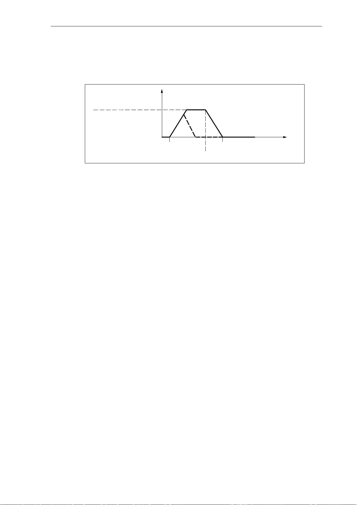
Positioning from the standstill, spindle is synchronized
The spindle has already been rotated by at least one spindle revolution using M3 or M4 and
has then be stopped with M5.
Spindle (S1)
5.2 Spindle modes
Sequence
Speed
(1/min)
MD 35300:
SPIND_POSCTRL_VELO
(Position controller switch-on speed)
Start at: SPOS=...
Fig. 5-5 Positioning with the spindle stopped and synchronized
Phases 1 to 4:
2
3a
1
3
4a
Position reached
Brake threshold point
4
Time (s)
The spindle is traversed time-optimized until the programmed time is reached. Depending on
the related boundary conditions, the spindle will pass the phases 1 - 2 - 3 - 4 or 1 - 3a - 4a.
Phase 1: SPOS will switch the spindle to position control mode. The acceleration from the
MD 35210: GEAR_STEP_POSCTRL_ACCEL (acceleration in position control mode) becomes active. The direction of rotation is determined by the present distance to go (type of path
specification with SPOS). The limit frequency set in MD 35300: SPIND_POSCTRL_VELO
(position control threshold speed) will not be exceeded.
The calculation of the distance to be traversed to the target position will be carried out. If the
target point can be reached from this phase immediately, it is continued with phases 3a and
4a, instead of phase 2.
Spindle reset
Notes
Phase 2: The system has been accelerated up to the speed entered in
MD 35300: SPIND_POSCTRL_VELO (position controller threshold speed). The brake threshold point calculation will recognize at which time the programmed spindle position
(SPOS=...) can be approached at the acceleration stored in MD 35210:
GEAR_STEP_POSCTRL_ACCEL .
Phase 3 and phase 4: “Braking” and “Position reached” have the same sequence as with a
non-synchronized spindle.
The positioning process can be canceld using the IS ”Delete distance to go/spindle reset”
(V380x0002.2). However, the spindle will remain in positioning mode.
The spindle override switch continues to apply in Positioning mode.
The positioning (SPOS) can be canceled either with “Reset” or “NC STOP”.
SINUMERIK 802D, 802D base line
6FC5 697-2AA10-0BP2 (11.03) (DF)
5-93
Page 94

Spindle (S1)
5.2 Spindle modes
5.2.4 Spindle mode: Axis mode
When axis mode?
For certain machining tasks on turning machines, such as end face machining via TRANSMIT
or peripheral surface machining via TRACYL, the spindle must be run as a rotary axis.
If TRANSMIT or TRACYL is not activated, standard rotary axis functions can be executed. In
this case, the programming is carried out under the rotary axis address, e.g. C.
Prerequisites
The spindle can be switched from the spindle mode to the axis mode (rotary axis) if a common
motor is used both for the spindle and for the axis modes.
The axis mode requires a position actual-value encoder.
Activation/deactivation
Set the spindle to the position-controlled mode (positining mode):
N10 SPOS=0
If the spindle is synchronized, switching to the position-controlled mode is also possible via
M70 or SPCON.
Now, the axis can be traversed in the program as a rotary axis:
N20 G94 G1 C124.4 F4000 ; Feedrate F: 4,000 degrees/min
Switching back to the speed-controlled spindle mode is performed by programming
N100 M3 ; or M4, M5, M41 ... M45 or SPCOF
Special features
The feedrate override factor is effective.
By default, RESET will not quit the axis mode.
The IS “Spindle/no axis” (V390x 0000.0) is set to zero.
The axis mode can be enabled in any gear stage.
If the axis mode is active, the gear stage cannot be changed.
In the axis mode, the MD of the parameter set with index zero apply in order to be able to
make adaptations in this mode.
5-94
SINUMERIK 802D, 802D base line
6FC5 697-2AA10-0BP2 (11.03) (DF)
Page 95

5.3 Synchronizing
Why synchronizing?
To ensure that the control system exactly finds the 0 degree position after the control system
has been turned on, the control system must be synchronized with the position encoder of the
spindle. Only a synchronized spindle can perform thread cutting or positioning.
As far as axes are concerned, this process is called “referencing” (see Chapter “Reference
Point Approach”).
Mounting locations of the position measuring systems
directly on the motor plus BERO switch on the spindle (zero marker encoder)
directly on the spindle
on the spindle above the resolver gearbox plus BERO switch on the spindle
Synchronization options
Spindle (S1)
5.3 Synchronizing
After the control system has been turned on, the spindle can be synchronized as follows:
The spindle is started at a spindle speed (S function) and with a spindle rotation direction
(M3 or M4) and synchronizes itself with the next zero mark of the position measuring system or BERO signal. The 0-degree position is offset by MD 34080: REFP_MOVE_DIST
+ MD 34090: REFP_MOVE_DIST - MD 34100: REFP_SET_POS.
Note: To offset the 0-degree position, only use MD 34080: REF_MOVE_DIST. The monitoring using MD 34060: REFP_MAX_MARKER_DIST should be set to two spindle revolutions (720 degrees).
by programming SPOS=... from different states (see Section 5.2.3 “Spindle mode: Positio-
ning mode”)
In JOG mode, the spindle is started in speed control mode using the direction keys and
synchronizes itself with the next zero mark of the position measuring system or the BERO
SIGNAL.
Value acceptance
When synchronizing the spindle, the corresponding reference point value and a resulting offset of the reference point (if any) is accepted from MD 34100: REFP_SET_POS[0] (default
value =0). These offsets (machine data) act independently of the connected measuring system and are described in the Section “Reference point approach”.
Max. encoder frequency exceeded
If in spindle mode “Control mode” the spindle reaches a speed (large S value programmed)
that is greater than the max. encoder frequency (the max. speed of the encoder may not be
exceeded), the synchronization gets lost. The spindle goes on rotating, but with reduced functionality.
If thereafter a speed is reached which is below the maximum encoder limit frequency (smaller
S value programmed, spindle override switch changed, etc.), the spindle synchronizes itself
automatically from the next zero mark signal.
SINUMERIK 802D, 802D base line
6FC5 697-2AA10-0BP2 (11.03) (DF)
5-95
Page 96

Spindle (S1)
5.4 Gear stage change
Resynchronizing
In the following case, however, the position measuring system of the spindle must be resynchronized:
The position measuring system is mounted on the motor, a BERO (clearance sensor for synchronization signal) is mounted on the spindle, and the gear stage is changed. The synchronization is internally initiated when the spindle rotates at the new gear stage.
5.4 Gear stage change
Number of gear stages
5 gear steps can be configured for the spindle. If the spindle motor is mounted directly on the
spindle (1:1) or via a transmission ratio that cannot be changed, MD 35010:
GEAR_STEP_CHANGE_ENABLE (gear stage change possible) must be set to zero.
Motor
speed
(1/min)
Max. motor speed
0
Can be defined by MD:
g
n
g
g
n
g
g
1min
Gear
stage 1
1max
1min
1max
2max
2min
2max
With automatic gear stage change,
this speed range will not be utilized
in gear stage 1.
Gear
stage 2
n
1max
g
1max
g
2min
...max. spindle speed of the 1st gear stage
... min. spindle speed of the 1st gear stage
for autom. gear stage selection
...max. spindle speed of the 1st gear stage
for autom. gear stage selection
...max. spindle speed of the 2nd gear stage
... min. spindle speed of the 2nd gear stage
for autom. gear stage selection
...max. spindle speed of the 2nd gear stage
for autom. gear stage selection
Spindle speed (1/min)
n
2max
g
2max
Fig. 5-6 Gear stage change with gear stage selection
Preselecting a gear stage
A gear stage can be defined:
as a fixed gear stage by the part program (M41 to M45)
automatically by the programmed spindle speed (M40)
If M40 is active and automatic gear stage selection is to be carried out using an S word, the
spindle must be in control mode. Otherwise, the gear stage change is denied, and alarm
22000 “No gear stage change possible” is set.
5-96
SINUMERIK 802D, 802D base line
6FC5 697-2AA10-0BP2 (11.03) (DF)
Page 97

M41 to M45
M40
Spindle (S1)
5.4 Gear stage change
The gear stage can be firmly defined in the part program using M41 to M45. If a gear stage is
specified using M41 to M45, which is not equal to the current (actual) gear stage, the IS
”Switch over gear” (V390x2000.3) and the IS ”Set gear stage A to C” (V390x2000.0 bis .2) are
set. The programmed spindle speed (S function) refers to the gear stage defined as a fixed
gear stage. If a spindle speed is programmed which is above the max. speed of the firmly determined gear stage, a limitation of the max. speed of the gear stage is carried out, and the IS
”Setpoint speed limited” (V390x2001.1) is set.
M40 in the part program serves to define the gear stage by the control system automatically. A
check is carried out to see whether the programmed spindle speed (S function) is possible. If
a gear stage is found which is not equal to the current (actual) gear stage, the IS ”Switch over
gear” (V390x2000.3) and the IS ”Set gear stage A to C” (V390x2000.0 bis .2) are set.
The automatic gear stage selection is carried out such that first the programmed spindle
speed is compared with the min. and max. speed of the current gear stage. If the comparison
is positive, no new gear stage is set. If the comparison is negative, the comparison is carried
out for all 5 gear steps (starting with gear stage 1) until it is positive. If the comparison is not
positive even for the 5th gear stage, no gear stage change is carried out. The speed is limited,
if necessary, to the maximum speed of the current gear stage, and/or is raised to the minimum
speed of the current gear stage, and the IS ”Setpoint speed limited” (V390x2001.1) and/or
”Setpoint speed increased” (V390x2001.2) is set).
Speed
(1/min)
MD35100:SPIND_VELO_LIMIT:
MD35130:GEAR_STEP_MAX_VELO_LIMIT[2]:
MD35110:GEAR_STEP_MAX_VELO[2]:
MD35130:GEAR_STEP_MAX_VELO_LIMIT[1]:
MD35110:GEAR_STEP_MAX_VELO[1]:
MD35120:GEAR_STEP_MIN_VELO[2]:
MD35120:GEAR_STEP_MIN_VELO_LIMIT[2]:
MD35120:GEAR_STEP_MIN_VELO[1]:
MD35120:GEAR_STEP_MIN_VELO_LIMIT[1]:
Max. speed for gear stage change 2
Max. speed of gear stage 1
Max. speed for gear stage change 1
Min. speed of gear stage change 2
Min. speed for gear stage change 1
Min. speed for gear stage 1
Max. spindle speed
Max. speed of gear stage 2
Min. speed for gear stage 2
0
Fig. 5-7 Example of speed ranges with automatic gear stage selection (M40)
Gear
stage 1
Gear
stage 2
SINUMERIK 802D, 802D base line
6FC5 697-2AA10-0BP2 (11.03) (DF)
5-97
Page 98

Spindle (S1)
5.4 Gear stage change
Changing the gear stage when the spindle is at a standstill
It is possible to switch over to a new gear stage while the spindle is at a standstill.
After the new gear stage has been preselected by M40 and the spindle speed by M41 to M45,
the IS ”Set gear steps A to C” (V390x2000.0 bis .2) and IS ”Switch over gear” (V390x2000.4)
are set. Depending on to which time the IS ”Oscillation speed” (V380x2002.5) is set, the
spindle brakes down to a standstill at the acceleration defined for oscillation or at the acceleration defined for speed control mode/position control mode.
The next block in the part program after a gear stage switchover using M40 and S value or
M41 to M45 will not be executed (same effect as if the IS ”Read disable“ (V32000006.1) would
be set.).
When the spindle is at a standstill (IS ”Axis/spindle stop” (V390x0001.4) ), the oscillation can
be switched on by the IS ”Oscillation speed” (V380x2002.5). After the new gear stage has
been switched on, the PLC user sets the IS ”Actual gear stage” (V380x2000.0 bis .2) and IS
”Gear is switched over” (V380x2000.3). The gear stage change is considered completed
(spindle mode “Oscillation mode“ is deselected) and the spindle is switched to the parameter
set of the new actual gear stage. The spindle accelerates to the last programmed spindle
speed in the new gear stage (provided that M3 or M4 is active). The IS ”Switch over gear”
(V390x2000.3) is reset by the NCK, whereupon the PLC user has to reset the IS ”Gear is switched over” (V380x2000.3). The next block in the part program can be executed.
5-98
SINUMERIK 802D, 802D base line
6FC5 697-2AA10-0BP2 (11.03) (DF)
Page 99

Typical sequence of a gear stage change:
IS ”Control mode”
IS ”Oscillation mode”
Spindle (S1)
5.4 Gear stage change
Programmed S value
1000 1300
IS ”Gear is switched over”
IS ”Switch over gear”
IS ”Set gear stage”
21
IS ”Spindle in set range”
IS ”Spindle stopped”
IS ”Actual gear stage”
IS ”Oscillation speed”
1
12
1st gear stage engaged
2nd gear stage engaged
Internal feed disable
T1 T2
Spindle speed
IS ”Spindle STOP” 0
t1 t2
t1 The NCK recognizes a new gear stage by programming S1300 (2nd gear stage),
sets the IS ”Switch over gear” and disables the execution of the next part program block.
t3 t4
t2
The spindle is at a standstill and oscillation is started (oscillation by the NCK).
The IS ”Oscillation speed” must be set at the time t2 at the latest.
t3
The new gear stage is engaged. The PLC user transfers the new (actual)
gear stage to the NCK and sets the IS ”Gear is switched over”.
t4
The NCK accepts the IS ”Switch over gear”, completes oscillation,
enables the next part program block for execution and accelerates the spindle
to the new S value (S1300).
Fig. 5-8 Gear stage change with the spindle stopped
SINUMERIK 802D, 802D base line
6FC5 697-2AA10-0BP2 (11.03) (DF)
5-99
Page 100
Spindle (S1)
p,
5.4 Gear stage change
Set of parameters
One set of parameters each is provided for each of the 5 gear stages. The appropriate parameter set is enabled by the IS “Actual gear stage A” to “... C” (V380x2000.0 to .2). The parameter set assignment is as follows:
Parameter set,
Index
n
0 - Data for axis mode
1 000
2 010 Data for 2nd gear stage
3 011 Data for 3rd gear stage
4 100 Data for 4th gear stage
5 101 Data for 5th gear stage
PLC interface, coding for the
IS “Actual gear stage A”,
to “...C”
CBA
001
Data of data record Contents,
Data for 1st gear stage
machine data
for
servo gain factor,
monitoring functions,
min/max speed,
accelerations
The machine data that are contained in a parameter set are especially marked in Section
3.7.2 “Machine data”. For each gear stage, the following machine data are added to parameter set index n (n=1 -> 1st gear stage of the spindle, etc.):
MD 35110: GEAR_STEP_MAX_VELO[n]
MD 35120: GEAR_STEP_MIN_VELO[n]
MD 35130: GEAR_STEP_MAX_VELO_LIMIT[n]
MD 35140: GEAR_STEP_MIN_VELO_LIMIT[n]
MD 35200: GEAR_STEP_SPEEDCTRL_ACCEL[n]
MD 35210: GEAR_STEP_POSCTRL_ACCEL[n]
MD 35310: SPIND_POSIT_DELAY_TIME[n]
5-100
SINUMERIK 802D, 802D base line
6FC5 697-2AA10-0BP2 (11.03) (DF)
 Loading...