

Page 1

Diagnostics Guide 10/2002 Edition
sinumerik
SINUMERIK 802D
SINUMERIK 802D base line
Page 2

Page 3

SINUMERIK 802D
Diagnostics Guide
Alarms
Glossary /
Abbreviations
1
2
Valid for
Control Software version
SINUMERIK 802D as of 1
10.02 Edition
Page 4

SINUMERIK documentation
Printing history
Brief details of this edition and previous editions are listed below.
The status of each edition is shown by the code in the ”Remarks” column.
Status code in the ”Remarks” column:
A New documentation.. . . .
B Unrevized reprint with new Order No.. . . .
C Revised edition with new status. . . . .
If actual changes have been made on the page since the last edition,
this is indicated by a new edition coding in the header on that page.
Edition Order No. Remarks
11.00 6FC5698-2AA20-0BP0 A
10.02 6FC5698-2AA20-0BP1 C
This Manual is included on the documentation on CD-ROM (DOCONCD)
Edition Order No. Remarks
11.02 6FC5298-6CA00-0BG3 C
Trademarks
SIMATICr, SIMATIC HMIr, SIMATIC NETr, SIROTECr, SINUMERIKr and SIMODRIVEr are registered
trademarks of Siemens. Third parties using for their own purposes any other names in this document which
refer to trademarks might infringe upon the rights of trademark owners.
This documentation was produced using Interleaf 7.0.
Subject to change without prior notice.
The reproduction, transmission or use of this document or its
contents is not permitted without express written authority. Offenders
will be liable for demages. All rights, including rights created by patent
grant or registration of utility model or design, are reserved.
Siemens AG 2002. All rights reserved.
Printed in the Federal Republic of Germany
Other functions not described in this documentation might be
executable in the control. This does not, however, represent an
obligation to supply such functions with a new control or when
servicing.
We have checked that the contents of this document correspond to
the hardware and software described. Nonetheless, differences might
exist and therefore we cannot guarantee that they are completely
identical. The information contained in this document is, however,
reviewed regularly and any necessary changes will be included in the
next edition. We welcome suggestions for improvement.
Siemens-AktiengesellschaftOrder No. 6FC5698-2AA20-0BP1
Page 5
10.02
Preface
The present description is intended to be used as a reference manual. It
allows the operator on the machine tool to:
- access special cases in the operation of the machine correctly;
- to learn the response of the system/installation to the particular special case;
- to use the possibilities of continuing work after the special case;
- to follow notes for further references.
Scope
Object of the present description are the alarms occurring in the areas
NC kernel (NCK), Profibus, cycles and PLC.
Further alarms may occur in the HMI area (Human Machine Interface).
They are announced to the user by self-explaining alarm lines displayed
on the operator panel. These alarms are not part of this Diagnostics
Guide.
For special cases in conjunction with the integrated PLC, please refer to
the relevant SIMATIC S7-200 system documentation.
Sorting
Safety
NC alarms
The alarms are sorted in the Diagnostics Guide by ascending alarm
numbers with gaps between them.
Danger
Please always check the situation of the particular system/installation
carefully on the basis of the alarms occurred. Eliminate the causes for
the occurrence of the alarms and acknowledge them as described.
Otherwise, danger will result for machine, workpiece, saved settings
and - under certain circumstances - even for your health.
Table 1_1 Alarm number ranges
000 000 - 009 999 General alarms
010 000 - 019 999 Channel alarms
020 000 - 029 999 Axis / spindle alarms
030 000 - 099 999 Functional alarms
060 000 - 064 999 SIEMENS cycle alarms
065 000 - 069 999 User cycle alarms
© Siemens AG 2002 All Rights Reserved 6FC5698-2AA20-0BP1
802D (DG)
v
Page 6
10.02
HMI alarms/messages
PLC alarms/messages
Table 1_2 Alarm number ranges (cont'd.)
100 000 - 100 999 Basic system HMI0
101 000 - 101 999 Diagnosis
102 000 - 102 999 Services
103 000 - 103 999 Machine
104 000 - 104 999 Parameters
105 000 - 105 999 Programming
106 000 - 106 999 Reserve
107 000 - 107 999 OEM
110 000 - 110 999 Reserved
120 000 - 120 999 Reserved
Table 1_4 Alarm number ranges (cont'd.)
400 000 - 499 999 General alarms
700 000 - 799 999 User area
6FC5698-2AA20-0BP1 © Siemens AG 2002 All Rights Reserved
vi 802D (DG)
Page 7

10.02
Contents
Alarms .......................................................................................................................................... 9
1.1
1.2
13
1.4
15
1.6
Glossary / Abbreviations ........................................................................................................ 209
2.1
2.2
Overview of NC alarms ...................................................................................... 10
Profibus Alarms................................................................................................ 180
Cycle Alarms|................................................................................................... 187
ISO Alarms....................................................................................................... 197
PLC Alarms...................................................................................................... 199
Action List ........................................................................................................ 202
Abbreviations ................................................................................................... 209
Glossary........................................................................................................... 213
© Siemens AG 2002 All Rights Reserved 6FC5698-2AA20-0BP1
802D (DG)
vii
Page 8

10.02
6FC5698-2AA20-0BP1 © Siemens AG 2002 All Rights Reserved
viii 802D (DG)
Page 9

10.02 1 Alarms
Alarms
1
Alarms with alarm number 1xxx are system errors that indicate internal
error states. The internal error number transmitted provides the devel-
oper important information with regard to the error cause and the error
location.
These system errors are not described in detail. If they occur with the
supplied control systems at all, please contact the following hotline,
specifying the alarm number, the alarm text and the internal system
error number contained therein:
Hotline Germany
Siemens AG, A&D MC
Tel. +49 (0) 180 525 80 08
Fax +49 (0) 180 525 80 09
Hotline China
Siemens Numerical Control Ltd.
Development & Engineering Division
Tel. (025) 2 18 18 88 (Ext. 305)
Fax (025) 2 18 16 66
© Siemens AG 2002 All Rights Reserved 6FC5698-2AA20-0BP1
802D (DG) 1-9
Page 10

10.02 1 Alarms
10.02
1.1 Overview of NC alarms
2000
Explanation
Reaction
Remedy
Program continuation
by
2001
Explanation
Reaction
Remedy
Program continuation
by
Sign-of-life monitoring PLC
The PLC must provide a sign of life within a defined period of time. If not, this
alarm is generated.
NC Start inhibited.
NC not ready.
NC Stop at alarm.
Alarm display.
Interface signals are set.
This alarm also occurs as a consequence of PLC Stop.
(PLC Stop via Programming Tool,
PLC Stop from start-up switch,
PLC Stop caused by an alarm)
If none of the above mentioned cases exists, please contact the hotline indicated in the beginning of this publication and specify the operating system
error number.
Power ON
PLC not booted
The PLC must provide at least one sign of life within the defined period of time
after POWER ON.
NC Start inhibited.
NC not ready.
NC Stop at alarm.
Alarm display.
Interface signals are set.
Contact the hotline indicated in the beginning of this publication.
Power ON
2140
Explanation
Reaction
Remedy
Program continuation
by
3000
Explanation
Reaction
6FC5698-2AA20-0BP1 © Siemens AG 2002 All Rights Reserved
1-10 802D (DG)
The current position of the service switch will clear the SRAM with the
next POWER ON (general reset active)
The initialization switch is currently set to "General reset". As a consequence,
the SRAM of the module is cleared with the next module reset; as a result, the
NC data memory is lost.
Alarm display.
Interface signals are set.
NC not ready.
Reset the initialization switch back to "1".
Use the "Cancel" key to cancel the alarm. No further operation required.
EMERGENCY STOP
The EMERGENCY STOP request is present at the NC/PLC interface
(V 26000000.1).
NC Start inhibited.
NC not ready
Page 11

10.02 1 Alarms
NC Stop at alarm
Alarm display
Interface signals are set.
Remedy
Program continuation
by
Check whether an EMERGENCY STOP cam has been approached or an
EMERGENCY STOP button has been tripped. Check the PLC user program.
Correct the EMERGENCY STOP cause and acknowledge EMERGENCY
STOP via the PLC/NC user interface (V 26000000.2).
Use the RESET key to cancel the alarm. Restart the part program.
4000
Explanation
Reaction
Remedy
Program continuation
by
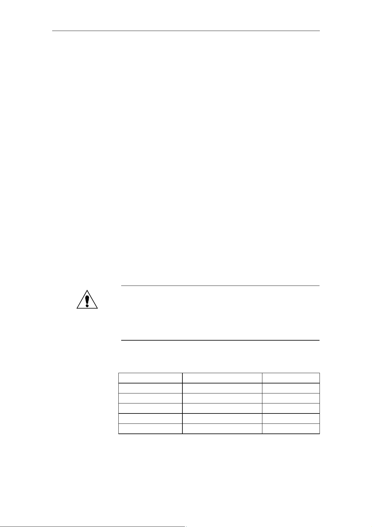
Channel %1 machine data %2 contains a gap in the axis assignment
%1 = channel number
%2 = string: MD identifier
The assignment of a machine axis to a channel using the MD 20070
AXCONF_MACHAX_USED must be carried out without gaps. Any gaps will be
detected when the system boots (POWER ON) and be displayed as an alarm.
Alarm display.
Interface signals are set.
NC not ready.
NC Start inhibited.
NC Stop at alarm.
Please inform the authorized personnel/customer service.
Configure MD 20070 AXCONF_MACHAX_USED for the axis assignment of
the channel without gaps, i.e. with ascending axis indices, a machine axis has
to be assigned until zero (no machine axis) is entered for the first time. In this
case, all MDs that have higher indices must also be loaded with zero.
The sequence order of the machine numbers is not relevant.
Channel
Index
0 1 AXCONF_MACHAX_USED [CH1, AX1] = 1
1 2 AXCONF_MACHAX_USED [CH1, AX2] = 2
2 3 AXCONF_MACHAX_USED [CH1, AX3] = 3
3 4 AXCONF_MACHAX_USED [CH1, AX4] = 4
4 5 AXCONF_MACHAX_USED [CH1, AX5] = 5
Assignment of the channel axes to the machine axes
Power ON
1st
Channel
Machine Axis Number
4002
Explanation
© Siemens AG 2002 All Rights Reserved 6FC5698-2AA20-0BP1
802D (DG) 1-11
Channel %1 machine data %2[%3] contains an axis not defined in the
channel
%1 = channel number
%2 = string: MD identifier
%3 = index: MD array index
Only axes activated in the channel via MD 20070
[kx]=m
may be declared geometry axes via
MD 20050 AXCONF_GEOAX_ASSIGN_TAB [gx]=k.
gx ... Geometry axis index k ... Channel axis no.
kx ... Channel axis index m ... Machine axis no.
AXCONF_MACHAX_USED
Page 12

10.02 1 Alarms
10.02
Reaction
Remedy
Program continuation
by
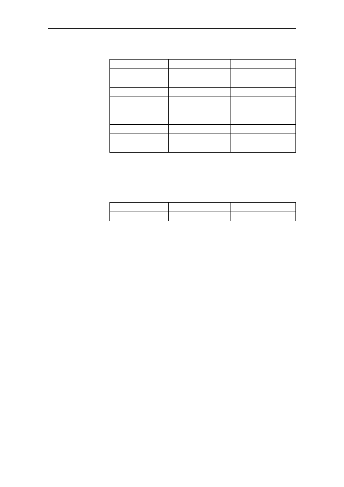
MD 20050
AXCONF_GEOAX_ASSIGN_TAB
(contains channel axis no. k) (contains machine axis no. m)
Geometry Axis
Index
1. Channel Channel Axis
MD 20070
AXCONF_MACHAX_USED
Index
1. Channel
0 1 0 1
1 2 1 2
2 3 2 3
3 4
4 5
Assignment of the geometry axes to the channel axes
Alarm display.
Interface signals are set.
NC not ready.
NC Start inhibited.
NC Stop at alarm.
Please inform the authorized personnel/customer service.
Check MD 20050
AXCONF_GEOAX_ASSIGN TAB
and
MD 20070 AXCONF_MACHAX_USED and correct them if necessary.
The basis is the MD array MD 20070 AXCONF_MACHAX_USED in which the
machine axis number to be controlled by this channel is entered channelspecifically. The resulting "channel axes" are assigned a name by MD 20080
AXCONF_CHANAX_NAME_TAB and assigned to a geometry axis via MD
20050 AXCONF_GEOAX_ASSIGN_TAB by entering the relevant channel axis
in this MD array for each geometry axis.
Power ON
4004
Explanation
Reaction
Remedy
Program continuation
by
4010
Explanation
Channel %1 machine data %2 axis %3 defined as a geometry axis repeatedly
%1 = channel number
%2 = string: MD identifier
%3 = axis index
An axis may be defined as a geometry axis only once.
Alarm display.
Interface signals are set.
NC not ready.
NC Start inhibited.
NC Stop at alarm.
Correct MD 20050
AXCONF_GEOAX_ASSIGN_TAB
.
Power ON
Power ON
Machine data %1[%2] contains an illegal identifier
%1 = string: MD identifier
%2 = index: MD array index
When defining the names for: machine axes, one of the following syntax rules
has been violated for the identifier to be entered:
6FC5698-2AA20-0BP1 © Siemens AG 2002 All Rights Reserved
1-12 802D (DG)
Page 13

10.02 1 Alarms
1. The identifier must be an NC address letter (A, B, C, I, J, K, U, V, W, X, Y,
Z), possibly with a numerical extension.
2. The identifier must start with 2 random uppercase letters, but not with the
$ character (reserved).
3. The identifier must not be a vocabulary word of the NC language (e.g.
SPOS).
Reaction
Remedy
Program continuation
by
Alarm display.
Interface signals are set.
NC not ready.
NC Start inhibited.
NC Stop at alarm.
Please inform the authorized personnel/customer service.
Enter the identifier for user-defined names in the displayed MD using the correct syntax.
Machine axes: MD 10000 AXCONF_MACHAX_NAME_TAB
Power ON
4011
Explanation
Reaction
Remedy
Program continuation
by
Channel %1 Machine data %2[%3] contains an illegal identifier
%1 = channel number
%2 = string: MD identifier
%3 = index: MD array index
When defining the names in the channel-specific tables for geometry axes and
channel axes, one of the following syntax rules has been violated for the identifier to be entered:
1. The identifier must be an NC address letter (A, B, C, I, J, K, U, V, W, X, Y,
Z), possibly with a numerical extension.
2. The identifier must start with 2 random uppercase letters, but not with the
$ character (reserved for system variables).
3. The identifier must not be a vocabulary word of the NC language (e.g.
SPOS).
Alarm display.
Interface signals are set.
NC not ready.
NC Start inhibited.
NC Stop at alarm.
Please inform the authorized personnel/customer service.
Enter the identifier for user-defined names in the displayed MD using the correct syntax.
Geometry axes: MD 20060 AXCONF_GEOAX_NAME_TAB
Channel axes: MD 10000
Power ON
AXCONF_MACHAX_NAME_TAB
4020
Explanation
Reaction
© Siemens AG 2002 All Rights Reserved 6FC5698-2AA20-0BP1
802D (DG) 1-13
Identifier %1 used repeatedly in machine data %2
%1 = string: identifier
%2 = string: MD identifier
When defining the names in the NC tables (arrays) for machine axes, an
identifier was used which already exists in the control system.
Alarm display.
Interface signals are set.
NC not ready.
Page 14

10.02 1 Alarms
10.02
NC Start inhibited.
NC Stop at alarm.
Remedy
Program continuation
by
Please inform the authorized personnel/customer service.
Select a string for the identifier to be entered which is not yet used in the system (max. 32 characters).
The RESET key must be used in all channels of this mode group to cancel this
alarm.
4021
Explanation
Reaction
Remedy
Program continuation
by
4030
Explanation
Reaction
Remedy
Program continuation
by
Channel %1 Identifier %2 used repeatedly in machine data %3
%1 = channel number
%2 = string: Identifier
%3 = string: MD identifier
When defining the names in the channel-specific tables for geometry axes
and channel axes, an identifier was used which already exists in the control
system.
Alarm display.
Interface signals are set.
NC not ready.
NC Start inhibited.
NC Stop at alarm.
Please inform the authorized personnel/customer service.
Select a string for the identifier to be entered which is not yet used in the system (max. 32 characters).
Power ON
Channel %1 Missing identifier in machine data %2[%3]
%1 = channel number
%2 = string: MD identifier
%3 = index: MD array index
Due to the axis configuration in MD 20070 AXCONF_
MACHAX_USED and MD 20050 AXCONF_GEOAX_ASSIGN_TAB,
an axis identifier is expected for the MD displayed.
Alarm display.
Interface signals are set.
NC not ready.
NC Start inhibited.
NC Stop at alarm.
Please inform the authorized personnel/customer service.
Check the axis configuration and enter the missing axis identifier in the MD or if you wish the axis to be omitted - specify machine axis 0 for this channel axis
in MD 20070 AXCONF_MACHAX_USED. If the axis is a geometry axis which
will not be used (with exclusively 2-axis machining, e.g. with turning machines),
the channel axis 0 must additionally entered in MD 20050
AXCONF_GEOAX_ASSIGN_TAB for the appropriate geometry axis.
Power ON
6FC5698-2AA20-0BP1 © Siemens AG 2002 All Rights Reserved
1-14 802D (DG)
Page 15

10.02 1 Alarms
4032
Explanation
Reaction
Remedy
Program continuation
by
4040
Explanation
Reaction
Remedy
Program continuation
by
Channel %1 Wrong identifier for transverse axis in %2
%1 = channel number
%2 = string: MD identifier
Due to the axis configuration in MD 20150 GCODE_RESET_VALUES or MD
DIAMETER_AX_DEF
20100
specified place.
Alarm display
Interface signals are set
NC Stop at alarm
NC not ready
NC Start inhibited
Please inform the authorized personnel/customer service.
Add the correct identifier.
Power ON
Channel %1 axis identifier %2 inconsistent with machine data %3
%1 = channel number
%2 = string: Axis identifier
%3 = string: MD identifier
The use of the axis identifier specified in the displayed MD is not consistent
with the axis configuration of the channel specified in MD 20070
AXCONF_MACHAX_USED
MD 20050 AXCONF_GEOAX_ASSIGN_TAB.
Alarm display.
Interface signals are set.
NC not ready.
NC Start inhibited.
NC Stop at alarm.
Please inform the authorized personnel/customer service.
Check the identifiers used in MD 10000 AXCONF_
MACHAX_NAME_TAB, MD 20080 AXCONF_CHANAX_NAME_TAB and/or
MD 20050 AXCONF_GEOAX_NAME_TAB and correct them if necessary.
Power ON
, a transverse axis identifier is expected in the
and
4050
Explanation
Reaction
© Siemens AG 2002 All Rights Reserved 6FC5698-2AA20-0BP1
802D (DG) 1-15
NC code identifier %1 was not reconfigured to %2
%1 = string: Old identifier
%2 = string: New identifier
The NC code could not be renamed for one of the following reasons:
• The old identifier does not exist any more.
• The new identifier is assigned to a different type area.
NC codes/vocabulary words can be reconfigured via machine data provided
that the type area is not left.
Type 1: "Real" G codes: G02, G17, G33, G64, ...
Type 2: Known G codes: CIP, TRANS, ...
Alarm display.
Interface signals are set.
NC not ready.
NC Start inhibited.
NC Stop at alarm.
Page 16

10.02 1 Alarms
10.02
Remedy
Program continuation
by
4060
Explanation
Reaction
Remedy
Program continuation
by
Please inform the authorized personnel/customer service.
Correct MD 10712 NC_USER_CODE_CONF_NAME_TAB (protection level 1).
The list must be structured as follows:
Even address: Identifier to be changed
followed by an odd address: New identifier
e.g.: NC_USER_CODE_CONF_NAME_TAB [10] = "ROT"
NC_USER_CODE_CONF_NAME_TAB [11] = " "
will cancel the ROT function in the control system
Power ON
Default machine data have been loaded
Booting with the default values by:
• operator action (e.g. start-up switch)
• MD 11200 INIT_MD
• loss of the retentive data
• operator action - booting with saved data, without saving the data first
Alarm display.
After the default machine data have been loaded, the particular MD for your
particular system/installation must be entered/loaded.
Use the "Cancel" key to cancel the alarm. Reload your own machine data.
4062
Explanation
Reaction
Remedy
Program continuation
by
4065
Explanation
Reaction
Remedy
Program continuation
by
Data backup copy has been loaded
The used data saved to flash have been loaded into the SRAM.
Alarm display.
Reload your own machine data.
Use the RESET key to cancel the alarm.
Battery-backed memory is restored from backup copy (risk of data loss !)
When booting, a possible inconsistency has been detected in the batterybacked memory.
The battery-backed memory was initialized using the last backup copy. As a
result, the changes in the battery-backed memory carried out since the last
update of the backup copy are lost. The cause of this procedure is to be
searched for in exceeding of the buffer time. Please make sure that the required on-time of the control system, which is specified in your Start-up Guide,
is not exceeded.
The current backup copy of the battery-backed memory was created using the
internal data backup carried out last using the softkey "Save data" in the HMI.
Alarm display
Interface signals are set.
NC Start inhibited
Restart the control system.
6FC5698-2AA20-0BP1 © Siemens AG 2002 All Rights Reserved
1-16 802D (DG)
Page 17

10.02 1 Alarms
4070
Explanation
Reaction
Remedy
Program continuation
by
Unit machine data changed
The control system uses internal physical units (mm, degrees, s, for distances
to go, velocities, accelerations and the like). With programming or data backup, some of these values are input/output using other units (rpm, m/s2, etc.).
The conversion is carried out using scaling factors which can be entered (system-specific MD array 10230 SCALING_FACTORS USER_DEF[n] (n ... index
numbers 0 ... 10) if the relevant masking bit is set to "1".
If the masking bit is set to "0", the scaling is carried out using the internal default factors.
The following machine data influence the scaling of other MDs:
MD 10220
MD 10230 SCALING_FACTORS_USER_DEF
MD 10240 SCALING_SYSTEM_IS_METRIC
MD 10250
MD 30300 IS_ROT_AX
After these data have been changed, the NC must be rebooted. Only then the
input of dependent data will be executed correctly.
Alarm display.
Please inform the authorized personnel/customer service.
If the alarm has been displayed after downloading a consistent MD file, the
download operation must be repeated and the NC is rebooted. (Scalingdependent machine data in the file are always put in front of the scaling factors).
Use the "Cancel" key to cancel the alarm. No further operation required.
SCALING_USER_DEF_MASK
SCALING_VALUE_INCH
4075
Explanation
Reaction
Remedy
Program continuation
by
4076
Explanation
Machine data %1 (and possible further) not changed due to missing access rights %2
%1 = string: MD identifier
%2 = write protection level of the MD
When executing a TOA file, it has been tried to program a data whose protection level is higher than the access authorization currently set at the control
system.
The relevant data has not been programmed.
This alarm is only generated with the first write access violation detected.
Alarm display.
Either set the required access level via the password or delete the appropriate
machine data from the MD file.
Use the "Cancel" key to cancel the alarm. No further operation required.
%1 Machine data could not be changed with access right %2
%1 = number of MD
%2 = set access right
When executing a TOA file, it has been tried to program a data whose protection level is higher than the access authorization currently set at the control
system.
The appropriate data have not been programmed.
This alarm is issued when acknowledging alarm 4075. It can only be canceled
with POWER ON.
© Siemens AG 2002 All Rights Reserved 6FC5698-2AA20-0BP1
802D (DG) 1-17
Page 18

10.02 1 Alarms
10.02
Reaction
Remedy
Program continuation
by
4077
Explanation
Reaction
Remedy
Program continuation
by
Alarm display.
Either set the required access level via the password or using the keyswitch or
delete the appropriate machine data from the MD file.
Power ON
New value %1 of MD %2 not set; requests %3 bytes too much %4 memory.
%1 = new value of the machine data
%2 = machine data number
%3 = number of bytes requested in excess
%4 = type of memory
It was tried to assign the specified memory-configuring machine data a new
value.
The change will not be executed, since it would result in deleting the user
memory. The change requires more user memory than provided.
The third parameter specifies the number of bytes by which the maximum user
memory has been exceeded.
The fourth parameter specifies the type of the memory whose limit is exceeded:
"D" stands for the dynamic or non-backed user memory (there are, e.g. the
LUD variables, this also includes the IPO buffer size). The size of this memory
type is defined by the current memory configuration and by the value of
MD18210
"S" stands for the static or battery-backed user memory (typically, there are the
part programs, but also the compensation data, R parameters, tool data); this
memory type is also defined by the current memory configuration and by the
value of MD 18230 MM_USER_MEM_BUFFERED.
Alarm display.
If the change was not desired, then simply continue.
In this case, the alarm will not have any negative influence.
How this error is corrected depends on the access right and on the current NC
memory configuration:
The change as planned to be done is not possible in this way -> try once more
using a smaller value. When doing so, watch how the value of the byte number
changes.
Buying more memory? This possibility depends on the model you are using.
The NC user memory is possible set smaller than possible. Provided the appropriate access right, the MD (see above) can be changed.
Use the "Cancel" key to cancel the alarm. No further operation required.
MM_USER_MEM_DYNAMIC
.
4090
Explanation
Reaction
Remedy
Program continuation
by
6FC5698-2AA20-0BP1 © Siemens AG 2002 All Rights Reserved
1-18 802D (DG)
Too many errors when booting
More than <n> errors have occurred when the control system has booted.
Alarm display.
NC Start inhibited
Set the machine data correctly.
Page 19

10.02 1 Alarms
4110
Explanation
Reaction
Remedy
Program continuation
by
4111
Explanation
Reaction
Remedy
Program continuation
by
IPO cycle factor increased to %1 ms
%1 = string (new IPO cycle)
The IPO cycle divider was set to a value which was no integer
multiple of the position control divider.
The divider (MD 10070 IPO_SYSCLOCK_TIME_RATIO ) was increased.
In the case of systems working with Profibus DP,
IPO_SYSCLOCK_TIME_RATIO has been modified due to the changed DP
cycle (MD 10050 SYSCLOCK_CYCLE_TIME ) in SDB1000.
Alarm display.
The machine data 10070 IPO_SYSCLOCK_TIME_RATIO was adapted accordingly.
Use the RESET key to cancel the alarm. Restart the part program.
Increase PLC clock to %1 ms
The PLC clock divider was set to a value which was no integer multiple of the
IPO clock divider.
The divider (MD
Alarm display.
Adapt the machine data accordingly.
Power ON
10 074 PLC_IPO_TIME_RATIO
) was increased.
4112
Explanation
Reaction
Remedy
Program continuation
by
4113
Explanation
Reaction
Remedy
Program continuation
by
4114
Explanation
Reaction
Servo clock changed to %1 ms
%1 = string (new servo cycle)
In the case of systems working with Profibus DP, IPO10060
_SYSCLOCK_TIME_RATIO has been modified in SDB1000 due to the
changed DP cycle (MD 10050 SYSCLOCK_CYCLE_TIME ).
Alarm display.
The machine data 10060 POSCTRL_SYSCLOCK_TIME_RATIO was adapted
accordingly.
Use the RESET key to cancel the alarm. Restart the part program.
Sysclock changed to %1 ms
%1 = string (new PLC cycle)
The MD 10050 SYSCLOCK_CYCLE_TIME has been modified due to the
changed DP clock in SDB1000.
Alarm display.
The machine data 10050 IPO_SYSCLOCK_CYCLE_TIME was adapted accordingly.
Use the RESET key to cancel the alarm. Restart the part program.
Error in DP clock of SDB1000
%1 = string (new PLC cycle)
The DP clock in SDB1000 is faulty and can no longer be set.
The default value of $MN_SYSCLOCK_CYCLE_TIME will be set.
Alarm display.
© Siemens AG 2002 All Rights Reserved 6FC5698-2AA20-0BP1
802D (DG) 1-19
Page 20

10.02 1 Alarms
10.02
Remedy
Program continuation
by
4150
Explanation
%1=channel number
Reaction
Remedy
Program continuation
by
4152
Explanation
Reaction
Remedy
Program continuation
by
Correct SDB1000 accordingly.
Power ON
Channel %1 Invalid M function subroutine call configured
In MD 10715
function, an M function was specified which is occupied by the system and
cannot be replaced by a subroutine call (M0 to M5, M17, M19, M30, M40 to
M45, M70). With the external language active, M96 – M99 are also disabled
Alarm display.
NC Start inhibited
Interface signals are set
NC not ready
NC Stop at alarm
Configure an M function in MD 10715 M_NO_FCT_CYCLE, which is not occupied by the system (M0 to M5, M17, M19, M30, M40 to M45, M70).
Illegal configuration of the function "Block display with absolute values"
The function "Block display with absolute values" was configured illegally:
- An illegal block length was set via $MC_MM_ABSBLOCK:
When booting, the machine data is checked for the following range of values:
0, 1, 128 ... 512
- An illegal display range was set via
$MC_MM_ABSBLOCK_BUFFER_CONF[]. When booting, the machine data is
checked for the following upper/lower limits:
0 <= $MC_MM_ABSBLOCK_BUFFER_CONF[0] <= 8
0 <= $MC_MM_ABSBLOCK_BUFFER_CONF[1] <=
($MC_MM_IPO_BUFFER_SIZE + $MC_MM_NUM_BLOCKS_IN_PREP).
In case of violation of the limits, alarm 4152 is issued.
Alarm display.
Interface signals are set.
Channel not ready.
NC Stop at alarm.
NC Start inhibited.
M_NO_FCT_CYCLE
for configuring the subroutine call via M
Dimension the block length/display range within the permitted limits.
Power ON
4160
Explanation
Reaction
Remedy
6FC5698-2AA20-0BP1 © Siemens AG 2002 All Rights Reserved
1-20 802D (DG)
Channel %1 Invalid M function number configured for spindle switching
%1=channel number
In MD 20094 SPIND_RIGID_TAPPING_M_NR for configuring the M function
number for switching the spindle to the axis mode, an M function was specified
which is occupied by the system and cannot be used for switching (M1 ... M5,
M17, M30, M40 ... M45).
Alarm display.
Interface signals are set.
NC not ready.
NC Start inhibited
NC Stop at alarm
Configure an M function in MD 20094 SPIND_RIGID_TAPPING_M_NR, which
is not occupied by the system (M1 to M5, M17, M19, M30, M40 to M45, M70).
Page 21

10.02 1 Alarms
Program continuation
by
4182
Explanation
Reaction
Remedy
Program continuation
by
4183
Explanation
Reaction
Remedy
Program continuation
by
Channel %1 Illegal M auxiliary function number in %2%3; MD reset
%1 = channel number
%2 = machine axis identifier
%3 = MD index if necessary
A number which is occupied by the system and cannot be used for an assignment was specified for configuring an M function.
(M0 ... M5, M17, M30, M40 ... M45 and - when working with ISO dialect - also
M98,M99).
The value used by the user has been reset by the system to the default value.
Alarm display.
Interface signals are set.
Channel not ready.
NC Start inhibited in this channel
NC Stop at alarm.
Configure an M function in the specified machine data, which is not occupied
by the system (M0 ... M5, M17, M30, M40 ... M45 and - when working with ISO
dialect - also M98,M99).
Use the RESET key to cancel the alarm. Restart the part program.
Channel %1 M auxiliary function number %2 used repeatedly (%3 and %4)
%1 = channel number
%2 = M auxiliary function number
%3 = machine axis data identifier
%4 = machine data identifier
A number in the specified machine data was used repeatedly for configuring an
M function.
Alarm display.
Interface signals are set.
Mode group not ready.
Channel not ready.
NC Start inhibited in this channel
NC Stop at alarm.
Check the specified machine data and provide for an unambiguous assignment of the M auxiliary function numbers.
Power ON
4200
Explanation
Reaction
Remedy
© Siemens AG 2002 All Rights Reserved 6FC5698-2AA20-0BP1
802D (DG) 1-21
Channel %1 Geometry axis %2 may not declared a rotary axis
%1 = channel number
%2 = axis name:
The geometry axes constitute a Cartesian coordinate system; therefore, the
declaration of a geometry axis as a rotary axis will result in a definition conflict.
NC not ready.
NC Stop at alarm.
NC Start inhibited.
Alarm display.
Interface signals are set.
Please inform the authorized personnel/customer service.
Remove the rotary axis declaration of this machine axis.
Page 22

10.02 1 Alarms
10.02
To do so, determine the geometry axis index for the displayed geometry axis
via the machine data array 20060 AXCONF_GEOAX_NAME_TAB. The channel axis number is stored in the MD array 20050
AXCONF_GEOAX_ASSIGN_TAB via the same index. The channel axis number minus 1 results in the channel axis index under which the machine axis
number is found in the MD array 20070 AXCONF_MACHAX_USED.
Program continuation
by
Power ON
4210
Explanation
Reaction
Remedy
Program continuation
by
4215
Explanation
Reaction
Remedy
Program continuation
by
Channel %1 spindle %2 Rotary axis declaration missing
%1 = channel number
%2 = axis name, spindle number
If you wish to operate a machine axis as a spindle, this machine axis must be
declared as a rotary axis.
NC not ready.
NC Stop at alarm.
NC Start inhibited.
Alarm display.
Interface signals are set.
Please inform the authorized personnel/customer service.
Set the rotary axis declaration for this machine axis in the axis-specific
MD 30300 IS_ROT_AX.
Power ON
Channel %1 spindle %2 Modulo axis declaration missing
%1 = channel number
%2 = axis name, spindle number
The spindle functionality requires a modulo axis (positions in [deg]).
NC not ready.
NC Stop at alarm.
NC Start inhibited.
Alarm display.
Interface signals are set.
Please inform the authorized personnel/customer service.
Set MD 30310 ROT_IS_MODULO.
Power ON
4220
Explanation
Reaction
Remedy
6FC5698-2AA20-0BP1 © Siemens AG 2002 All Rights Reserved
1-22 802D (DG)
Channel %1 spindle %2 declared repeatedly
%1 = channel number
%2 = axis name, spindle number
The spindle exists in the channel repeatedly.
Alarm display.
Interface signals are set.
NC not ready.
NC Start inhibited.
NC Stop at alarm.
Please inform the authorized personnel/customer service.
The spindle axis number is stored in the axis-specific MD array 35000
SPIND_ASSIGN_TO_MACHAX. Which channel this machine axis / spindle will
be assigned can be seen from the machine axis index. (The machine axis
number is to be found in the MD array 20070 AXCONF_MACHAX_USED).
Page 23

10.02 1 Alarms
Program continuation
by
4225
Explanation
Reaction
Remedy
Program continuation
by
4230
Explanation
Reaction
Remedy
Program continuation
by
Power ON
Channel %1 axis %2 Rotary axis declaration missing
%1 = channel number
%2 = axis name, axis number
The modulo functionality requires a rotary axis (positions in [deg]).
NC not ready.
NC Stop at alarm.
NC Start inhibited.
Alarm display.
Interface signals are set.
Please inform the authorized personnel/customer service.
Set MD 30300 IS_ROT_AX.
Power ON
Channel %1 In current channel status, data cannot be changed from external source
%1=channel number
This data may not be entered during part program execution (e.g. setting data
for the spindle speed limitation or for the dry run feed).
Alarm display.
Change the data to be entered before starting the part program.
Use the "Cancel" key to cancel the alarm. No further operation required.
4240
Explanation
Reaction
Remedy
Program continuation
by
Computation time overflow on the IPO or position controller level, IP %1
%1 = program position
The settings for the interpolation and position control clock have been modified
prior to the last booting such that now too few computation time is available for
the cyclic tasks to be performed.
The alarm occurs immediately after booting if too few computing time is available for a task even with standing axes and the NC program not started. The
task overflow, however, may also only occur if computation-time intensive NC
functions are called during the program execution.
NC not ready.
NC Start inhibited.
NC Stop at alarm.
The NC switched to the follow-up mode.
Alarm display.
Interface signals are set.
Please inform the authorized personnel/customer service.
Optimize the clock time in NC MD 10050 SYSCLOCK_CYCLE_TIME,
MD 10060 POSCTRL_SYSCLOCK_TIME_RATIO and/or
MD 10070 IPO_SYSCLOCK_TIME_RATIO more cautiously.
The test should be carried out using an NC program which constitutes a maximum possible load for the control system. For reasons of safety, the ties determined in this way should be provided with a safety reserve of 15 ... 25%.
Power ON
© Siemens AG 2002 All Rights Reserved 6FC5698-2AA20-0BP1
802D (DG) 1-23
Page 24

10.02 1 Alarms
10.02
4310
Explanation
Reaction
Remedy
Program continuation
by
4340
Explanation
Reaction
Remedy
Program continuation
by
Illegal declaration in MD %1 index %2
%1 = string: MD identifier
%2 = index in the MD array
The values of the machine data must be written in the ascending sequence
order.
NC not ready.
NC Stop at alarm.
NC Start inhibited.
Alarm display.
Interface signals are set.
Correct the MD accordingly.
Use the RESET key to cancel the alarm. Restart the part program.
Channel %1 Invalid transformation type in transformation no. %2.
%1 = channel number
%2 = transformation name
An invalid number, i.e. a number not defined was entered in one of the machine data TRAFO_TYPE_1 ... TRAFO_TYPE_8.
This alarm will also occur if a certain transformation type is not possible for the
control system type specified.
Alarm display
Interface signals are set
NC stop at alarm
Channel not ready
Mode group not ready
NC Start inhibited
Enter a valid transformation type.
Power ON
4343
Explanation
Reaction
Remedy
Program continuation
by
4346
Explanation
Channel %1 It was tried to change the machine data of an active transformation.
%1=channel number
It was tried to change the machine data of an active transformation in order to
enable them via RESET or NEWCONFIG.
Alarm display
Interface signals are set
NC Stop at alarm at the end of the block
Interpreter stop
Set valid machine data.
Use the RESET key to cancel the alarm. Restart the part program.
Channel %1 Faulty geometry axis assignment in machine data %2[%3]
%1=channel number
%2 = name of the machine data
%3 = transformation number
The machine data TRAFO_GEOAX_ASSIGN_TAB_1/2 contains an invalid
entry.
The following error causes are possible:
- The entry refers to a channel axis not existing.
6FC5698-2AA20-0BP1 © Siemens AG 2002 All Rights Reserved
1-24 802D (DG)
Page 25

10.02 1 Alarms
- The entry is zero (no axis) although the transformation requires the appropri-
ate
axis as a geometry axis.
Reaction
Remedy
Program continuation
by
Alarm display.
Interface signals are set.
Reorganize also the correction block.
NC Stop at alarm at the end of the block.
Correct the entry in TRAFO_GEOAX_ASSIGN_TAB_1/2 or
TRAFO_AXES_IN_1/2.
Use the RESET key to cancel the alarm. Restart the part program.
4347
Explanation
Reaction
Remedy
Program continuation
by
4400
Explanation
Reaction
Remedy
Program continuation
by
Channel %1 Faulty channel axis assignment in machine data %2[%3]
%1 = channel number
%2 = name of the machine data
%3 = transformation number
The machine data TRAFO_AXIS_IN_1/2 contains an invalid entry.
The following error causes are possible:
- The entry refers to a channel axis not existing.
- The entry is zero (no axis) although the transformation requires the appropri-
ate
axis as a channel axis.
Alarm display.
Interface signals are set.
Reorganize also the correction block.
NC Stop at alarm at the end of the block.
Correct the entry in TRAFO_AXES_IN_1/2.
Use the RESET key to cancel the alarm. Restart the part program.
MD change results in reorganization of the battery-backed memory (loss
of data!)
An MD configuring the battery-backed memory was changed. Booting the NC
with the changed data will reorganize the battery-backed memory, resulting in
a loss of all battery-backed user data (part programs, tool data, GUD, LEC, ...).
Alarm display.
If the control system contains user data that have not been saved, a data
backup must be carried out before the NC is next booted. The reorganization of
the memory can be avoided by resetting the altered MD to the value during the
last booting manually.
Use the "Cancel" key to cancel the alarm. No further operation required.
4502
Explanation
© Siemens AG 2002 All Rights Reserved 6FC5698-2AA20-0BP1
802D (DG) 1-25
Channel %1 Anachronism: %2(%3) -> %4
%1 = channel number
%2 = string: MD identifier
%3 = string: MD identifier
%4 = string: MD identifier
The reset behavior of the 6th or 8th G group has been defined in MD 20110
RESET_MODE_MASK, bit4 and bit5 to date; now, this setting is made in MD
20152 GCODE_RESET_MODE.
Page 26

10.02 1 Alarms
10.02
To be able to handle "old" data backups with full compatibility, the "old" values
are taken from MD 20110 RESET_MODE_MASK and entered in MD 20152
GCODE_RESET_MODE.
Reaction
Program continuation
by
Alarm display.
Use the "Cancel" key to cancel the alarm. No further operation required.
5000
Explanation
Reaction
Remedy
Program continuation
by
6000
Explanation
Reaction
Remedy
Program continuation
by
Communication job cannot be executed
The communication job (data exchange between NC and HMI,
such as loading of an NC part program) cannot be carried out due to insufficient memory. Cause: Too many parallel communication jobs.
Alarm display.
No remedial action possible - the operator action that resulted in the alarm
message must be repeated. Use "Cancel" to cancel the alarm.
Use the "Cancel" key to cancel the alarm. No further operation required.
Memory mapping was carried out using the default machine data
The memory management was not able to carry out the mapping of the NC
user memory using the values in the machine data. The reason is that the
entire memory is used by the NC user both as a dynamic memory and a static
memory (e.g., for: number of tool offsets, number of directories and files, etc.).
Alarm display.
Interface signals are set.
NC Start inhibited.
NC Stop at alarm.
Redefine the memory mapping.
It is not possible to specify a certain MD as an alarm cause for the NC user
memory mapping. Therefore, the MD that has caused the alarm must be determined on the base of the default values in the machine data and by modifying the user-specific memory mapping step by step.
In most cases, not only an individual MD is selected too large, and it is therefore recommended to reduce the memory area in several MDs correspondingly.
Use the RESET key to cancel the alarm. Restart the part program.
6010
Explanation
6FC5698-2AA20-0BP1 © Siemens AG 2002 All Rights Reserved
1-26 802D (DG)
Channel %1 data block %2 was not or only partially created, error number
%3
%1 = channel number
%2 = string (block name)
%3 = internal error identifier
The data management has detected an error in the boot sequence. A possible
reason is that the specified data block was not created. The type of the error
can be derived from the error number. An error number >100000 indicates to a
persisting system error. Otherwise, the user memory area has been dimensioned too small. In this case, the (user) error numbers have the following
meaning:
Page 27

10.02 1 Alarms
Error number Explanation
1 No more memory capacity
2 Number of maximum possible symbols exceeded
3 Index 1 outside the valid range of values
4 Name already exists in the channel
5 Name already exists in the NC
If the alarm occurs after loading cycle programs, macro definitions or definitions for global user data (GUD), the machine data for the user memory configuration have been dimensioned not correctly. In all the other cases, modifications to machine data that are already correct result in errors in the user
memory configuration.
The following block names (2nd parameter) are known in the NC (both system
and user data blocks in total; if problems occur only in the user data blocks, as
a rule, these can be eliminated by user intervention)
_N_NC_OPT - system-internal: Option data, NC-global
_N_NC_SEA - system-internal: Setting data, NC global
_N_NC_SEA - system-internal: Machine data, NC global
_N_NC_SEA - system-internal: 'cross error compensation'
_N_NC_PRO - system-internal: Protection areas, NC-global
_N_NC_GD1 - user: 1st GUD block defined by
_N_SGUD_DEF, NC-global
_N_NC_GD2 - user: 2nd GUD block defined by
_N_MGUD_DEF, NC-global
_N_NC_GD3 - user: 3rd GUD block defined by
_N_UGUD_DEF, NC-global
_N_NC_GD4 - user: 4th GUD block defined by
_N_GUD4_DEF, NC-global
_N_NC_GD5 - user: 5th GUD block defined by
_N_GUD5_DEF, NC-globally
_N_NC_GD6 - user: 6th GUD block defined by
_N_GUD6_DEF, NC-globally
_N_NC_GD7 - user: 7th GUD block defined by
_N_GUD7_DEF, NC-globally
_N_NC_GD8 - user: 8th GUD block defined by
_N_GUD8_DEF, NC-globally
_N_NC_GD9 - user: 9th GUD block defined by
_N_GUD9_DEF, NC-globally
_N_NC_MAC - user: Macro definitions
_N_NC_FUN - user: Cycle programs
© Siemens AG 2002 All Rights Reserved 6FC5698-2AA20-0BP1
802D (DG) 1-27
Page 28

10.02 1 Alarms
10.02
_N_CHc_OPT - system-internally: Option data, channel-specific
_N_CHc_SEA - system-internal: Setting data, channel-specific
_N_CHc_SEA - system-internal: Machine data, channel-specific
_N_CHc_SEA - system-internal: Protection areas, channel-specific
_N_CHc_SEA - system-internal: Frames, channel-specific
_N_CHc_RPA - system-internal: Arithmetic parameters, channel-specific
_N_CHc_GD1 - user: 1st GUD block defined by
_N_SGUD_DEF, channel-specific
_N_CHc_GD2 - user: 2nd GUD block defined by
_N_MGUD_DEF, channel-specific
_N_CHc_GD3 - user: 3rd GUD block defined by
_N_UGUD_DEF, channel-specific
_N_CHc_GD4 - user: 4th GUD block defined by
_N_GUD4_DEF, channel-specific
_N_CHc_GD5 - user: 5th GUD block defined by
_N_GUD5_DEF, channel-specific
_N_CHc_GD6 - user: 6th GUD block defined by
_N_GUD6_DEF, channel-specific
_N_CHc_GD7 - user: 7th GUD block defined by
_N_GUD7_DEF, channel-specific
_N_CHc_GD8 - user: 8th GUD block defined by
_N_GUD8_DEF, channel-specific
_N_CHc_GD9 - user: 9th GUD block defined by
_N_GUD9_DEF, channel-specific
_N_AXa_OPT - system-internal: Option data, axial
_N_AXa_SEA - system-internal: Setting data, axial
_N_AXa_SEA - system-internal: Machine data, axial
_N_AXa_EEC - system-internal:
Leadscrew error compensation data, axial
_N_AXa_QEC - system-internal: Quadrant error compensation data, axial
_N_TOt_TOC - system-internal: Toolholder data, TOA-specific
_N_TOt_TOA - system-internal: Tool data, TOA-specific
_N_TOt_TMA - system-internal: Magazine data, TOA-specific
c = channel number
a = machine axis number
t = TOA unit number
Reaction
Remedy
There are further internal system data blocks with identifiers.
Alarm display.
Interface signals are set.
NC not ready.
NC Start inhibited.
NC Stop at alarm.
Either correct the machine data or undo the changes.
Please inform the authorized personnel/customer service.
• There are two decisive machine data for cycle programs:
MD 18170 MM_NUM_MAX_FUNC_NAMES = max. number of all
cycle programs
Error number = 2 indicates that the value concerned is too small
MD 18180 MM_NUM_MAX_FUNC_PARAM = max. number of all
parameters defined in the cycle programs
Error number = 2 indicates that the value concerned is too small
(if this MD is changed, the data contained in the battery-backed memory
remain stored)
• The following applies to macro definitions:
MD 18160 MM_NUM_USER_MACROS = max. number of all
macro definitions
Error number = 2 indicates that the value concerned is too small
6FC5698-2AA20-0BP1 © Siemens AG 2002 All Rights Reserved
1-28 802D (DG)
Page 29

10.02 1 Alarms
(if this MD is changed, the data contained in the battery-backed memory
remain stored)
• The following applies to GUD variables:
MD 18118 MM_NUM_GUD_MODULES = max. number of
GUD data blocks per area (NC/channel)
(if GD1, GD2, GD3, GD9 are to be defined, the value must be =9
and not =4)
MD 18120 MM_NUM_GUD_NAMES_NCK = max. number of all NC-
global GUD variables
Error number = 2 indicates that the value concerned is too small
MD 18130 MM_NUM_GUD_NAMES_CHAN = max. number of all
channel-specific GUD variables in the channel
Error number = 2 indicates that the value concerned is too small
MD 18150 MM_GUD_VALUES_MEM = entire value memory
of all GUD variables together
Error number = 1 indicates that the value concerned is too small
Power ON
Program continuation
by
Use the RESET key to cancel the alarm. Restart the part program.
6020
Explanation
Reaction
Remedy
Program continuation
by
6030
Explanation
Reaction
Remedy
Program continuation
by
6035
Explanation
Machine data changed - memory remapped
Machine data defining the NC user memory have been changed. The data
management has remapped the memory according to the changed machine
data.
Alarm display.
No remedial action required. Re-enter the required user data.
Use the RESET key to cancel the alarm. Restart the part program.
User memory limit has been adapted
When booting, the data management checks the really existing, physical user
memory (DRAM, DPRAM and SRAM) against the values in the system-specific
machine data MD 18210
MM_USER_MEM_DPR and MD 18230 MM_USERMEM_BUFFERED.
Alarm display.
No remedial action required. The new, maximum permissible value can be
read from the reduced machine data.
Use the RESET key to cancel the alarm. Restart the part program.
System has only %2 kB free user memory of the type "%3" instead of only
%1 kB
%1 = free memory capacity in kB defined for the control system model concerned
%2 = real maximum capacity of free memory in kB
%3 = memory type, "D" = not battery-backed, "S" = battery-backed
This alarm may only occur after a 'cold restart' (= NCK booting with the default
machine data). The alarm is only a note; the NCK functions are not affected.
This alarm indicates that the NCK has fewer user memory than intended by
Siemens for this control system variant. The value of the really free user memory can also be taken from the machine data
$MN_INFO_FREE_MEM_DYNAMIC, $MN_INFO_FREE_MEMS_TATIC.
MM_USER_MEM_DYNAMIC
, MD 18220
© Siemens AG 2002 All Rights Reserved 6FC5698-2AA20-0BP1
802D (DG) 1-29
Page 30

10.02 1 Alarms
10.02
Siemens delivers the NCK with default settings which depending on the particular model provide a certain (free) memory for the specific settings of the
particular applications. Original NCK systems are set by default such that this
alarm does not occur in cold restart.
Reaction
Remedy
Program continuation
by
Alarm display.
- This message may have the following possible causes:
- The NCK is run on a hardware that is not intended for this NCK release (in
other words, that has insufficient memory capacity).
- If the particular application can manage with the remaining free user memory
(in other words, can be started up without errors), the message can also simply be ignored.
Use the RESET key to cancel the alarm.
6410
Explanation
Reaction
Remedy
Program continuation
by
TO unit %1 tool "%2" / duplo no. %3 has reached prewarning
limit with D= %4
%1 = TO unit
%2 = tool identifier (name)
%3 = duplo number
%4 = D number
Tool monitoring:
The operator is referred to the fact the specified D compensation of the
tool monitored with reference to the time or count has reached its prewarning limit.
If possible, the D number is specified; if not, the 4th parameter will be 0.
The particular type of the tool monitoring is a property of the tool (see
$TC_TP9).
If you do not work with replacement tools,
the specification of the duplo number has no further meaning.
The alarm is triggered either via MMC or PLC (= OPI). The channel
context is not defined. For this reason, the TO unit is specified.
Alarm display.
Interface signals are set.
only intended for information; the user will decide what to do.
Use the "Cancel" key to cancel the alarm. No further operation required.
6411
Explanation
Channel %1 tool "%2" / duplo no. %3 has reached prewarning
limit with D= %4
%1 = TO unit
%2 = tool identifier (name)
%3 = duplo number
%4 = D number
Tool monitoring:
The operator is referred to the fact the specified D compensation of the tool
monitored with reference to the time or count has reached its prewarning limit.
If possible, the D number is specified; if not, the 4th parameter will be 0.
The particular type of the tool monitoring is a property of the tool (see
$TC_TP9).
If you do not work with replacement tools,
the specification of the duplo
number has no further meaning.
This alarm is caused within the framework of the NC program execution.
6FC5698-2AA20-0BP1 © Siemens AG 2002 All Rights Reserved
1-30 802D (DG)
Page 31

10.02 1 Alarms
Reaction
Remedy
Program continuation
by
6412
Explanation
Reaction
Remedy
Program continuation
by
Alarm display.
Interface signals are set.
only intended for information; the user will decide what to do.
Use the "Cancel" key to cancel the alarm. No further operation required.
TO unit %1 tool "%2" / duplo no. %3 has reached monitoring
limit with D= %4
%1 = TO unit
%2 = tool identifier (name)
%3 = duplo number
%4 = D number
Tool monitoring:
The operator is referred to the fact the specified D compensation of the
tool monitored with reference to the time or count has reached its monitoring limit.
If possible, the D number is specified; if not, the 4th parameter will be 0.
The particular type of the tool monitoring is a property of the tool (see
$TC_TP9).
If you do not work with replacement tools, the specification of the duplo number
has no further meaning.
The alarm is triggered either via MMC or PLC (= OPI). The channel context is
not defined. For this reason, the TO unit is specified.
Alarm display.
Interface signals are set.
only intended for information; the user will decide what to do.
Use the "Cancel" key to cancel the alarm. No further operation required.
6413
Explanation
Reaction
Remedy
Program continuation
by
Channel %1 tool %2 / duplo no. %3 has reached monitoring
limit with D= %4
%1 = TO unit
%2 = tool identifier (name)
%3 = duplo number
%4 = D number
Tool monitoring:
The operator is referred to the fact the specified D compensation of the
tool monitored with reference to the time or count has reached its monitoring limit.
If possible, the D number is specified; if not, the 4th parameter will be 0.
The particular type of the tool monitoring is a property of the tool (see
$TC_TP9).
If you do not work with replacement tools, the specification of the duplo
number has no further meaning.
This alarm is caused within the framework of the NC program execution.
Alarm display.
Interface signals are set.
only intended for information; the user will decide what to do.
Use the "Cancel" key to cancel the alarm. No further operation required.
© Siemens AG 2002 All Rights Reserved 6FC5698-2AA20-0BP1
802D (DG) 1-31
Page 32

10.02 1 Alarms
10.02
6430
Explanation
Reaction
Remedy
Program continuation
by
Workpiece counter: Overflow of table of monitored cutting edges
No further cutting edges can be entered in the workpiece counter table.
You can store as many cutting edges for the workpiece counter as totally possible in the NCK.
In other words: If each cutting edge of every tool is used for a workpiece exactly once, the limit is reached.
If at the same time several workpieces are machined at several toolholders/spindles, cutting edges can be stored for the workpiece counter for the
whole range of workpieces using
MD18100 MM_NUM_CUTTING_EDGES_IN_TOA.
If the alarm occurs, this means that cutting edges which will be used as of now
are no longer monitored for their count; this applies until the table is emptied,
e.g. via the NC language command SETPIECE or the relevant job from the
MMC, PLC (PI service).
Alarm display.
Interface signals are set.
NC Start inhibited.
- Decrementing workpiece counter forgotten?
If so, program SETPIECE in the part program or include the appropriate
command in the PLC program.
- If the part program or the PLC program is correct, more memory should be
freed for the cutting edges using the machine data
$MN_MM_NUM_CUTTING_EDGES_IN_TOA (this can only be done by persons who have the appropriate access rights).
Use the "Cancel" key to cancel the alarm. No further operation required.
6431
Explanation
Reaction
Remedy
Program continuation
by
Illegal function; tool management / monitoring not activated
A function of the data management has been called which is not available due
to the tool management or tool monitoring not enabled; this may pertain, e.g. to
the language commands GETT, SETPIECE, GETSELT, NEWT, DELT.
Alarm display.
Interface signals are set.
Interpreter stop.
NC Start inhibited.
• Please inform the authorized personnel/customer service.
• Check the desired configuration of the CNC. Are tool management or tool
monitoring necessary, but not activated?
• Is a part program used what is designed for a CNC with tool management/
tool monitoring? And even this program is started on a CNC not providing
tool management/tool monitoring. This is not possible! Either run the part
program on an appropriate CNC or modify the part program.
• Activate the tool management/tool monitoring by setting the appropriate
machine data; see $MN_MM_TOOL_MANAGEMENT_MASK,
$MC_TOOL_MANAGEMENT_MASK.
• Check whether the required option is set.
Use the "Cancel" key to cancel the alarm. No further operation required.
6FC5698-2AA20-0BP1 © Siemens AG 2002 All Rights Reserved
1-32 802D (DG)
Page 33

10.02 1 Alarms
6432
Explanation
Reaction
Remedy
Program continuation
by
6500
Explanation
Reaction
Remedy
Program continuation
by
6510
Explanation
Reaction
Remedy
Program continuation
by
Function cannot be executed; no tool is mounted on the spindle;
channel %1
%1=channel number
You have probably tried to carry out an operation in the part program of the
appropriate channel, which requires a tool mounted on the toolholder/spindle.
This can be, e.g. the workpiece count monitoring function.
Alarm display.
Interface signals are set.
• Select a different function, a different toolholder/spindle or mount a tool on
the toolholder/spindle.
Use either the "Cancel" key or press NC START to cancel the alarm.
NC memory limit reached
Too many programs have been loaded. The job cannot be executed.
During the commissioning, this may pertain to files of the NC file system (part
of the NC memory), such as initialization files, NC programs etc.
Alarm display.
Delete or unload files (e.g. part programs).
Use the "Cancel" key to cancel the alarm. No further operation required.
Too many part programs in NC memory
The number of the files in the NC file system (part of the NC memory) has
reached the maximum.
Alarm display.
Delete or unload files (e.g. part programs).
Use the "Cancel" key to cancel the alarm. No further operation required.
6530
Explanation
Reaction
Remedy
Program continuation
by
6540
Explanation
Reaction
Remedy
Program continuation
by
Too many files in directory
The number of files in a directory of the NC memory has reached the maximum.
Alarm display.
Delete or unload files (e.g. part programs) from the directory concerned.
Use the "Cancel" key to cancel the alarm. No further operation required.
Too many directories in NC memory
The number of the directories in the NC file system (part of the NC memory)
has reached the maximum.
Alarm display.
Delete or unload directories not needed (e.g. workpiece).
Use the "Cancel" key to cancel the alarm. No further operation required.
© Siemens AG 2002 All Rights Reserved 6FC5698-2AA20-0BP1
802D (DG) 1-33
Page 34

10.02 1 Alarms
10.02
6550
Explanation
Reaction
Remedy
Program continuation
by
6560
Explanation
Reaction
Remedy
Program continuation
by
6570
Explanation
Reaction
Remedy
Program continuation
by
Too many subdirectories
The number of subdirectories in a directory of the NC has reached the maximum.
Alarm display.
Please inform the authorized personnel/customer service.
Delete or unload subdirectories from the directory concerned.
Use the "Cancel" key to cancel the alarm. No further operation required.
Illegal data format
Illegal data are entered in a file of the NC; this may occur, e.g. if binary data
are loaded into the NC as an ASCII file.
Alarm display.
Mark the file as binary data (e.g. via the extension .BIN)
Use the "Cancel" key to cancel the alarm. No further operation required.
NC memory limit reached
The DRAM file system of the NC is full. The job cannot be executed. Too many
system files have been created in the DRAM.
Alarm display.
Start fewer "Program execution from an external source" processes.
6600
Explanation
Reaction
Remedy
Program continuation
by
6610
Explanation
Reaction
Remedy
Program continuation
by
6620
Explanation
Reaction
Remedy
Program continuation
by
NC card memory limit reached
The NC card file system of the NC is full. No further data can be stored on the
NC card.
Alarm display.
Delete data from the PCMCIA card.
Use the "Cancel" key to cancel the alarm. No further operation required.
Too many files opened on the NC card
Too many files on the NC card are accessed at the same time.
Alarm display.
Repeat the action later.
Use the "Cancel" key to cancel the alarm. No further operation required.
Invalid NC card format
The NC card cannot be accessed because of the invalid NC card format.
Alarm display.
Replace the NC card.
Use the "Cancel" key to cancel the alarm. No further operation required.
6FC5698-2AA20-0BP1 © Siemens AG 2002 All Rights Reserved
1-34 802D (DG)
Page 35

10.02 1 Alarms
6630
Explanation
Reaction
Remedy
Program continuation
by
6640
Explanation
Reaction
Remedy
Program continuation
by
6650
Explanation
Reaction
Remedy
Program continuation
by
NC card hardware defective
The NC card cannot be accessed because the card is defective.
Alarm display.
Replace the PCMCIA card.
Use the "Cancel" key to cancel the alarm. No further operation required.
NC card not plugged
The NC card cannot be accessed because no card is inserted.
Alarm display.
Insert the NC card.
Use the "Cancel" key to cancel the alarm. No further operation required.
Write protection of NC card active
Writing to the NC card is not possible since the write protection is active.
Alarm display.
Deactivate the write protection.
Use the "Cancel" key to cancel the alarm. No further operation required.
6660
Explanation
Reaction
Remedy
Program continuation
by
6670
Explanation
Reaction
Remedy
Program continuation
by
6671
Explanation
Reaction
Remedy
Program continuation
by
Flash File System option not set
Writing to the NC card is not possible since the relevant option is not set.
Alarm display.
Buy the option.
Use the "Cancel" key to cancel the alarm. No further operation required.
Data are being read from NC card
This alarm is issued while the contents of the NC card are being read.
During this time, the FFS cannot be accessed.
Alarm display.
Wait until reading is finished.
The alarm display will disappear with the alarm cause. No further operation
required.
Data are being written to NC card
This alarm is issued while the contents of the NC card are being written.
During this time, the flash file system (FFS) cannot be accessed.
If POWER OFF is provided during the time when the alarm exists, the contents
of the NC card are destroyed!
Alarm display.
Wait until writing is finished.
The alarm display will disappear with the alarm cause. No further operation
required.
© Siemens AG 2002 All Rights Reserved 6FC5698-2AA20-0BP1
802D (DG) 1-35
Page 36

10.02 1 Alarms
10.02
6693
Explanation
Reaction
Remedy
Program continuation
by
6698
Explanation
Reaction
Remedy
Program continuation
by
8040
Explanation
Reaction
Remedy
Program continuation
by
File %1 is lost
%1 = file name
The file change could not correctly be completed due to power failure. The file
is lost.
Alarm display.
Interface signals are set.
NC not ready.
NC Start inhibited.
Reload the file.
Power ON
Unknown NC card (%1/%2). Writing not possible.
Writing to the NC card is not possible since no valid
writing algorithm exists for the flash memory.
Alarm display.
Either install a compatible NC card or, after consultation of SIEMENS, enter the
new manufacturer code/device code in MD 11700 PERMISSIVE_FLASH_TAB.
Use the "Cancel" key to cancel the alarm. No further operation required.
MD %1 reset; appropriate option not set
%1 = string: MD identifier
A machine data was set which is interlocked via an option.
Alarm display.
Please inform the authorized personnel/customer service.
Please contact your machine manufacturer or a sales representative from A&D
MC of SIEMENS AG for ordering the required option.
Use the "Cancel" key to cancel the alarm. No further operation required.
8041
Explanation
Reaction
Program continuation
by
10203
Explanation
Axis %1: MD %2 reset; appropriate option not sufficient
%1 = axis number
%2 = string: MD identifier
The number of axes selected in the relevant option machine data is exhausted.
In the specified machine axial machine data, functions for too many functions
belonging to the option have been selected.
Alarm display.
Interface signals are set.
NC Start inhibited.
NC Stop at alarm.
NC not ready.
Under certain circumstances, it can be switched across all channels via MD.
Power ON
Channel %1 NC start not possible without reference point
%1=channel number
NC START has been pressed either in MDA or AUTOMATIC mode, and at
least one axis to be referenced has not reached its reference point.
6FC5698-2AA20-0BP1 © Siemens AG 2002 All Rights Reserved
1-36 802D (DG)
Page 37

10.02 1 Alarms
Reaction
Remedy
Program continuation
by
10208
Explanation
Reaction
Remedy
Program continuation
by
Alarm display.
Referencing start can be initiated either channel or axis-specifically.
1. Channel-specific reference-point approach: The rising edge of the
interface signal "Activate referencing" (V 32000001.0) starts an automatic
cycle that starts the axes of the channel in the order specified in the axisspecific MD 34 110 REFP_CYCLE_NR (axis order for channel-specific
referencing).
-1:
0: Axis is not involved in channel-specific referencing, but must be
1-4: Starting order for channel-specific referencing (axes/channels with
2. Axis-specific referencing:
Press NC START to cancel the alarm and continue the program execution.
Channel %1 Press NC START to continue the program
%1=channel number
After block search with calculation, the control system is in the desired state.
The program can now be started with NC Start or in the state first changed by
Overwrite/Jog.
Alarm display.
NC Stop at alarm.
Press NC START.
Press NC START to cancel the alarm and continue the program execution.
Axis is not involved in channel-specific referencing, but has to be
referenced for NC start
referenced for NC start.
the same number are started simultaneously)
Press the direction key corresponding to the
approach direction specified in the axis-specific MD 34 010
_CAM_DIR_IS_
REFP
rection).
MINUS (Approach reference point in the minus di-
10225
Explanation
Reaction
Remedy
Program continuation
by
10299
Explanation
Reaction
Remedy
Program continuation
by
Channel %1:Command % 2 denied
%1 = channel number
%2 = string (event name)
The channel has received a command which cannot be executed.
Alarm display.
Press RESET.
Use the "Cancel" key to cancel the alarm. No further operation required.
Channel %1 Auto Repos function not enabled
%1 = channel number
The Auto Repos function (mode) which is not implemented was selected in the
channel.
Alarm display.
This is only a note.
Use the "Cancel" key to cancel the alarm. No further operation required.
© Siemens AG 2002 All Rights Reserved 6FC5698-2AA20-0BP1
802D (DG) 1-37
Page 38

10.02 1 Alarms
10.02
10601
Explanation
Reaction
Remedy
Program continuation
by
Channel %1 block %2 End-of-block velocity when thread cutting is zero
%1 = channel number
%2 = block number, label
This alarm occurs only if several blocks with G33 follow one after another. The
end-of-block velocity in the specified block is zero although still one more velocity block follows. Possible causes are, for example:
• G09
• Auxiliary function after a motion
• Output of auxiliary function prior to the motion of the subsequent block
Alarm display.
Interface signals are set.
Interpreter stop.
NC Start inhibited.
Modify the NC part program (do not program "Stopping at end of block" G09).
Change the general machine data 11110 AUXFU_GROUP_SPEC [n] for selecting the output time of an auxiliary function group from "Auxiliary function
output prior to/after the movement" to "Auxiliary function output during the
motion".
Bit 5 = 1: Auxiliary function output
Bit 6 = 1: Auxiliary function output during to the motion
Bit 7 = 1: Auxiliary function output after the motion
Use the RESET key to cancel the alarm. Restart the part program.
prior
to the motion
10604
Explanation
Reaction
Remedy
Program continuation
by
10605
Explanation
Reaction
Remedy
Program continuation
by
Channel %1 block %2 Thread pitch increase too high
%1 = channel number
%2 = block number, label
The increase in the thread pitch results in an axis overload.
The check assumes a spindle override of 100%.
Alarm display.
Interface signals are set.
Reorganize also the correction block.
NC Start inhibited.
Reduce spindle speed, thread pitch increase
gram.
Press NC START to cancel the alarm and continue the program.
Channel %1 block %2 Thread pitch reduction too high
%1 = channel number
%2 = block number, label
The reduction in the thread pitch results in axis standstill in the thread block.
Alarm display
Interface signals are set.
Reorganize also the correction block.
NC Start inhibited.
Reduce the increase in the thread pitch or the path length in the part program.
Press NC START to cancel the alarm and continue the program.
or path length in the
part pro-
6FC5698-2AA20-0BP1 © Siemens AG 2002 All Rights Reserved
1-38 802D (DG)
Page 39

10.02 1 Alarms
10607
Explanation
Reaction
Remedy
Program continuation
by
10620
Explanation
Reaction
Remedy
Program continuation
by
Channel %1 block %2 Thread cannot be executed with frame
%1 = channel number
%2 = Block number, label
The current frame falsifies the reference between thread length and thread
pitch.
Alarm display.
Interface signals are set.
NC Stop at alarm at block end.
NC Start inhibited.
Carry out thread cutting with G33, G34, G35 without frame.
Use G63 or G331/G332.
Press the RESET key to cancel the alarm. Restart the part program.
Channel %1 block %3 axis %2 reaches software limit switch %4
%1 = channel number
%2 = axis name, spindle number
%3 = block number, label
%4 = string
During the traversing movement, it is detected that the software limit switch
has been overtraveled in the displayed direction. The overshooting of the traversing range could not yet be detected in the block preparation, since a motion
overlay by the handwheel takes place.
Alarm display.
Interface signals are set.
NC Start inhibited.
Depending on the cause that initiated the alarm, use the following remedy:
1. Handwheel override: Undo the motion overlay and avoid /reduce it when
repeating the program.
2. Transformation: Check the set/programmed zero offset (current frame). If
the values are correct, offset the tool mounting device to avoid that always
the same alarm is generated (with recurring abnormal program termination).
Use the RESET key to cancel the alarm. Restart the part program.
10621
Explanation
Reaction
Remedy
Program continuation
by
© Siemens AG 2002 All Rights Reserved 6FC5698-2AA20-0BP1
802D (DG) 1-39
Channel %1 axis %2 rests on software limit switch %3
%1 = channel number
%2 = axis name, spindle number
%3 = string
The specified axis is already on the displayed software limit position.
Alarm display.
Check the machine data
MD 36110 POS_LIMIT_PLUS/MD 36130 POS_LIMIT_PLUS2 and MD 36100
POS_LIMIT_MINUS/
for the software limit switches.
Check the axis-specific interface signals "2nd software limit switch plus"
(V 380x1000.3) and "2nd software limit switch minus" (V 380x1000.2) to make
sure that the 2nd software limit switch is selected.
The alarm display will disappear with the alarm cause. No further operation
required.
MD 36120
POS_LIMIT_MINUS2
Page 40

10.02 1 Alarms
10.02
10630
Explanation
Reaction
Remedy
Program continuation
by
10631
Explanation
Reaction
Remedy
Program continuation
by
Channel %1 block %2 axis %3 reaches working area limitation %4
%1 = channel number
%4 = axis name, spindle number
%2 = block number, label
%3 = string
The specified axis violates the working area limitation. This is only detected in
the main run, since either the minimum axis values could not be determined
prior to the transformation or an overlaid movement is present.
Alarm display.
Interface signals are set.
NC Stop at alarm at block end.
NC Start inhibited.
Program a different motion or do not carry out an overlaid motion.
Use the RESET key to cancel the alarm. Restart the part program.
Channel %1 axis %2 stands on working area limitation %3
%1 = channel number
%2 = axis, spindle
%3 = string (+ or -)
In the JOG mode, the specified axis reaches the positive working area limitation.
Alarm display.
Check the setting data
SD 43420 WORKAREA_LIMIT_PLUS and
SD 43430 WORKAREA_LIMIT_MINUS
The alarm display will disappear with the alarm cause. No further operation
required.
for the working area limitation.
10720
Explanation
Reaction
Remedy
Program continuation
by
Channel %1 block %3 axis %2 software limit switch %4
%1 = channel number
%2 = axis name, spindle number
%3 = block number, label
%4 = string (+ or -)
The path programmed for the axis violates the software limit switch currently
active. (The 2nd 2nd software limit switch becomes active with the interface
signal "2nd software limit switch plus/minus" in V 380x1000.and .3). The alarm
is activated when preparing the part program block.
Alarm display.
Interface signals are set.
NC Start inhibited.
Check the position specified for the axis in the part program.
Check the machine data
MD 16100 POS_LIMIT_MINUS/MD 36120 POS_LIMIT_MINUS2 and
MD 36110 POS_LIMIT_PLUS/ MD 36130 POS_LIMIT_PLUS2
for the software limit switches.
Check the axis-specific interface signals "2nd software limit switch minus"
(V 380x1000.23) to make sure that the 2nd software limit switch is selected.
Check the currently active zero offsets via the current frame.
Use the RESET key to cancel the alarm. Restart the part program.
6FC5698-2AA20-0BP1 © Siemens AG 2002 All Rights Reserved
1-40 802D (DG)
Page 41

10.02 1 Alarms
10730
Explanation
Reaction
Remedy
Program continuation
by
10740
Explanation
Reaction
Remedy
Program continuation
by
Channel %1 block %3 axis %2 Working area limitation %4
%1 = channel number
%2 = axis name, spindle number
%3 = block number, label
%4 = string (+ or -)
If you detect during the block preparation that the programmed path will lead
the axis across the working area limitation, this alarm is generated.
Alarm display.
Interface signals are set.
Reorganize also the correction block.
NC Start inhibited.
a) Check the NC program for correct position data.
b) Check the zero offsets (current frame).
c) Correct the working area limitation with G25 or
d) Correct the
e) Deactivate the working area limitation via SD 43410
WORKAREA_MINUS_ENABLE=FALSE.
Press NC START to cancel the alarm and continue the program.
Channel %1 block %2 Too many empty blocks in SAR programming
%1 = channel number
%2 = block number, label
No more than 5 blocks may be programmed between the SAR block and the
block determining the approach or retraction tangent.
Alarm display.
Interface signals are set.
Reorganize also the correction block.
NC Start inhibited.
NC Stop at alarm at block end.
Modify the part program.
Press NC START to cancel the alarm and continue the program.
working area limitation
via setting data or
10741
Explanation
Reaction
Remedy
Program continuation
by
© Siemens AG 2002 All Rights Reserved 6FC5698-2AA20-0BP1
802D (DG) 1-41
Channel %1 block %2 Direction reversal in SAR infeed motion
%1 = channel number
%2 = block number, label
A safety clearance has been programmed whose direction vertically to the
machining plane lies not between the start and end points of the SAR contour.
Alarm display.
Interface signals are set.
Reorganize also the correction block.
NC Start inhibited.
NC Stop at alarm at block end.
Modify the part program.
Press NC START to cancel the alarm and continue the program.
Page 42

10.02 1 Alarms
10.02
10742
Explanation
Reaction
Remedy
Program continuation
by
10743
Explanation
Reaction
Remedy
Program continuation
by
Channel %1 block %2 SAR distance invalid or not programmed
%1 = channel number
%2 = block number, label
Possible causes are:
The parameter DISR was not specified in an SAR block or its value is less than
or equal to 0.
When approaching or retracting along a circle and the tool radius compensation active, the radius of the SAR contour internally created is negative. The
SAR contour internally created is a circle with a radius - when corrected using
the current correction radius (total of tool radius and OFFN offset value), results in the tool center point path with the programmed radius DISR.
Alarm display.
Interface signals are set.
Reorganize also the correction block.
NC Start inhibited.
NC Stop at alarm at block end.
Modify the part program.
Press NC START to cancel the alarm and continue the program.
Channel %1 block %2 SAR programmed repeatedly
%1 = channel number
%2 = block number, label
You had tried to activate an SAR motion before an SAR motion first activated
was completed.
Alarm display.
Interface signals are set.
Reorganize also the correction block.
NC Start inhibited.
NC Stop at alarm at block end.
Modify the part program.
Press NC START to cancel the alarm and continue the program.
6FC5698-2AA20-0BP1 © Siemens AG 2002 All Rights Reserved
1-42 802D (DG)
Page 43

10.02 1 Alarms
10744
Explanation
Reaction
Remedy
Program continuation
by
10745
Explanation
Reaction
Remedy
Program continuation
by
Channel %1 block %2 No valid SAR direction defined
%1 = channel number
%2 = block number, label
The tangent direction is not defined with smooth approach / retraction (SAR).
Possible causes:
The approach block in the program is not followed by a block with traversing
information.
No block with traversing information was programmed in the program prior to a
traversing block.
The tangent to be used for the SAR motion stands vertically to the current
machining plane.
Alarm display.
Interface signals are set.
Reorganize also the correction block.
NC Start inhibited.
NC Stop at alarm at block end.
Modify the part program.
Press NC START to cancel the alarm and continue the program.
Channel %1 block %2 SAR end position not unambiguous
%1 = channel number
%2 = block number, label
Both in the SAR block and in the subsequent block, the position was programmed vertically to the machining direction, and in the SAR block, no position was specified for the machining plane.
Alarm display.
Interface signals are set.
Reorganize also the correction block.
NC Start inhibited.
NC Stop at alarm at block end.
Modify the part program.
Either remove the position specification for the infeed axis from the SAR block
or from the subsequent block, or program a position in the machining plane
also in the SAR block.
Press NC START to cancel the alarm and continue the program.
10746
Explanation
Reaction
Remedy
Program continuation
by
© Siemens AG 2002 All Rights Reserved 6FC5698-2AA20-0BP1
802D (DG) 1-43
Channel %1 block %2 Preprocessing stop with SAR
%1 = channel number
%2 = block number, label
A preprocessing stop was inserted between an SAR block and the subsequent
block defining the tangent direction or between an SAR retraction block and
the subsequent block defining the end position.
Alarm display.
Interface signals are set.
Reorganize also the correction block.
NC Start inhibited.
NC Stop at alarm at block end.
Modify the part program.
Press NC START to cancel the alarm and continue the program.
Page 44

10.02 1 Alarms
10.02
10747
Explanation
Reaction
Remedy
Program continuation
by
10750
Explanation
Reaction
Remedy
Program continuation
by
Channel %1 block %2 Retraction direction not defined with SAR
%1 = channel number
%2 = block number, label
In an SAR retraction block with quadrant or semi-circle (G248 or G348), the
end point in the machining plane was not programmed, and either G143 or
G140 is active without tool radius compensation.
Alarm display.
Interface signals are set.
Reorganize also the correction block.
NC Start inhibited.
NC Stop at alarm at block end.
Modify the part program.
The following changes are possible:
• Specify the end point in the SAR block for the machining plane.
• Activate the tool radius compensation (only effective with G140, not with
G143).
• Specify the retraction side explicitly with G141 or G142.
• Retract along a circle instead of a straight line.
Press NC START to cancel the alarm and continue the program.
Channel %1 block %2 tool radius compensation activated without tool no.
%1 = channel number
%2 = block number, label
A tool T.. must be selected so that the control system can take into account the
appropriate compensation values.
Each tool (T number) is automatically assigned a compensation data block
(D1) containing the compensation data. A tool can be assigned max. 9 compensation data blocks by specifying the desired data block with the D number.
(D1 - D9).
The tool radius compensation (TRC) will be taken into account if the function
G41 or G42 is programmed. The compensation values are to be found in the
parameter P6 (geometry value) and P15 (wear value) of the active compensation data block Dx.
Alarm display.
Interface signals are set.
Reorganize also the correction block.
NC Start inhibited.
NC Stop at alarm at block end.
Before calling the TRC using G41/G42, program a tool no. under the address
T....
Use the RESET key to cancel the alarm. Restart the part program.
10751
Explanation
6FC5698-2AA20-0BP1 © Siemens AG 2002 All Rights Reserved
1-44 802D (DG)
Channel %1 block %2 danger of collision in tool radius compensation
%1 = channel number
%2 = block number, label
The 'bottle neck detection' (calculation of the intersection point of the following,
corrected traversing blocks) was not able to calculate an intersection point for
the overviewed number of traversing blocks, resulting in the risk that one of the
equidistant paths will violate the workpiece contour.
Page 45

10.02 1 Alarms
Reaction
Remedy
Program continuation
by
10752
Explanation
Reaction
Remedy
Program continuation
by
Alarm display.
Interface signals are set.
Reorganize also the correction block.
NC Start inhibited.
NC Stop at alarm at block end.
Check the part program and modify the program (if possible) such that inner
corners with paths shorter than the compensation value are avoided. (Outer
corners are not critical, since the equidistants are extended or intermediate
blocks are inserted so that an intersection point is always provided).
Use the RESET key to cancel the alarm. Restart the part program.
Channel %1 block %2 Overflow of local block buffer in tool radius compensation
%1 = channel number
%2 = block number, label
The tool radius compensation must buffer an alternating number of intermediate blocks in order to be able to calculate the equidistant tool path for each NC
block. The size of the buffer memory cannot easily be determined. It depends
on the number of blocks without traversing information in the compensation
level and the number of contour elements to be inserted.
The size of the buffer memory is fixed by the system and cannot be altered via
MD.
Alarm display.
Interface signals are set.
Reorganize also the correction block.
NC Start inhibited.
NC Stop at alarm at block end.
Reduce the buffer memory which has been occupied by modifying the NC
program. This can be achieved if you avoid the following:
• blocks without traversing information in the compensation plane
• blocks that contain contour elements with variable curves (e.g. ellipses)
and curve radii which are smaller than the compensation radius. (Such
blocks are split into several partial blocks).
Use the RESET key to cancel the alarm. Restart the part program.
10753
Explanation
Reaction
Remedy
© Siemens AG 2002 All Rights Reserved 6FC5698-2AA20-0BP1
802D (DG) 1-45
Channel %1 block %2 Tool radius compensation can only be selected in a
linear block
%1 = channel number
%2 = block number, label
Tool radius compensation with G41/G42 may only be selected in blocks with
the G function G00 (rapid traverse) or G01 (feed) active.
At least one axis of the plane G17 to G19 must be written in the block that
contains G41/G42; it is always recommended to program both axes, since
usually also both axes traverse when selecting the compensation.
Alarm display.
Interface signals are set.
Reorganize also the correction block.
NC Start inhibited.
NC Stop at alarm at block end.
Correct the NC program; replace the compensation selection with a block with
linear interpolation.
Page 46

10.02 1 Alarms
10.02
Program continuation
by
10754
Reaction
Remedy
Program continuation
by
10755
Explanation
Reaction
Remedy
Program continuation
by
Use the RESET key to cancel the alarm. Restart the part program.
Channel %1 block %2 Tool radius compensation can only be deselected
in a linear block
Explanation
%1 = channel number
%2 = block number, label
The deselection of the tool radius compensation by G40 may only be carried
out in blocks in which the G function G00 (rapid traverse) or G01 (feed) is active.
At least one axis of the plane G17 to G19 must be written in the block that
contains G40; it is always recommended to program both axes, since usually
also both axes traverse when deselecting the compensation.
Alarm display.
Interface signals are set.
Reorganize also the correction block.
NC Start inhibited.
NC Stop at alarm at block end.
Correct the NC program; relocate the compensation deselection to a block with
linear interpolation.
Use the RESET key to cancel the alarm. Restart the part program.
Channel %1 block %2 Tool radius compensation cannot be enabled in
current starting point using KONT
%1 = channel number
%2 = block number, label
When activating the cutter radius compensation via KONT, the starting point of
the approach block is within the compensation circle, thus already violating the
contour.
If the cutter radius compensation is selected using G41/G42, the approach
behavior (NORM or KONT) will determine the compensation motion if the current actual position is after the contour. If KONT is active, a circle with the
cutter radius is drawn around the programmed starting point (= end point of the
approach block). The tangent that leads through the current actual position and
that does not violate the contour is the approach movement.
If the starting point is within the compensation circle and around the target
point, the tangent will lead through this point.
Alarm display.
Interface signals are set.
Reorganize also the correction block.
NC Start inhibited.
NC Stop at alarm at block end.
Place the selection of the cutter radius compensation such that the starting
point of the approach movement will be outside the compensation circle
around the target point (programmed traversing movement > compensation
radius). The following possibilities are provided:
• Selection in the previous block
• Insert intermediate block
• Select approach behavior NORM
Use the RESET key to cancel the alarm. Restart the part program.
6FC5698-2AA20-0BP1 © Siemens AG 2002 All Rights Reserved
1-46 802D (DG)
Page 47

10.02 1 Alarms
10756
Explanation
Reaction
Remedy
Program continuation
by
Channel %1 block %2 Tool radius compensation cannot be disabled at
current starting point using KONT
%1 = channel number
%2 = block number, label
When deselecting the cutter radius compensation, the programmed end point
is within the compensation circle. If this point would really be approached without compensation, a contour violation would be the consequence.
If the cutter radius compensation is disabled using G40, the starting behavior
(NORM or KONT) will determine the compensation movement if the programmed end point is
cutter radius is drawn around the point at which the compensation is still active.
The tangent that leads through the programmed end position and that does not
violate the contour is the starting movement.
If the programmed end point is within the compensation circle around the target point, no tangent will lead through this point.
Alarm display.
Interface signals are set.
Reorganize also the correction block.
NC Start inhibited.
NC Stop at alarm at block end.
Place the deselection of the cutter radius compensation such that the programmed end point is outside the compensation circle around the last active
compensation point. The following possibilities are provided:
• Deselection in the next block
• Insert intermediate block
• Select starting behavior NORM
Use the RESET key to cancel the alarm. Restart the part program.
after
the contour. If KONT is active, a circle with the
10758
Explanation
Reaction
Remedy
Program continuation
by
Channel %1 block %2 Bend radius with variable compensation value too
small
%1 = channel number
%2 = block number, label
The current cutter radius compensation (the used cutter) is too large for the
programmed path radius.
In a block with variable tool radius compensation, a compensation must be
possible either in any or none place of the contour from the programmed area
using the smallest and the largest compensation value. No point on the contour is admitted, in which the bend radius is within the variable compensation
area.
If the compensation value changes its sign within a block, both sides of the
contour will be checked; otherwise, only the compensation side.
Alarm display.
Interface signals are set.
Reorganize also the correction block.
NC Start inhibited.
NC Stop at alarm at block end.
Either use a smaller cutter or take into account a part of the cutter radius already in the contour programming.
Press NC START to cancel the alarm and continue the program.
© Siemens AG 2002 All Rights Reserved 6FC5698-2AA20-0BP1
802D (DG) 1-47
Page 48

10.02 1 Alarms
10.02
10762
Explanation
Reaction
Remedy
Program continuation
by
10763
Explanation
Reaction
Remedy
Program continuation
by
Channel %1 block %2 Too many empty blocks between two traversing
blocks with active tool radius compensation
%1 = channel number
%2 = block number, label
The maximum permissible number of empty blocks is limited
Alarm display.
Interface signals are set.
Reorganize also the correction block.
NC Start inhibited.
NC Stop at alarm at block end.
1. Modify the part program:
2. Check whether SBL2 is selected. When SBL2 is active, a block from each
part program line is generated resulting in that the permissible number of
empty blocks between two traversing blocks can be exceeded.
Use the RESET key to cancel the alarm. Restart the part program.
Channel %1 block %2 Path component of block in compensation plane
becomes zero.
%1 = channel number
%2 = block number, label
Because of the collision monitoring with tool radius compensation, the path
component of the block in the compensation plane becomes zero. If no information with regard to the motion perpendicular to the compensation plane is
contained in the original block, the block is skipped.
Alarm display.
• The behavior at narrow places which cannot be machined with the active
tool is correct.
• Modify the part program.
• If necessary use a tool with a smaller radius.
Use the "Cancel" key to cancel the alarm. No further operation required.
10764
Explanation
Reaction
Remedy
Program continuation
by
6FC5698-2AA20-0BP1 © Siemens AG 2002 All Rights Reserved
1-48 802D (DG)
Channel %1 block %2 Discontinuous path with active tool radius compensation
%1 = channel number
%2 = block number, label
This alarm occurs if the tool radius compensation is active and the starting
point used for the calculation of the compensation is not equal to the end point
of the previous block.
Alarm display.
Interface signals are set.
Reorganize also the correction block.
NC Start inhibited.
NC Stop at alarm at block end.
Modify the part program.
Use the RESET key to cancel the alarm. Restart the part program.
Page 49

10.02 1 Alarms
10776
Explanation
Reaction
Remedy
Program continuation
by
10777
Explanation
Reaction
Remedy
Program continuation
by
Channel %1 block %2 axis %3 must be a geometry axis with tool radius
compensation
%1 = channel number
%2 = block number, label
%3 = axis name
This alarm occurs if an axis for which a tool radius compensation is required is
not a geometry axis.
Alarm display.
Interface signals are set.
Reorganize also the correction block.
NC Start inhibited.
NC Stop at alarm at block end.
Modify the part program.
Press NC START to cancel the alarm and continue the program.
Channel %1 block %2 Tool radius compensation:Too many blocks with
suppression of compensation
%1 = channel number
%2 = block number, label
The maximum permissible number of blocks with active compensation suppression with tool radius compensation active is limited.
Alarm display.
Interface signals are set.
Reorganize also the correction block.
NC Start inhibited.
NC Stop at alarm at block end.
• Modify the part program.
• Check whether SBL2 is selected. When SBL2 is active, a block from each
part program line is generated resulting in that the permissible number of
empty blocks between two traversing blocks can be exceeded.
Press NC START to cancel the alarm and continue the program execution.
10778
Explanation
Reaction
Remedy
Program continuation
by
© Siemens AG 2002 All Rights Reserved 6FC5698-2AA20-0BP1
802D (DG) 1-49
Channel %1 block %2 Preprocessing stop with active tool radius compensation
%1 = channel number
%2 = block number, label
If preprocessing stop is detected with the tool radius compensation active
(either programmed by the user or generated internally), this alarm is generated, since in this situation machine movements might occur which are not
intended by the user (completing radius compensation and re-approaching the
contour). Program execution can be continued by pressing CANCEL and restart.
Alarm display.
• Press CANCEL and START to continue.
• Modify the part program.
Use the RESET key to cancel the alarm. Restart the part program.
Page 50

10.02 1 Alarms
10.02
10780
Explanation
Reaction
Remedy
Program continuation
by
10790
Explanation
Reaction
Remedy
Program continuation
by
Channel %1 block %2 Preprocessing stop with active tool radius compensation
%1 = channel number
%2 = block number, label
If preprocessing stop is detected with the tool radius compensation active
(either programmed by the user or generated internally), this alarm is generated, since in this situation machine movements might occur which are not
intended by the user (completing radius compensation and re-approaching the
contour).
Press CANCEL and restart the system to continue.
Alarm display.
NC Stop at alarm at block end.
• Press CANCEL and START to continue.
• Modify the part program.
Use the "Cancel" key to cancel the alarm. No further operation required.
Channel %1 block %2 Plane change when programming straight lines
with angles
%1 = channel number
%2 = block number, label
When programming two straight lines with angle specification, you have
changed the active plane between the first and the second partial blocks.
Alarm display.
Interface signals are set.
NC Stop at alarm.
Under certain circumstances, it can be switched over for several channels via
MD.
The NC will switch to the follow-up mode.
Modify the part program.
Press NC START to cancel the alarm and continue the program.
10791
Explanation
Reaction
Remedy
Program continuation
by
6FC5698-2AA20-0BP1 © Siemens AG 2002 All Rights Reserved
1-50 802D (DG)
Channel %1 block %2 Invalid angles when programming straight lines
%1 = channel number
%2 = block number, label
When programming a contour definition consisting of two straight lines and
specifying angles, no intermediate point could be found.
Alarm display.
Interface signals are set.
NC Stop at alarm.
Under certain circumstances, it can be switched over for several channels via
MD.
The NC will switch to the follow-up mode.
Modify the part program.
Press NC START to cancel the alarm and continue the program.
Page 51

10.02 1 Alarms
10792
Explanation
Reaction
Remedy
Program continuation
by
10793
Explanation
Reaction
Remedy
Program continuation
by
Channel %1 block %2 Illegal interpolation type when programming
straight lines with angles
%1 = channel number
%2 = block number, label
When programming two straight lines with specifying angles, only spline or
linear interpolation is permitted. Circular or polynomial interpolation are not
allowed.
Alarm display.
Interface signals are set.
NC Stop at alarm.
Under certain circumstances, it can be switched over for several channels via
MD.
The NC will switch to the follow-up mode.
Modify the part program.
Press NC START to cancel the alarm and continue the program.
Channel %1 block %2 Second block of linear interpolation with angles
missing
%1 = channel number
%2 = block number, label
When programming two straight lines with specifying the angles, the second
block is missing. This case occurs if the first partial block is at the same time
the last block of a program or if the first partial block is followed by a block with
preprocessing stop.
Alarm display.
Interface signals are set.
NC Stop at alarm.
Under certain circumstances, it can be switched over for several channels via
MD.
The NC will switch to the follow-up mode.
Modify the part program.
Press NC START to cancel the alarm and continue the program.
10794
Explanation
Channel %1 block %2 Angle specification is missing in straight interpolation with angles
%1 = channel number
%2 = block number, label
When programming two straight lines with specifying the angles, the
angle specification in the second block is missing.
This error may only occur if in the previous block an angle, but not an
axis of the active plane has been programmed.
Another possible error cause may be that it was intended to program an individual straight line with angle in the previous block. In this case, (exactly) one
axis of the active plane must be programmed in this block.
Reaction
Remedy
© Siemens AG 2002 All Rights Reserved 6FC5698-2AA20-0BP1
802D (DG) 1-51
Alarm display.
Interface signals are set.
NC Stop at alarm.
Under certain circumstances, it can be switched over for several channels via
MD.
The NC will switch to the follow-up mode.
Modify the part program.
Page 52

10.02 1 Alarms
10.02
Program continuation
by
10795
Explanation
Reaction
Remedy
Program continuation
by
Press NC START to cancel the alarm and continue the program.
Channel %1 block %2 End point specification in angle programming inconsistent
%1 = channel number
%2 = block number, label
When programming a straight line, both positions of the active plane
and an angle have been specified (the position of the end point is thus
overdetermined), or the position of the programmed coordinate cannot
be reached with the specified angle.
To program a contour definition consisting of two straight lines using
angles, this specification of two axis positions in the plane and of an
angle in the second block is admissible. The error can therefore also
occur if the previous block could not be interpreted as the first partial
block of such a contour definition due to a programming error.
In this case, a block will be interpreted as a the first block of a contour
definition, which consists of two blocks, if an angle, but not an axis of
the active plane has been programmed and if the block concerned is
not already the second block of a contour definition.
Alarm display.
Interface signals are set.
NC Stop at alarm.
Under certain circumstances, it can be switched over for several channels via
MD.
The NC will switch to the follow-up mode.
Modify the part program.
Press NC START to cancel the alarm and continue the program.
10810
Explanation
Reaction
Remedy
Channel %1 block %2 Master spindle not defined
%1 = channel number
%2 = block number, label
The function "Revolutional feedrate" (with G95 or G96) or "Rigid tapping" (with
G331/G332) was programmed although no master spindle is defined from
which the speed could be taken.
The MD 20090 SPIND_DEF_MASTER_SPIND for the default setting or the
vocabulary word
that each spindle of the channel can be redefined to a master spindle.
Alarm display.
Interface signals are set.
Reorganize also the correction block.
NC Start inhibited.
Set the master spindle to an appropriate default value using MD 20090
SPIND_DEF_MASTER_SPIND[n]=m (n ... channel index, m ... spindle no.) or
define it in the NC program using an appropriate identifier before a G function
is programmed which requires a master spindle.
The machine axis which is to be operated as a spindle must be assigned a
spindle number specified in
MD 35000 SPIND_ASSIGN_TO_MACHAX[n]=m (n ... machine axis index,
m ... spindle no.). In addition, it must be assigned to a channel (channel axis
index 1 or 2) via the MD 20070 AXCONF_MACHAX_USED[n]=m (n ... chan-
nel axis index, m ... machine axis index).
SETMS
are provided for the definition in the part program so
6FC5698-2AA20-0BP1 © Siemens AG 2002 All Rights Reserved
1-52 802D (DG)
Page 53

10.02 1 Alarms
Program continuation
by
10820
Explanation
Reaction
Remedy
Program continuation
by
10860
Explanation
Reaction
Remedy
Program continuation
by
Press NC START to cancel the alarm and continue the program.
Channel %1 No rotary axis/spindle %2 defined
%1 = channel number
%2 = axis name, spindle number
A revolutional feedrate was programmed for path and synchronous axes or for
an axis/spindle, but the rotary axis from which the feedrate is to be derived is
not available.
Alarm display.
Interface signals are set.
Reorganize also the correction block.
NC Start inhibited.
Correct the part program or set setting data 43300
ASSIGN_FEED_PER_REV_SOURCE correctly.
Press NC START to cancel the alarm and continue the program.
Channel %1 block %2 No feedrate programmed
%1 = channel number
%2 = block number, label
An interpolation type other than G00 (rapid traverse) is active in the displayed
block. No F value programmed.
Alarm display.
Interface signals are set.
Reorganize also the correction block.
NC Start inhibited.
Program the feedrate value with reference to the interpolation type used.
• G93: The feedrate is specified under F as a time-reciproke value in
[1/min].
• G94 and G97: The feedrate is programmed under address F in [mm/min]
or [m/min].
• G95:
• G96:
Use the RESET key to cancel the alarm. Restart the part program.
The feedrate is programmed as a revolutional feedrate in [mm/rev]
under address F.
The feedrate is programmed in [m/min] as a cutting speed in
[mm/rev] under address S.m It results from the current spindle speed.
10862
Explanation
Reaction
Remedy
© Siemens AG 2002 All Rights Reserved 6FC5698-2AA20-0BP1
802D (DG) 1-53
Channel %1 block %2 Master spindle also used as a path axis
%1 = channel number
%2 = block number, label
A path has been programmed, which also contains master spindle as a path
axis.
The path velocity, however, is derived from the master spindle speed (e.g.
G95).
Alarm display.
Interface signals are set.
Reorganize also the correction block.
NC Start inhibited.
Modify the program such that no reference to itself is possible.
Page 54

10.02 1 Alarms
10.02
Program continuation
by
10870
Explanation
Reaction
Remedy
Program continuation
by
Press NC START to cancel the alarm and continue the program.
Channel %1 block %2 No transverse axis defined
%1 = channel number
%2 = block number, label
When the constant cutting speed is selected using the function G96, the spindle speed is controlled via the position of the transverse axis such that the
cutting speed programmed under S [mm/min] will result at the tool edge.
In MD 20100 DIAMETER_AX_DEF[n,m]=x (n .. channel index, m .. spindle
index, x .. axis name), the name of the transverse axis [string] can be specified
for each of the 5 spindles used for the speed calculation.20100
[]
S [1/min] =
Alarm display.
Interface signals are set.
Reorganize also the correction block.
NC Start inhibited.
Enter the name of the transverse axis in
the spindles used.
Use the RESET key to cancel the alarm. Restart the part program.
G96
Planachse
1000m/minS
⋅
[]
mmD
π⋅
MD 20100 DIAMETER_AX_DEF
for
10880
Explanation
Reaction
Remedy
Program continuation
by
10881
Explanation
Reaction
Remedy
Channel %1 block %2 Too many empty blocks between two traversing
blocks when inserting chamfers or radii
%1 = channel number
%2 = block number, label
Too many blocks without contour information are programmed between two
blocks which contain contour elements and which are to be linked with a chamfer or a radius (CHF, RND).
Alarm display.
Interface signals are set.
Reorganize also the correction block.
NC Start inhibited.
Modify the part program such that the permissible number of empty blocks is
not exceeded.
Use the RESET key to cancel the alarm. Restart the part program.
Channel %1 block %2 Overflow of local block buffer when inserting chamfers or radii
%1 = channel number
%2 = block number, label
The number of empty blocks without contour information between two blocks
which contain contour elements and which are to be linked with a chamfer or
(CHF, RND)
radius
Alarm display.
Interface signals are set.
Reorganize also the correction block.
NC Start inhibited.
Modify the part program such that the number of empty blocks is reduced.
is so large that the internal buffer memory is too small.
6FC5698-2AA20-0BP1 © Siemens AG 2002 All Rights Reserved
1-54 802D (DG)
Page 55

10.02 1 Alarms
Program continuation
by
10882
Explanation
Reaction
Remedy
Program continuation
by
10883
Explanation
Reaction
Remedy
Program continuation
by
Press NC START to cancel the alarm and continue the program.
Channel %1 block %2 Activation of chamfers or radii (not modally) without traversing motion in the block
%1 = channel number
%2 = block number, label
No chamfer or radius has been inserted between 2 linear or circle contours
(edge breaking), because:
• no straight line or circle contour exists in the plane
• a motion exists outside the plane
• the plane has been changed
• the permissible number of empty blocks without traversing information
(dummy blocks) has been exceeded
Alarm display.
Interface signals are set.
Reorganize also the correction block.
NC Start inhibited.
Correct the part program, taking into account the error mentioned above.
Use the RESET key to cancel the alarm. Restart the part program.
Channel %1 block %2 Chamfer or radius must be reduced.
%1 = channel number
%2 = block number, label
This alarm is generated if - when inserting chamfers or radii of at least one of
the blocks involved is so short that the contour element to be inserted must be
reduced with reference to the value actually programmed. This alarm occurs
only if bit 4 is set in the machine data $MN_ENABLE_ALARM_MASK. Otherwise, the chamfer or rounding is adapted with generating an alarm.
Alarm display.
Interface signals are set.
NC Stop at alarm at end of block.
Modify the NC program or press CANCEL or START or only START to continue the NC program without any changes.
Press the "Cancel" key to cancel the alarm. No further operation required.
10900
Explanation
Reaction
Remedy
Program continuation
by
© Siemens AG 2002 All Rights Reserved 6FC5698-2AA20-0BP1
802D (DG) 1-55
Channel %1 block %2 No S value programmed for constant cutting rate
%1 = channel number
%2 = block number, label
If G96 is active, the constant cutting rate under address S is missing.
Alarm display.
Interface signals are set.
Reorganize also the correction block.
NC Start inhibited.
Either program a constant cutting rate under S in [m/min] or deselect function
G96. For example, with G97, the previous feedrate remains stored, but the
spindle will go on rotating at the current speed.
Press NC START to cancel the alarm and continue the program.
Page 56

10.02 1 Alarms
10.02
10910
Explanation
Reaction
Remedy
Program continuation
by
10911
Explanation
Reaction
Remedy
Program continuation
by
Channel %1 block %2 Extreme velocity increase in one path axis
%1 = channel number
%2 = block number, label
With transformation selected, an extreme increase in the velocity occurs in one
or several axes, e.g. since the path runs in the vicinity of the pole.
Alarm display.
Subdivision of the NC block into several blocks (e.g. 3) to keep the path section with the increased speed as short as possible, achieving a short time for it.
In this case, the remaining blocks will be traversed at the programmed velocity.
Use the "Cancel" key to cancel the alarm. No further operation required.
Channel %1 block %2 Transformation does not permit passing the pole
%1 = channel number
%2 = block number, label
The specified course of the curve passes through the pole of the transformation.
Alarm display.
Interface signals are set.
NC Start inhibited.
Modify the part program.
Use the RESET key to cancel the alarm. Restart the part program.
10914
Explanation
Reaction
Remedy
Program continuation
by
Motion not possible with transformation active - in channel %1, block %2
%1 = channel number
%2 = block number, label
The specified motion is not possible due to the machine kinematics. Transformation-depending error causes may be:
TRANSMIT:
A (circular) area exists around the pole to which positioning is not possible.
This area is due to the fact that the tool reference point cannot be traversed
into the pole.
The area is defined by:
- the machine data ($MC_TRANSMIT_BASE_TOOL..)
- the active tool length compensation (see $TC_DP..).
- How the tool length compensation is taken into account depends on the
work plane selected (see G17,..).
-
The machine will stop before the faulty block.
Alarm display
Interface signals are set
NC Start inhibited
Modify the part program.
Change the tool length compensation specified incorrectly.
Use the RESET key to cancel the alarm. Restart the part program.
6FC5698-2AA20-0BP1 © Siemens AG 2002 All Rights Reserved
1-56 802D (DG)
Page 57

10.02 1 Alarms
10930
Explanation
Reaction
Remedy
Program continuation
by
10931
Explanation
Reaction
Remedy
Program continuation
by
Channel %1 block %2 Illegal type in stock removal contour
%1 = channel number
%2 = block number, label
The contour of the stock removal cycle (CYCLE 95) contains travel commands
other than: G00, G01, G02, G03, CIP or CT. The contour program may only
contain contour elements consisting of these G commands (i.e., no thread
blocks, no spline blocks, etc.).
Alarm display.
Interface signals are set.
NC Start inhibited.
Program only path elements for the stock removal contour, which consist of
straight lines and arcs.
Use the RESET key to cancel the alarm. Restart the part program.
Channel %1 block %2 Error in programmed stock removal contour
%1 = channel number
%2 = block number, label
The stock removal contour (CYCLE 95) contains the following errors:
• full circle
• intersecting contour elements
• wrong start position
Alarm display.
Interface signals are set.
NC Start inhibited.
Correct the errors mentioned above in the program for the contour to be machined.
Use the RESET key to cancel the alarm. Restart the part program.
10932
Explanation
Reaction
Remedy
Program continuation
by
10933
Explanation
Channel %1 block %2 Preparation of contour has been restarted
%1 = channel number
%2 = block number, label
The stock removal cycle CYCLE 95 has been interrupted during the preparation phase of the stock removal contour.
Alarm display.
Interface signals are set.
NC Start inhibited.
Do not admit interruption in the stock removal cycle CYCLE 95 during the contour preparation.
Use the RESET key to cancel the alarm. Restart the part program.
Channel %1 block %2 Contour program contains too few contour blocks
%1 = channel number
%2 = block number, label
The program in which the stock removal contour is programmed contains less
than 3 blocks with motions in both axes in the machining plane. The stock
removal cycle (CYCLE 95) was canceled.
© Siemens AG 2002 All Rights Reserved 6FC5698-2AA20-0BP1
802D (DG) 1-57
Page 58

10.02 1 Alarms
10.02
Reaction
Remedy
Program continuation
by
10934
Explanation
Reaction
Remedy
Program continuation
by
12000
Explanation
Reaction
Remedy
Program continuation
by
Alarm display.
Interface signals are set.
NC Start inhibited.
Enlarge the program with the stock removal contour to at least 3 NC blocks
with axis motions in both axes of the current machining plane.
Use the RESET key to cancel the alarm. Restart the part program.
Channel %1 block %2 Array for contour segmentation is dimensioned too
small
%1 = channel number
%2 = block number, label
The program in which the stock removal contour is programmed contains too
many blocks with motions in both axes in the machining plane (CYCLE 95).
Alarm display.
Interface signals are set.
NC Start inhibited.
Reduce the number of blocks in the contour program. Check the division of the
contour into several programs.
Use the RESET key to cancel the alarm. Restart the part program.
Channel %1 block %2 address %3 programmed repeatedly
%1 = channel number
%2 = block number, label
%3 = source string of address
Most addresses (address types) may be programmed in an NC block only once
so that the block information remains unambiguously
(e.g. X... T... F... etc. G, M functions).
Alarm display.
Interface signals are set.
Correction block.
Press the NC STOP key and select the "Correction block" function using the
PROGRAM CORRECTION softkey. The correction cursor will be positioned on
the block to be corrected.
• Remove addresses from the NC program which are used repeatedly (ex-
cept those for which repeated value assignments are allowed).
• Check whether the address (e.g. the axis name) is specified via a user-
defined variable (possibly not easily to be seen if the assignment of the
axis name to the variable is only carried out by arithmetic operations in the
program).
Press NC START to cancel the alarm and continue the program execution.
12010
Explanation
6FC5698-2AA20-0BP1 © Siemens AG 2002 All Rights Reserved
1-58 802D (DG)
Channel %1 block %2 address %3 Address type programmed too often
%1 = channel number
%2 = block number, label
%3 = source string of address
It is defined for each address type how often it may occur in an NC block (for
example, all axes together form an address type, which is also subject to a
block limit).
Page 59

10.02 1 Alarms
Reaction
Remedy
Program continuation
by
12020
Explanation
Reaction
Remedy
Program continuation
by
Alarm display.
Interface signals are set.
Correction block.
Press the NC STOP key and select the "Correction block" function using the
PROGRAM CORRECTION softkey. The correction cursor will be positioned on
the block to be corrected.
Split the program information over several blocks. (When doing so, however,
pay attention to non-modal functions.).
Press NC START to cancel the alarm and continue the program execution.
Channel %1 block %2 Illegal address modification
%1 = channel number
%2 = block number, label
Valid address types are ‚IC‘, ‚AC‘, ‚DC‘, ‚ACN‘, ‚ACP‘. Not every of these address modifications can be applied to every address type. Which of them can
be used for the individual address types, is specified in the Programming
Guide. If this address modification is applied to illegal address types, this alarm
is generated, e.g.:
N10 G02 X50 Y60 I=DC(20) J30 F100
; Interpolation parameter with DC.
Alarm display.
Interface signals are set.
Correction block.
Press the NC STOP key and select the "Correction block" function using the
PROGRAM CORRECTION softkey.The correction cursor will be positioned on
the block to be corrected.
Apply non-modal address modifications only to permissible addresses, as
specified in the Programming Guide.
Press NC START to cancel the alarm and continue the program execution.
12050
Explanation
Reaction
Remedy
Program continuation
by
Channel %1 block %2 DIN address %3 not configured
%1 = channel number
%2 = block number, label
%3 = NC address in source text block
The name of the NC address (e.g. X, U, X1) is not defined in the control system.
Alarm display.
Interface signals are set.
Correction block.
Study the Programming Guide and the machine data with reference to the
addresses really configured and their meaning and correct the NC block accordingly.
Press NC START to cancel the alarm and continue the program execution.
© Siemens AG 2002 All Rights Reserved 6FC5698-2AA20-0BP1
802D (DG) 1-59
Page 60

10.02 1 Alarms
10.02
12060
Explanation
Reaction
Remedy
Program continuation
by
Channel %1 block %2 Same G group programmed repeatedly
%1 = channel number
%2 = block number, label
The G functions that can be used in the part program are divided into groups
which are syntax-defining or non syntax-defining. Only one G function
each from each G group may be programmed. The functions within a group are
mutually exclusive.
The alarm concerns only the non-syntax defining G functions. If several G
functions from these groups are called in an NC block, the last function of a
group will be active (all previous functions are ignored).
G FUNCTIONS:
Syntax-defining G functions Non-syntax defining G functions
1st to 4th G groups 5th to nth G groups
Assignment of the G groups
Alarm display.
Interface signals are set.
Correction block.
Press the NC STOP key and select the "Correction block" function using the
PROGRAM CORRECTION softkey. The correction cursor will be positioned on
the block to be corrected.
No remedial action required. However, it should be checked whether the last
programmed G function is really the desired one.
Press NC START to cancel the alarm and continue the program execution.
12070
Explanation
Reaction
Remedy
Program continuation
by
12080
Explanation
Channel %1 block %2 Too many syntax-defining G functions
%1 = channel number
%2 = block number, label
Syntax-defining G functions define the structure of the part program block
and of the addresses contained in it.
be programmed in an NC block. The G functions of the 1st ... 4th G groups are
syntax-defining.
Alarm display.
Interface signals are set.
Correction block.
Press the NC STOP key and select the "Correction block" function using the
PROGRAM CORRECTION softkey. The correction cursor will be positioned on
the block to be corrected.
Analyze the NC block and distribute the G functions over several NC blocks.
Press NC START to cancel the alarm and continue the program execution.
Channel %1 block %2 Syntax error in text %3
%1 = channel number
%2 = block number, label
%3 = source text area
The grammar of the block has been violated at the displayed text position. The
exact error cause cannot be specified more exactly, since there are too many
possible error causes.
Example 1:
N10 IF GOTOF ... ; the jump condition is missing!
Only one
syntax-defining G function may
6FC5698-2AA20-0BP1 © Siemens AG 2002 All Rights Reserved
1-60 802D (DG)
Page 61

10.02 1 Alarms
Example 2:
N10 R-50 =12 ; faulty arithmetic parameter number
Reaction
Remedy
Program continuation
by
Alarm display.
Interface signals are set.
Correction block.
Press NC STOP and select the "Correction block" function using the
PROGRAM CORRECTION softkey. The correction cursor will be positioned on
the block to be corrected.
Analyze the block and correct it using the syntax diagram specified in the Programming Guide.
Press NC START to cancel the alarm and continue the program execution.
12090
Explanation
Reaction
Remedy
Program continuation
by
12100
Explanation
Reaction
Remedy
Program continuation
by
Channel %1 block %2 Parameter %3 not expected.
%1 = channel number
%2 = block number, label
%3 = illegal parameter in the text
The programmed function is predefined and does not allow parameters in its
call. The first unexpected parameter will be displayed.
Alarm display.
Interface signals are set.
Correction block.
Press NC STOP and select the "Correction block" function using the
PROGRAM CORRECTION softkey. The correction cursor will be positioned on
the block to be corrected.
Program a function without parameter transfer.
Press NC START to cancel the alarm and continue the program execution.
Channel %1 block %2 Number of passes %3 not permitted
%1 = channel number
%2 = block number, label
%3 = number of passes
Subroutines called using MCALL are modally effective, i.e. each block containing positional data is automatically followed by a
programming of a number of passes under address P is therefore not admissible.
The modal call will act until a new MCALL is programmed, either with or without
a new subroutine name (deletion function).
Alarm display.
Interface signals are set.
Correction block.
Press NC STOP and select the "Correction block" function using the
PROGRAM CORRECTION softkey. The correction cursor will be positioned on
the block to be corrected.
Program the subroutine call without number of passes.
Press NC START to cancel the alarm and continue the program execution.
single
subroutine pass. The
© Siemens AG 2002 All Rights Reserved 6FC5698-2AA20-0BP1
802D (DG) 1-61
Page 62

10.02 1 Alarms
10.02
12110
Explanation
Reaction
Remedy
Program continuation
by
12120
Explanation
Reaction
Remedy
Program continuation
by
Channel %1 block %2 Block syntax cannot be interpreted
%1 = channel number
%2 = block number, label
The addresses programmed in the block are not allowed with the valid syntaxdefining G function.
Example:G1 I10 X20 Y30 F1000;
It is not permitted to program linear block parameters in the linear block.
Alarm display.
Interface signals are set.
Correction block.
Press NC STOP and select the "Correction block" function using the
PROGRAM CORRECTION softkey. The correction cursor will be positioned on
the block to be corrected.
Check the block structure and correct it as required by the program.
Press NC START to cancel the alarm and continue the program execution.
Channel %1 block %2 G function not programmed separately
%1 = channel number
%2 = block number, label
The G function programmed in this block must be written in a separate block.
General addresses or synchronous actions may not occur in the same block.
These G functions are:
G25, G26 Working area/spindle speed limitation
G110, G111, G112
Example:G4 F1000 M100: It is not permitted to program M functions in a G4
block.
Alarm display.
Interface signals are set.
Correction block.
Program the G function in a separate block.
Press NC START to cancel the alarm and continue the program execution.
Pole programming with polar coordinates
12140
Explanation
Reaction
Remedy
Program continuation
by
6FC5698-2AA20-0BP1 © Siemens AG 2002 All Rights Reserved
1-62 802D (DG)
Channel %1 block %2 Functionality %3 not implemented
%1 = channel number
%2 = block number, label
%3 = software construct in source text
The full version of the control system provides functions which are not implemented in the current variant.
Alarm display.
Interface signals are set.
Correction block.
Press NC STOP and select the "Correction block" function using the
PROGRAM CORRECTION softkey. The correction cursor will be positioned on
the block to be corrected.
Remove the displayed function from the program.
Press NC START to cancel the alarm and continue the program execution.
Page 63

10.02 1 Alarms
12150
Explanation
Reaction
Remedy
Program continuation
by
12160
Explanation
Reaction
Remedy
Program continuation
by
Channel %1 block %2 Operation %3 not compatible with this data type
%1 = channel number
%2 = block number, label
%3 = string (violating operator)
The data types are not compatible with the required operation (within an arithmetic expression or a value assignment).
Alarm display.
Interface signals are set.
Correction block.
Press the NC STOP key and select the "Correction block" function using the
PROGRAM CORRECTION softkey. The correction cursor will be positioned on
the block to be corrected.
Modify the definition of the variables used such that the desired operations can
be carried out.
Press NC START to cancel the alarm and continue the program execution.
Channel %1 block %2 Range of values exceeded
%1 = channel number
%2 = block number, label
The constant programmed for the variable exceeds the value range which has
been defined by the data type in advance.
Alarm display.
Interface signals are set.
Correction block.
Press the NC STOP key and select the "Correction block" function using the
PROGRAM CORRECTION softkey. The correction cursor will be positioned on
the block to be corrected.
Correct the value of the constants or adapt the data type accordingly. If the
value for an integer constant is too large, it can also be specified by appending
a decimal point as a real constant.
Example:
R1 = 9 876 543 210 correct to: R1 = 9 876 543 210.
Press NC START to cancel the alarm and continue the program execution.
12170
Explanation
Reaction
© Siemens AG 2002 All Rights Reserved 6FC5698-2AA20-0BP1
802D (DG) 1-63
Channel %1 block %2 Name %3 defined repeatedly
%1 = channel number
%2 = block number, label
%3 = symbol in the block
The symbol used in the error message has already been defined in the running
part program.
Please take into account that user-defined identifiers may occur repeatedly if
the multiple definition is carried out in other programs (subroutines), i.e. local
variables with the same name may be defined again if the program (subroutine) has been quitted or is already completed.
This applies both to user-defined symbols (labels, variables) and for machine
data (axes, DIN addresses and G functions).
Alarm display.
Interface signals are set.
Correction block.
Page 64

10.02 1 Alarms
10.02
Remedy
Program continuation
by
12180
Explanation
Reaction
Remedy
Program continuation
by
The symbol that the database management already knows will be displayed.
Use the program editor to search for this symbol in the definition part of the
current program. The 1st or 2nd symbol must be assigned different names.
Press NC START to cancel the alarm and continue the program execution.
Channel %1 block %2 Illegal linking of operators %3
%1 = channel number
%2 = block number, label
%3 = linked operators
The term 'operator linking' denotes binary and unary operators written one after
the other, without using brackets.
Example:
N10 R1=R2-(-R3) ; Correct notation
N10 R1=R2--R3 ;error!
Alarm display.
Interface signals are set.
Correction block.
Formulate the expression correctly and unambiguously using brackets; this will
increase both the clarity and the legibility of a program.
Press NC START to cancel the alarm and continue the program execution.
6FC5698-2AA20-0BP1 © Siemens AG 2002 All Rights Reserved
1-64 802D (DG)
Page 65

10.02 1 Alarms
12200
Explanation
Reaction
Remedy
Program continuation
by
12260
Explanation
Reaction
Remedy
Program continuation
by
Channel %1 block %2 symbol %3 cannot be created
%1 = channel number
%2 = block number, label
%3 = symbol in the source block
The symbol to be created using the DEF statement cannot be created, as:
• it is already defined (e.g. as a variable or function)
• the internal memory is no longer sufficient (e.g. in case of large fields)
Alarm display.
Interface signals are set.
Correction block.
Carry out the following checks:
• Use the text editor to check whether the name to be assigned has already
been used in the current program cycle (main program and called subroutines).
• Estimate how much memory is required by the symbols already defined;
one possibility of reducing it is to use fewer global and more local variables.
Press NC START to cancel the alarm and continue the program execution.
Channel %1 block %2 Too many initialization values specified%3
%1 = channel number
%2 = block number, label
%3 = source string
When initializing a field (field definition and value assignment to individual field
elements), more initialization values exist than field elements.
Example:
N10 DEF INT OTTO[2,3]=(..., ..., {more than 6 values})
Alarm display.
Interface signals are set.
Correction block.
Press the NC STOP key and select the "Correction block" function using the
PROGRAM CORRECTION softkey.The correction cursor will be positioned on
the block to be corrected.
Check in the NC program whether:
1. the number of field elements (n,m) has been specified correctly when
2. the value assignment has been carried out correctly when initializing
Press NC START to cancel the alarm and continue the program execution.
defining the field elements (DEF INT FELDNAME[n,m], e.g. a field with 2
lines and 3 columns: n=2, m=3).
(the values of the individual field elements are separated by a
variables of the type REAL by a decimal point)
comma
,
12261
Explanation
© Siemens AG 2002 All Rights Reserved 6FC5698-2AA20-0BP1
802D (DG) 1-65
Channel %1 block %2 %3 may not be initialized
%1 = channel number
%2 = block number, label
%3 = source string
Variables of the type "frame" may not be initialized in the definition - example:
DEF FRAME LOCFRAME = CTRANS(X,200).
Page 66

10.02 1 Alarms
10.02
It is also not possible to define default values when initializing fields in the
program sequence with axes using SET.
Reaction
Remedy
Program continuation
by
Alarm display.
Interface signals are set.
Correction block.
carry out the initialization in a separate block in the execution part of the program:
DEF FRAME LOCFRAME LOCFRAME = CTRANS(X,200)
When using axis variables:
DEF AXIS AXIS_VAR [10] AXIS_VAR [5] = SET (X, , Y) - to be replaced by:
DEF AXIS AXIS_VAR [10] AXIS_VAR [5] = X AXIS_VAR [7] = Y
Press NC START to cancel the alarm and continue the program execution.
12290
Explanation
Reaction
Remedy
Program continuation
by
12300
Explanation
Channel %1 block %2 Arithmetic variable %3 not defined
%1 = channel number
%2 = block number, label
%3 = source string of arithmetic variable
Only the R parameters are predefined as arithmetic variables - all the other
arithmetic variables must be defined before using them with the DEF instruction. The number of arithmetic parameters is defined via machine data. The
names must be unambiguous and only be used in the control system once
(exception: local variable).
Alarm display.
Interface signals are set.
Correction block.
Press the NC STOP key and select the "Correction block" function using the
PROGRAM CORRECTION softkey.The correction cursor will be positioned on
the block to be corrected.
Define the desired variable in the definition part of the program (possibly in the
calling program if you wish to program a global variable).
Press NC START to cancel the alarm and continue the program execution.
Channel %1 block %2 Call-by-reference parameter missing in subroutine
call %3
%1 = channel number
%2 = block number, label
%3 = source string
In the subroutine definition, a formal REF parameter (call-by-reference pa-
rameter) has been specified, which no current parameter has been assigned.
The assignment is carried out when calling the subroutine because of the position of the variable name and not because of the name!
Example:
Subroutine:
1 call-by-reference parameter Z)
PROC XYZ (INT X, INT Y, VAR INT Z)
:
M17
ENDPROC
(2 call-by-value parameters X and Y,
6FC5698-2AA20-0BP1 © Siemens AG 2002 All Rights Reserved
1-66 802D (DG)
Page 67

10.02 1 Alarms
Main program:
N10 DEF INT X
N11 DEF INT Y
N11 DEF INT Z
:
N50 XYZ (X, Y) ;REF parameter Z missing
or
N50 XYZ (X, Z) ;REF parameter Y missing
Reaction
Remedy
Program continuation
by
Alarm display.
Interface signals are set.
Correction block.
Press the NC STOP key and select the "Correction block" function using the
PROGRAM CORRECTION softkey.The correction cursor will be positioned on
the block to be corrected.
Assign all REF parameters (call-by-reference parameters) of the subroutine a
variable when calling. The standard formal parameters (call-by-value parameters) need not be assigned a variable; these are assigned 0 by default.
Press NC START to cancel the alarm and continue the program execution.
© Siemens AG 2002 All Rights Reserved 6FC5698-2AA20-0BP1
802D (DG) 1-67
Page 68

10.02 1 Alarms
10.02
12320
Explanation
Reaction
Remedy
Program continuation
by
12330
Explanation
Channel %1 block %2 parameter %3 is no variable
%1 = channel number
%2 = block number, label
%3 = source string
When calling the subroutine, a REF parameter has been assigned not a constant, but a constant or the result of a mathematic expression even if only variable identifiers are permitted.
Examples:
N10 XYZ (NAME_1, 10, OTTO) or
N10 XYZ (NAME_1, 5 + ANNA, OTTO)
Alarm display.
Interface signals are set.
Correction block.
Press the NC STOP key and select the "Correction block" function using the
PROGRAM CORRECTION softkey.The correction cursor will be positioned on
the block to be corrected.
Remove the constant or the mathematic expression from the NC block.
Press NC START to cancel the alarm and continue the program execution.
Channel %1 block %2 Invalid parameter type %3
%1 = channel number
%2 = block number, label
%3 = source string
When calling a procedure (of a subroutine), it is detected that the type of the
actual parameter cannot be converted into the type of the formal parameter.
There are 2 possible cases:
• Call-by-reference parameter: Actual parameter and formal parameter
must be exactly of the same type, e.g. STRING, STRING.
• Call-by-value parameter: Generally, actual parameter and formal pa-
rameter could be different if a conversion would basically be possible. In
the present case, however, the types are generally not compatible, e.g.
STRING → REAL.
to
from
REAL
INT
BOOL
CHAR
STRING
AXIS
FRAME
Table Type conversion
1)
Value <>0 corresponds to TRUE, value ==0 corresponds to FALSE.
2)
String length 0 => FALSE, otherwise TRUE
*)
When converting the type from REAL to INT, it is rounded up with a fraction
value >=0.5, otherwise, it is rounded off
6FC5698-2AA20-0BP1 © Siemens AG 2002 All Rights Reserved
1-68 802D (DG)
REAL INT BOOL CHAR STRING AXIS FRAME
yes yes* yes
yes yes yes
yes yes yes yes - - -
yes yes yes
- - yes2) only if
- - - - - yes -
- - -
1)
yes* - - -
1)
1)
if value
0...255
yes yes - -
1 charac-
ter
- - - yes
- - -
yes - -
Page 69

10.02 1 Alarms
Reaction
Remedy
Program continuation
by
12340
Explanation
Reaction
Remedy
Program continuation
by
Alarm display.
Interface signals are set.
Correction block.
Press the NC STOP key and select the "Correction block" function using the
PROGRAM CORRECTION softkey. The correction cursor will be positioned on
the block to be corrected.
Check the transfer parameter of the subroutine call and define it as a call-byvalue or call-by-reference parameter, depending on its use.
Press NC START to cancel the alarm and continue the program execution.
Channel %1 block %2 Too many parameters %3
%1 = channel number
%2 = block number, label
%3 = source string
When calling a function or a procedure (whether predefined or user-defined),
more parameters have been transferred than defined.
Predefined functions and procedures:
The number of parameters is fixed in the NC.
User-defined functions and procedures:
The number of parameters (via type and name) is defined when defining the
parameters.
Alarm display.
Interface signals are set.
Correction block.
Press the NC STOP key and select the "Correction block" function using the
PROGRAM CORRECTION softkey.The correction cursor will be positioned on
the block to be corrected.
Check whether the right procedure/function has been called. Program the
number of parameters according to the procedure/function.
Press NC START to cancel the alarm and continue the program execution.
12360
Explanation
Reaction
Remedy
Program continuation
by
Channel %1 block %2 Invalid parameter dimension %3
%1 = channel number
%2 = block number, label
%3 = source string
Check the following error possibilities:
1. The current parameter is a field, but a formal parameter is a variable.
2. The current parameter is a variable, but a formal parameter is a field.
3. The current and the formal parameters are fields, but with dimensions not
to be agreed.
Alarm display.
Interface signals are set.
Correction block.
Press the NC STOP key and select the "Correction block" function using the
PROGRAM CORRECTION softkey. The correction cursor will be positioned on
the block to be corrected.
Correct the NC part program depending on the error cause specified above.
Press NC START to cancel the alarm and continue the program execution.
© Siemens AG 2002 All Rights Reserved 6FC5698-2AA20-0BP1
802D (DG) 1-69
Page 70

10.02 1 Alarms
10.02
12380
Explanation
Reaction
Remedy
Program continuation
by
12400
Explanation
Reaction
Remedy
Program continuation
by
Channel %1 block %2 Maximum memory capacity reached
%1 = channel number
%2 = block number, label
The data definitions of this block cannot be carried out, since the maximum
available memory provided by the data management is exhausted or cannot
store any more data.
This alarm may also occur if several subroutine calls are processed in succession, without generating a block with effect on the machine (motion, dwell time,
M function).
Alarm display.
Interface signals are set.
Correction block.
Please inform the authorized personnel/customer service.
Reduce the number of variables, reduce the fields or enlarge the capacity of
the database management.
Press NC START to cancel the alarm and continue the program execution.
Channel %1 block %2 field %3 Element does not exist
%1 = channel number
%2 = block number, label
%3 = source string
This can have the following causes:
- Illegal index list; an axis index is missing
- Field index does not match with variable definition
- When initializing the field, you tried to access a variable not using the stan-
dard access with
SET or REP.
Single character access or missing indices are not possible.
When initializing this field, you addressed a field that does not exist.
Alarm display.
Interface signals are set.
Correction block.
Press the NC STOP key and select the "Correction block" function using the
PROGRAM CORRECTION softkey. The correction cursor will be positioned on
the block to be corrected.
• Field initialization: Check the field index of the addressed element. The
1st field element will receive index [0,0], the 2nd [0,1], etc. The right field
index (column index) will be incremented first.
This means that the 2nd row, the 4th element is addressed via index [1,3] (The
indices start with zero).
• Field definition: Check the field size. The 1st number specifies the num-
ber of elements in the 1st dimension (number of rows), the 2nd number
the number of elements in the 2nd dimension (number of columns).
A field with 2 rows and 3 columns must be defined using the specification [2,3].
Press NC START to cancel the alarm and continue the program execution.
6FC5698-2AA20-0BP1 © Siemens AG 2002 All Rights Reserved
1-70 802D (DG)
Page 71

10.02 1 Alarms
12410
Explanation
Reaction
Remedy
Program continuation
by
12420
Explanation
Reaction
Remedy
Program continuation
by
Channel %1 block %2 Invalid index type in text %3
%1 = channel number
%2 = block number, label
%3 = source string
When assigning a value to an element of a field variable, the field index was
specified illegally.
Only the following is permitted as a field index (in square brackets):
• Axis identifier if the field variable was defined as data type FRAME
• Integer values with all the other data types.
Alarm display.
Interface signals are set.
Correction block.
Press the NC STOP key and select the "Correction block" function using the
PROGRAM CORRECTION softkey. The correction cursor will be positioned on
the block to be corrected.
Correct the indices of the field element with reference to the variable definition
or define the field variable otherwise.
Press NC START to cancel the alarm and continue the program execution.
Channel %1 block %2 Identifier %3 too long
%1 = channel number
%2 = block number, label
The symbol to be defined or the specified jump destination possesses a name
which is longer than the 32 characters permitted.
Alarm display.
Interface signals are set.
Correction block.
Press the NC STOP key and select the "Correction block" function using the
PROGRAM CORRECTION softkey. The correction cursor will be positioned on
the block to be corrected.
The symbol to be created or the jump destination with program jumps (label)
must be selected within the system conventions, i.e. the name must start with
two letters (but the 1st character may not be a § character) and may not be
longer than 32 characters.
Press NC START to cancel the alarm and continue the program execution.
12430
Explanation
Reaction
Remedy
© Siemens AG 2002 All Rights Reserved 6FC5698-2AA20-0BP1
802D (DG) 1-71
Channel %1 block %2 Invalid index specified
%1 = channel number
%2 = block number, label
When specifying the array index (in the field definition), an index was used
which is outside the permissible range.
Alarm display.
Interface signals are set.
Correction block.
Press the NC STOP key and select the "Correction block" function using the
PROGRAM CORRECTION softkey. The correction cursor will be positioned on
the block to be corrected.
Specify the field index within the permissible range.
Range of values per field dimension: 1 ... 32 767.
Page 72

10.02 1 Alarms
10.02
Program continuation
by
12440
Explanation
Reaction
Remedy
Program continuation
by
Press NC START to cancel the alarm and continue the program execution.
Channel %1 block %2 Maximum number of formal parameters exceeded
%1 = channel number
%2 = block number, label
When defining a procedure (of a subroutine) or an EXTERNAL statement,
more than 127 formal parameters were specified.
Example:PROC ABC (FORMPARA1, FORMPARA2, ...
... FORMPARA127,
EXTERN ABC (FORMPARA1, FORMPARA2, ...
... FORMPARA127, FORMPARA128, ...)
Alarm display.
Interface signals are set.
Correction block.
Press the NC STOP key and select the "Correction block" function using the
PROGRAM CORRECTION softkey. The correction cursor will be positioned on
the block to be corrected.
Check whether really all parameters must be transferred. If so, a reduction of
the number of formal parameters can be achieved by using global variables or
R parameters or by summarizing parameters of the same type in an array and
transferring them in this way.
Press NC START to cancel the alarm and continue the program execution.
FORMPARA128, ...
)
12450
Explanation
Reaction
Remedy
Program continuation
by
Channel %1 block %2 Label defined repeatedly
%1 = channel number
%2 = block number, label
The label of this block already exists.
If you compile the NC program off-line, the entire program is compiled block by
block. Multiple designations are detected with 100 % safety, what in the case
of online compilation is not necessarily the case. (Only the current program
sequence is compiled here, i.e. program branches currently not passed will not
be considered and may therefore have programming errors).
Alarm display.
Interface signals are set.
Correction block.
Press the NC STOP key and select the "Correction block" function using the
PROGRAM CORRECTION softkey. The correction pointer is positioned on the
block in which the displayed label occurs for the second time.
Use the editor to browse the part program where the designation you are looking for occurs for the 1st time, and change one of the two names.
Press NC START to cancel the alarm and continue the program execution.
6FC5698-2AA20-0BP1 © Siemens AG 2002 All Rights Reserved
1-72 802D (DG)
Page 73

10.02 1 Alarms
12460
Explanation
Reaction
Remedy
Program continuation
by
Channel %1 block %2 Maximum number of symbols containing %3 exceeded
%1 = channel number
%2 = block number, label
%3 = source string
The max. number of variable definitions, cycle programs, cycle parameters,
which can be stored in the data management of the control system, has been
exceeded.
If the alarm occurs in conjunction with 15175 (cycles have been reloaded), the
memory provided is not sufficient. A possible remedy is to modify the machine
data.
If this alarm occurs in conjunction with alarm 15180 (downloading of initial.ini
failed), the name of the block that caused the error is to be found in this alarm.
(for a list of the names and their meaning -> see Documentation on alarm
6010)
Alarm display.
Interface signals are set.
Correction block.
Please inform the authorized personnel/customer service.
Reduce the number of symbols in the block (possibly also by making use of the
array technique or by using R parameters) or adapt the machine data accordingly (if you possess the appropriate access right).
GUD blocks may cause errors only when downloading the initial.ini file.
Cycle program definitions are reloaded with each POWER ON/NC RESET.
That means these blocks may cause errors only in conjunction with this process.
See also the explanations on alarm 6010.
Press NC START to cancel the alarm and continue the program execution.
12470
Explanation
Reaction
Remedy
Program continuation
by
12475
Explanation
Channel %1 block %2 Unknown G function %3
%1 = channel number
%2 = block number, label
%3 = source string
A non-defined G function has been programmed in the displayed block.
Alarm display.
Interface signals are set.
Correction block.
Press the NC STOP key and select the "Correction block" function using the
PROGRAM CORRECTION softkey. The correction cursor will be positioned on
the block to be corrected.
Decide on the basis of the Programming Guide of the machine manufacturer
whether the G function displayed is generally not existing or a reconfiguration
of a standard G function has been carried out.
Remove the G function from the part program or program the function call as
specified in the Programming Guide of the machine manufacturer.
Press NC START to cancel the alarm and continue the program execution.
Channel %1 block %2 Invalid G function number %3 programmed
%1 = channel number
%2 = block number, label.
%3 = G code number
© Siemens AG 2002 All Rights Reserved 6FC5698-2AA20-0BP1
802D (DG) 1-73
Page 74

10.02 1 Alarms
10.02
With indirect G code programming, an illegal G function number (parameter 3)
was programmed for a G group.
Only the G function numbers specified in the Programming Guide, Section 12.3
Reaction
Remedy
Program continuation
by
"List of G functions/preparatory functions" are permitted.
Alarm display.
Interface signals are set.
Reorganize also the correction block.
Correct the part program.
Press NC START to cancel the alarm and continue the program.
12480
Explanation
Reaction
Remedy
Program continuation
by
12490
Explanation
Reaction
Remedy
Program continuation
by
Channel %1 block %2 Subroutine %3 already defined
%1 = channel number
%2 = block number, label
%3 = source string
The name used in the PROC or EXTERN statement is already defined in another call description (e.g. for cycles).
Example:
EXTERN CYCLE85 (VAR TYP1, VAR TYP2, ...)
Alarm display.
Interface signals are set.
Correction block.
Press the NC STOP key and select the "Correction block" function using the
PROGRAM CORRECTION softkey. The correction cursor will be positioned on
the block to be corrected.
Select a program name that has not yet been used as an identifier. (Theoretically, it would also be possible to match the parameter declaration of the
EXTERN statement to the existing subroutine to avoid the alarm. In this case,
however, the definition would be carried out twice completely identically).
Press NC START to cancel the alarm and continue the program execution.
Channel %1 block %2 Illegal access right %3
%1 = channel number
%2 = block number, label
%3 = source string
The desired access level has not been set. The desired protection class is out
of the admissible value range.
Alarm display.
Interface signals are set.
Correction block.
Press the NC STOP key and select the "Correction block" function using the
PROGRAM CORRECTION softkey. The correction cursor will be positioned on
the block to be corrected.
• Using the operator panel, set the current protection level at least to the
• Program the protection level within permitted range of values.
• Program new protection levels below the old values.
Press NC START to cancel the alarm and continue the program execution.
level at which the variable will have the highest level.
6FC5698-2AA20-0BP1 © Siemens AG 2002 All Rights Reserved
1-74 802D (DG)
Page 75

10.02 1 Alarms
12500
Explanation
Reaction
Remedy
Program continuation
by
Channel %1 block %2 %3 is not possible in this block
%1 = channel number
%2 = block number, label
%3 = source string
The displayed vocabulary word may not be used in this type of block and at
this position (the term 'blocks' covers all blocks that occur in the NC).
Types of blocks:
Program block
contains a main program and a subroutine
Data block
contains macro and variable definitions, as well as calls an M, H or E function
Initialization block
contains only selected language elements for data initialization
Alarm display.
Interface signals are set.
Correction block.
Press NC STOP and select the "Correction block" function using the
PROGRAM CORRECTION softkey. The correction cursor will be positioned on
the block to be corrected.
Remove the displayed language element (vocabulary word) including its parameters from this block and insert it in the relevant block.
Press NC START to cancel the alarm and continue the program execution.
12520
Explanation
Reaction
Remedy
Program continuation
by
Channel %1 block %2 Too many tool data %3
%1 = channel number
%2 = block number, label
%3 = source string
A maximum of 5 tool compensation parameters may be used per block in the
part program, tool compensation file (..._TOA) and in the initialization file
(..._INI).
Example:N ...
N 100 $TC_DP1 [5,1] = 130, $TC_DP3 [5,1] = 150.123,
$TC_DP4 [5,1] = 223.4, $TC_DP5 [5,1] = 200.12,
$TC_DP6 [5,1] = 55.02
N ...
Alarm display.
Interface signals are set.
Correction block.
Press NC STOP and select the "Correction block" function using the
PROGRAM CORRECTION softkey. The correction cursor will be positioned on
the block to be corrected.
• Split the part program block over several blocks.
• If necessary use local variables for storing intermediate results.
Press NC START to cancel the alarm and continue the program execution.
© Siemens AG 2002 All Rights Reserved 6FC5698-2AA20-0BP1
802D (DG) 1-75
Page 76

10.02 1 Alarms
10.02
12540
Explanation
Reaction
Remedy
Program continuation
by
12550
Explanation
Reaction
Remedy
Program continuation
by
Channel %1 block %2 is too long or too complex
%1 = channel number
%2 = block number, label
The maximum internal block length after processing by the translator may not
exceed 200 characters.
Alarm display.
Interface signals are set.
Correction block.
Press the NC STOP key and select the "Correction block" function using the
PROGRAM CORRECTION softkey. The correction cursor will be positioned on
the block to be corrected.
Split the program block into several partial blocks.
Press NC START to cancel the alarm and continue the program execution.
Channel %1 block %2 Name %3 not defined or option not existing
%1 = channel number
%2 = block number, label
%3 = source string
The displayed identifier has not yet been defined prior to its use.
Alarm display.
Interface signals are set.
Correction block.
Press the NC STOP key and select the "Correction block" function using the
PROGRAM CORRECTION softkey. The correction cursor will be positioned on
the block to be corrected.
- Correct the used name (typing mistake)
- Check the definition of variables and subroutines
- Check the options.
Press NC START to cancel the alarm and continue the program execution.
12560
Explanation
Reaction
Remedy
Program continuation
by
Channel %1 block %2 Programmed value %3 out of permissible limits
%1 = channel number
%2 = block number, label
%3 = source string
When assigning the values, the admissible range of values for the data type
has been exceeded.
Alarm display.
Interface signals are set.
Correction block.
Press the NC STOP key and select the "Correction block" function using the
PROGRAM CORRECTION softkey. The correction cursor will be positioned on
the block to be corrected.
Carry out the value assignment within the range of values permitted for the
particular data type; if necessary use a different type to enlarge the range of
values.
Press NC START to cancel the alarm and continue the program execution.
6FC5698-2AA20-0BP1 © Siemens AG 2002 All Rights Reserved
1-76 802D (DG)
Page 77

10.02 1 Alarms
12590
Explanation
Reaction
Remedy
Program continuation
by
12600
Explanation
Reaction
Remedy
Program continuation
by
Channel %1 block %2 Cannot create global user data
%1 = channel number
%2 = block number, label
The number of global user data blocks is defined in the machine data.
The directory _N_DEF_DIR contains a file with definitions for global user data
whose block number is greater than the number of blocks specified in the MD.
Alarm display.
Interface signals are set.
Correction block.
Please inform the authorized personnel/customer service.
Press NC START to cancel the alarm and continue the program execution.
Channel %1 block %2 Invalid line checksum
%1 = channel number
%2 = block number
When executing an INI file or executing a TEA file, an invalid line checksum
has been detected.
Alarm display.
Interface signals are set.
Interpreter stop.
NC Start inhibited.
Correct the INI file or correct the MD and create a new INI file (via 'upload').
Power ON
12630
Explanation
Reaction
Remedy
Program continuation
by
12640
Explanation
Reaction
Channel %1 block %2 Illegal skipping label / label in control structure
%1 = channel number
%2 = block number
Blocks that contain control structures (FOR, ENDIF, etc.) may not be skipped
and may not contain labels.
Alarm display.
Interface signals are set.
Correction block.
Correct the part program.
Simulate a skipping label by IF request. Write the label in a separate block
before the control structure block.
Press NC START to cancel the alarm and continue the program execution.
Channel %1 block %2 Nesting conflict with control structures
%1 = channel number
%2 = block number
Error in program sequence: Opened control structures (IF-ELSE-ENDIF,
LOOP-ENDLOOP etc.) are not completed, or there is no loop start to the programmed loop end.
Example:
LOOP ENDIF ENDLOOP
Alarm display.
Interface signals are set.
© Siemens AG 2002 All Rights Reserved 6FC5698-2AA20-0BP1
802D (DG) 1-77
Page 78

10.02 1 Alarms
10.02
Interpreter stop.
NC Start inhibited.
Remedy
Program continuation
by
Correct the part program such that also all opened control structures are completed.
Use the RESET key to cancel the alarm. Restart the part program.
12641
Explanation
Reaction
Remedy
Program continuation
by
12661
Explanation
Reaction
Remedy
Program continuation
by
Channel %1 block %2 Max. nesting depth for control structures exceeded
%1 = channel number
%2 = block number
Max. nesting depth of control structures (IF-ELSE-ENDIF, LOOP-ENDLOOP
etc.) exceeded. The max. nesting depth is currently 8.
Alarm display.
Interface signals are set.
Interpreter stop.
NC Start inhibited.
Correct the part program. If necessary relocate parts to a subroutine.
Use the RESET key to cancel the alarm. Restart the part program.
Channel %1 block %2 technology cycle %3:No further subroutine call
possible
%1 = channel number
%2 = block number
%3 = name of technology cycle call
It is not possible to call a subroutine or another technology cycle in a technology cycle.
Alarm display.
Interface signals are set.
Correction block.
Modify the part program.
Use the RESET key to cancel the alarm.
12700
Explanation
Reaction
Remedy
Program continuation
by
6FC5698-2AA20-0BP1 © Siemens AG 2002 All Rights Reserved
1-78 802D (DG)
Channel %1 %2 Programming of a contour definition not allowed, since
modal subroutine active
%1 = channel number
%2 = block number, label
A block containing a contour definition is programmed in the external language
mode, and at the same time, a modal cycle is active. Contour definition programming may not be used in external language mode if a modal cycle is active because of ambiguous address assignment (e.g. R=radius for contour
definition or retraction plane for drilling cycle).
Alarm display.
Interface signals are set.
Correction block
Modify the part program.
Use the "Cancel" key to cancel the alarm.
Page 79

10.02 1 Alarms
12701
Explanation
Reaction
Remedy
Program continuation
by
12710
Explanation
Reaction
Remedy
Program continuation
by
Channel %1 block %2 Illegal interpolation type for contour definition active
%1 = channel number
%2 = block number, label
In a contour definition block, not G01 is active as the interpolation function. In a
contour definition block, the linear interpolation must always be selected with
G01. G00, G02, G03, G33 etc. are not permitted.
Alarm display.
Interface signals are set.
Correction block
Modify the part program.Program linear interpolation G01.
Press NC START to cancel the alarm and continue the program.
Channel %1 block %2 Illegal language element in external language mode
%1 = channel number
%2 = block number, label
The programmed language element is either not permitted in the external language mode or is unknown. In the external language mode, only SIEMENS
mode language elements are permitted, which are used for subroutine calls
(except Lxx), and the language constructs for repeating parts of the program
using REPEAT (UNTIL):
Alarm display.
Interface signals are set.
Correction block
Modify the part program.
Use the "Cancel" key to cancel the alarm.
12722
Explanation
Reaction
Remedy
Program continuation
by
14000
Explanation
Reaction
Channel %1 block %2 Several ISO_2/3 macro or cycle calls in the block
%1 = channel number
%2 = block number, label
Cycle and macro calls are programmed in a block together, e. cycle calls using
G81 ... G89 together with an M macro in a block or G65/G66 macro calls together with M macros in a block.
Only one macro or cycle call is admitted in an NC block.
Alarm display.
Interface signals are set.
Correction block
Distribute cycle and macro calls over several blocks.
Press NC START to cancel the alarm and continue the program execution.
Channel %1 block %2 Illegal end of file
%1 = channel number
%2 = block number, label
M02 or M30 is expected as the end of files of main programs; in subroutines
M17. The block preparation (data management) does not provide a subse-
quent block even if no end of file was programmed in the previous block.
Alarm display.
Interface signals are set.
© Siemens AG 2002 All Rights Reserved 6FC5698-2AA20-0BP1
802D (DG) 1-79
Page 80

10.02 1 Alarms
10.02
Interpreter stop.
NC Start inhibited.
Remedy
Program continuation
by
Check whether the end of program has been forgotten to be entered, or
whether a jump to a program section which contains the end-of-block character
is carried out in the last program block.
Use the RESET key to cancel the alarm. Restart the part program.
14001
Explanation
Reaction
Remedy
Program continuation
by
14010
Explanation
Reaction
Remedy
Program continuation
by
Channel %1 block %2 Illegal end of block
%1 = channel number
%2 = block number, label
A system-internal data manipulation (e.g. reloading from an external) can be
followed by a partial file, without LF as the last character.
Alarm display.
Interface signals are set.
Interpreter stop.
NC Start inhibited.
Read out the part program and use a text editor to modify the program (e.g.
insert blanks or comments in front of the displayed block) to have a modified
structure of the part program when re-reading the part program.
Use the RESET key to cancel the alarm. Restart the part program.
Channel %1 block %2 Illegal default parameter in subroutine call
%1 = channel number
%2 = block number, label
When calling a subroutine with parameter transfer, parameters have been
omitted which cannot be replaced by default parameters (call-by-reference
parameters or parameters of the type AXIS. The remaining missing parameters
is assigned the value 0 or frames from the unit frame by default).
Alarm display.
Interface signals are set.
Interpreter stop.
NC Start inhibited.
Assign the parameters not yet defined values in the subroutine call.
Use the RESET key to cancel the alarm. Restart the part program.
14011
Explanation
Reaction
Remedy
6FC5698-2AA20-0BP1 © Siemens AG 2002 All Rights Reserved
1-80 802D (DG)
Channel %1 block %2 Program %3 does not exist or not released for execution
%1 = channel number
%2 = block number, label
%3 = program name
The called program (main program or subroutine) has been called from the
part program currently running (main program or subroutine). However, either it
does not exist in the NC memory, or the option for the used function is not
enabled.
Alarm display.
Interface signals are set.
Interpreter stop.
NC Start inhibited.
Correct the NC part program.
Page 81

10.02 1 Alarms
1. Check the subroutine name in the calling program.
2. Check the name of the called program
3. Check whether the program has been transferred into the NC memory.
4. Check the options or upgrade/set them.
Program continuation
by
Use the RESET key to cancel the alarm. Restart the part program.
14012
Explanation
Reaction
Remedy
Program continuation
by
14013
Explanation
Reaction
Remedy
Program continuation
by
Channel %1 block %2 Maximum subroutine level exceeded
%1 = channel number
%2 = block number, label
The maximum nesting depth of 8 program levels has been exceeded.
Subroutines that have a maximum nesting depth of 7 subroutines can be called
from the main program.
Alarm display.
Interface signals are set.
Interpreter stop.
NC Start inhibited.
Modify the machining program such that the nesting depth is reduced, e.g. use
the editor to copy a subroutine of the next nesting depth into the calling program and remove the call for this subroutine. This will reduce the nesting depth
by one program level.
Use the RESET key to cancel the alarm. Restart the part program.
Channel %1 block %2 Illegal number of subroutine passes
%1 = channel number
%2 = block number, label
When a subroutine is called, the programmed number of passes P is either
zero or negative.
Alarm display.
Interface signals are set.
Interpreter stop.
NC Start inhibited.
Program a number of passes between 1 and 9 999.
Use the RESET key to cancel the alarm. Restart the part program.
14014
Explanation
Reaction
Remedy
Program continuation
by
14015
Explanation
© Siemens AG 2002 All Rights Reserved 6FC5698-2AA20-0BP1
802D (DG) 1-81
Channel %1 Selected program or access rights do not exist
%1=channel number
The selected part program is not in the NC memory.
Alarm display.
Reload the desired program into the NC memory or check the name of the
directory (workpiece overview) and correct it.
Use the "Cancel" key to cancel the alarm. Restart the part program.
Channel %1:No access rights for this file
%1=channel number
The user has no execution rights for the file.
Page 82

10.02 1 Alarms
10.02
Reaction
Remedy
Program continuation
by
14016
Explanation
Reaction
Remedy
Program continuation
by
Alarm display.
Interface signals are set.
Interpreter stop.
NC Start inhibited.
Alter the user rights.
Use the RESET key to cancel the alarm. Restart the part program.
Channel %1 block %2 Error calling subroutine using M/T function
%1 = channel number
%2 = block number, label
The following conflict has been found when calling a subroutine using an M or
T function: In the block referenced using the parameter %2,
- a replacement of an M or T function has already been activated
- a modal subroutine call is active
- a subroutine return is programmed
- an M98 subroutine call is active (only on external language mode)
Alarm display.
Interface signals are set.
Reorganize also the correction block.
Principally, the M or T function can only be replaced if a subroutine call or
subroutine return is not already carried out due to other program constructs.
The part program must be corrected accordingly.
Use the "Cancel" key to cancel the alarm.
14017
Explanation
Reaction
Remedy
Program continuation
by
Channel %1 block %2 Syntax error calling subroutine using M/T function
%1 = channel number
%2 = block number, label
When calling the subroutine using an M function with parameter transfer, an
illegal syntax has been detected:
- Address extension not programmed as a constant.
- M function value not programmed as a constant.
Note:
If a parameter transfer has been programmed for an M function replacement
via MD $MN_M_NO_FCT_CYCLE_PAR, the limitation applies to this M function that both an address extension and an M function value must be programmed as a constant when replacing.
Alarm display.
Interface signals are set.
Reorganize also the correction block.
Modify the programming of the M function.
Press NC START to cancel the alarm and continue the program.
6FC5698-2AA20-0BP1 © Siemens AG 2002 All Rights Reserved
1-82 802D (DG)
Page 83

10.02 1 Alarms
14020
Explanation
Reaction
Remedy
Program continuation
by
14021
Explanation
Reaction
Remedy
Program continuation
by
Channel %1 block %2 Invalid value or illegal number of parameters when
calling the function or procedure
%1 = channel number
%2 = block number, label
• When calling a function or procedure, an illegal parameter value has been
specified.
• When calling a function or procedure, an illegal number of actual parame-
ters has been programmed.
Alarm display.
Interface signals are set.
Reorganize also the correction block.
Modify the part program.
Press NC START to clear the alarm. Restart the part program.
Channel %1 block %2 Invalid value or illegal number of parameters when
calling the function or procedure
%1 = channel number
%2 = block number, label
• When calling a function or procedure, an illegal parameter value has been
specified.
• When calling a function or procedure, an illegal number of actual parame-
ters has been programmed.
Alarm display.
Interface signals are set.
Interpreter stop.
NC Start inhibited.
Modify the part program.
Use the RESET key to cancel the alarm. Restart the part program.
14040
Explanation
Channel %1 block %2 Error in end point of circle
%1 = channel number
%2 = block number, label
With circular interpolation, the distance either between the circle radii for start
point and end point or the distance between the circle center points is greater
than defined in the machine data.
1. With radius programming, start and end points are identical so that the
position of the circle is not defined by start or end point.
2. Radii: The NC will calculate the radii for start and end points from the cur-
rent start point and the remaining programmed circle parameters. The alarm
message is provided if the difference of the circle radii is either
• greater than the value in MD 21000 CIRCLE_ERROR_CONST (in case of
small radii if the programmed radius is less than the quotient of MD 21000
CIRCLE_ERROR_CONST divided by MD 21010
CIRCLE_ERROR_FACTOR)
• greater than the value in MD 21010 CIRCLE_ERROR_CONST (in case of
large radii if the programmed radius is greater than the quotient of MD
21000 CIRCLE_ERROR_CONST divided by MD 21010
CIRCLE_ERROR_FACTOR).
, or
© Siemens AG 2002 All Rights Reserved 6FC5698-2AA20-0BP1
802D (DG) 1-83
Page 84

10.02 1 Alarms
10.02
3. Center points: A new circle center will be calculated using the circle radius
to the starting point. The circle center will be located on the midperpendicular established on the connecting straight line of circle start and
circle end points. The angle, which is specified in arc dimension, between
the two straight lines from the starting point to the center point either calculated in the way described or programmed must be less than the root from
0.001 (corresponds to approx. 1.8 degrees).
Reaction
Remedy
Program continuation
by
Alarm display.
Interface signals are set.
Interpreter stop.
NC Start inhibited.
Please inform the authorized personnel/customer service.
Check MD 21000
CIRCLE_ERROR_FACTOR. If the values are within reasonable limits, program the end-of-circle point or the circle center point more exactly.
Use the RESET key to cancel the alarm. Restart the part program.
CIRCLE_ERROR_CONST
and MD 21010
14045
Explanation
Reaction
Remedy
Program continuation
by
Channel %1 block %2 Error programming a tangential circle
%1 = channel number
%2 = block number, label
This alarm may have the following causes:
• When programming a tangential circle, you did not have programmed the
tangent direction, e.g. since prior to the current block no other traversing
block was programmed.
• A circle can be generated from start and end points, as well as from the
tangent direction, since viewed from the start point, the end point is in the
opposite direction specified by the tangent.
• No tangential circle can be generated, since the tangent stands vertically
on the active plane.
• In the special case that the tangential circle changes to a straight line,
several full circle turns have been programmed using TURN.
Alarm display.
Interface signals are set.
Reorganize also the correction block.
NC Start inhibited.
NC Stop at alarm at block end.
Modify the part program.
Press NC START to cancel the alarm and continue the program.
14048
Explanation
Reaction
Remedy
6FC5698-2AA20-0BP1 © Siemens AG 2002 All Rights Reserved
1-84 802D (DG)
Channel %1 block %2 Invalid number of revolutions in circle programming
%1 = channel number
%2 = block number, label
When programming a circle, a negative number of full revolutions has been
specified.
Alarm display.
Interface signals are set.
Interpreter stop
NC Start inhibited
Modify the part program.
Page 85

10.02 1 Alarms
Program continuation
by
14050
Explanation
Reaction
Remedy
Program continuation
by
14051
Explanation
Reaction
Remedy
Program continuation
by
Channel %1 block %2 Nesting depth for arithmetic operations exceeded
%1 = channel number
%2 = block number, label
To calculate arithmetic expressions in NC block, an operand stack of fixed size
is used. With very complex expressions, this stack might overflow.
Alarm display.
Interface signals are set.
Interpreter stop.
NC Start inhibited.
Distribute complex arithmetic expressions over several, more simply structured
arithmetic blocks.
Use the RESET key to cancel the alarm. Restart the part program.
Channel %1 block %2 Arithmetic error in part program
%1 = channel number
%2 = block number, label
• With the calculation of an arithmetic expression, an overflow occurred (e.g.
division by zero).
• The value range that can be represented for a certain data type has been
exceeded.
Alarm display.
Interface signals are set.
Reorganize also the correction block.
Analyze the program and correct the faulty program section.
Press NC START to cancel the alarm and continue the program.
14060
Explanation
Reaction
Remedy
Program continuation
by
Channel %1 block %2 Illegal skip level with split block skipping
%1 = channel number
%2 = block number, label
With "skipped block skipping", a skip level greater than 1 has been specified
(In package 1, the specification of a value for the skip level is already denied
by the converter as a syntax error, i.e. only one Skip Block level ON/OFF is
possible).
Alarm display.
Interface signals are set.
Interpreter stop.
NC Start inhibited.
Enter skip level (number after slash) 1.
Use the RESET key to cancel the alarm. Restart the part program.
© Siemens AG 2002 All Rights Reserved 6FC5698-2AA20-0BP1
802D (DG) 1-85
Page 86

10.02 1 Alarms
10.02
14070
Explanation
Reaction
Remedy
Program continuation
by
14080
Explanation
Reaction
Remedy
Program continuation
by
Channel %1 block %2 Insufficient variable memory for subroutine call
%1 = channel number
%2 = block number, label
A subroutine you have called cannot be executed (opened) since either the
internal data memory generally to be created is not sufficient or the available
local memory space is too small for the local program variables.
This alarm may only occur in MDA.
Alarm display.
Interface signals are set.
Interpreter stop.
NC Start inhibited.
Analyze the relevant section of the part program:
1. Was always the optimum data type selected for variable definitions? (e.g.
REAL for data bits would be bad - better: BOOL)
2. Could local variables be replaced by global variables?
Use the RESET key to cancel the alarm. Restart the part program.
Channel %1 block %2 Jump destination not found
%1 = channel number
%2 = block number, label
The jump target of conditioned and unconditioned jumps with in the program
must be a block with a
jump target with the specified label is found when searching in the pro-
grammed direction, this alarm is displayed.
Alarm display.
Interface signals are set.
Interpreter stop.
NC Start inhibited.
Check the NC program for the following possible errors:
1. Check whether the target designation is identical to the label.
2. Is the jump direction correct?
3. Has the label been completed with a colon?
Use the RESET key to cancel the alarm. Restart the part program.
label
(symbolic name instead of block number). If no
14082
Explanation
Reaction
Remedy
Program continuation
by
6FC5698-2AA20-0BP1 © Siemens AG 2002 All Rights Reserved
1-86 802D (DG)
Channel %1 block %2 Program section not found
%1 = channel number
%2 = block number, label
%3 = start or end label
Either the starting point for the program repetition with CALL <program name>
BLOCK <start label> TO <end label> was not found or the same program part
repetition was called recursively.
Alarm display.
Interface signals are set.
Reorganize also the correction block.
Check the start and end labels for the program repetition in the user program.
Press NC START or RESET to cancel the alarm and continue the program.
Page 87

10.02 1 Alarms
14085
Explanation
Reaction
Remedy
Program continuation
by
Channel %1 block %2 Illegal statement
%1 = channel number
%2 = block number, label
The statement 'TML()' may only used in the subroutine using the T command.
Alarm display.
Interface signals are set.
Reorganize also the correction block.
NC Stop at alarm at end of block.
Modify the part program.
Press NC START to cancel the alarm and continue the program.
© Siemens AG 2002 All Rights Reserved 6FC5698-2AA20-0BP1
802D (DG) 1-87
Page 88

10.02 1 Alarms
10.02
14088
Explanation
Reaction
Remedy
Program continuation
by
14091
Explanation
Reaction
Remedy
Program continuation
by
Channel %1 block %2 axis %3 Invalid position
%1 = channel number
%2 = block number, label
%3 = axis name, spindle number
An axis position was programmed which is greater than 3.40e+38 increments.
Alarm display.
Interface signals are set.
Correction block.
Modify the part program.
Press NC START to cancel the alarm and continue the program.
Channel %1 block %2 Illegal function, index:%3
%1 = channel number
%2 = block number, label
%3 = index
A function was programmed or initiated which is not permitted in the context of
the current program. The function in question is encrypted in the parameter
"Index":
Index = 1: "RET" command was programmed on the main program level.
Alarm display.
Interface signals are set.
Interpreter stop.
NC Start inhibited.
Index = 1: Replace the RET command by M17/M30.
Use the RESET key to cancel the alarm. Restart the part program.
14092
Explanation
Reaction
Remedy
Program continuation
by
14095
Explanation
Reaction
Remedy
Program continuation
by
Channel %1 block %2 axis %3 Illegal axis type
%1 = channel number
%2 = block number, label
%3 = axis name, spindle number
Alarm display.
Interface signals are set.
Interpreter stop.
NC Start inhibited.
Correct the part program.
Use the RESET key to cancel the alarm. Restart the part program.
Channel %1 block %2 Radius too small for radius programming
%1 = channel number
%2 = block number, label
On radius programming, a radius too small has been specified, i.e. the programmed radius is less than the half distance between start and end points.
Alarm display.
Interface signals are set.
Reorganize also the correction block.
Modify the part program.
Press NC START to cancel the alarm and continue the program.
6FC5698-2AA20-0BP1 © Siemens AG 2002 All Rights Reserved
1-88 802D (DG)
Page 89

10.02 1 Alarms
14096
Explanation
Reaction
Remedy
Program continuation
by
Channel %1 block %2 Type conversion not permitted
%1 = channel number
%2 = block number, label
During the program execution, data have been linked due to a variable/value
assignment or due to an arithmetic operation such that they have to be converted to another type. When doing so, the range of values would be exceeded.
Variable Type Property Range of Values
REAL
INT
BOOL
CHAR
STRING
AXIS
FRAME
Ranges of values for the individual variable types
from
REAL
INT
BOOL
CHAR
STRING
Type conversion
1)
Value <>0 corresponds to TRUE, value ==0 corresponds to FALSE.
2)
String length 0 => FALSE, otherwise TRUE
3)
if only 1 character
No conversion can be carried out from and to the types AXIS and FRAME.
Alarm display.
Interface signals are set.
Reorganize also the correction block.
Modify the program part such that the range of values is not exceeded, e.g.
change the variable definition.
Press NC START to cancel the alarm and continue the program.
Fractional numbers with decimal
point
Integer numbers with sign
Truth value TRUE, FALSE
1 ASCII character
String (max. 100 values)
Axis addresses
Geometrical specifications
to
REAL INT BOOL CHAR STRING
yes
yes yes yes
yes yes
yes yes yes
- - yes yes
1)
yes yes
-1022-2+1023
±±±± (2
±±±± (231-1)
0,1
0 - 255
0 - 255
Only axis names
as distances traversed
by the axes
2)
yes
2)
3)
-
-
-
yes
)
14098
Explanation
Reaction
© Siemens AG 2002 All Rights Reserved 6FC5698-2AA20-0BP1
802D (DG) 1-89
Channel %1 block %2 Conversion error: No valid number found
%1 = channel number
%2 = block number, label
The string is not a valid INT or REAL number.
Alarm display.
Interface signals are set.
Page 90

10.02 1 Alarms
10.02
Interpreter stop.
NC Start inhibited.
Remedy
Program continuation
by
Modify the part program. If it is an input, it is possible to check via the predefined function ISNUMBER (with the same parameter) whether the string constitutes a number.
Use the RESET key to cancel the alarm. Restart the part program.
14130
Explanation
Reaction
Remedy
Program continuation
by
14160
Explanation
Reaction
Remedy
Program continuation
by
Channel %1 block %2 Too many initialization values specified
%1 = channel number
%2 = block number, label
When assigning the field via SET, more initialization values have been specified for the program execution than field elements exist.
Alarm display.
Interface signals are set.
Interpreter stop.
NC Start inhibited.
Reduce the number of initialization values.
Use the RESET key to cancel the alarm. Restart the part program.
Channel %1 block %2 No geometry axis specified for tool length compensation
%1 = channel number
%2 = block number, label
If with tool length compensation using H word and G43/G44 in ISO_mode
variant C is activated via MD 20380 TOOL_CORR_MODE (the tool length is
effective along the programmed axis), exactly one geometry axis must be programmed together with H if MD 20384 TOOL_CORR_MULTIPLE_AXES =
TRUE is not set. This alarm is output if either none or more than one geometry
axis is programmed together with H.
It is permitted to program several axes if the MD 20384
TOOL_MULTIPLE_AXES = TRUE was set.
If no axis is specified, this is always an error.
Alarm display.
Interface signals are set.
Reorganize also the correction block.
NC Stop at alarm.
Change MD 20380 MCTOOL_CORR_MODE or modify the part program.
14165
Explanation
Reaction
Remedy
6FC5698-2AA20-0BP1 © Siemens AG 2002 All Rights Reserved
1-90 802D (DG)
Channel %1 block %2 Tool compensation selected without active tool
%1 = channel number
%2 = block number, label
If a tool compensation is activated in the ISO M language mode(G43/G44), a
tool number (H) must be specified.
Alarm display.
Interface signals are set.
Reorganize also the correction block.
NC Stop at alarm.
Modify the part program.
Page 91

10.02 1 Alarms
Program continuation
by
14170
Explanation
Reaction
Remedy
Program continuation
by
14180
Explanation
Reaction
Remedy
Program continuation
by
Channel %1 block %2 Illegal interpolation type with tool length compensation
%1 = channel number
%2 = block number, label
If a tool compensation is activated in the ISO M language mode(G43/G44),
linear interpolation type must be activated.
Alarm display.
Interface signals are set.
Reorganize also the correction block.
NC Stop at alarm.
Modify the part program.
Channel %1 block %2 H number not defined
%1 = channel number
%2 = block number, label
The specified H number is not assigned a tool (ISO MO).
Interface signals are set.
Reorganize also the correction block.
NC Stop at alarm.
Alarm display.
Modify the part program.
14185
Explanation
Reaction
Remedy
Program continuation
by
14190
Explanation
Reaction
Remedy
Channel %1 Block %2 D number not defined
%1 = channel number
%2 = block number, label
The specified H number is not assigned a tool (language mode ISO M).
Alarm display.
Interface signals are set.
Reorganize also the correction block.
NC Stop at alarm.
Modify the part program.
Channel %1 block %2 H number with G49
%1 = channel number
%2 = block number, label
Both G49 (selection of tool length compensation) and H word unequal to H0
are programmed.
Alarm display
Interface signals are set.
Reorganize also the correction block.
NC Stop at alarm.
Modify the part program.
© Siemens AG 2002 All Rights Reserved 6FC5698-2AA20-0BP1
802D (DG) 1-91
Page 92

10.02 1 Alarms
10.02
Program continuation
by
14195
Explanation
Reaction
Remedy
Program continuation
by
14197
Explanation
Reaction
Remedy
Program continuation
by
Channel %1 block %2 D number with G49
%1 = channel number
%2 = block number, label
Both G49 (selection of tool length compensation) and D word unequal to D0
are programmed.
Interface signals are set.
Reorganize also the correction block.
NC Stop at alarm.
Modify the part program.
Channel %1 block %2 Both the D and the H number are programmed
%1 = channel number
%2 = block number, label
Both the D and the H words are programmed.
Alarm display.
Interface signals are set.
Reorganize also the correction block.
NC Stop at alarm.
Modify the part program.
14198
Explanation
Reaction
Remedy
Program continuation
by
14199
Explanation
Channel %1 block %2 Illegal change of tool direction with tool offset
%1 = channel number
%2 = block number, label
If an offset is active in the tool direction, no block may be loaded
with which the assignment of the offset axis to the channel axes
changes (plane change, tool change milling tool <=> turning tool, geometry axis change)
Alarm display.
Interface signals are set.
NC Start inhibited
Reorganize also the correction block.
NC Stop at alarm at block end.
- Modify the part program.
- Reduce the offset in the tool direction to zero.
Press NC START to cancel the alarm and continue the program.
Channel %1 block %2 Illegal plane change when working with tool with
diameter component
%1 = channel number
%2 = block number, label
If a tool possesses a wear or a length component which is evaluated as a diameter value (bit 0 and / or bit 1 is set in MD
6FC5698-2AA20-0BP1 © Siemens AG 2002 All Rights Reserved
1-92 802D (DG)
Page 93

10.02 1 Alarms
$MC_TOOL_PARAMETER_DEF_MASK) and bit 2 is additionally set in this
MD, then the tool concerned may only be used in the plane which is active
when selecting the tool. A plane change will result in an alarm.
Reaction
Remedy
Program continuation
by
Alarm display.
Interface signals are set.
Interpreter stop.
NC Start inhibited.
- Modify the part program.
- Reset bit 2 in MD $MC_TOOL_PARAMETER_DEF_MASK.
Press NC START to cancel the alarm and continue the program.
14200
Explanation
Reaction
Remedy
Program continuation
by
Channel %1 block %2 Negative polar radius
%1 = channel number
%2 = block number, label
When specifying the end point of a traversing block with G00, G01, G02 or
G03 using polar coordinates, the polar radius specified at vocabulary word
RP=... is negative.
Definition:
• Specification of the end-of-block point with pole angle and pole radius
with reference to the current pole (G functions: G00/G01/G02/G03).
• Redefinition of the pole with pole angle and pole radius with reference to
the reference point selected using the G function.
G110 ... last programmed point of the plane
G111 ... zero point of the current WCS
G112 ... last pole
Alarm display.
Interface signals are set.
Interpreter stop.
NC Start inhibited.
Correct the NC part program accordingly - admissible inputs for the polar radius are only positive, absolute values that specify the distance between the
current pole and the block end point (the direction is specified using the polar
angle AP=...).
Use the RESET key to cancel the alarm. Restart the part program.
© Siemens AG 2002 All Rights Reserved 6FC5698-2AA20-0BP1
802D (DG) 1-93
Page 94

10.02 1 Alarms
10.02
14210
Explanation
Reaction
Remedy
Program continuation
by
Channel %1 block %2 Pole angle too large
%1 = channel number
%2 = block number, label
When specifying the end point of a traversing block with G00, G01, G02 or
G03 using polar coordinates, the traversing range of the polar angle has been
exceeded, which is programmed at the vocabulary word AP=.... It covers the
range from -360 to +360 degrees with a resolution of 0.001 degrees.
Definition:
• Specification of the end-of-block point with pole angle and pole radius
with reference to the current pole (G functions: G00/G01/G02/G03).
• Redefinition of the pole with pole angle and pole radius with reference to
the reference point selected using the G function.
G110 ... to the last programmed point of the plane
G111 ... to the zero point of the current workpiece coordinate
system (WCS)
G112 ... to the last pole
Alarm display.
Interface signals are set.
Interpreter stop.
NC Start inhibited.
Correct the NC part program accordingly - the admissible input range for the
polar angle is between the values -360 degrees and +360 degrees with a resolution of 0.001 degrees.
Use the RESET key to cancel the alarm. Restart the part program.
14250
Explanation
Reaction
Remedy
Program continuation
by
Channel %1 block %2 Negative pole radius
%1 = channel number
%2 = block number, label
When redefining the pole with G110, G111 or G112 using polar coordinates,
the pole radius specified at the vocabulary word
tive, absolute values are admitted.
Definition:
• Specification of the end-of-block point
with reference to the current pole (G functions: G00/G01/G02/G03).
• Redefinition of the pole
the reference point selected using the G function.
G110 ... last programmed point of the plane
G111 ... zero point of the current WCS
G112 ... last pole
Alarm display.
Interface signals are set.
Interpreter stop.
NC Start inhibited.
Correct the NC part program accordingly - admissible inputs for the pole radius
are only positive, absolute values that specify the distance between the reference point and the new pole (the direction is specified using the pole angle
AP=...).
Use the RESET key to cancel the alarm. Restart the part program.
with
pole angle
RP=...
with
and
is negative. Only posi-
pole angle
pole radius
pole radius
and
with reference to
6FC5698-2AA20-0BP1 © Siemens AG 2002 All Rights Reserved
1-94 802D (DG)
Page 95

10.02 1 Alarms
14260
Explanation
Reaction
Remedy
Program continuation
by
Channel %1 block %2 Pole angle too large
%1 = channel number
%2 = block number, label
When redefining the pole with G110, G111 or G112 using polar coordinates,
the range of values of the pole angle has been exceeded, which is specified at
the vocabulary word AP=.... It covers the range from -360 to +360 degrees with
a resolution of 0.001 degrees.
Definition:
• Specification of the end-of-block point with pole angle and pole radius
with reference to the current pole (G functions: G00/G01/G02/G03).
• Redefinition of the pole with pole angle and pole radius with reference to
the reference point selected using the G function.
G110 ... last programmed point of the plane
G111 ... zero point of the current WCS
G112 ... last pole
Alarm display.
Interface signals are set.
Interpreter stop.
NC Start inhibited.
Correct the NC part program accordingly - the admissible input range for the
pole angle is between the values -360 degrees and +360 degrees with a resolution of 0.001 degrees.
Use the RESET key to cancel the alarm. Restart the part program.
14270
Explanation
Reaction
Remedy
Program continuation
by
14280
Explanation
Reaction
Channel %1 block %2 Pole incorrectly programmed
%1 = channel number
%2 = block number, label
When defining the pole, an axis has been programmed, which is not part of the
selected machining plane.
The programming using polar coordinates always refers to the plane enabled
using G17 to G19. This also applies to the definition of a new pole with G110,
G111 or G112.
Alarm display.
Interface signals are set.
Interpreter stop.
NC Start inhibited.
Correct the NC part program accordingly - only the two geometry axes forming
the current processing plane may be programmed.
Use the RESET key to cancel the alarm. Restart the part program.
Channel %1 block %2 Polar coordinates incorrectly programmed
%1 = channel number
%2 = block number, label
The end point of the displayed block was programmed both in the polar coordinate system (with AP=..., RP=...) and in the Cartesian coordinate system (axis
addresses X, Y, ...).
Alarm display.
Interface signals are set.
Interpreter stop.
NC Start inhibited.
© Siemens AG 2002 All Rights Reserved 6FC5698-2AA20-0BP1
802D (DG) 1-95
Page 96

10.02 1 Alarms
10.02
Remedy
Program continuation
by
14400
Explanation
Reaction
Remedy
Program continuation
by
14401
Explanation
Reaction
Remedy
Program continuation
by
Correct the NC part program accordingly - the axis movement may only be
specified in a coordinate system.
Use the RESET key to cancel the alarm. Restart the part program.
Channel %1 block %2 Tool radius compensation active when switching
the transformation
%1 = channel number
%2 = block number, label
The transformation may only be switched with the tool radius compensation
active.
Alarm display.
Interface signals are set.
Reorganize also the correction block.
G40
Use
in the NC part program prior switching the transformation.
Press NC START to cancel the alarm and continue the program.
Channel %1 block %2 Transformation not existing
%1 = channel number
%2 = block number, label
The desired transformation is not available.
Example:
The following was programmed: N220 TRACYLI(3) ;transformation. no. 3-ON
But, only the transformations 1 and 2 exist.
Alarm display.
Interface signals are set.
Interpreter stop.
NC Start inhibited.
Please inform the authorized personnel/customer service.
• Modify the part program, but program only defined transformations.
• Check MD 24100 TRAFO_TYPE_n (assigns the transformation to the
Use the RESET key to cancel the alarm. Restart the part program.
(in a block with G00 or G01) to carry out a tool radius compensation
appropriate part program statement).
14404
Explanation
6FC5698-2AA20-0BP1 © Siemens AG 2002 All Rights Reserved
1-96 802D (DG)
Channel %1 block %2 Illegal parameterization for transformation
%1 = channel number
%2 = block number, label
An error has occurred when selecting the transformation.
Possible error causes are generally:
• An axis traversed by the transformation is not released:
• because it is occupied by another channel (-> enable the axis)
• is in the Spindle mode (-> enable the axis via SPOS)
• is in the POSA mode (-> enable it via WAITP)
• is a concurring POS axis (-> enable it via WAITP)
• The parameterization via machine data is faulty.
Page 97

10.02 1 Alarms
• Axis or geometry axis assignment to the transformation is faulty,
• machine data is faulty (-> change machine data, cold restart)
Please note: Axes not enabled are not reported via
EXINAL_TRANSFORM_PARAMETER = 14404, but via
EXINAL_ILLEGAL_AXIS = 14092 or BSAL_SYSERRCHAN_RESET = 1011.
Transformation-depending error causes may be:
TRAORI: -
TRANSMIT:
• The current machine axis position cannot be used for selection (e.g. selec-
tion in the pole) (-> change the position slightly)
• The parameterization via machine data is faulty.
• Particular prerequisite at machine axis not fulfilled (e.g. rotary axis is no
modulo axis) (-> change machine data, cold restart)
TRACYL:
• The programmed parameter is not permitted when selecting a transforma-
tion.
Only with the compile cycle "OEM transformation" active:
• The axes involved in the transformation must be referenced!
Reaction
Remedy
Program continuation
by
Alarm display.
Interface signals are set.
Reorganize also the correction block.
Please inform the authorized personnel/customer service.
Either modify the part program or change the machine data.
Only with the compile cycle "OEM transformation" active:
Before selecting the transformation, first reference the axes involved in the
transformation.
Press NC START to cancel the alarm and continue the program.
14500
Explanation
Reaction
Remedy
Program continuation
by
14510
Explanation
Channel %1 block %2 Illegal DEF or PROC statement in the part program
%1 = channel number
%2 = block number, label
NC part programs with high-level language elements are divided into a
tion part which is written first and is followed by a program part. The transition
is not specially marked - no definition statement may follow after the 1st program command.
Alarm display.
Interface signals are set.
Reorganize also the correction block.
Put the definition and PROC statements to the beginning of the program.
Press NC START to cancel the alarm and continue the program.
Channel %1 block %2 PROC statement missing in subroutine call
%1 = channel number
%2 = block number, label
When calling a subroutine with parameter transfer ("call-by-value" or "call-byreference"), the called subroutine must start with a PROC statement.
defini-
© Siemens AG 2002 All Rights Reserved 6FC5698-2AA20-0BP1
802D (DG) 1-97
Page 98

10.02 1 Alarms
10.02
Reaction
Remedy
Program continuation
by
Alarm display.
Interface signals are set.
Reorganize also the correction block.
Carry out the definition in the subroutine according to the type you are using.
1. Conventional subroutine structure (without parameter transfer):
% SPF 123456
:
M17
2. Designing the subroutine with vocabulary word and subroutine name
(without parameter transfer):
PROC UPNAME
:
M17
ENDPROC
3. Designing the subroutine with vocabulary word and subroutine name (with
"call-by-reference" parameter transfer):
PROC UPNAME (VARNAME1, VARNAME2, ...)
:
M17
ENDPROC
4. Designing the subroutine with vocabulary word and subroutine name (with
"call-by-reference" parameter transfer):
PROC UPNAME (Typ1 VARNAME1, Typ2 VARNAME2, ...)
:
M17
ENDPROC
Press NC START to cancel the alarm and continue the program.
14520
Explanation
Reaction
Remedy
Program continuation
by
14530
Explanation
Channel %1 block %2 Illegal DEF or PROC statement in the definition
program
%1 = channel number
%2 = block number, label
The PROC statement may only be written in the beginning of a subroutine.
Alarm display.
Interface signals are set.
Reorganize also the correction block.
Modify the NC part program accordingly.
Press NC START to cancel the alarm and continue the program.
Channel %1 block %2 EXTERN and PROC statements do not match
%1 = channel number
%2 = block number, label
Subroutines with parameter transfer must be known before they are called in
the program. If the subroutines always exist (fixed cycles), the call interfaces
are determined by the control system when booting. Otherwise, an EXTERN
statement must be programmed in the calling program.
Example:
N123 EXTERN UPNAME (TYP1, TYP2, TYP3, ...)
It is imperative that the type of the variable matches or is compatible with the
type specified in the definition (PROC statement); the name can be different.
6FC5698-2AA20-0BP1 © Siemens AG 2002 All Rights Reserved
1-98 802D (DG)
Page 99

10.02 1 Alarms
Reaction
Remedy
Program continuation
by
14600
Explanation
Reaction
Remedy
Program continuation
by
14601
Explanation
Reaction
Remedy
Program continuation
by
Alarm display.
Interface signals are set.
Interpreter stop.
NC Start inhibited.
Check whether the variable types of the EXTERN and of the PROC statements
match with each other and correct them if necessary.
Use the RESET key to cancel the alarm. Restart the part program.
Channel %1 block %2 Cannot create reloading buffer
%1 = channel number
%2 = block number, label
When loading the INITIAL_INI block, the reload buffer could not be created
because of insufficient memory in the RAM of the NC.
Alarm display.
Interface signals are set.
Interpreter stop.
NC Start inhibited.
Provide for free memory space in the NC area, for example, by deleting part
programs no longer used.
Use the RESET key to cancel the alarm. Restart the part program.
Channel %1 block %2 Reload buffer could not be cleared
%1 = channel number
%2 = block number, label
The reload buffer for "Execution from external" could not be cleared; probable
cause:
- HMI-PLC communication not completed.
Alarm display.
Interface signals are set.
Interpreter stop.
NC Start inhibited.
All reload buffers are cleared on Power On.
Use the RESET key to cancel the alarm. Restart the part program.
14700
Explanation
Reaction
Remedy
© Siemens AG 2002 All Rights Reserved 6FC5698-2AA20-0BP1
802D (DG) 1-99
Channel %1 block %2 Timeout at command to interpreter
%1 = channel number
%2 = block number, label
The runtime has exceeded in case of control system-internal commands, such
as part program selection, Reset or a modification to configuration-specific
machine data.
Alarm display.
Interface signals are set.
Interpreter stop.
NC Start inhibited.
Please inform the authorized personnel/customer service.
If the runtime error occurred due to a load on the system currently too large
(e.g. in the HMI area), it is possible that the program/operation will be carried
out correctly if it is repeated.
Otherwise, contact the A&D system administration, describing the error situation as exact as possible, using the following address:
Page 100

10.02 1 Alarms
10.02
Siemens AG, System Administration for A&D MC Products, hotline
(tel.: see p. 1-9)
Program continuation
by
Power ON
14701
Explanation
Reaction
Remedy
Program continuation
by
14710
Explanation
Reaction
Remedy
Program continuation
by
Channel %1 block %2 Number of available NC blocks reduced by %3
%1 = channel number
%2 = block number, label
%3 = number of blocks not available
After Reset, it was detected that the number of available blocks has been reduced in comparison with the last RESET. The cause is a system error. Acknowledge this alarm to continue the execution of the part program.
Alarm display.
Interface signals are set.
Interpreter stop.
NC Start inhibited.
The same procedure as with system errors.
Use the RESET key to cancel the alarm. Restart the part program.
Channel %1 block %2 Error in initialization sequence with function %3
%1 = channel number
%2 = block number, label
%3 = index for section
When the control system boots and is reset, initialization blocks are generated.
Due to incorrect machine data settings, errors might occur.
Parameter %3 indicates in which section of ini block generation the error occurred:
Section 0: Error synchronizing leader/main run
Section 1: Error selecting the tool length compensation
Section 2: Error selecting the transformation
Section 3: Error selecting the zero offset
During booting, the cycle interfaces are additionally read in. If an error occurs
during this process, "Section 5" is signaled.
Alarm display.
Interface signals are set.
Interpreter stop.
NC Start inhibited.
With sections 0 - 3: Load standard machine data
With section 5: Reload cycles
Use the RESET key to cancel the alarm. Restart the part program.
14750
Explanation
Reaction
6FC5698-2AA20-0BP1 © Siemens AG 2002 All Rights Reserved
1-100 802D (DG)
Channel %1 block %2 Too many auxiliary functions programmed
%1 = channel number
%2 = block number, label
More than 10 auxiliary functions have been programmed in a block.
Alarm display.
Interface signals are set.
Reorganize also the correction block.
 Loading...