

Page 1

Introduction 1
Turning On,
SINUMERIK 802D
Operation and Programming
Milling
Reference−Point Approach
Setting Up 3
Manually Controlled Mode 4
Automatic Mode 5
Part Programming 6
System 7
Programming 8
2
Valid for
Control system Software version
SINUMERIK 802D 2
Cycles 9
08/05 Edition
Page 2

Safety information
This Manual contains information which you should carefully observe to ensure your own personal safety
and the prevention of material damage. The notices are highlighted by a warning triangle and, depending on
the degree of hazard, represented as shown below:
Danger
!
indicates that death or severe personal injury will result if proper precautions are not taken.
Warning
!
indicates that death or severe personal injury can result if proper precautions are not taken.
Caution
!
with a warning triangle indicates that minor personal injury can result if proper precautions are not taken.
Caution
without a warning triangle means that material damage can occur if the appropriate precautions are not
taken.
Attention
indicates that an undesired event or status can occur if the appropriate note is not observed.
If several hazards of different degrees occur, the hazard with the highest degree must always be given preference. If a warning note with a warning triangle warns of personal injury, the same warning note can also
contain a warning of material damage.
Qualified personnel
Start−up and operation of the device/equipment/system in question must only be performed using this documentation. The start−up and operation of a device/system must only be performed by qualified personnel.
Qualified personnel as referred to in the safety guidelines in this documentation are those who are authorized to start up, earth and label units, systems and circuits in accordance with the relevant safety standards.
Proper use
Please note the following:
Warning
!
The device may only be used for the applications described in the Catalog and only in combination with the
equipment, components and devices of other manufacturers as far as this is recommended or permitted by
Siemens. It is assumed that this product be transported, stored and installed as intended and maintained
and operated with care to ensure that the product functions correctly and properly.
Trademarks
All designations marked with the copyright notice ® are registered trademarks of Siemens AG. Other names
in this publication might be trademarks whose use by a third party for its own purposes may violate the rights
of the registered holder.
Disclaimer of liability
Although we have checked the contents of this publication for agreement with the hardware and software
described, since differences cannot be totally ruled out. Nonetheless, differences might exist and therefore
we cannot guarantee that they are completely identical. The information given in this publication is reviewed
at regular intervals and any corrections that might be necessary are made in the subsequent editions.
Siemens AG
Automation and Drives
Postfach 4848
90437 NÜRNBERG
GERMANY
Copyright (E) Siemens AG 2005.
6FC5698−2AA10−1BP5
Siemens AG 2005
Subject to change without prior notice.
Page 3

Preface
SINUMERIK Documentation
The SINUMERIK Documentation is organized in 3 levels:
S General Documentation:
S User Documentation
S Manufacturer/Service Documentation:
For detailed information regarding further publications about SINUMERIK 802D, as well as
for publications that apply for all SINUMERIK control systems (e.g. Universal Interface, Measuring Cycles...), please contact your Siemens branch office.
A monthly overview of publications with specification of the available languages can be found
on the Internet at:
http://www.siemens.com/motioncontrol
Follow the menu items ”Support”/”Technical Documentation”/”Overview of Publications”.
The Internet edition of DOConCD − DOConWEB − can be found at:
http://www.automation.siemens.com/doconweb
Addressees of the documentation
The present documentation is aimed at the machine tool manufacturer. This publication provides detailed information required for the machine tool manufacturer to start up the SINUMERIK 802D control system.
Standard scope
The present Instruction Manual describes the functionality of the standard scope. Any
amendments made by the machine manufacturer are documented by the machine manufacturer.
Other functions not described in this documentation can possibly also be performed on the
control system. However, the customer is not entitled to demand these functions when the
new equipment is supplied or servicing is carried out.
Hotline
If you have any questions, do not hesitate to call our hotline:
If you have any questions (suggestions, corrections) regarding the Documentation, please
send a fax to the following number or an e−mail to the following address:
Fax form: see return fax form at the end of this publication
A&D Technical Support
Tel.: +49 (0) 180 / 5050 − 222
Fax: +49 (0) 180 / 5050 − 223
Internet: http://www.siemens.de/automation/support−request
Fax: +49 (0) 9131 / 98 − 63315
E−mail: motioncontrol.docu@siemens.com
SINUMERIK 802D Operation and Programming Milling (BP−F), 08/05 Edition
6FC5 698−2AA10−1BP5
iii
Page 4

Preface
Internet address
http://www.siemens.com/motioncontrol
iv
SINUMERIK 802D Operation and Programming Milling (BP−F), 08/05 Edition
6FC5 698−2AA10−1BP5
Page 5

Contents
Contents
1 Introduction 1-11 . . . . . . . . . . . . . . . . . . . . . . . . . . . . . . . . . . . . . . . . . . . . . . . . . . . . . . . . . . . . . . . . . .
1.1 Screen layout 1-11 . . . . . . . . . . . . . . . . . . . . . . . . . . . . . . . . . . . . . . . . . . . . . . . . . . . . . . . . . . . . . . . .
1.2 Operating areas 1-14 . . . . . . . . . . . . . . . . . . . . . . . . . . . . . . . . . . . . . . . . . . . . . . . . . . . . . . . . . . . . . .
1.3 Accessibility options 1-15 . . . . . . . . . . . . . . . . . . . . . . . . . . . . . . . . . . . . . . . . . . . . . . . . . . . . . . . . . . .
1.3.1 Calculator 1-15 . . . . . . . . . . . . . . . . . . . . . . . . . . . . . . . . . . . . . . . . . . . . . . . . . . . . . . . . . . . . . . . . . . . .
1.3.2 Editing Chinese characters 1-21 . . . . . . . . . . . . . . . . . . . . . . . . . . . . . . . . . . . . . . . . . . . . . . . . . . . . .
1.3.3 Hotkeys 1-22 . . . . . . . . . . . . . . . . . . . . . . . . . . . . . . . . . . . . . . . . . . . . . . . . . . . . . . . . . . . . . . . . . . . . .
1.4 The help system 1-23 . . . . . . . . . . . . . . . . . . . . . . . . . . . . . . . . . . . . . . . . . . . . . . . . . . . . . . . . . . . . . .
1.5 Coordinate systems 1-25 . . . . . . . . . . . . . . . . . . . . . . . . . . . . . . . . . . . . . . . . . . . . . . . . . . . . . . . . . . .
2 Turning On and Reference Point Approach 2-29 . . . . . . . . . . . . . . . . . . . . . . . . . . . . . . . . . . . . .
3 Setting Up 3-31 . . . . . . . . . . . . . . . . . . . . . . . . . . . . . . . . . . . . . . . . . . . . . . . . . . . . . . . . . . . . . . . . . . .
3.1 Entering tools and tool offsets 3-31 . . . . . . . . . . . . . . . . . . . . . . . . . . . . . . . . . . . . . . . . . . . . . . . . . . .
3.1.1 Use this softkey to create a new tool. 3-33 . . . . . . . . . . . . . . . . . . . . . . . . . . . . . . . . . . . . . . . . . . . .
3.1.2 Determining the tool offsets (manually) 3-33 . . . . . . . . . . . . . . . . . . . . . . . . . . . . . . . . . . . . . . . . . . .
3.1.3 Determining tool compensations using a probe 3-36 . . . . . . . . . . . . . . . . . . . . . . . . . . . . . . . . . . . .
3.1.4 Probe settings 3-37 . . . . . . . . . . . . . . . . . . . . . . . . . . . . . . . . . . . . . . . . . . . . . . . . . . . . . . . . . . . . . . . .
3.2 Tool monitoring 3-40 . . . . . . . . . . . . . . . . . . . . . . . . . . . . . . . . . . . . . . . . . . . . . . . . . . . . . . . . . . . . . . .
3.3 Entering/modifying a work offset 3-42 . . . . . . . . . . . . . . . . . . . . . . . . . . . . . . . . . . . . . . . . . . . . . . . . .
3.3.1 Determining the work offset 3-43 . . . . . . . . . . . . . . . . . . . . . . . . . . . . . . . . . . . . . . . . . . . . . . . . . . . . .
3.4 Programming setting data - ”Parameter” operating area 3-45 . . . . . . . . . . . . . . . . . . . . . . . . . . . . .
3.5 R parameters − ”Offset/Parameter”operating area 3-48 . . . . . . . . . . . . . . . . . . . . . . . . . . . . . . . . . .
4 Manually Controlled Mode 4-49 . . . . . . . . . . . . . . . . . . . . . . . . . . . . . . . . . . . . . . . . . . . . . . . . . . . .
4.1 JOG mode - ”Position” operating area 4-50 . . . . . . . . . . . . . . . . . . . . . . . . . . . . . . . . . . . . . . . . . . . .
4.1.1 Assigning handwheels 4-53 . . . . . . . . . . . . . . . . . . . . . . . . . . . . . . . . . . . . . . . . . . . . . . . . . . . . . . . . .
4.2 MDA mode (Manual input) - ”Machine” operating area 4-54 . . . . . . . . . . . . . . . . . . . . . . . . . . . . . .
4.2.1 Face milling 4-57 . . . . . . . . . . . . . . . . . . . . . . . . . . . . . . . . . . . . . . . . . . . . . . . . . . . . . . . . . . . . . . . . . .
5 Automatic Mode 5-59 . . . . . . . . . . . . . . . . . . . . . . . . . . . . . . . . . . . . . . . . . . . . . . . . . . . . . . . . . . . . . .
5.1 Selecting / starting a part program - ”Machine” operating
area 5-64 . . . . . . . . . . . . . . . . . . . . . . . . . . . . . . . . . . . . . . . . . . . . . . . . . . . . . . . . . . . . . . . . . . . . . . . . .
5.2 Block search - ”Machine” operating area 5-65 . . . . . . . . . . . . . . . . . . . . . . . . . . . . . . . . . . . . . . . . . .
5.3 Stopping / canceling a part program 5-66 . . . . . . . . . . . . . . . . . . . . . . . . . . . . . . . . . . . . . . . . . . . . .
5.4 Reapproach after cancellation 5-67 . . . . . . . . . . . . . . . . . . . . . . . . . . . . . . . . . . . . . . . . . . . . . . . . . .
5.5 Repositioning after interruption 5-67 . . . . . . . . . . . . . . . . . . . . . . . . . . . . . . . . . . . . . . . . . . . . . . . . . .
5.6 Program execution from external 5-68 . . . . . . . . . . . . . . . . . . . . . . . . . . . . . . . . . . . . . . . . . . . . . . . .
6 Part Programming 6-69 . . . . . . . . . . . . . . . . . . . . . . . . . . . . . . . . . . . . . . . . . . . . . . . . . . . . . . . . . . . .
6.1 Entering a new program - ”Program” operating area 6-72 . . . . . . . . . . . . . . . . . . . . . . . . . . . . . . . .
6.2 Editing part programs - ”Program” operating area 6-73 . . . . . . . . . . . . . . . . . . . . . . . . . . . . . . . . . .
6.3 Blueprint programming 6-75 . . . . . . . . . . . . . . . . . . . . . . . . . . . . . . . . . . . . . . . . . . . . . . . . . . . . . . . . .
6.4 Simulation 6-91 . . . . . . . . . . . . . . . . . . . . . . . . . . . . . . . . . . . . . . . . . . . . . . . . . . . . . . . . . . . . . . . . . . .
6.5 Data transfer via the RS232 interface 6-92 . . . . . . . . . . . . . . . . . . . . . . . . . . . . . . . . . . . . . . . . . . . .
SINUMERIK 802D Operation and Programming Milling (BP−F), 08/05 Edition
6FC5 698−2AA10−1BP5
v
Page 6

Contents
7 System 7-95 . . . . . . . . . . . . . . . . . . . . . . . . . . . . . . . . . . . . . . . . . . . . . . . . . . . . . . . . . . . . . . . . . . . . . .
7.1 PLC diagnosis represented as a ladder diagram 7-116 . . . . . . . . . . . . . . . . . . . . . . . . . . . . . . . . . . .
7.1.1 Screen layout 7-116 . . . . . . . . . . . . . . . . . . . . . . . . . . . . . . . . . . . . . . . . . . . . . . . . . . . . . . . . . . . . . . . .
7.1.2 Operating options 7-117 . . . . . . . . . . . . . . . . . . . . . . . . . . . . . . . . . . . . . . . . . . . . . . . . . . . . . . . . . . . . .
7.2 Alarm display 7-127 . . . . . . . . . . . . . . . . . . . . . . . . . . . . . . . . . . . . . . . . . . . . . . . . . . . . . . . . . . . . . . . . .
8 Programming 8-129 . . . . . . . . . . . . . . . . . . . . . . . . . . . . . . . . . . . . . . . . . . . . . . . . . . . . . . . . . . . . . . . .
8.1 Fundamentals of NC programming 8-129 . . . . . . . . . . . . . . . . . . . . . . . . . . . . . . . . . . . . . . . . . . . . . .
8.1.1 Program names 8-129 . . . . . . . . . . . . . . . . . . . . . . . . . . . . . . . . . . . . . . . . . . . . . . . . . . . . . . . . . . . . . . .
8.1.2 Program structure 8-129 . . . . . . . . . . . . . . . . . . . . . . . . . . . . . . . . . . . . . . . . . . . . . . . . . . . . . . . . . . . . .
8.1.3 Word structure and address 8-130 . . . . . . . . . . . . . . . . . . . . . . . . . . . . . . . . . . . . . . . . . . . . . . . . . . . .
8.1.4 Block structure 8-131 . . . . . . . . . . . . . . . . . . . . . . . . . . . . . . . . . . . . . . . . . . . . . . . . . . . . . . . . . . . . . . . .
8.1.5 Character set 8-132 . . . . . . . . . . . . . . . . . . . . . . . . . . . . . . . . . . . . . . . . . . . . . . . . . . . . . . . . . . . . . . . . .
8.1.6 Overview of the instructions 8-134 . . . . . . . . . . . . . . . . . . . . . . . . . . . . . . . . . . . . . . . . . . . . . . . . . . . .
8.2 Positional data 8-148 . . . . . . . . . . . . . . . . . . . . . . . . . . . . . . . . . . . . . . . . . . . . . . . . . . . . . . . . . . . . . . . .
8.2.1 Plane selection: G17 to G19 8-148 . . . . . . . . . . . . . . . . . . . . . . . . . . . . . . . . . . . . . . . . . . . . . . . . . . . .
8.2.2 Absolute / incremental dimensioning: G90, G91, AC, IC 8-149 . . . . . . . . . . . . . . . . . . . . . . . . . . . . .
8.2.3 Dimensions in metric units and inches: G71, G70, G710, G700 8-150 . . . . . . . . . . . . . . . . . . . . . .
8.2.4 Polar coordinates, pole definition: G110, G111, G112 8-151 . . . . . . . . . . . . . . . . . . . . . . . . . . . . . . .
8.2.5 Programmable work offset: TRANS, ATRANS 8-153 . . . . . . . . . . . . . . . . . . . . . . . . . . . . . . . . . . . . .
8.2.6 Programmable rotation: ROT, AROT 8-153 . . . . . . . . . . . . . . . . . . . . . . . . . . . . . . . . . . . . . . . . . . . . .
8.2.7 Programmable scaling factor: SCALE, ASCALE 8-155 . . . . . . . . . . . . . . . . . . . . . . . . . . . . . . . . . . .
8.2.8 Programmable mirroring: MIRROR, AMIRROR 8-156 . . . . . . . . . . . . . . . . . . . . . . . . . . . . . . . . . . . .
8.2.9 Workpiece clamping − settable work offset:
G54 to G59, G500, G53, G153 8-157 . . . . . . . . . . . . . . . . . . . . . . . . . . . . . . . . . . . . . . . . . . . . . . . . . .
8.2.10 Programmable working area limitation:
G25, G26, WALIMON, WALIMOF 8-159 . . . . . . . . . . . . . . . . . . . . . . . . . . . . . . . . . . . . . . . . . . . . . . .
8.3 Axis movements 8-161 . . . . . . . . . . . . . . . . . . . . . . . . . . . . . . . . . . . . . . . . . . . . . . . . . . . . . . . . . . . . . .
8.3.1 Linear interpolation with rapid traverse: G0 8-161 . . . . . . . . . . . . . . . . . . . . . . . . . . . . . . . . . . . . . . . .
8.3.2 Linear interpolation with feedrate: G1 8-162 . . . . . . . . . . . . . . . . . . . . . . . . . . . . . . . . . . . . . . . . . . . .
8.3.3 Circular interpolation: G2, G3 8-163 . . . . . . . . . . . . . . . . . . . . . . . . . . . . . . . . . . . . . . . . . . . . . . . . . . .
8.3.4 Circular interpolation via intermediate point: CIP 8-168 . . . . . . . . . . . . . . . . . . . . . . . . . . . . . . . . . . .
8.3.5 Circle with tangential transition: CT 8-168 . . . . . . . . . . . . . . . . . . . . . . . . . . . . . . . . . . . . . . . . . . . . . .
8.3.6 Helix interpolation: G2/G3, TURN 8-169 . . . . . . . . . . . . . . . . . . . . . . . . . . . . . . . . . . . . . . . . . . . . . . . .
8.3.7 Thread cutting with constant lead: G33 8-170 . . . . . . . . . . . . . . . . . . . . . . . . . . . . . . . . . . . . . . . . . . .
8.3.8 Tapping with compensating chuck: G63 8-171 . . . . . . . . . . . . . . . . . . . . . . . . . . . . . . . . . . . . . . . . . .
8.3.9 Thread Interpolation: G331, G332 8-172 . . . . . . . . . . . . . . . . . . . . . . . . . . . . . . . . . . . . . . . . . . . . . . .
8.3.10 Fixed point approach: G75 8-174 . . . . . . . . . . . . . . . . . . . . . . . . . . . . . . . . . . . . . . . . . . . . . . . . . . . . .
8.3.11 Reference point approach: G74 8-174 . . . . . . . . . . . . . . . . . . . . . . . . . . . . . . . . . . . . . . . . . . . . . . . . .
8.3.12 Measuring with touch−trigger probe: MEAS, MEAW 8-174 . . . . . . . . . . . . . . . . . . . . . . . . . . . . . . . .
8.3.13 Feedrate F 8-175 . . . . . . . . . . . . . . . . . . . . . . . . . . . . . . . . . . . . . . . . . . . . . . . . . . . . . . . . . . . . . . . . . . .
8.3.14 Feedrate override for circles: CFTCP, CFC 8-176 . . . . . . . . . . . . . . . . . . . . . . . . . . . . . . . . . . . . . . . .
8.3.15 Exact stop / continuous−path control mode: G9, G60, G64 8-177 . . . . . . . . . . . . . . . . . . . . . . . . . .
8.3.16 Acceleration pattern: BRISK, SOFT 8-180 . . . . . . . . . . . . . . . . . . . . . . . . . . . . . . . . . . . . . . . . . . . . . .
8.3.17 Percentage acceleration override: ACC 8-181 . . . . . . . . . . . . . . . . . . . . . . . . . . . . . . . . . . . . . . . . . .
8.3.18 Traversing with feedforward control: FFWON, FFWOF 8-182 . . . . . . . . . . . . . . . . . . . . . . . . . . . . . .
8.3.19 4th axis 8-183 . . . . . . . . . . . . . . . . . . . . . . . . . . . . . . . . . . . . . . . . . . . . . . . . . . . . . . . . . . . . . . . . . . . . . .
8.3.20 Dwell Time: G4 8-183 . . . . . . . . . . . . . . . . . . . . . . . . . . . . . . . . . . . . . . . . . . . . . . . . . . . . . . . . . . . . . . .
8.3.21 Travel to fixed stop 8-184
8.4 Spindle movements 8-188 . . . . . . . . . . . . . . . . . . . . . . . . . . . . . . . . . . . . . . . . . . . . . . . . . . . . . . . . . . .
8.4.1 Spindle speed S, directions of rotation 8-188 . . . . . . . . . . . . . . . . . . . . . . . . . . . . . . . . . . . . . . . . . . .
8.4.2 Spindle speed limitation: G25, G26 8-188 . . . . . . . . . . . . . . . . . . . . . . . . . . . . . . . . . . . . . . . . . . . . . .
8.4.3 Spindle positioning: SPOS 8-189 . . . . . . . . . . . . . . . . . . . . . . . . . . . . . . . . . . . . . . . . . . . . . . . . . . . . .
8.4.4 Gear stages 8-190 . . . . . . . . . . . . . . . . . . . . . . . . . . . . . . . . . . . . . . . . . . . . . . . . . . . . . . . . . . . . . . . . . .
8.5 Contour programming support 8-191 . . . . . . . . . . . . . . . . . . . . . . . . . . . . . . . . . . . . . . . . . . . . . . . . . .
8.5.1 Rounding, chamfer 8-191 . . . . . . . . . . . . . . . . . . . . . . . . . . . . . . . . . . . . . . . . . . . . . . . . . . . . . . . . . . . .
8.5.2 Blueprint programming 8-192 . . . . . . . . . . . . . . . . . . . . . . . . . . . . . . . . . . . . . . . . . . . . . . . . . . . . . . . . .
. . . . . . . . . . . . . . . . . . . . . . . . . . . . . . . . . . . . . . . . . . . . . . . . . . . . . . . . . . . .
vi
SINUMERIK 802D Operation and Programming Milling (BP−F), 08/05 Edition
6FC5 698−2AA10−1BP5
Page 7

Contents
8.6 Tool and tool offset 8-195 . . . . . . . . . . . . . . . . . . . . . . . . . . . . . . . . . . . . . . . . . . . . . . . . . . . . . . . . . . . .
8.6.1 General notes 8-195 . . . . . . . . . . . . . . . . . . . . . . . . . . . . . . . . . . . . . . . . . . . . . . . . . . . . . . . . . . . . . . . .
8.6.2 Tool T 8-196 . . . . . . . . . . . . . . . . . . . . . . . . . . . . . . . . . . . . . . . . . . . . . . . . . . . . . . . . . . . . . . . . . . . . . . .
8.6.3 Tool offset number D 8-196 . . . . . . . . . . . . . . . . . . . . . . . . . . . . . . . . . . . . . . . . . . . . . . . . . . . . . . . . . .
8.6.4 Selecting the tool radius compensation: G41, G42 8-200 . . . . . . . . . . . . . . . . . . . . . . . . . . . . . . . . .
8.6.5 Corner behavior: G450, G451 8-202 . . . . . . . . . . . . . . . . . . . . . . . . . . . . . . . . . . . . . . . . . . . . . . . . . . .
8.6.6 Tool radius compensation OFF: G40 8-203 . . . . . . . . . . . . . . . . . . . . . . . . . . . . . . . . . . . . . . . . . . . . .
8.6.7 Special cases of the tool radius compensation 8-204 . . . . . . . . . . . . . . . . . . . . . . . . . . . . . . . . . . . .
8.6.8 Example of tool radius compensation 8-206 . . . . . . . . . . . . . . . . . . . . . . . . . . . . . . . . . . . . . . . . . . . .
8.7 Miscellaneous function (M) 8-207 . . . . . . . . . . . . . . . . . . . . . . . . . . . . . . . . . . . . . . . . . . . . . . . . . . . . .
8.8 H function 8-208 . . . . . . . . . . . . . . . . . . . . . . . . . . . . . . . . . . . . . . . . . . . . . . . . . . . . . . . . . . . . . . . . . . . .
8.9 Arithmetic parameters R, LUD and PLC variables 8-209 . . . . . . . . . . . . . . . . . . . . . . . . . . . . . . . . . .
8.9.1 Arithmetic parameters R 8-209 . . . . . . . . . . . . . . . . . . . . . . . . . . . . . . . . . . . . . . . . . . . . . . . . . . . . . . .
8.9.2 Local User Data (LUD) 8-210 . . . . . . . . . . . . . . . . . . . . . . . . . . . . . . . . . . . . . . . . . . . . . . . . . . . . . . . . .
8.9.3 Reading and writing PLC variables 8-212 . . . . . . . . . . . . . . . . . . . . . . . . . . . . . . . . . . . . . . . . . . . . . .
8.10 Program jumps 8-213 . . . . . . . . . . . . . . . . . . . . . . . . . . . . . . . . . . . . . . . . . . . . . . . . . . . . . . . . . . . . . . .
8.10.1 Jump destination for program jumps 8-213 . . . . . . . . . . . . . . . . . . . . . . . . . . . . . . . . . . . . . . . . . . . . .
8.10.2 Unconditional program jumps 8-213 . . . . . . . . . . . . . . . . . . . . . . . . . . . . . . . . . . . . . . . . . . . . . . . . . . .
8.10.3 Conditional program jumps 8-214 . . . . . . . . . . . . . . . . . . . . . . . . . . . . . . . . . . . . . . . . . . . . . . . . . . . . .
8.10.4 Program example for jumps 8-216 . . . . . . . . . . . . . . . . . . . . . . . . . . . . . . . . . . . . . . . . . . . . . . . . . . . .
8.11 Subroutine technique 8-218 . . . . . . . . . . . . . . . . . . . . . . . . . . . . . . . . . . . . . . . . . . . . . . . . . . . . . . . . . .
8.11.1 General 8-218 . . . . . . . . . . . . . . . . . . . . . . . . . . . . . . . . . . . . . . . . . . . . . . . . . . . . . . . . . . . . . . . . . . . . . .
8.11.2 Calling machining cycles 8-221 . . . . . . . . . . . . . . . . . . . . . . . . . . . . . . . . . . . . . . . . . . . . . . . . . . . . . . .
8.11.3 Modal subroutine call 8-221 . . . . . . . . . . . . . . . . . . . . . . . . . . . . . . . . . . . . . . . . . . . . . . . . . . . . . . . . . .
8.12 Timers and workpiece counters 8-222 . . . . . . . . . . . . . . . . . . . . . . . . . . . . . . . . . . . . . . . . . . . . . . . . .
8.12.1 Runtime timer 8-222 . . . . . . . . . . . . . . . . . . . . . . . . . . . . . . . . . . . . . . . . . . . . . . . . . . . . . . . . . . . . . . . .
8.12.2 Workpiece counter 8-223 . . . . . . . . . . . . . . . . . . . . . . . . . . . . . . . . . . . . . . . . . . . . . . . . . . . . . . . . . . . .
8.13 Language commands for tool monitoring 8-225 . . . . . . . . . . . . . . . . . . . . . . . . . . . . . . . . . . . . . . . . .
8.13.1 Tool monitoring overview 8-225 . . . . . . . . . . . . . . . . . . . . . . . . . . . . . . . . . . . . . . . . . . . . . . . . . . . . . . .
8.13.2 Tool life monitoring 8-226 . . . . . . . . . . . . . . . . . . . . . . . . . . . . . . . . . . . . . . . . . . . . . . . . . . . . . . . . . . . .
8.13.3 Workpiece count monitoring 8-227 . . . . . . . . . . . . . . . . . . . . . . . . . . . . . . . . . . . . . . . . . . . . . . . . . . . .
8.14 Smooth approach and retraction 8-230 . . . . . . . . . . . . . . . . . . . . . . . . . . . . . . . . . . . . . . . . . . . . . . . .
8.15 Milling of the peripheral surface − TRACYL 8-235 . . . . . . . . . . . . . . . . . . . . . . . . . . . . . . . . . . . . . . .
8.16 G functions equivalent to the SINUMERIK 802S/C − Milling 8-240 . . . . . . . . . . . . . . . . . . . . . . . . .
9 Cycles 9-241 . . . . . . . . . . . . . . . . . . . . . . . . . . . . . . . . . . . . . . . . . . . . . . . . . . . . . . . . . . . . . . . . . . . . . . .
9.1 Overview of cycles 9-241 . . . . . . . . . . . . . . . . . . . . . . . . . . . . . . . . . . . . . . . . . . . . . . . . . . . . . . . . . . . .
9.2 Programming cycles 9-242 . . . . . . . . . . . . . . . . . . . . . . . . . . . . . . . . . . . . . . . . . . . . . . . . . . . . . . . . . . .
9.3 Graphical cycle support in the program editor 9-244 . . . . . . . . . . . . . . . . . . . . . . . . . . . . . . . . . . . . .
9.4 Drilling cycles 9-246 . . . . . . . . . . . . . . . . . . . . . . . . . . . . . . . . . . . . . . . . . . . . . . . . . . . . . . . . . . . . . . . . .
9.4.1 General 9-246 . . . . . . . . . . . . . . . . . . . . . . . . . . . . . . . . . . . . . . . . . . . . . . . . . . . . . . . . . . . . . . . . . . . . . .
9.4.2 Preconditions 9-247 . . . . . . . . . . . . . . . . . . . . . . . . . . . . . . . . . . . . . . . . . . . . . . . . . . . . . . . . . . . . . . . . .
9.4.3 Drilling, centering – CYCLE81 9-248 . . . . . . . . . . . . . . . . . . . . . . . . . . . . . . . . . . . . . . . . . . . . . . . . . .
9.4.4 Drilling, counterboring – CYCLE82 9-251 . . . . . . . . . . . . . . . . . . . . . . . . . . . . . . . . . . . . . . . . . . . . . . .
9.4.5 Deep hole drilling – CYCLE83 9-254 . . . . . . . . . . . . . . . . . . . . . . . . . . . . . . . . . . . . . . . . . . . . . . . . . .
9.4.6 Rigid tapping – CYCLE84 9-258 . . . . . . . . . . . . . . . . . . . . . . . . . . . . . . . . . . . . . . . . . . . . . . . . . . . . . .
9.4.7 Tapping with compensating chuck – CYCLE840 9-261 . . . . . . . . . . . . . . . . . . . . . . . . . . . . . . . . . . .
9.4.8 Reaming 1 (boring 1) – CYCLE85 9-266 . . . . . . . . . . . . . . . . . . . . . . . . . . . . . . . . . . . . . . . . . . . . . . .
9.4.9 Boring (boring 2) – CYCLE86 9-270 . . . . . . . . . . . . . . . . . . . . . . . . . . . . . . . . . . . . . . . . . . . . . . . . . . .
9.4.10 Boring with Stop 1 (boring 3) – CYCLE87 9-273 . . . . . . . . . . . . . . . . . . . . . . . . . . . . . . . . . . . . . . . . .
9.4.11 Drilling with stop 2 (boring 4) – CYCLE88 9-275 . . . . . . . . . . . . . . . . . . . . . . . . . . . . . . . . . . . . . . . . .
9.4.12 Reaming 2 (boring 5) – CYCLE89 9-278 . . . . . . . . . . . . . . . . . . . . . . . . . . . . . . . . . . . . . . . . . . . . . . .
9.5 Drilling pattern cycles 9-281 . . . . . . . . . . . . . . . . . . . . . . . . . . . . . . . . . . . . . . . . . . . . . . . . . . . . . . . . . .
SINUMERIK 802D Operation and Programming Milling (BP−F), 08/05 Edition
6FC5 698−2AA10−1BP5
vii
Page 8

Contents
9.5.1 Preconditions 9-281 . . . . . . . . . . . . . . . . . . . . . . . . . . . . . . . . . . . . . . . . . . . . . . . . . . . . . . . . . . . . . . . . .
9.5.2 Row of holes – HOLES1 9-282 . . . . . . . . . . . . . . . . . . . . . . . . . . . . . . . . . . . . . . . . . . . . . . . . . . . . . . .
9.5.3 Circle of holes – HOLES2 9-286 . . . . . . . . . . . . . . . . . . . . . . . . . . . . . . . . . . . . . . . . . . . . . . . . . . . . . .
9.6 Milling cycles 9-289 . . . . . . . . . . . . . . . . . . . . . . . . . . . . . . . . . . . . . . . . . . . . . . . . . . . . . . . . . . . . . . . . .
9.6.1 Preconditions 9-289 . . . . . . . . . . . . . . . . . . . . . . . . . . . . . . . . . . . . . . . . . . . . . . . . . . . . . . . . . . . . . . . . .
9.6.2 Face milling − CYCLE71 9-290 . . . . . . . . . . . . . . . . . . . . . . . . . . . . . . . . . . . . . . . . . . . . . . . . . . . . . . .
9.6.3 Contour milling − CYCLE72 9-296 . . . . . . . . . . . . . . . . . . . . . . . . . . . . . . . . . . . . . . . . . . . . . . . . . . . . .
9.6.4 Rectangular spigot milling − CYCLE76 9-305 . . . . . . . . . . . . . . . . . . . . . . . . . . . . . . . . . . . . . . . . . . .
9.6.5 Circular spigot milling − CYCLE77 9-310 . . . . . . . . . . . . . . . . . . . . . . . . . . . . . . . . . . . . . . . . . . . . . . .
9.6.6 Slots on a circle − LONGHOLE 9-314 . . . . . . . . . . . . . . . . . . . . . . . . . . . . . . . . . . . . . . . . . . . . . . . . .
9.6.7 Slots on a circle − SLOT1 9-319 . . . . . . . . . . . . . . . . . . . . . . . . . . . . . . . . . . . . . . . . . . . . . . . . . . . . . .
9.6.8 Circumferential slot − SLOT2 9-326 . . . . . . . . . . . . . . . . . . . . . . . . . . . . . . . . . . . . . . . . . . . . . . . . . . .
9.6.9 Milling a rectangular pocket − POCKET3 9-332 . . . . . . . . . . . . . . . . . . . . . . . . . . . . . . . . . . . . . . . . .
9.6.10 Milling a circular pocket − POCKET4 9-341 . . . . . . . . . . . . . . . . . . . . . . . . . . . . . . . . . . . . . . . . . . . . .
9.6.11 Thread milling − CYCLE90 9-345 . . . . . . . . . . . . . . . . . . . . . . . . . . . . . . . . . . . . . . . . . . . . . . . . . . . . .
9.7 Error messages and error handling 9-352 . . . . . . . . . . . . . . . . . . . . . . . . . . . . . . . . . . . . . . . . . . . . . .
9.7.1 General notes 9-352 . . . . . . . . . . . . . . . . . . . . . . . . . . . . . . . . . . . . . . . . . . . . . . . . . . . . . . . . . . . . . . . .
9.7.2 Error handling in the cycles 9-352 . . . . . . . . . . . . . . . . . . . . . . . . . . . . . . . . . . . . . . . . . . . . . . . . . . . . .
9.7.3 Overview of cycle alarms 9-352 . . . . . . . . . . . . . . . . . . . . . . . . . . . . . . . . . . . . . . . . . . . . . . . . . . . . . . .
9.7.4 Messages in the cycles 9-354 . . . . . . . . . . . . . . . . . . . . . . . . . . . . . . . . . . . . . . . . . . . . . . . . . . . . . . . .
viii
SINUMERIK 802D Operation and Programming Milling (BP−F), 08/05 Edition
6FC5 698−2AA10−1BP5
Page 9
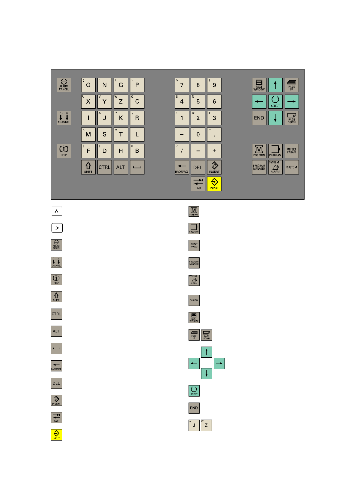
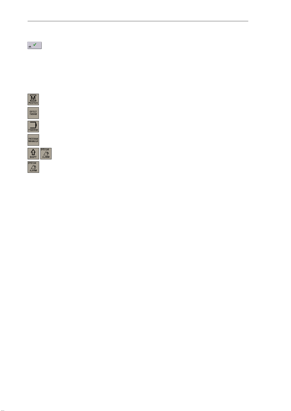
SINUMERIK 802D Key Definition
”Recall” key
ETC key
”Acknowledge alarm” key
without function
Info key
Shift key
Controlkey
Altkey
SPACE
Backspace
Clear key
INSERT key
”Position” operating area key
”Program” operating area key
”Parameter” operating area
”Program Manager” operating area
”Alarm” / ”System” operating areas
(Shift+key)
not assigned
PageUp / PageDown keys
Cursor keys
Selection key / toggle key
Tabulator
ENTER / Input key
SINUMERIK 802D Operation and Programming Milling (BP−F), 08/05 Edition
6FC5 698−2AA10−1BP5
Alphanumeric keys
Double assignment on the Shift level
ix
Page 10
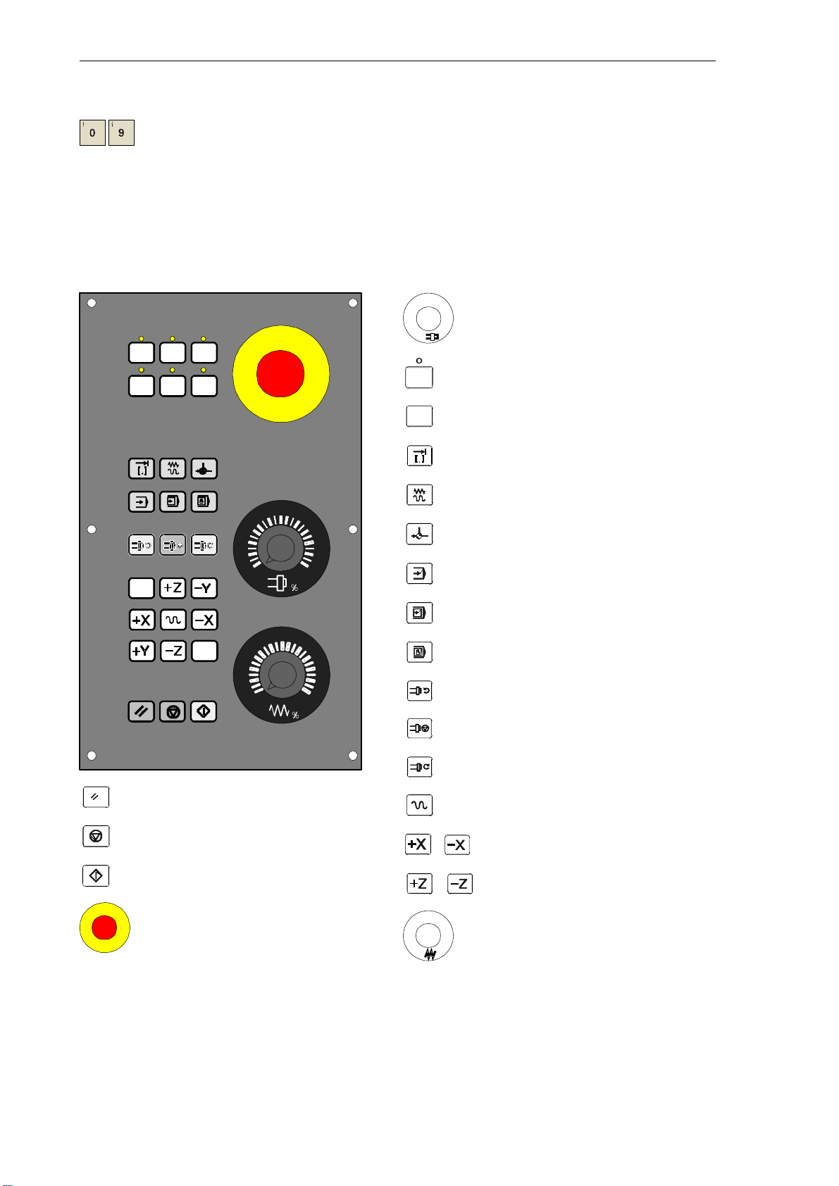
Numeric keys
Double assignment on the Shift level
External Machine Control Panel
%
Spindle override (option)
User−defined key with LED
User−defined key without LED
INCREMENT
80
70
60
90
100
110
120
JOG
REFERENCE POINT
AUTOMATIC
60
70
40
20
10
6
2
0
80
90
100
110
120
SINGLE BLOCK
MANUAL DATA
SPINDLE START LEFT
SPINDLE STOP
SPINDLE START RIGHT
RESET
NC STOP
NC START
EMERGENCY STOP
x
SINUMERIK 802D Operation and Programming Milling (BP−F), 08/05 Edition
X axis
Z axis
%
RAPID TRAVERSE OVERRIDE
Feedrate override
6FC5 698−2AA10−1BP5
Page 11
Introduction
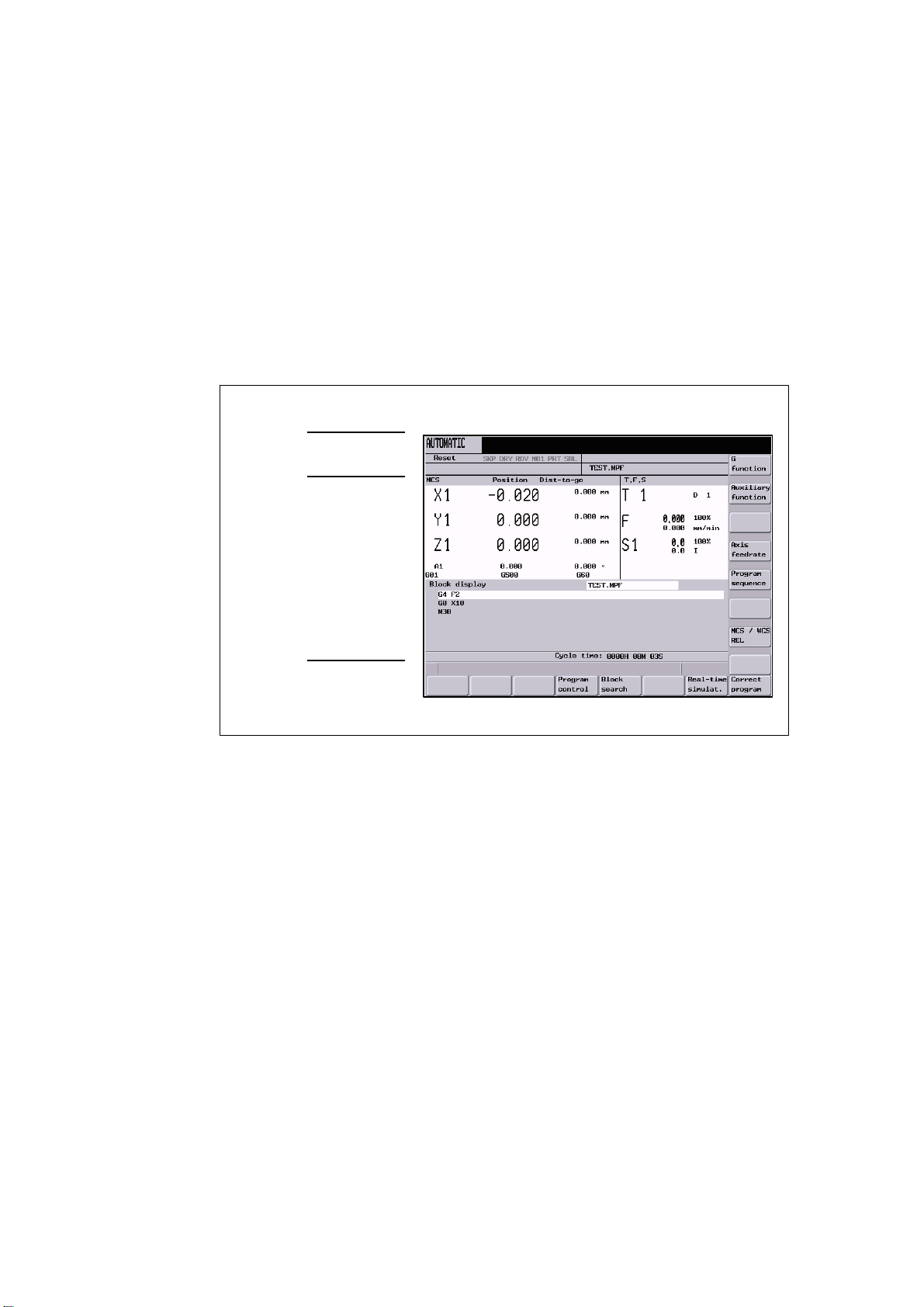
1.1 Screen layout
1
Status area
Applicationarea
Tip
and softkey area
Fig. 1-1 Screen layout
The screen is divided into the following main areas:
S Status area
S Applicationarea
S Tip and softkey area
G
function
SINUMERIK 802D Operation and Programming Milling (BP−F), 08/05 Edition
6FC5 698−2AA10−1BP5
1-11
Page 12
Introduction
MDA
y
System
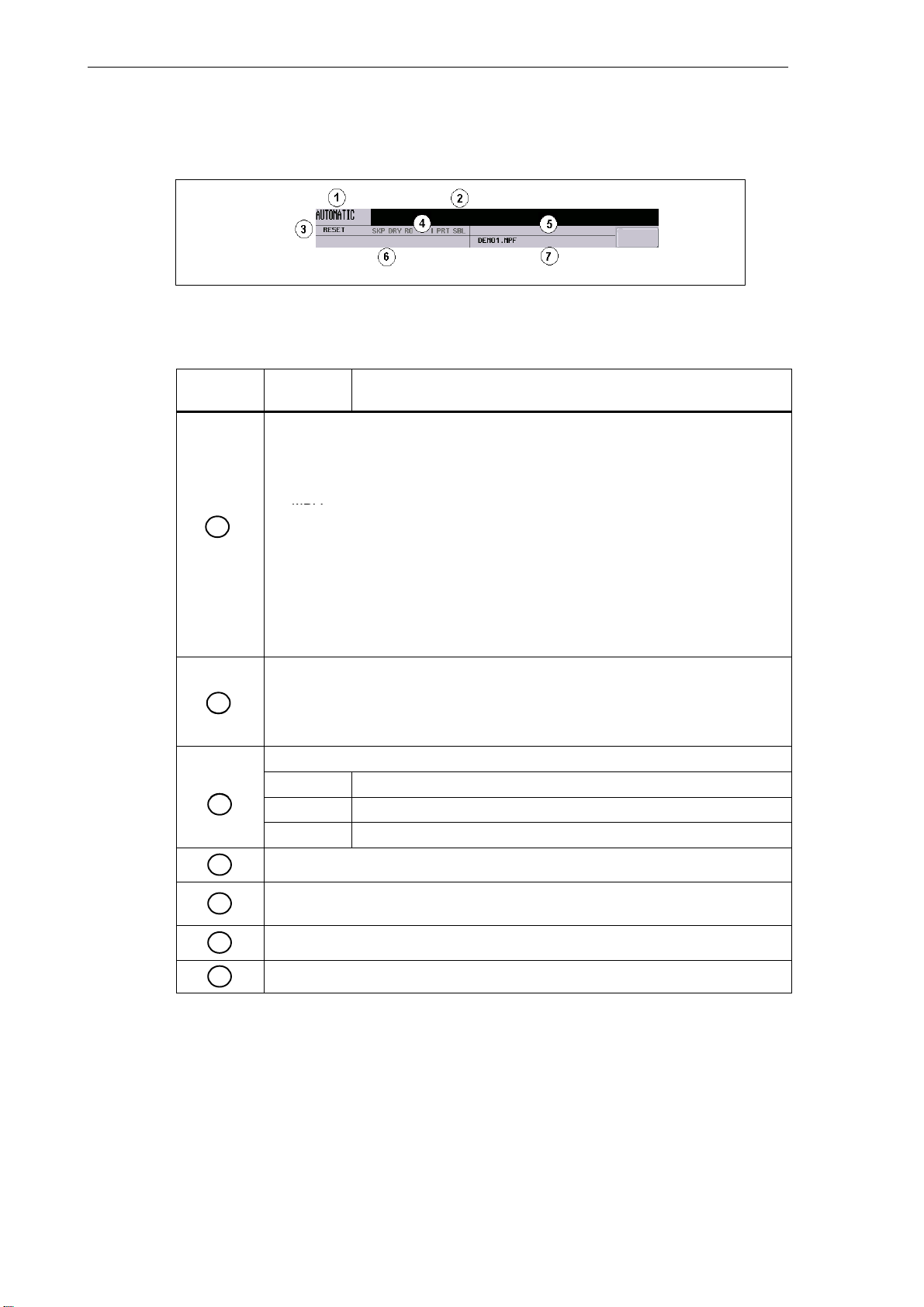
1. Alarm number with alarm text, or
1.1 Screen layout
Status area
Fig. 1-2 Status area
Table 1-1 Explanation of the display elements in the status area
Screen Con-
trol
1
2
3
4
Display Meaning
Active operating area, active mode
Position
JOG; 1 INC, 10 INC, 100 INC, 1000 INC, VAR INC (evaluation by increments in
the JOG mode)
MDA
AUTOMATIC
Offset
Program
Program Manager
stem
S
Alarm
Marked as an ”external language” using G291
Alarm and message line
In addition, the following is displayed:
1. Alarm number with alarm text, or
2. Message text
Program status
RESET Program canceled / default status
RUN Program running
STOP Program stopped
Program controls in the AUTOMATIC mode
1-12
5
6
7
Path N: − NC internal ”drive”
D: − CF card
NC messages
Selected part program (main program)
SINUMERIK 802D Operation and Programming Milling (BP−F), 08/05 Edition
6FC5 698−2AA10−1BP5
Page 13
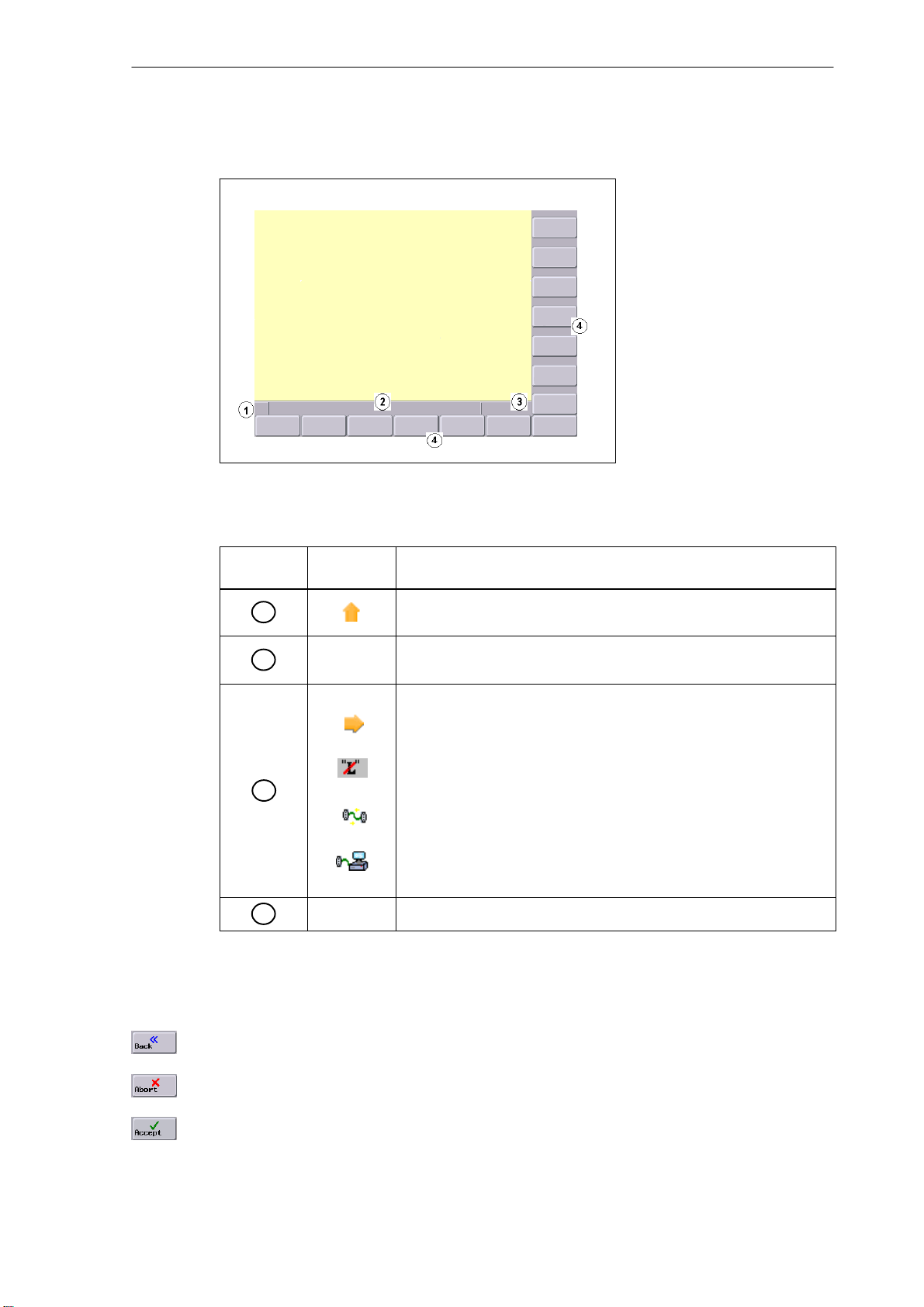
Tip and softkey area
Fig. 1-3 Tip and softkey area
Introduction
1.1 Screen layout
Table 1-2 Explanation of the screen elements in the tip and softkey area
Screen Con-
trol
1
2
3
4
Display Meaning
Recall symbol
Pressing the Recall key lets you return to the next higher menu level.
Tip line
Displays tips for the operator
MMC status information
ETC is possible (Pressing this key displays the horizontal softkey bar
providing further functions.)
Mixed notation active (uppercase/lowercase letters)
Data transfer running
Connection to the PLC programming tool active
Softkey bar vertical and horizontal
Standard softkeys
Use this softkey to quit the screenform.
Use this softkey to cancel the input; the window is closed.
Selecting this softkey will complete your input and start the calculation.
SINUMERIK 802D Operation and Programming Milling (BP−F), 08/05 Edition
6FC5 698−2AA10−1BP5
1-13
Page 14
Introduction
1.2 Operating areas
Selecting this softkey will complete your input and accept the values you have entered.
1.2 Operating areas
The functions of the control system can be carried out in the following operating areas:
Position Machine operation
Offset/Parameters Input of offset values and setting data
Program Creation of part programs
Program Manager Part program directory
System Diagnosis, start−up
Alarm Alarm and message lists
To switch the operating area, use the relevant key (hard key).
Protection levels
The input and modification of vital data in the control system is protected by passwords.
In the menus listed below the input and modification of data depends on the protection level
set:
S Tool offsets
S Work offsets
S Setting data
S RS232 settings
S Program creation / program correction
1-14
SINUMERIK 802D Operation and Programming Milling (BP−F), 08/05 Edition
6FC5 698−2AA10−1BP5
Page 15
1.3 Accessibility options
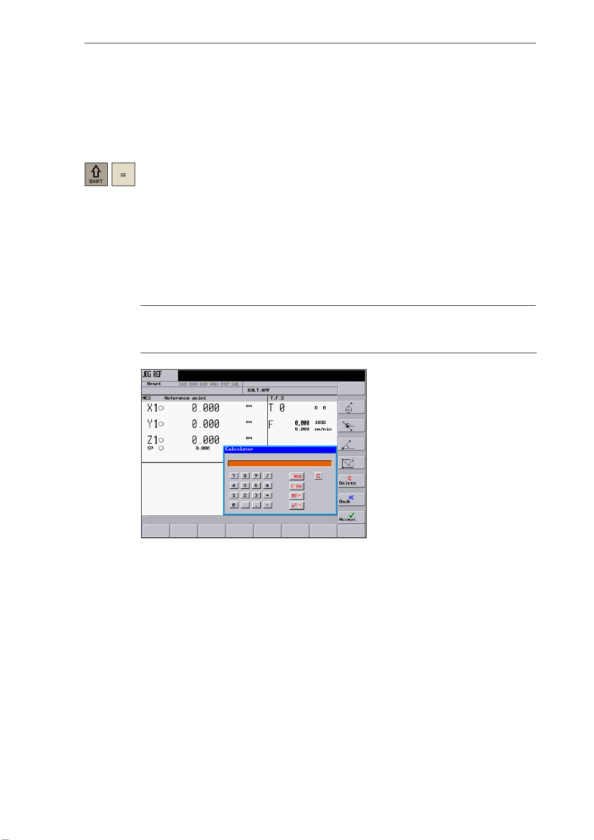
1.3.1 Calculator
The calculator function can be activated from any operating area using ”SHIFT” and ”=”.
To calculate terms, the four basic arithmetic operations can be used, as well as the functions
”sine”, ”cosine”, ”squaring” and ”square root”. A bracket function is provided to calculate
nested terms. The bracket depth is unlimited.
If the input field is already occupied by a value, the function will accept this value into the input
line of the calculator.
When you press the Input key, the result is calculated and displayed in the calculator.
Selecting the Accept softkey enters the result in the input field at the current cursor position of
the part program editor and closes the calculator automatically.
Note
Introduction
1.3 Accessibility options
If an input field is in the editing mode, it is possible to restore the original status using the
”Toggle” key.
Fig. 1-4 Calculator
Characters permitted for input
+, − Basic arithmetic operations
*, /
S Sine function
The X value (in degrees) in front of the input cursor is replaced by the sin(X) value.
O Cosine function
The X value (in degrees) in front of the input cursor is replaced by the cos(X) value.
Q Square function
The X value in front of the input cursor is replaced by the X
SINUMERIK 802D Operation and Programming Milling (BP−F), 08/05 Edition
6FC5 698−2AA10−1BP5
2
value.
1-15
Page 16
Introduction
1.3 Accessibility options
R Square root function
The X value in front of the input cursor is replaced by the √⎮ value.
( ) Bracket function (X+Y)*Z
Calculation examples
100 + (67*3) 100+67*3 −> 301
sin(45_) 45 S −> 0.707107
cos(45_) 45 O −> 0.707107
2
4
√4 4 R −> 2
(34+3*2)*10 (34+3*2)*10 −> 400
To calculate auxiliary points on a contour, the calculator offers the following functions:
Task Input −> Result
4 Q −> 16
Softkeys
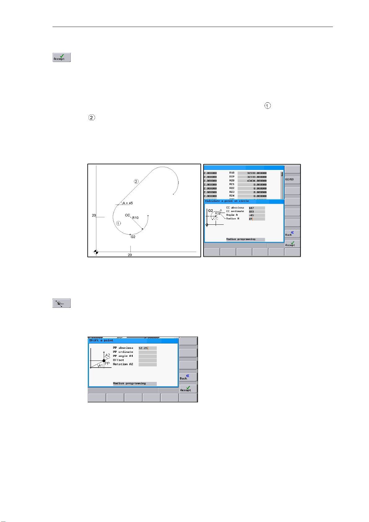
S Calculating the tangential transition between a circle sector and a straight line
S Moving a point in the plane
S Converting polar coordinates to Cartesian coordinates
S Adding the second end point of a straight line/straight line contour section given from an
angular relation
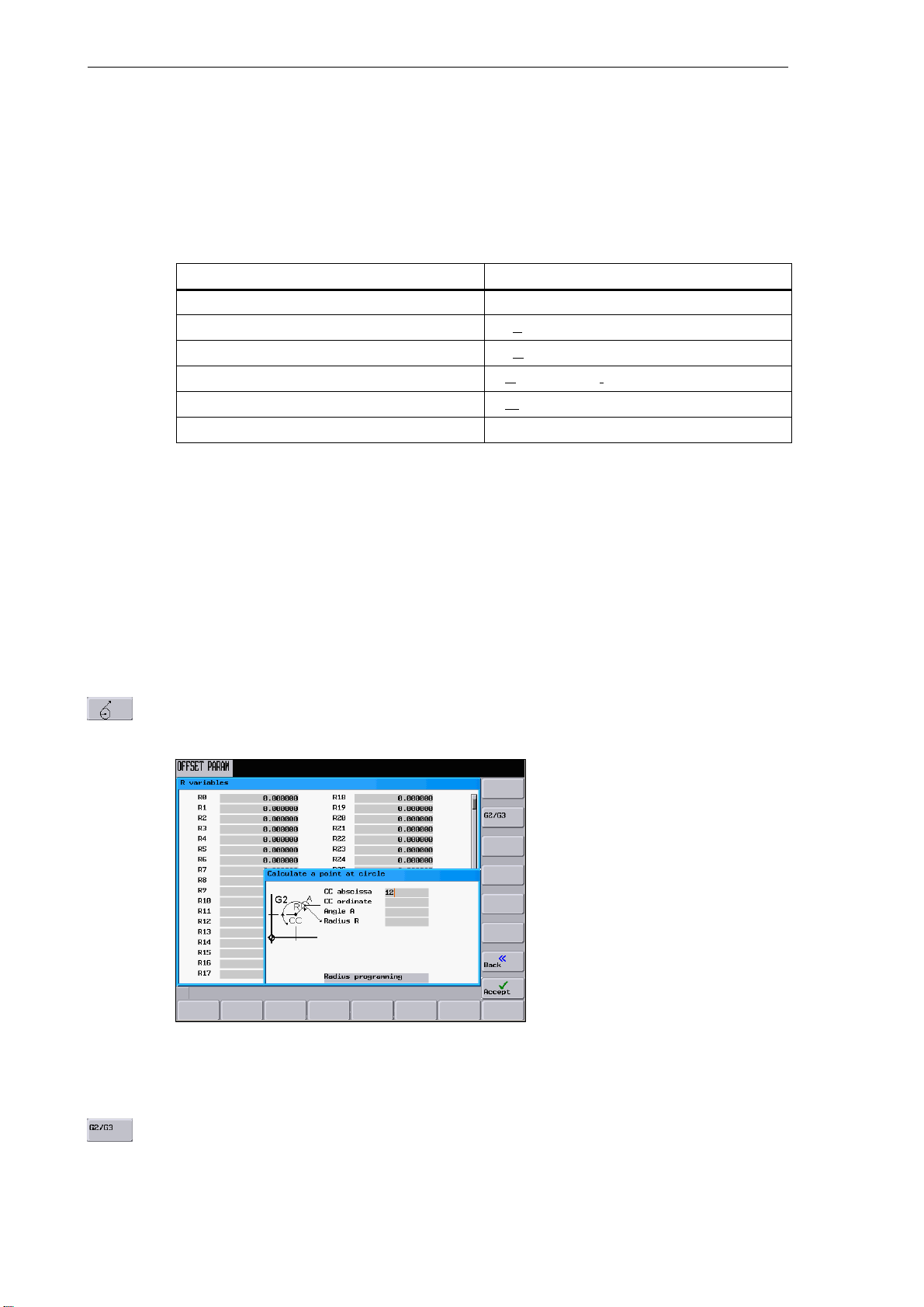
This function is used to calculate a point on a circle. The point results from the angle of the tangent
created, as well as from the radius and the direction of rotation of the circle.
1-16
Fig. 1-5
Enter the circle center, the angle of the tangent and the circle radius.
Use the G2 / G3 softkey to define the direction of rotation of the circle.
SINUMERIK 802D Operation and Programming Milling (BP−F), 08/05 Edition
6FC5 698−2AA10−1BP5
Page 17
Introduction
1.3 Accessibility options
Use this softkey to calculate the abscissa and ordinate values. The abscissa is the first axis of the
plane, and the ordinate is the second axis of the plane. The abscissa value is copied into the input
field from which the calculator function has been called, and the value of the ordinate is copied into
the next following input field. If the function has been called from the part program editor, the coordinates are saved with the axis names of the selected basic plane.
Example: If the G18 plane is active, the abscissa is the Z axis and the ordinate the X axis.
Example: Calculate the intersection point between the circle sector
.
Given: Radius: 10
Circle center: Z 20 X 20
Connection angle of the straight line: 45
°
Direction of rotation: G2
Result: X = 12.928
Y = 27.071
and the straight line
This function calculates the Cartesian coordinates of a point in the plane, which is to be connected
to a point in the plane (PP) on a straight line. For calculation, the distance between the points and
the slope angle (A2) of the new straight line to be created with reference to the slope (A1) of the
given straight line must be known.
Fig. 1-6
SINUMERIK 802D Operation and Programming Milling (BP−F), 08/05 Edition
6FC5 698−2AA10−1BP5
1-17
Page 18
Introduction
1.3 Accessibility options
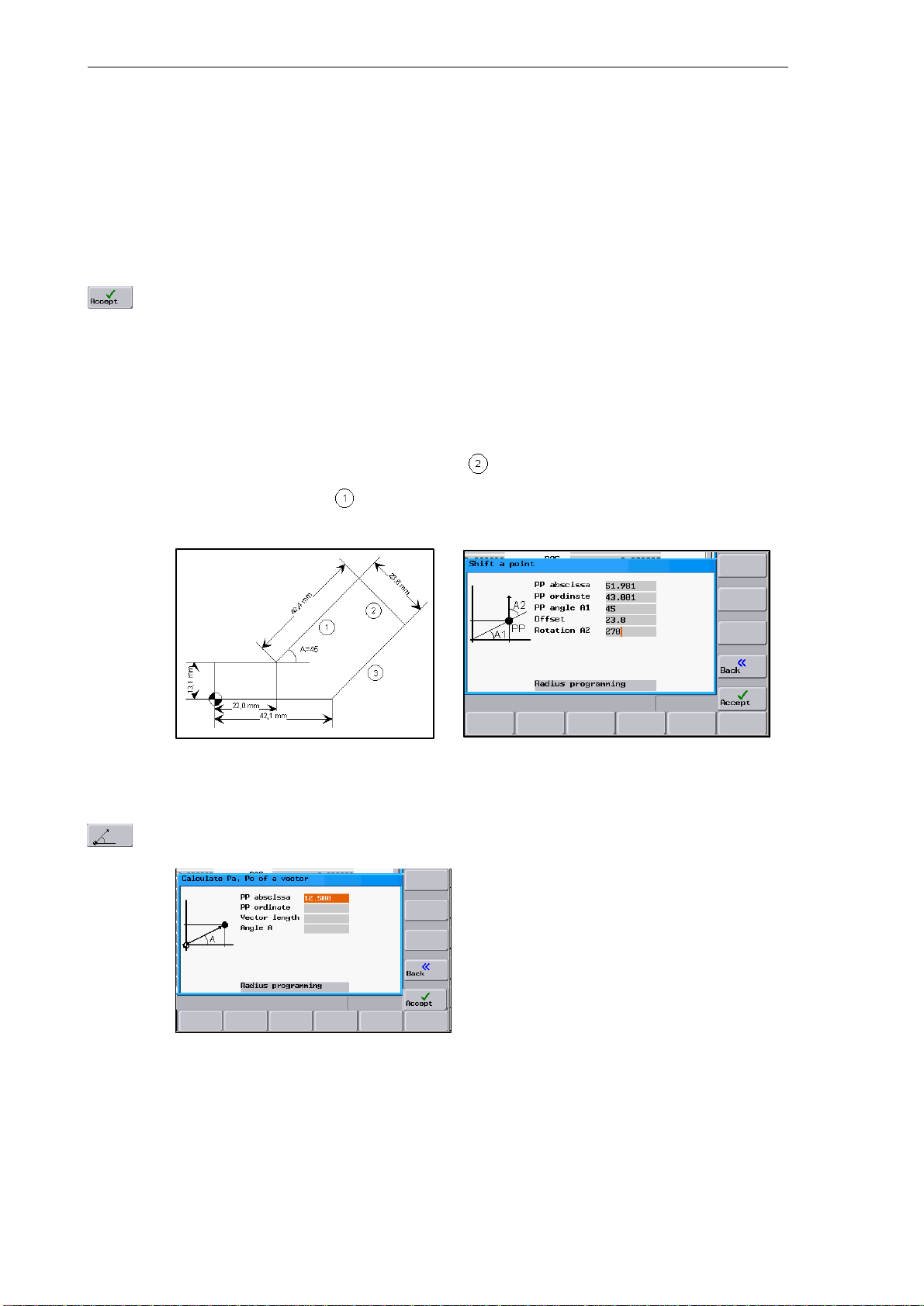
Enter the following coordinates or angles:
S the coordinates of the given point (PP)
S the slope angle of the straight line (A1)
S the distance of the new point with reference to PP(offset)
S the slope angle of the connecting straight line (A2) with reference to A1
Use this softkey to calculate the Cartesian coordinates which are subsequently copied into two input
fields following one after another. The abscissa value is copied into the input field from which the
calculator function has been called, and the value of the ordinate is copied into the next following
input field.
If the function has been called from the part program editor, the coordinates are saved with the axis
names of the selected basic plane.
Example
Calculating the end point of the straight line . The straight line stands vertically on the end
point of the straight line
(Coordinates: X = 51.981, Y = 43.081) (see example: ”Converting
polar coordinates into Cartesian coordinates”). The length of the straight lines is also given.
Result: X = 68.668
Y = 26.393
This function converts the given polar coordinates into Cartesian coordinates.
1-18
Fig. 1-7
Enter the reference point, the vector length and the slope angle.
SINUMERIK 802D Operation and Programming Milling (BP−F), 08/05 Edition
6FC5 698−2AA10−1BP5
Page 19
Introduction
1.3 Accessibility options
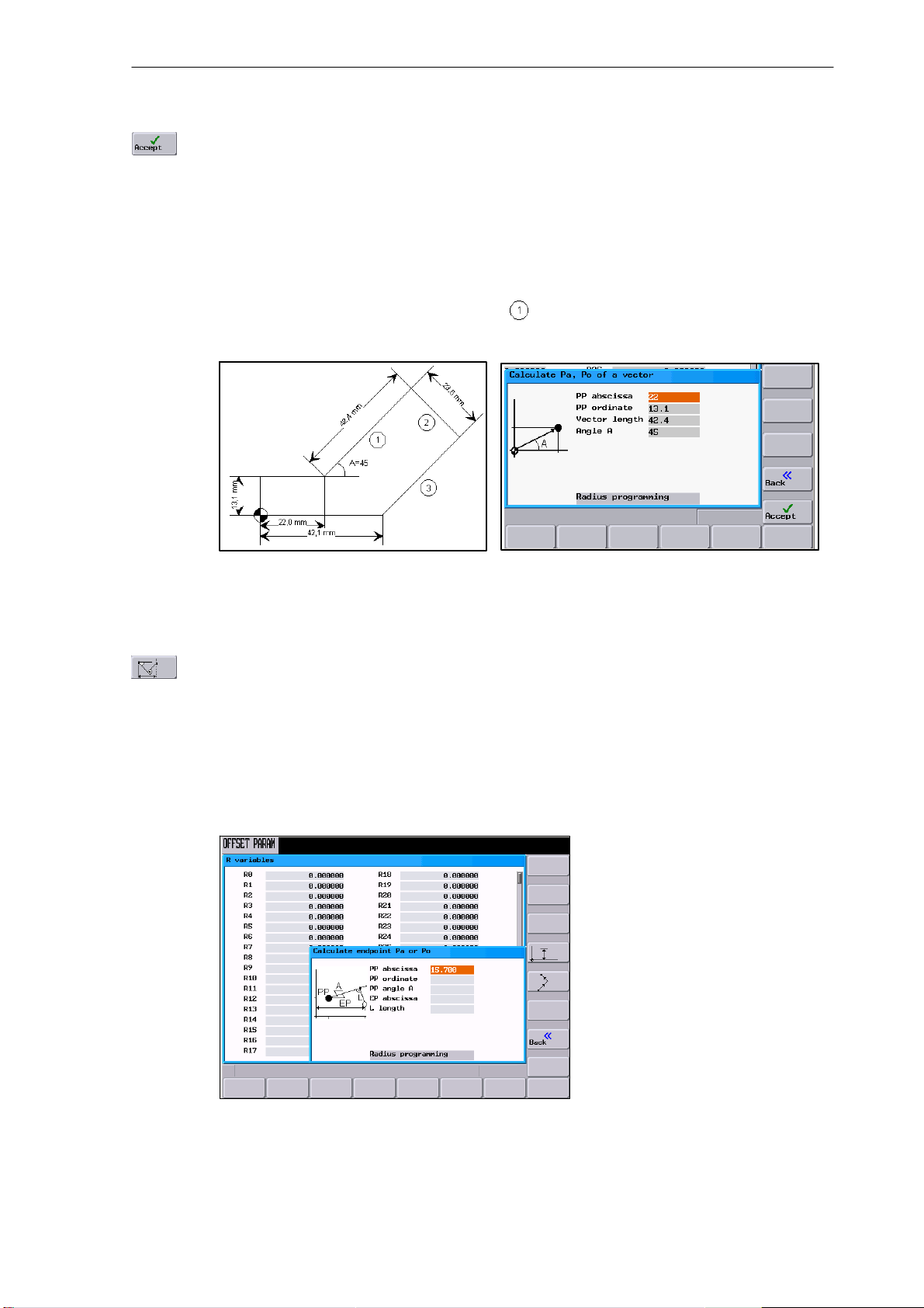
Use this softkey to calculate the Cartesian coordinates which are subsequently copied into two input
fields following one after another. The abscissa value is copied into the input field from which the
calculator function has been called, and the value of the ordinate is copied into the next following
input field.
If the function has been called from the part program editor, the coordinates are saved with the axis
names of the selected basic plane.
Example
Calculating the end point of the straight line . The straight line is determined by the angle
° and its length.
A=45
Result: X = 51.981
Y = 43.081
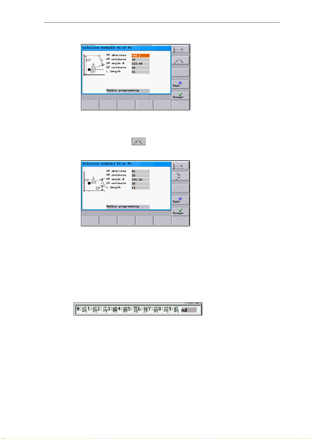
Use this function to calculate the missing end point of the straight line/straight line contour section
whereby the second straight line stands vertically on the first straight line.
The following values of the straight line are known:
Straight line 1:
Starting point and slope angle
Straight line 2:
Length and one end point in the Cartesian coordinate system
Fig. 1-8
SINUMERIK 802D Operation and Programming Milling (BP−F), 08/05 Edition
6FC5 698−2AA10−1BP5
1-19
Page 20
Introduction
1.3 Accessibility options
This function is used to select the given coordinate of the end point.
The ordinate value or the abscissa value is given.
The second straight line is rotated in the CW direction or in the CCW direction by 90 degrees relative to the first straight line.
This function will select the relevant end position.
The missing end point is calculated. The abscissa value is copied into the input field from which the
calculator function has been called, and the value of the ordinate is copied into the next following
input field.
If the function has been called from the part program editor, the coordinates are saved with
the axis names of the selected basic plane.
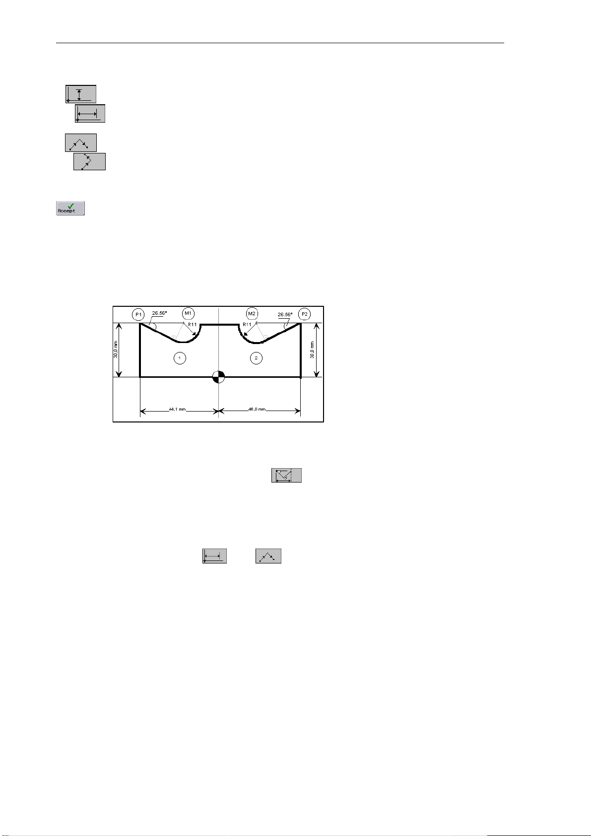
Example
Add the present drawing by the values of the center circle to be able to calculate the points of
intersection between the circle sectors. The missing coordinates of the center points are cal-
culated using the calculator function,
since the radius in the tangential transition
stands vertically on the straight line.
Calculating M1 in section 1:
In this section, the radius stands in the counterclockwise direction turned on the straight
line section.
Use the softkeys
and to select the given configuration.
Enter the coordinates of the pole (PP) P1, the slope angle of the straight line, the given
ordinate value and the circle radius as the length.
1-20
SINUMERIK 802D Operation and Programming Milling (BP−F), 08/05 Edition
6FC5 698−2AA10−1BP5
Page 21
Introduction
1.3 Accessibility options
Result: X = −19.449
Y = 30
Calculating M2 in section 2:
In this section, the radius stands in the clockwise direction turned on the straight line sec-
tion. Use the softkeys
to select the given configuration.
Enter the parameters in the screenform.
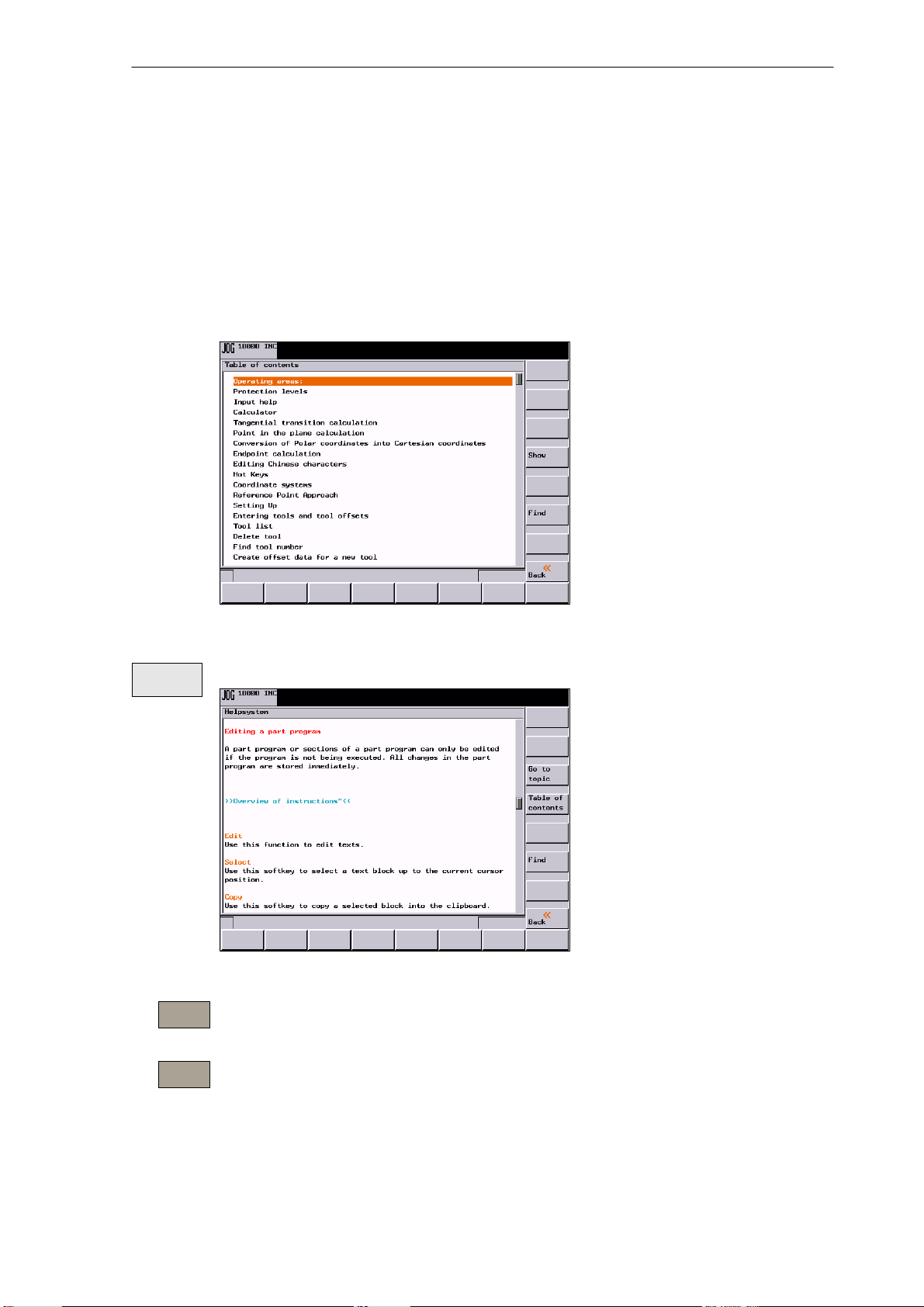
1.3.2 Editing Chinese characters
This function is only available in the Chinese language version.
The control system provides a function for editing Chinese characters in the program editor
and in the PLC alarm text editor. After activation, type the phonetic alphabet of the searched
character in the input field. The editor will then offer various characters for this sound, from
which you can choose the desired one by entering either of the digits 0 to 9.
Result: X = 21.399
Y = 30
Fig. 1-9 Chinese editor
Alt S Is used to turn on / turn off the editor
SINUMERIK 802D Operation and Programming Milling (BP−F), 08/05 Edition
6FC5 698−2AA10−1BP5
1-21
Page 22

Introduction
1.3 Accessibility options
1.3.3 Hotkeys
This operator control can be used to select, copy, cut and delete texts using special key commands. These functions are available both for the part program editor and for input fields.
CTRL C Copy
CTRL B Select
CTRL X Cut
CTRL V Paste
Alt L Switches between uppercase and lowercase letters
Alt H Help system
or Info key
1-22
SINUMERIK 802D Operation and Programming Milling (BP−F), 08/05 Edition
6FC5 698−2AA10−1BP5
Page 23
1.4 The help system
To activate the help system, use the Info key. It offers a brief description for all important operating functions.
In addition, the help offers the following topics:
S Overview of the NC commands with a brief description
S Cycle programming
S Explanation of the drive alarms
Introduction
1.4 The help system
Show
Go to
topic
Back to
topic
Fig. 1-10 Table of contents of the help system
This function opens the selected topic.
Fig. 1-11 Description for a help topic
Use this function to select cross references. A cross reference is marked by the characters
”>>....<<”. This softkey is only unhidden if a cross reference is displayed in the application area.
If you select a cross reference, in addition, the Back to topic softkey is displayed.
This function lets you return to the previous screenform.
SINUMERIK 802D Operation and Programming Milling (BP−F), 08/05 Edition
6FC5 698−2AA10−1BP5
1-23
Page 24

Introduction
1.4 The help system
Find
Use this function to search for a term in the table of contents. Type the term you are looking for and
start the search process.
Help in the ”Program editor” area
The system offers an explanation for each NC instruction. To display the help text directly,
position the cursor after the appropriate instruction and press the Info key. This possibility will
only function if the NC instruction is written using uppercase letters.
1-24
SINUMERIK 802D Operation and Programming Milling (BP−F), 08/05 Edition
6FC5 698−2AA10−1BP5
Page 25
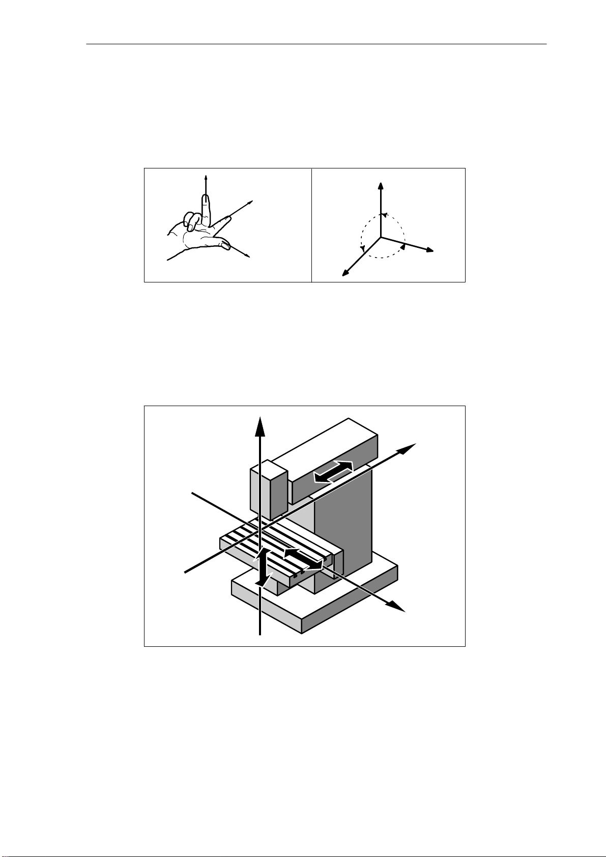
1.5 Coordinate systems
For machine tools, right−handed, right−angled coordinate systems are used.
The movements on the machine are described as a relative movement between tool and
workpiece.
+Z
+Y
+X
Fig. 1-12 Definition of the directions of the axes one to another; right−angled
coordinate system
+Z
90°
90°
Introduction
1.5 Coordinate systems
+Y
90°
+X
Machine coordinate system (MCS)
How the coordinate system is located with reference to the machine, depends on the machine
type concerned. It can be rotated in different positions.
+Z
+Y
+X
Fig. 1-13 Machine coordinates/machine axes using the example of a milling
machine
The origin of the coordinate system is the machine zero.
All axes have zero position. This point only represents a reference point defined by the machine manufacturer. It need not be approachable.
The traversing range of the machine axes can by in the negative range.
SINUMERIK 802D Operation and Programming Milling (BP−F), 08/05 Edition
6FC5 698−2AA10−1BP5
1-25
Page 26
Introduction
1.5 Coordinate systems
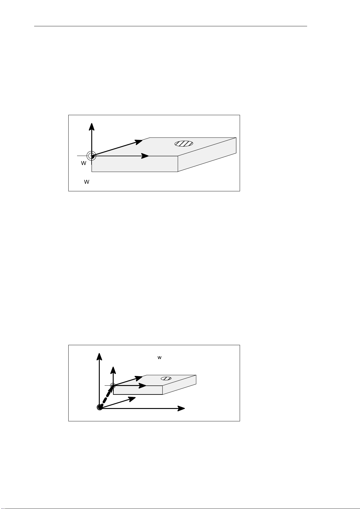
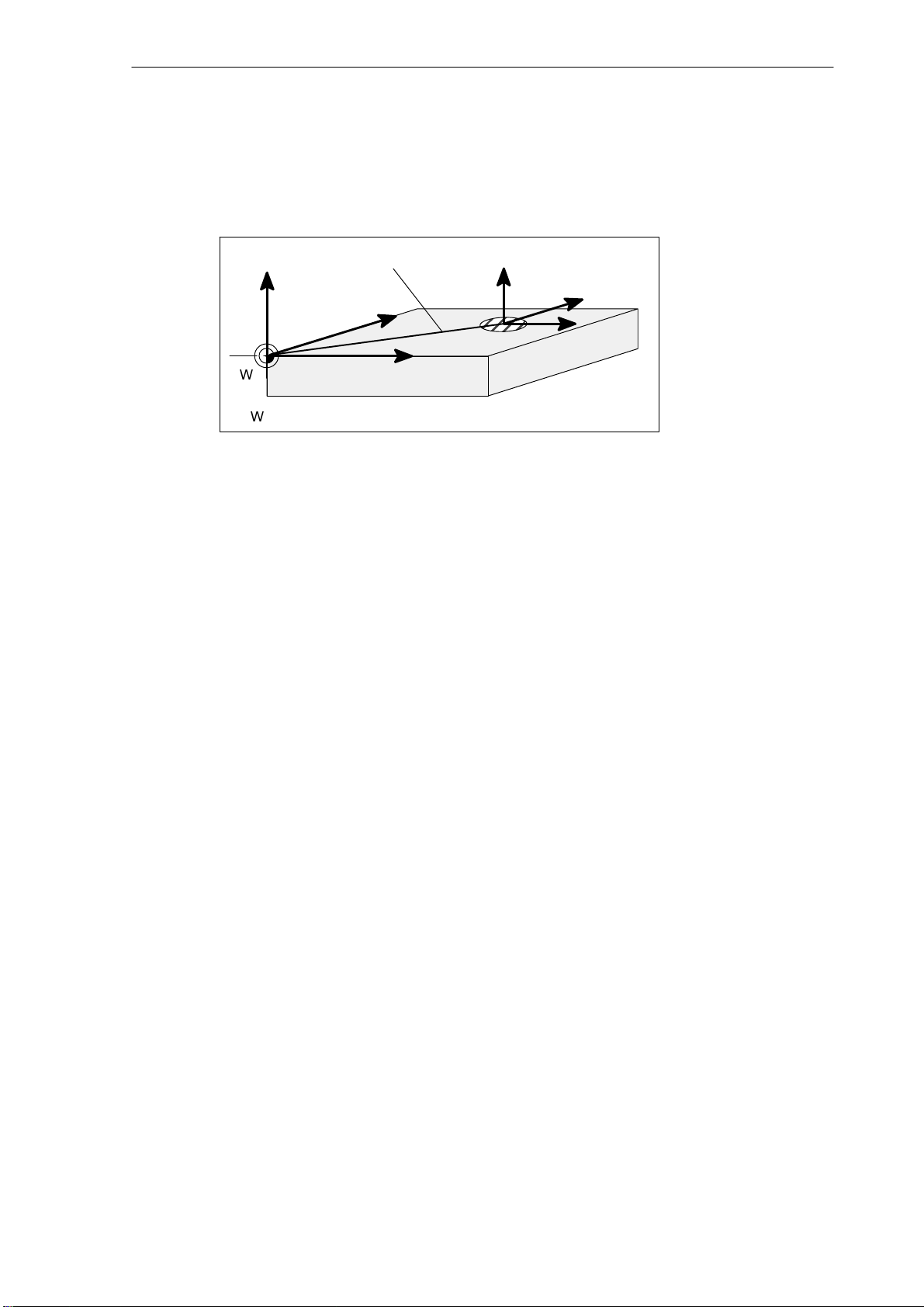
Workpiece coordinate system (WCS)
The coordinate system described above (see Fig. 1-12) is also used to describe the geometry
of a workpiece in the workpiece program.
The workpiece zero can be freely selected by the programmer. The programmer need not to
know the real motion relations on the machine, i.e. he need not to know whether the workpiece or the tool moves. Furthermore, it can be different from axis to axis. The directions are
always defined such if the workpiece would be resting and the tool would move.
Z
Y
W
W - workpiece zero
Fig. 1-14 Workpiece coordinate system
Relative coordinate system
In addition to the machine and workpiece coordinate systems, the control system provides a
relative coordinate system. This coordinate system is used for setting freely selected reference points which have no influence on the active workpiece coordinate system. All axis
movements are displayed relative to these reference points.
Clamping the workpiece
For machining, the workpiece is clamped on the machine. The workpiece must be aligned
such that the axes of the workpiece coordinate system run in parallel with those of the machine. Any resulting offset of the machine zero with reference to the workpiece zero is determined for each axis individually and entered in the relevant data areas intended for the set-
table work offset. In the NC program, this offset is activated, e.g. using a programmed G54
(see also Section ”Workpiece clamping − settable work offset, ...”).
X
1-26
Z
Machine
Z
Workpiece
W - workpiece zero
M − machine zero
Y
e.g.
W
G54
M
Fig. 1-15 Workpiece on the machine
X
Y
Machine
SINUMERIK 802D Operation and Programming Milling (BP−F), 08/05 Edition
X
Machine
6FC5 698−2AA10−1BP5
Page 27
Current workpiece coordinate system
The programmed work offset TRANS can be used to generate an offset with reference to the
workpiece coordinate system resulting in the current workpiece coordinate system (see Section ”Programmable work offset: TRANS”).
Programmable offset
Z
Y
TRANS
Introduction
1.5 Coordinate systems
Z
current
Y
X
W
W - workpiece zero
Fig. 1-16 Coordinates on the workpiece; current workpiece coordinate sy-
stem
X
SINUMERIK 802D Operation and Programming Milling (BP−F), 08/05 Edition
6FC5 698−2AA10−1BP5
1-27
Page 28

Introduction
1.5 Coordinate systems
This sheet has been left empty for your notes
1-28
SINUMERIK 802D Operation and Programming Milling (BP−F), 08/05 Edition
6FC5 698−2AA10−1BP5
Page 29
Turning On and Reference Point Approach
Note
When you turn on the SINUMERIK 802D and the machine, please also observe the Machine Documentation, since turning on and reference point approach are machine−dependent functions.
This documentation assumes an 802D standard machine control panel (MCP). Should you use a
different MCP, the operation may be other than described herein.
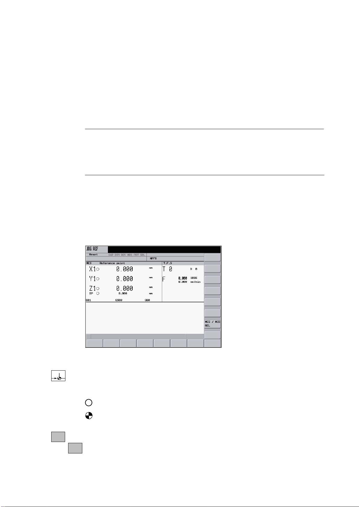
Operating sequence
First, turn on the power supply of CNC and machine. After the control system has booted, you
are in the ”Position” operating area, in the Jog mode.
The ”Reference point approach” window is active.
2
Fig. 2-1 The ”Jog−Ref” start screen
Use the Ref key on the machine control panel to activate ”reference point approach”.
The ”Reference point approach” window (Fig. 2-1) displays whether or not the axes have a
reference point.
Axis must be referenced
Axis has reached its reference point
+X
SINUMERIK 802D Operation and Programming Milling (BP−F), 08/05 Edition
6FC5 698−2AA10−1BP5
Press a direction key.
...
-Z
2-29
Page 30

Turning On and Reference Point Approach
If you select the wrong approach direction, no motion will be carried out.
Approach the reference points for each axis one after the other.
Quit the function by switching the mode (MDA, AUTOMATIC or Jog).
Note
”Reference point approach” is only possible in the Jog mode.
2-30
SINUMERIK 802D Operation and Programming Milling (BP−F), 08/05 Edition
6FC5 698−2AA10−1BP5
Page 31

Setting Up
Preliminary remarks
Before you can work with the CNC, set up the machine, the tools, etc. on the CNC as follows:
S Enter the tools and the tool offsets
S Enter/modify the work offset
S Enter the setting data
3.1 Entering tools and tool offsets
Functionality
The tool offsets consist of several data describing the geometry, the wear and the tool type.
Depending on the tool type, each tool is assigned a defined number of parameters. Tools are
identified by a number (T number).
See also Section 8.6 ”Tool and tool compensation”
3
Operating sequences
Use this softkey to open the ”Tool offset data” window which contains a list of the tools created. Use
the cursor keys and the PageUp / PageDown keys to navigate in this list.
Tool
List
Fig. 3-1
SINUMERIK 802D Operation and Programming Milling (BP−F), 08/05 Edition
6FC5 698−2AA10−1BP5
3-31
Page 32

Setting Up
3.1 Entering tools and tool offsets
Enter the offsets by positioning the
S cursor bar on the input field to be changed,
S enter the value(s)
and either press Input or use a cursor key to confirm.
Softkeys
Tool
Measur.
Measure
manually
Measure
auto
Calibrate
probe
Delete
tool
Extend
For special tools, the
Extend
softkey function is provided which offers a complete parameter
list which can be filled out.
Use this softkey to determine the tool offset data (only effective in the JOG mode!)
Use this softkey to determine the tool compensation data manually.
Use this softkey to determine the tool offset data semi−automatically (only applies in conjunction
with a sensing probe).
Use this softkey to calibrate the sensing probe.
Selecting this softkey will delete the tool offset data of all edges of the tool.
Use this function to display all parameters of a tool.
Edges
3-32
D >>
<< D
Fig. 3-2 Input screen for special tools
For the meanings of the parameters, please refer to the Section ”Programming”.
Opens a lower−level menu bar offering all functions required to create and display further edges.
Use this softkey to select the next higher edge number.
Use this softkey to select the next lower edge number.
SINUMERIK 802D Operation and Programming Milling (BP−F), 08/05 Edition
6FC5 698−2AA10−1BP5
Page 33

Setting Up
3.1 Entering tools and tool offsets
New
tool edge
Reset
edge
Change
type
Find
Use this softkey to create a new edge.
Use this softkey to reset all compensation values of the edge to zero.
This function is intended to change the tool type. select the tool type using the appropriate softkey.
Find tool number
Type the number of the tool you are looking for and select the OK softkey to start searching. If the
tool you are looking for exists, the cursor is positioned on the appropriate line.
New
tool
Use this softkey to create tool offset data for a new tool.
3.1.1 Use this softkey to create a new tool.
Operating sequence
New
tool
This function offers another two softkey functions to select the tool type. After selecting the tool type,
type the desired tool number in the input field.
Fig. 3-3 The ”New tool” window Input of the tool number
Select OK to confirm your input. A data record loaded with zero will be included in the tool list.
OK
3.1.2 Determining the tool offsets (manually)
Functionality
This function can be used to determine the unknown geometry of a tool T.
SINUMERIK 802D Operation and Programming Milling (BP−F), 08/05 Edition
6FC5 698−2AA10−1BP5
3-33
Page 34

Setting Up
3.1 Entering tools and tool offsets
Prerequisite
The relevant tool is loaded. In the JOG mode, you will approach the edge of the tool to a ma-
chine point whose machine coordinate values are known. This can be a workpiece with a
known position.
Procedure
Enter the reference point in the appropriate field X0, Y0 or Z0.
Please observe: For milling tools, length 1 and the radius must be determined, and for drilling
tools only length 1.
By using the actual position of point F (machine coordinate) and the reference point, the con-
trol system can calculate the offset value assigned to length 1 or the radius for the selected
axis.
Note: You can also use a zero already determined (e.g value of G54). In this case, use the
edge of the tool to approach the workpiece zero point. If the edge is positioned directly at
workpiece zero, the reference point is zero.
F − toolholder reference point
M − machine zero
W - workpiece zero
Fig. 3-4 Determination of the length offset using the example of a drill: Length 1 / Z axis
Operating sequence
Tool
Measur.
Select this softkey. The Measure tool window is opened. You will automatically get to the ”Position”
operating area.
Z
Machine
Workpiece
M
F
Intermediate position
W
Length 1=?
Known machine
coordinate value Z
Offset
Gxx, e.g. G54
Zactual position
X
Machine
3-34
SINUMERIK 802D Operation and Programming Milling (BP−F), 08/05 Edition
6FC5 698−2AA10−1BP5
Page 35

Fig. 3-5 Selecting manual or semiautomatic measuring
Setting Up
3.1 Entering tools and tool offsets
Measure
manually
The Measure tool window is opened.
Fig. 3-6 ”Offset values” window; measuring the length and the tool diameter
S Enter the reference point in the field X0, Y0 or Z0. This can be either the current machine
coordinate (absolute) or a value from the work offsets (base, G54 − G59). If any other val-
ues are used, the offset value will refer to the specified position.
S After selecting the Set length or Set diameter softkey, the control system will calculate
the searched geometry length 1 or the diameter according to the preselected axis. The
offset value determined will be stored.
S If a spacer is inserted between the tool and the workpiece, its thickness can be entered in
the ”Clearance” field.
SINUMERIK 802D Operation and Programming Milling (BP−F), 08/05 Edition
6FC5 698−2AA10−1BP5
3-35
Page 36

Setting Up
3.1 Entering tools and tool offsets
3.1.3 Determining tool compensations using a probe
Operating sequence
Tool
Measur.
Measure
auto
Use this softkey to open the Measure tool window.
After the screenform has appeared, the input fields are loaded with the tool currently working,
and the plane in which the measurements are to be performed are displayed.
This setting can be changed in the Probe data settings screenform (Section 3.1.4).
Note
To create the measuring program, the ”Safety clearance” parameters from the ”Settings” screenform
and the feedrate from the ”Probe data” screenform are used.
If several axes are moved simultaneously, no probe position data can be calculated.
Measuring the tool length
3-36
Fig. 3-7 The ”Offset values” window; measuring the tool length
Use the feed axis to traverse to the probe.
After the ”Probe triggered” has
measuring process is completed. A dial gauge
appeared, release the traversing key and wait until the
symbolizing the active measuring process
is displayed on the animated screen during the automatic measurement.
SINUMERIK 802D Operation and Programming Milling (BP−F), 08/05 Edition
6FC5 698−2AA10−1BP5
Page 37

Measuring the tool diameter
The diameter can only be determined with the spindle rotating. To this end, enter the speed
and the direction of rotation of the spindle in the Sensing probe data screen.
Fig. 3-8 The ”Offset values” window; measuring the diameter
Setting Up
3.1 Entering tools and tool offsets
Use any axis from the plane to traverse to the probe. Depending on the axis selected, traverse
either to point P1 or P3, or P2 or P4.
After the ”Probe triggered” has
measuring process is completed. A dial gauge
is displayed on the animated screen during the automatic measurement.
Warning
!
The spindle will rotate at the speed defined in the probe data!
3.1.4 Probe settings
Settings
Data
probe
The screenform below is used to store the coordinates of the probe and to set the following
parameters for the automatic measuring process:
appeared, release the traversing key and wait until the
symbolizing the active measuring process
S Plane of the probe
S Axis feedrate
S Speed and direction of rotation of the spindle
The direction of rotation of the spindle must be opposite to the cutting direction of the cutter.
SINUMERIK 802D Operation and Programming Milling (BP−F), 08/05 Edition
6FC5 698−2AA10−1BP5
3-37
Page 38

Setting Up
3.1 Entering tools and tool offsets
All position values refer to the machine coordinate system.
Fig. 3-9 The ”Probe data” interactive screenform
Table 3-1 Meaning of the input fields
abs. position P5 Absolute position of the probe in the Z− direction
Center point: X
Center point: Y
Diameter Diameter of the probe disk (after calibration, the calculated diam-
Thickness Thickness of the probe disk
Calibrating the probe
Calibrate
probe
The calibration of the probe can be carried out either in the Settings menu or in the Tool measure
menu.
Parameter
Meaning
Calculated center point of the probe (machine coordinates)
eter is displayed)
3-38
Fig. 3-10 Calibrating the probe (length) (diameter)
SINUMERIK 802D Operation and Programming Milling (BP−F), 08/05 Edition
6FC5 698−2AA10−1BP5
Page 39

Setting Up
3.1 Entering tools and tool offsets
After the screenform has appeared, an animation signaling the step to be executed is displayed next to the current positions of the probe. This point must be approached with the appropriate axis. If the probe is triggered, the control system will take over the measuring process by switching to the AUTOMATIC mode, activating the measuring program and starting it
automatically. The operator will see an axis movement in the opposite direction for a short
time.
During the automatic measurement, a dial appears
symbolizing that the NC is active.
The positions delivered by the measuring program serve to calculate the real probe position.
Note
To create the measuring program, the parameters ”Safety clearance” from the ”Settings” screenform
and feedrate from the ”Probe data” screenform are used.
SINUMERIK 802D Operation and Programming Milling (BP−F), 08/05 Edition
6FC5 698−2AA10−1BP5
3-39
Page 40

Setting Up
3.2 Tool monitoring
3.2 Tool monitoring
Toollife
Each monitoring type is represented in 4 columns.
S Setpoint
S Prewarning limit
S Residual value
S active
Use the checkbox element in the 4th column to enable / disable the monitoring type.
Fig. 3-11 Tool monitoring
Reset
monitor
Symbols in the T column provide information on the tool status.
Prewarning limit reached
Tool disabled
Tool is monitored
Use this softkey to reset the monitoring values of the selected tool.
3-40
SINUMERIK 802D Operation and Programming Milling (BP−F), 08/05 Edition
6FC5 698−2AA10−1BP5
Page 41

Fig. 3-12
Setting Up
3.2 Tool monitoring
After
enable
Use this softkey to change the enable of the selected tool.
SINUMERIK 802D Operation and Programming Milling (BP−F), 08/05 Edition
6FC5 698−2AA10−1BP5
3-41
Page 42

Setting Up
3.3 Entering/modifying a work offset
3.3 Entering/modifying a work offset
Functionality
After the reference point approach, the actual−value memory and thus also the actual−value
display are referred to the machine zero. A machining program, however, is always referred to
the workpiece zero. This offset must be entered as the work offset.
Operating sequences
Use Offset Parameter and Work Offset to select the work offset.
An overview of all settable work offsets will appear on the screen. The screenform additionally
Work
offset
contains the values of the programmed work offset, of the active scaling factors, the status
display and the total of all active work offsets.
Change
activated
Fig. 3-13 The ”Work offset” window
Position the cursor bar on the input field to be changed
and enter the value(s). Either move the cursor a press the Input key to accept the values from the
input fields into the work offsets.
The compensation values of the cutting edge come into effect immediately.
3-42
SINUMERIK 802D Operation and Programming Milling (BP−F), 08/05 Edition
6FC5 698−2AA10−1BP5
Page 43

3.3.1 Determining the work offset
Prerequisite
You have select the window with the relevant work offset (e.g. G54) and the axis you want to
determine for the offset.
Setting Up
3.3 Entering/modifying a work offset
Procedure
Measure
workpiece
Fig. 3-14 Determining the work offset
Select the ”Measure workpiece” softkey. The control system will switch to the ”Position” operating
area and will open the dialog box for measuring the work offsets. The selected axis will appear as a
softkey with a black background.
Then scratch the workpiece with the tool.
If scratching is not possible or if the desired point cannot be reached with the tool (for exam-
ple, when using a spacer), the clearance between the tool and the workpiece surface must be
entered in the ”Clearance” field.
To determine the offset, the direction of movement of the tool must be taken into account for
the active tool. If no tool is active, the ”Radius” field is hidden.
Fig. 3-15 The Determine work offset in X” screenform
The ”Determine work offset in Y” screenform
SINUMERIK 802D Operation and Programming Milling (BP−F), 08/05 Edition
6FC5 698−2AA10−1BP5
3-43
Page 44

Setting Up
3.3 Entering/modifying a work offset
Fig. 3-16 The Determine work offset in Zscreen
Set work
offset
Selecting this softkey will calculate the offset and display the result in the ”Offset” field.
3-44
SINUMERIK 802D Operation and Programming Milling (BP−F), 08/05 Edition
6FC5 698−2AA10−1BP5
Page 45

Setting Up
3.4 Programming setting data - ”Parameter” operating area
3.4 Programming setting data - ”Parameter” operating area
Functionality
The setting data are used to define the settings for the operating states. These can be
changed as necessary.
Operating sequences
Select Setting data using the Offset/Param and the Setting data keys.
Setting
data
The Setting data softkey branches to another menu level where various control options can
be set.
Fig. 3-17 The Setting datastart screen
JOG feedrate
Feedrate in the Jog mode
If the feedrate value is zero, the control system will use the value stored in the machine
data.
Spindle
Spindle speed
Minimum / maximum
A limitation of the spindle speed in the ”Max.” (G26) / ”Min.” (G25) fields can only be performed within the limit values defined in the machine data.
Programmed (limitation)
Programmable upper speed limitation (LIMS) at constant cutting rate (G96).
Dry run feed (DRY)
The feedrate which can be entered here will be used instead of the programmed feedrate
in the AUTOMATIC mode if the ”Dry run feed” function is selected.
SINUMERIK 802D Operation and Programming Milling (BP−F), 08/05 Edition
6FC5 698−2AA10−1BP5
3-45
Page 46

Setting Up
3.4 Programming setting data - ”Parameter” operating area
Start angle for thread cutting (SF)
For thread cutting, a start position for the spindle is displayed as the start angle. If the
thread cutting operation is repeated, a multiple thread can be cut by modifying the angle.
Position the cursor bar on the input field you want to change and enter the value(s).
Either press the Input key or move the cursor to confirm.
Softkeys
Work area
limit.
The working area limitation is active with geometry and additional axes. Enter the values for the
work area limitation. Selecting the Set Active softkey will activate / deactivate the values for the axis
highlighted by the cursor.
Time
counter
Fig. 3-18
Timers Counters
Fig. 3-19
3-46
SINUMERIK 802D Operation and Programming Milling (BP−F), 08/05 Edition
6FC5 698−2AA10−1BP5
Page 47

Setting Up
3.4 Programming setting data - ”Parameter” operating area
Meaning:
S Parts required: Number of workpieces required ( require number of workpieces )
S Parts total: Number of workpieces produced in total ( actual total )
S Part count: This counter registers the number of all workpieces produced since the starting
time.
S Run time: Total runtime of NC programs in the AUTOMATIC mode(in seconds)
In the AUTOMATIC mode, the runtimes of all programs between NC START and end of
program / RESET are summed up. The timer is zeroed with each power−up of the control
system. Runtime of the selected NC program (in seconds)
S Cycle time: Tool action time (in seconds)
The runtime between NC START and end of program / RESET is measured in the selected NC program. The timer is reset with starting a new NC program.
S Cutting time
The runtime of the path axes is measured in all NC programs between NC START and end
of program / RESET without rapid traverse active and with the tool active. The measurement is interrupted when a dwell time is active.
Misc
The timer is automatically reset to zero in the case of a ”Control power−up with default values”.
Use this function to display all setting data for the control system in the form of a list. The data are
divided into
S general
S axis−specific and
S channel setting data.
Fig. 3-20
SINUMERIK 802D Operation and Programming Milling (BP−F), 08/05 Edition
6FC5 698−2AA10−1BP5
3-47
Page 48

Setting Up
3.5 R parameters − ”Offset/Parameter”operating area
3.5 R parameters − ”Offset/Parameter”operating area
Functionality
The R parameters start screen displays all R parameters existing in the control system in the form of a list (see also Section 8.9 ”R parameters”). These can be changed as necessary.
Fig. 3-21 The ”R parameters” window
Operating sequence
Use the variable and the R variablesoftkeys
R vari−
able
to position the cursor bar on the input field you want to change and enter the values.
Either press the Input key or move the cursor to confirm.
3-48
SINUMERIK 802D Operation and Programming Milling (BP−F), 08/05 Edition
6FC5 698−2AA10−1BP5
Page 49

Manually Controlled Mode
Preliminary remark
The manually controlled mode is possible in the Jog and MDA modes.
4
Set
base
x=0
y=0
z=0
Add.
axes
Set rel
Delete
base W0
All
to zero
Back <<
Measure
workpiece
Work
offset
X
Y
Z
Set work
offset
Back <<
Tool
measure
Measure
manual
Measure
auto
Calibrate
probe
Back <<
Fig. 4-1 Menu tree for the JOG mode, ”Position” operating area
Set
base
x=0
Face
Settings
Data
probe
Switch
mm>inch.
Back <<
Settings
y=o
z=0
Add.
axes
Set rel
Delete
base Z0
All
to zero
Back <<
Fig. 4-2 Menu tree for the MDA mode, ”Machine” operating area
SINUMERIK 802D Operation and Programming Milling (BP−F), 08/05 Edition
6FC5 698−2AA10−1BP5
Abort
OK
4-49
Page 50

Manually Controlled Mode
4.1 JOG mode - ”Position” operating area
4.1 JOG mode - ”Position” operating area
Operating sequences
Use the Jog key on the machine control panel to select the Jog mode.
+X
-Z
...
To traverse the axes, press the appropriate key of the X, Y or Z axis.
The axes will traverse continuously at the velocity stored in the setting data until the key is
released. If the value of the setting data is zero, the value stored in the machine data is used.
If necessary set the velocity using the override switch.
%
If you press additionally the Rapid traverse override key, the selected axis will be traversed at
rapid traverse speed until both keys are released.
In the Jog mode, you can traverse the axes by adjustable increments using the same operating
sequence. The set number of increments is visualized in the display area. To deselect the Jog
mode, press Jog once more.
The Jog start screen displays the position, feedrate and spindle values, as well as the current
tool.
4-50
Fig. 4-3 The ”Jog” start screen
SINUMERIK 802D Operation and Programming Milling (BP−F), 08/05 Edition
6FC5 698−2AA10−1BP5
Page 51

Parameters
Manually Controlled Mode
4.1 JOG mode - ”Position” operating area
Table 4-1 Description of the parameters in the JOG start screen
Parameter
MCS
X
Y
Z
+X
....
−Z
Position
mm
REPOS offset If the axes are traversed in the ”Program interrupted” condition in the Jog mode, the distance
G function Displays important G functions
Spindle S
r.p.m.
Feed F
mm/min
Tool Displays the currently active tool with the current edge number
Displays the address of the axes existing in the machine coordinate system (MCS)
If you traverse an axis in the positive (+) or negative (-) direction, a plus or minus sign will appear in the relevant field.
If the axis is already in the required position, no sign is displayed.
These fields display the current position of the axes in the MCS or WCS.
traversed by each axis is displayed referred to the interruption point.
Displays the actual value and the setpoint of the spindle speed
Displays the path feedrate actual value and setpoint
Explanation
Note
If a second spindle is integrated into the system, the workspindle will be displayed using a smaller
font. The window will always display the data of only one spindle.
Softkeys
Set
base
The control system displays the spindle data according to the following aspects
:
The master spindle is displayed:
− in the idle condition;
− when starting the spindle;
− if both spindles are active.
The workspindle is displayed:
− when starting the workspindle.
The power bar applies to the spindle currently active.
This softkey is used to set the base work offset or a temporary reference point in the relative coordinate system. After opening, this function can be used to set the base work offset.
SINUMERIK 802D Operation and Programming Milling (BP−F), 08/05 Edition
6FC5 698−2AA10−1BP5
4-51
Page 52

Manually Controlled Mode
4.1 JOG mode - ”Position” operating area
The following subfunctions are provided:
S Direct input of the desired axis position
In the input window, position the input cursor on the desired axis; thereafter, enter the new
position. Then, press Input or move the cursor to confirm your input.
S Setting of all axes to zero
The X=Y=Z=0 softkey function overwrites the current position of the appropriate axis with
zero.
S Setting of individual axes to zero
Use the X=0 Y=0 or Z=0 softkey to overwrite the current position with zero.
Any additional axes must only be set to zero if the X, YX and Z geometry axes required for
milling have been configured.
Use the Set rel softkey to switch the display to the relative coordinate system. Any subsequent inputs will change the reference point in this coordinate system.
Note
A changed base work offset acts independently of any other work offsets.
Measure
workpiece
Tool
measure
Settings
Use this softkey to determine the work offset (cf. Chapter 3)
Use this softkey to measure the tool offsets (cf. Chapter 3)
The interactive screenform shown below is intended to set the retraction plane, the safety clearance
and the direction of rotation of the spindle for automatically generated part programs in the MDA
mode (see Section4.2.1). Furthermore, the values for the JOG feedrate and the variable size of increments can be set.
4-52
Fig. 4-4
SINUMERIK 802D Operation and Programming Milling (BP−F), 08/05 Edition
6FC5 698−2AA10−1BP5
Page 53

Manually Controlled Mode
4.1 JOG mode - ”Position” operating area
Retract plane: The Face function retracts the tool to the specified position (Z position) after
the function has been executed.
Safety distance: Safety clearance to the workpiece surface
This value defines the minimum distance between the workpiece surface and the workpiece. It
is used by the ”Face” and ”Automatic tool gauging” functions.
JOG feedrate: Feedrate value in the JOG mode
Dir. of rot.: Direction of rotation of the spindle for automatically generated programs in the
JOG and MDA modes.
Switch
mm > inch
Use this softkey to switch between the metric and the inch system.
4.1.1 Assigning handwheels
Operating sequence
Hand
wheel
Use this softkey to display the handwheel window in the Jog mode.
After the window has been opened, all axis identifiers are displayed in the ”Axis” column,
which simultaneously appear in the softkey bar. Depending on the number of handwheels
connected, you can switch from handwheel 1 to handwheel 2 or 3.
Select the desired handwheel using the cursor. Thereafter, select the relevant axis softkey for the
required axis for assignment or deselection.
The .
Fig. 4-5 The Handwheel menu screen
MCS
SINUMERIK 802D Operation and Programming Milling (BP−F), 08/05 Edition
6FC5 698−2AA10−1BP5
Use the MCS softkey to select the axes from the machine or workpiece coordinate system for handwheel assignment. The current setting is displayed in the window.
4-53
Page 54

Manually Controlled Mode
4.2 MDA mode (Manual input) - ”Machine” operating area
4.2 MDA mode (Manual input) - ”Machine” operating area
Functionality
In the MDA mode, you can create or execute a part program.
Caution
!
Operating sequences
The Manual mode is subject to the same safety interlocks as the fully automatic mode.
Furthermore, the same prerequisites are required as in the fully automatic mode.
Use the MDA key on the machine control panel to select the MDA mode.
Fig. 4-6 The ”MDA” start screen
Enter one or several blocks using the keyboard.
Press NC START to start machining. During machining, editing of the blocks is no longer possible.
After machining, the contents is preserved so that the machining can be repeated by pressing
NC START once more.
4-54
SINUMERIK 802D Operation and Programming Milling (BP−F), 08/05 Edition
6FC5 698−2AA10−1BP5
Page 55

Parameters
Manually Controlled Mode
4.2 MDA mode (Manual input) - ”Machine” operating area
Table 4-2 Description of the parameters in the MDAworking window
Parameter
MCS
X
Y
Z
+X
...
−Z
Position
mm
Distance togoThis field displays the distance to go of the axes in the MCS or WCS.
G function Displays important G functions
Spindle S
r.p.m.
Feed F Displays the path feedrate actual value and setpoint in mm/min or mm/rev.
Tool Displays the currently active tool with the current edge number (T..., D...).
Editing win-
dow
Displays the existing axes in the MCS or WCS
If you traverse an axis in the positive (+) or negative (-) direction, a plus or minus sign will appear in the relevant field.
If the axis is already in the required position, no sign is displayed.
These fields display the current position of the axes in the MCS or WCS.
Displays the actual value and the setpoint of the spindle speed
In the ”Reset” program state, an editing window serves to input a part program block.
Explanation
Note
If a second spindle is integrated into the system, the workspindle will be displayed using a smaller
font. The window will always display the data of only one spindle.
The control system displays the spindle data according to the following aspects
:
The master spindle is displayed:
− in the idle condition;
− when starting the spindle;
− if both spindles are active.
The workspindle is displayed:
− when starting the workspindle.
The power bar applies to the spindle currently active.
SINUMERIK 802D Operation and Programming Milling (BP−F), 08/05 Edition
6FC5 698−2AA10−1BP5
4-55
Page 56

Manually Controlled Mode
4.2 MDA mode (Manual input) - ”Machine” operating area
Softkeys
Set
base
Face
Settings
G
function
Auxiliary
function
Axis
feedrate
Delete
MDI prog.
Save
MDI prog.
Use this softkey to set the base work offset (see Section 4.1).
Face milling (see also Section 4.2.1)
see Section 4.1
The G function window displays G functions whereby each G function is assigned to a group and
has a fixed position in the window.
Use the PageDown and PageUp keys to display further G functions. Selecting the softkey repeatedly will close the window.
This window displays the auxiliary and M functions currently active. Selecting the softkey repeatedly
will close the window.
Use this softkey to display the Axis feedrate window.
Selecting the softkey repeatedly will close the window.
Use this function to delete blocks from the program window.
Enter a name in the input field with which you wish the MDA program to be saved in the program
directory. Alternatively, you can select an existing program from the list.
To switch between the input field and the program list, use the TAB key.
MCS/WCS
REL
4-56
Fig. 4-7
The actual values for the MDA mode are displayed depending on the selected coordinate system.
Use this softkey to switch between the two coordinate systems.
SINUMERIK 802D Operation and Programming Milling (BP−F), 08/05 Edition
6FC5 698−2AA10−1BP5
Page 57

4.2.1 Face milling
Functionality
Use this function to prepare a blank for the subsequent machining without creating a special
part program.
Operating sequence
Face
In the MDA mode, select the Face softkey to open the interactive screenform.
S Position the axes on the start point.
S Enter the values in the screenform.
After you have filled out the screenform completely, the function will create a part program which can
be started with NC START. The interactive screenform will be closed, and ”Machine” start screen will
appear. Here you can observe the program progress.
Manually Controlled Mode
4.2 MDA mode (Manual input) - ”Machine” operating area
Important
The retraction plane and the safety clearance must be defined beforehand in the ”Settings” menu.
Fig. 4-8 Face milling
SINUMERIK 802D Operation and Programming Milling (BP−F), 08/05 Edition
6FC5 698−2AA10−1BP5
4-57
Page 58

Manually Controlled Mode
4.2 MDA mode (Manual input) - ”Machine” operating area
Table 4-3 Description of the parameters in the Face milling working window
Parameter
Tool Input of the tool to be used
The tool is loaded prior to machining. To this end, the function calls a working cycle performing
all steps required. This cycle (LL6) is provided by the machine manufacturer.
Work offset Work offset (formerly called ”zero offset” − transl.) to be selected in the program
Feed F Input of the path feedrate, in mm/min or mm/rev.
Spindle S
r.p.m.
Direction Use this softkey to select the direction of rotation of the spindle.
Mach. Definition of the surface quality
X0, Y0, Z0,
X1, Y1
Blank dimensions
Z1
Finished dimension
DXY
Max. infeed
DZ
Max. infeed
UZ Input field for the stock allowance when roughing
Input of the spindle speed
You can select between roughing and finishing.
Use this softkey to enter the geometry of the workpiece.
Finished dimension in Z
Input field for the amount of the infeed motion (X, Y)
Input field for the amount of the infeed motion (Z)
Explanation
Softkeys for specifying the stock removal strategy (opposite / synchronous run)
Machining parallel to the abscissa, with changing direction
Machining parallel to the ordinate, with changing direction
Machining parallel to the abscissa, in one direction
Machining parallel to the ordinate, in one direction
4-58
SINUMERIK 802D Operation and Programming Milling (BP−F), 08/05 Edition
6FC5 698−2AA10−1BP5
Page 59

Automatic Mode
Prerequisite
The machine is set up for the AUTOMATIC mode according to the specifications of the
machine manufacturer.
Operating sequence
Select the AUTOMATIC mode using the AUTOMATIC key on the machine control panel.
The AUTOMATIC start screen appears, displaying the position, feedrate, spindle, and tool
values, as well as the block currently active.
5
Fig. 5-1 The AUTOMATICstart screen
SINUMERIK 802D Operation and Programming Milling (BP−F), 08/05 Edition
6FC5 698−2AA10−1BP5
5-59
Page 60

Automatic Mode
Program
control
Program
test
Dry run
feedrate
Condit.
stop
Skip
SBL fine
ROV active
Back <<
Fig. 5-2 Menu tree of the AUTOMATIC mode
Parameters
Block
search
To
contour
To
endpoint
Without
calculate
Interr.
point
Find
Back <<
Real−time
simulat.
Zoom
Auto
To
origin
Show
...
Zoom +
Zoom −
Delete
window
Cursor
coarse / fine
Back <<
Correct
progr.
Back <<
Table 5-1 Description of the parameters in the working window
Parameter
MCS
X
Z
+ X
- Z
Position mmThese fields display the current position of the axes in the MCS or WCS.
Distance togoThese fields display the current position of the axes in the MCS or WCS.
G function Displays important G functions
Spindle S
r.p.m.
Feed F
mm/min or
mm/rev.
Tool Displays the currently active tool with the current edge number (T..., D...).
Current block The block display displays seven subsequent blocks of the currently active part program. The
Displays the existing axes in the MCS or WCS
If you traverse an axis in the positive (+) or negative (-) direction, a plus or minus sign will appear in the relevant field.
If the axis is already in the required position, no sign is displayed.
Displays the actual value and the setpoint of the spindle speed
Displays the path feedrate actual value and setpoint
display of one block is limited to the width of the window. If several blocks are executed quickly
one after the other, it is recommended to switch to the ”Program progress” window. To switch
back to the seven−block display, use the ”Program sequence” softkey.
Explanation
5-60
SINUMERIK 802D Operation and Programming Milling (BP−F), 08/05 Edition
6FC5 698−2AA10−1BP5
Page 61

Automatic Mode
Note
If a second spindle is integrated into the system, the workspindle will be displayed using a smaller
font. The window will always display the data of only one spindle.
Softkeys
Program
control
Program
test
Dry run
feedrate
The control system displays the spindle data according to the following aspects
:
The master spindle is displayed:
− in the idle condition;
− when starting the spindle;
− if both spindles are active.
The workspindle is displayed:
− when starting the workspindle.
The power bar applies to the spindle currently active.
The program control softkeys are displayed (e.g. ”Skip block”, ”Program test”).
If ”Program test” (PRT) is selected, the output of setpoints to axes and spindles is disabled. The
setpoint display will ”simulate” the traversing motion.
If you select this softkey, all traversing motions will be performed with the feedrate setpoint specified
via the ”Dry run feed” setting data. In other words: Instead of the programmed motion commands,
the dry run feedrate will act.
Condit
stop
Skip
SBL fine
ROV active
Back <<
Block
Search
To
contour
If this function is active, the program execution is stopped at the blocks in which the miscellaneous
function M01 is programmed.
Program blocks marked with a slash in front of the block number are skipped during the program
execution (e.g. ”/N100”).
If this function is enabled, the part program blocks are executed separately as follows: Each block is
decoded separately, and a stop is performed at each block; an exception are only the thread blocks
without dry run feedrate. In such blocks, a stop is only performed at the end of the current thread
block. ”Single Block fine” can only be selected in the RESET status.
The feedrate override switch will also act on the rapid traverse override.
Use this softkey to quit the screenform.
Use the block search function to go to the desired place in the program.
Forward block search forward to the block start point with calculation
During the block search, the same calculations are carried out as during normal program operation,
but the axes do not move.
SINUMERIK 802D Operation and Programming Milling (BP−F), 08/05 Edition
6FC5 698−2AA10−1BP5
5-61
Page 62

Automatic Mode
To
endpoint
Without
calculate
Interr.
point
Find
Real−time
simulat.
Correct
progr.
G funct
Forward block search with calculation to the block end point
During the block search, the same calculations are carried out as during normal program operation,
but the axes do not move.
Block search without calculation
During the block search, no calculation is carried out.
The cursor is positioned on the interruption point.
The ”Find” softkey provides the functions ”Find line”, ”Find text” etc.
Broken−line graphics are displayed to trace the programmed tool path while the workpiece is being
machined on the machine (see also Section 6.4)
Note: Whether or not this function is implemented is decided by the machine manufacturer and performed via parameterization.
Use this softkey to correct a fault program passage. Any changes will be stored immediately.
Opens the G functions window to display all G functions currently active.
The G functions window displays all G functions currently active whereby each G function is
assigned to a group and has a fixed position in the window.
Auxiliary
function
Axis
feedrate
Use the PageDown and PageUp keys to display further G functions.
Fig. 5-3 The Active G functionswindow
This window displays the auxiliary and M functions currently active.
Selecting the softkey repeatedly will close the window.
Use this softkey to display the Axis feedrate window.
Selecting the softkey repeatedly will close the window.
Program
sequence
5-62
Use this softkey to switch from the seven−block to the three−block display.
SINUMERIK 802D Operation and Programming Milling (BP−F), 08/05 Edition
6FC5 698−2AA10−1BP5
Page 63

Automatic Mode
MCS/WCS
REL
External
programs
Use this softkey to select the machine coordinate system, the workpiece or the relative coordinate
system.
Use this softkey to transmit an external program to the control system via the RS232 interface; to
execute this program, press NC START.
SINUMERIK 802D Operation and Programming Milling (BP−F), 08/05 Edition
6FC5 698−2AA10−1BP5
5-63
Page 64

Automatic Mode
5.1 Selecting / starting a part program - ”Machine” operating area
5.1 Selecting / starting a part program - ”Machine” operating
area
Functionality
Before starting the program, make sure that both the control system and the machine are set
up. Observe the relevant safety notes of the machine manufacturer.
Operating sequence
Select the AUTOMATIC mode using the AUTOMATIC key on the machine control panel.
An overview of all programs stored in the control system is displayed.
Position the cursor bar on the desired program.
Execute
Progr.
control
To select the program for execution, use the Execute softkey. The name of the selected program
will appear in the ”Program name” screen line.
If desired, here you can specify how you want the program to be executed.
Fig. 5-4 Program control
Press NC START to start the part program execution.
5-64
SINUMERIK 802D Operation and Programming Milling (BP−F), 08/05 Edition
6FC5 698−2AA10−1BP5
Page 65

5.2 Block search - ”Machine” operating area
5.2 Block search - ”Machine” operating area
Operating sequence
Prerequisite: The required program has already been selected (cf. Section 5.1) and the control
system is in the RESET condition.
Automatic Mode
Block
Search
To
contour
To
end point
The block search function provides advance of the program to the required block in the part program. The search target is set by positioning the cursor bar directly on the required block in the part
program.
Fig. 5-5 Block search
Block search to the block start
Block search to the end of the block
Without
calculate
Interr.
point
Find
Block search without calculation
The interruption point is loaded.
Selecting this softkey opens a dialog box will where you can enter a line number or terms you are
looking for.
SINUMERIK 802D Operation and Programming Milling (BP−F), 08/05 Edition
6FC5 698−2AA10−1BP5
5-65
Page 66

Automatic Mode
5.3 Stopping / canceling a part program
Fig. 5-6 Entering the searched term
A toggle field is provided to define from which position you will search for the term.
Search result
The required block is displayed in the Current blockwindow.
5.3 Stopping / canceling a part program
Operating sequence
Press NC STOP to cancel a part program.
Press NC START to continue the program execution.
Use RESET to interrupt the program currently running.
Pressing NC START again will restart the program you have interrupted and execute the program
from the beginning.
5-66
SINUMERIK 802D Operation and Programming Milling (BP−F), 08/05 Edition
6FC5 698−2AA10−1BP5
Page 67

5.4 Reapproach after cancellation
After a program cancellation (NC STOP), you can retract the tool from the contour in the
Manual mode (Jog).
Operating sequence
Select the AUTOMATIC mode.
Automatic Mode
5.4 Reapproach after cancellation
BlockSearc
h
Interr.
Point
To
contour
Use this softkey to open the Block search window for loading the interruption point.
The interruption point is loaded.
Selecting this softkey will start the block search to the interruption point. An adjustment to the start
position of the interrupted block will be carried out.
Press NC START to continue the program execution.
5.5 Repositioning after interruption
After a program interruption (NC STOP), you can retract the tool from the contour in the
Manual mode (Jog); the coordinates of the interruption point are stored by the control system.
The path differences traversed by the axes are displayed.
Operating sequence
Select the AUTOMATIC mode.
Press NC START to continue the program execution.
Caution
When reapproaching the interruption point, all axes will traverse at the same time. Make
sure that the traversing area is not obstructed.
SINUMERIK 802D Operation and Programming Milling (BP−F), 08/05 Edition
6FC5 698−2AA10−1BP5
5-67
Page 68

Automatic Mode
5.6 Program execution from external
5.6 Program execution from external
Functionality
Use this softkey to transmit an external program to the control system via the RS232 interface; to execute this program, press NC START.
While the contents of the buffer memory are being processed, the blocks are reloaded automatically. For example, a PC with the PCIN tool installed for data transfer can be used as the
external device.
Operating sequence
Prerequisite: The control system is in the RESET condition.
The RS232 interface is parameterized correctly (for the relevant text format, see also Chapter
7) and not occupied by any other application (DataIn, DatatOut, STEP7).
External
programs
Select the softkey.
On the external device (PC), activate the relevant program for data output via the PCIN tool.
The program is transmitted into the buffer memory and selected and displayed in the Program
Selection automatically.
Advantageous for the program execution: Wait until the buffer memory is filled.
Press NC START to start the program execution. The program is reloaded continuously.
At the end of the program or in case of RESET, the program is automatically removed from
the control system.
Note
Any transmission errors are displayed in the System / Data I/O area if you select the Error
log softkey.
Block search is not possible for programs read in from an external source.
5-68
SINUMERIK 802D Operation and Programming Milling (BP−F), 08/05 Edition
6FC5 698−2AA10−1BP5
Page 69

Part Programming
Operating sequence
Press the Program Manager key to call the Program Manager.
Fig. 6-1 The ”Program Manager” start screen
6
Use the cursor keys to navigate in the program directory. To quickly find the required program,
type the 1st letter of the program name you are looking for. The control system will automatically position the cursor on a program with matching characters.
SINUMERIK 802D Operation and Programming Milling (BP−F), 08/05 Edition
6FC5 698−2AA10−1BP5
6-69
Page 70

Part Programming
Softkeys
Programs
Execute
New
Copy
Open
Delete
Rename
Use this softkey to display all files contained in the part program directory.
Use this softkey to select the program on which the cursor is positioned for execution. The control
system will switch to the position display. With the next NC START, the program is started.
Use the New softkey to create a new program.
Use the Copy softkey to copy the selected program into another program with a new name.
Use the ”Open” softkey to open the file highlighted by the cursor for processing.
Use this softkey to delete either only the program highlighted by the cursor or all part programs; first,
however, a warning confirmation is displayed.
Use the OK softkey to execute the deletion order and Abort to discard.
Selecting the Rename softkey opens a window where you can rename the program you have selected beforehand using the cursor.
After you have entered the new name, either press OK to confirm or Abort to cancel.
Read out
Read in
Cycles
Delete
User
cycles
Use this softkey to saved files via the RS232 interface.
Use this softkey to load part programs files via the RS232 interface.
For the settings of the interface, please refer to the System operating area (Chapter 7). The
part programs must be transmitted using the text format.
Use the User cycles softkey to display the ”Standard cycles” directory. This softkey will only appear
unhidden if you have the relevant access right.
Use this softkey to delete the cycle highlighted by the cursor; first, a confirmation warning will appear.
Use the User cycles softkey to display the ”User cycles” directory.
With the appropriate access right, the softkeys New, Copy, Open, Delete, Rename, Read out and
Read in are displayed.
6-70
SINUMERIK 802D Operation and Programming Milling (BP−F), 08/05 Edition
6FC5 698−2AA10−1BP5
Page 71

Fig. 6-2
Part Programming
Save
data
Save data
This function is used to save the contents of the volatile memory into a non−volatile memory area.
Prerequisite: There is no program currently executed.
Do not carry out any operator actions while the data backup is running!
SINUMERIK 802D Operation and Programming Milling (BP−F), 08/05 Edition
6FC5 698−2AA10−1BP5
6-71
Page 72

Part Programming
6.1 Entering a new program - ”Program” operating area
6.1 Entering a new program - ”Program” operating area
Operating sequences
Programs
You have selected the Program Manager operating area and you are in the overview of the NC
programs already created.
New
Select the New softkey; a dialog box will appear where you can enter the name of the new main
program or subroutine. The extension for main programs ”.MPF” is entered automatically; the extension for subroutines ”.SPF” must be entered together with the program name.
Fig. 6-3 The New program interactive screenform
Enter the name for the new program.
Use the OK softkey to confirm your input. The new part program file will be created, and the editor
window is opened automatically.
Use Abort to cancel the creation of the program; the window will be closed.
6-72
SINUMERIK 802D Operation and Programming Milling (BP−F), 08/05 Edition
6FC5 698−2AA10−1BP5
Page 73

6.2 Editing part programs - ”Program” operating area
6.2 Editing part programs - ”Program” operating area
Functionality
A part program or sections of a part program can only be edited if it is currently not being
executed.
Any modifications to the part program are stored immediately.
Part Programming
Fig. 6-4 The ”Program editor” start screen
Menu tree
Edit Milling
Execute
Mark
block
Copy
block
Insert
block
Delete
block
Find
Renumber
Contour
Drilling
Drilling
centering
Center
drilling
Deep hole
drilling
Boring
Tapping
Deselect
modal
Hole
pattern
Face
milling
Contour
milling
Standard
pockets
Grooves
Thread
milling
Simulation
Zoom
Auto
To
origin
Show
...
Zoom +
Zoom −
Delete
window
Cursor
crs./fine
Recompile
Fig. 6-5 The ”Program” menu tree
SINUMERIK 802D Operation and Programming Milling (BP−F), 08/05 Edition
6FC5 698−2AA10−1BP5
6-73
Page 74

Part Programming
6.2 Editing part programs - ”Program” operating area
Softkeys
Edit
Execute
Mark
block
Copy
block
Insert
block
Delete
block
Find
Renumber
Contour
Use this function to edit text segments.
Use this softkey to execute the selected file.
Use this function to highlight a text section from the current cursor position. When doing so, use the
arrow keys.
Use this softkey to copy a selected block to the clipboard
Use this softkey to paste a text from the clipboard at the current cursor position
Use this softkey to delete a selected text
Use the Find softkey to search for a string in the program file displayed.
Type the term you are looking for in the input line and use the OK softkey to start the search.
Use ”Abort” to close the dialog box without starting the search process.
Use this softkey to replace the block numbers from the current cursor position up to the program
end.
For programming the contour (”blueprint programming”), see Section 6.3
Drilling
Milling
Simulation
Recompile
see Section ”Cycles”
see Section ”Cycles”
The simulation is described in Section 6.4.
For recompilation, position the cursor on the cycle calling line in the program. This function decodes
the cycle name and prepares the screenform with the relevant parameters. If there are any parameters beyond the range of validity, the function will automatically use the default values. After closing
the screenform, the original parameter block is replaced by the corrected block.
Please note: Only automatically generated blocks can be recompiled.
6-74
SINUMERIK 802D Operation and Programming Milling (BP−F), 08/05 Edition
6FC5 698−2AA10−1BP5
Page 75

6.3 Blueprint programming
Functionality
The control system offers various contour screenforms for the fast and reliable creation of part
programs. Fill out the relevant parameters in the interactive screenforms.
The following contour elements or contour sections can be programmed using the contour
screenforms:
S Straight line section with specification of end point or angle
S Contour section straight line − straight line with specification of angle and end point
S Circle sector with specification of center point / end point / radius
S Contour section straight line − circle with tangential transition; calculated on the basis of
angle, radius and end point
S Contour section straight line − circle with any transition; calculated on the basis of angle,
center point and end point
S Contour section circle − straight line with tangential transition; calculated on the basis of
angle, radius and end point
Part Programming
6.3 Blueprint programming
S Contour section circle − straight line circle with any transition; calculated on the basis of
angle, center point and end point
S Contour section circle − straight line − circle with tangential transitions
S Contour section circle − circle with tangential transition; calculated on the basis of center
point, radius and end point
S Contour section circle − circle with any transition; calculated on the basis of center point
and end point
S Contour section circle − circle − circle with tangential transitions
S Contour section straight line − circle − straight line − circle with tangential transitions
Fig. 6-6 Softkey functions
The coordinates can be input either as an absolute, incremental or polar value. Input is
switched using the Toggle key.
SINUMERIK 802D Operation and Programming Milling (BP−F), 08/05 Edition
6FC5 698−2AA10−1BP5
6-75
Page 76

Part Programming
6.3 Blueprint programming
Softkeys
Use these softkey functions to branch into the individual contour elements.
If a contour screenform is opened for the first time, the starting point of the contour section
must be reported to the control system. All subsequent motions will refer to this point. If you
move the input bar using the cursor, all values must be reentered.
Fig. 6-7 Setting the starting point
The Approach start point softkey function will generate an NC block approaching the entered coordinates.
Programming aid for the programming of straight line sections
Fig. 6-8
6-76
Enter the end point of the straight line in absolute dimensions (ABS), in incremental dimensions (INC) (with reference to the starting point), or in polar coordinates (POL). The current
settings are displayed in the interactive screenform.
The end point can also be defined by a coordinate and the angle between an axis and the
straight line.
SINUMERIK 802D Operation and Programming Milling (BP−F), 08/05 Edition
6FC5 698−2AA10−1BP5
Page 77

Part Programming
6.3 Blueprint programming
If you are using polar coordinates to determine the end point, it is imperative to specify the length of
the vector between the pole and the end point (in field 1), as well as the angle of the vector referred
to the pole (to be entered in field 2).
The prerequisite is that a pole was set beforehand. This pole will be applicable until a new pole is
set.
Set
Pole
G0/G1
Add.
functions
A dialog box will appear where the coordinates of the pole point must be entered. The pole point will
refer to the selected plane.
Fig. 6-9
If this function is selected, the selected block is traversed at rapid traverse or with the programmed
path feedrate.
If necessary you can enter additional functions in the fields. The commands can be separated from
each other by spaces, commas or semicolons.
Fig. 6-10
This interactive screenform is provided for all contour elements.
G17/18/19
Use this softkey to select the relevant plane G17 (X−Y), G18 (Z−X) or G19 (Y−Z). The designations
of the axes in the screenform will change according to the selection.
This interactive screenform is provided for all contour elements.
SINUMERIK 802D Operation and Programming Milling (BP−F), 08/05 Edition
6FC5 698−2AA10−1BP5
6-77
Page 78

Part Programming
6.3 Blueprint programming
OK
Pressing the OK softkey will accept all commands into the part program.
Select Abort to quit the interactive screenform without saving the values.
This function is intended to calculate the point of intersection between two straight lines.
Specify the coordinates of the end point of the second straight line and the angles of the
straight lines.
Fig. 6-11
Table 6-1 Input in the interactive screenform
End point of straight
line 2
Angle of straight line 1 A1 The angle is specified in the counterclockwise direction from 0 to
Angle of straight line 2 A2 The angle is specified in the counterclockwise direction from 0 to
Feedrate F Feedrate
Use this interactive screenform to create a circular block using the coordinates end point and center
point.
E Enter the end point of the straight line.
360 degrees.
360 degrees.
6-78
SINUMERIK 802D Operation and Programming Milling (BP−F), 08/05 Edition
6FC5 698−2AA10−1BP5
Page 79

Part Programming
6.3 Blueprint programming
Fig. 6-12
Enter the end point and center point coordinates in the input fields. Input fields no longer
needed are hidden.
G2/G3
OK
Use this softkey to switch the direction of rotation from G2 to G3. G3 will appear on the display.
Pressing this softkey again will switch back the display to G2.
Pressing the OK softkey will accept the block into the part program.
This function will calculate the tangential transition between a contour and a circle sector. The
straight line must be described by the starting point and the angle. The circle must be described by
the radius and the end point.
For calculating the points of intersection with any transition angles, the POI softkey function
will display the center point coordinates.
Fig. 6-13 Straight line − circle with tangential transition
Table 6-2 Input in the interactive screenform
End point of the circle
Angle of straight line A The angle is specified in the counterclockwise direction from 0 to
SINUMERIK 802D Operation and Programming Milling (BP−F), 08/05 Edition
6FC5 698−2AA10−1BP5
E Enter the end point of the circle.
360 degrees.
6-79
Page 80

Part Programming
6.3 Blueprint programming
Table 6-2 , cont’dInput in the interactive screenform
G2/G3
POI
Radius of the circle
Feedrate F Input field for the interpolation feedrate
Center point of the
circle
Use this softkey to switch the direction of rotation from G2 to G3. G3 will appear on the display.
Pressing this softkey again will switch back the display to G2. The display changes to G2.
You can choose between tangential or any transition.
R Input field for the circle radius
M If there is no tangential transition between the straight line and the
circle, the circle center point must be known. The specification is
performed depending on the type of calculation (absolute, incremental or polar coordinates) selected in the previous block.
The screenform generates a straight line and a circle block from the data you have entered.
If several points of intersection exist, the desired point of intersection must be selected from a
dialog box.
If one coordinate was not entered, the program tries to calculate it from the existing specifica-
tions. If there are several possibilities, the coordinate must be selected from an appropriate
dialog box.
This function will calculate the tangential transition between a contour and a straight line. The circle
sector must be described by the parameters starting point and radius, and the straight line must be
described by the parameters end point and angle.
6-80
Fig. 6-14 Tangential transition
Table 6-3 Input in the interactive screenform
End point of straight
line
Center point M Enter the center point of the circle in absolute, incremental or po-
Radius of the circle R Input field for the circle radius
E Enter the end point of the straight line in absolute, incremental or
polar coordinates.
lar coordinates.
SINUMERIK 802D Operation and Programming Milling (BP−F), 08/05 Edition
6FC5 698−2AA10−1BP5
Page 81

Table 6-3 , cont’dInput in the interactive screenform
Part Programming
6.3 Blueprint programming
G2/G3
POI
Angle of straight line 1
Feedrate F Input field for the interpolation feedrate
Use this softkey to switch the direction of rotation from G2 to G3. G3 will appear on the display.
Pressing this softkey again will switch back the display to G2. The display changes to G2.
You can choose between tangential or any transition.
A The angle is specified in the counterclockwise direction from 0 to
360 degrees and with reference to the point of intersection.
The screenform generates a straight line and a circle block from the data you have entered.
If several points of intersection exist, the desired point of intersection must be selected from a
dialog box.
This function will insert a straight line tangentially between two circle sectors. The sectors are determined by their center points and their radii. Depending on the direction of rotation selected, different
tangential points of intersection result.
Use the displayed screenform to enter the parameters center point and radius for the sector 1
and the parameters end point, center point and radius for the sector 2. Furthermore, the direction of rotation of the circles must be selected. A help screen is provided to display the current
settings.
Pressing OK calculates three blocks from the entered values and inserts them into the part
program.
Fig. 6-15
Table 6-4 Input in the interactive screenform
End point
Center point of the circle 1 M1 1st and 2nd geometry axes of the plane(absolute coordi-
Radius of circle 1 R1 Input field for radius 1
SINUMERIK 802D Operation and Programming Milling (BP−F), 08/05 Edition
6FC5 698−2AA10−1BP5
E 1. and 2nd geometry axes of the plane
If no coordinates are entered, this function provides the
point of intersection between the straight line you have
inserted and sector 2.
nates)
6-81
Page 82

Part Programming
6.3 Blueprint programming
Center point of circle 2 M2 1st and 2nd geometry axes of the plane(absolute coordi-
Radius of circle 1 R2 Input field for radius 2
Feedrate F Input field for the interpolation feedrate
The screenform generates one straight line and two circle blocks from the data you have entered.
nates)
G2/G3
Example
Use this softkey to define the direction of rotation of the two circle sectors. Possible combinations
are:
Sector 1
G2 G3,
G3 G2
G2 G2
G3 G3
The end point and the center point coordinates can be entered either in absolute or incremental
dimensions or as polar coordinates. The current settings are displayed in the interactive screenform.
Sector 2
6-82
Given: R1 18 mm
R2 15 mm
R3 15 mm
M1 X 20 Y 30
M2 X 50 Y 75
M3 X 75 Y 20
Starting point: The point X = 2 and Y = 30 mm is supposed as the starting point.
SINUMERIK 802D Operation and Programming Milling (BP−F), 08/05 Edition
6FC5 698−2AA10−1BP5
Page 83

Procedure:
Part Programming
6.3 Blueprint programming
In the Contour menu, select
. A screenform will appear where you can enter the start-
ing point.
Fig. 6-16 Setting the starting point
Press OK to confirm your input; the screenform for entering the values for the contour section
− − will appear.
Use the G2/G3 softkey to select the direction of rotation for the two circle sectors (G2|G3) and
fill out the parameter list.
The field for the end point can either be left open, or you can enter the points X 50 Y 90 ( 75 +
R 15).
Fig. 6-17 Calling the screenform
After you have filled out the interactive screenform, click on OK to quit the screenform. The
points of intersection are calculated and the two blocks are generated.
SINUMERIK 802D Operation and Programming Milling (BP−F), 08/05 Edition
6FC5 698−2AA10−1BP5
6-83
Page 84

Part Programming
6.3 Blueprint programming
Fig. 6-18 Result of step 1
Since the end point has been left open, the point of intersection of the straight line and the
circle sector
will be used as the starting point for the next contour definition.
Now, call the interactive screenform for calculating the contour section
Fig. 6-19 Calling the screenform
− again.
Fig. 6-20 Result of step 2
The end point of step 2 is the point of intersection of the straight line with the circle sector
. Subsequently, calculate the contour section ’starting point 2 − circle sector’.
6-84
SINUMERIK 802D Operation and Programming Milling (BP−F), 08/05 Edition
6FC5 698−2AA10−1BP5
Page 85

Fig. 6-21 Calling the screenform
Part Programming
6.3 Blueprint programming
Fig. 6-22 Result of step 3
Subsequently, connect the new end point with the starting point. To do so, you can use the
softkey.
Fig. 6-23 Step 4
Fig. 6-24 Result of step 4
SINUMERIK 802D Operation and Programming Milling (BP−F), 08/05 Edition
6FC5 698−2AA10−1BP5
6-85
Page 86

Part Programming
6.3 Blueprint programming
The function calculates the tangential transition between two circle sectors. Circle sector 1 must be
described by the parameters starting point, center point and radius, and the circle sector 2 be described by the parameters end point and radius.
Fig. 6-25 Tangential transition
G2/G3
POI
Table 6-5 Input in the interactive screenform
End point of circle 2
Center point of the
circle 1
Radius of circle 1 R1 Input field for the radius
Center point of circle 2 M2 1st and 2nd geometry axes of the plane
Radius of circle 1 R2 Input field for the radius
Feedrate F Input field for the interpolation feedrate
E 1st and 2nd geometry axes of the plane
M1 1st and 2nd geometry axes of the plane
The specification of the points is performed depending on the type of calculation (absolute or
incremental dimension or polar coordinates) selected beforehand. Input fields no longer
needed are hidden. If any value is omitted when specifying the center point coordinates, the
radius must be entered.
Use this softkey to switch the direction of rotation from G2 to G3. G3 will appear on the display.
Pressing this softkey again will switch back the display to G2. The display changes to G2.
You can choose between tangential or any transition.
The screenform generates two circle blocks from the data you have entered.
6-86
Selecting the point of intersection
If several points of intersection exist, the desired point of intersection must be selected from a
dialog box.
SINUMERIK 802D Operation and Programming Milling (BP−F), 08/05 Edition
6FC5 698−2AA10−1BP5
Page 87

Fig. 6-26 Selecting the point of intersection
Part Programming
6.3 Blueprint programming
POI 1
POI 2
The contour will be drawn using the point of intersection 1.
Fig. 6-27
The contour will be drawn using the point of intersection 2.
Fig. 6-28
SINUMERIK 802D Operation and Programming Milling (BP−F), 08/05 Edition
6FC5 698−2AA10−1BP5
6-87
Page 88

Part Programming
6.3 Blueprint programming
OK
Pressing OK accepts the point of intersection of the displayed contour into the part program.
This function will insert a circle sector between two adjacent circle sectors. The circle sectors are
described by their center points and circle radii, and the inserted sector is described only be its radius.
The operator is offered a screenform where he will enter the parameters center point, radius
for circle sector 1 and the parameters end point, center point and radius for the circle sector 2.
Furthermore, the radius for the inserted circle sector 3 must be entered and the direction of
rotation be defined.
A help screen is provided to display the selected settings.
Pressing OK calculates three blocks from the entered values and inserts them into the part
program.
G2/G3
Fig. 6-29 Screenform for calculating the contour section circle−circle−circle
End point
Center point of the circle 1 M1 1st and 2nd geometry axes of the plane
Radius of circle 1 R1 Input field for radius 1
Center point of circle 2 M2 1st and 2nd geometry axes of the plane
Radius of circle 1 R2 Input field for radius 2
Radius of circle 3 R3 Input field for radius 3
Feedrate F Input field for the interpolation feedrate
E 1st and 2nd geometry axes of the plane
If no coordinates are entered, this function provides the
point of intersection between the circle sector you have
inserted and sector 2.
If it is not possible to determine the starting point from the previous blocks, use the ”Starting
point” screenform to enter the appropriate coordinates.
Use this softkey to define the direction of rotation of the two circles. You can choose between
Sector 1
G2 G 3 G2,
Inserted sector Sector 2
6-88
SINUMERIK 802D Operation and Programming Milling (BP−F), 08/05 Edition
6FC5 698−2AA10−1BP5
Page 89

Part Programming
6.3 Blueprint programming
G2 G2 G2,
G2 G2 G3,
G2 G3 G3,
G3 G2 G2,
G3 G3 G2,
G3 G2 G3,
G3 G3 G3
Center and end points can be acquired either in absolute dimensions, incremental dimensions or
using polar coordinates. The current settings are displayed in the interactive screenform.
The function inserts a circle sector (with tangential transitions) between two straight lines. The circle
sector is described by the center point and the radius. Specify the coordinates of the end point of
the second straight line and, optionally, the angle A2. The first straight line is described by the starting point and the angle A1.
The screenform can be used if the following conditions are fulfilled:
Point Given coordinates
Starting point S Both coordinates in a Cartesian coordinate system
S Starting point as a polar coordinate
Circle sector S Both coordinates in the Cartesian coordinate system and the radius
S Center point as a polar coordinate
End point S Both coordinates in a Cartesian coordinate system
S End point as a polar coordinate
Point Given coordinates
Starting point S Both coordinates in a Cartesian coordinate system
S Starting point as a polar coordinate
Circle sector S One coordinate in the Cartesian coordinate system and the radius
S Angle A1 or A2
End point S Both coordinates in a Cartesian coordinate system
S End point as a polar coordinate
If it is not possible to determine the starting point from the previous blocks, the starting point
must be set by the operator.
SINUMERIK 802D Operation and Programming Milling (BP−F), 08/05 Edition
6FC5 698−2AA10−1BP5
6-89
Page 90

Part Programming
6.3 Blueprint programming
Fig. 6-30 Straight line − circle − straight line
Table 6-6 Input in the interactive screenform
G2/G3
End point of straight line 2
Center point of the circle M 1st and 2nd axes of the plane
Angle of straight line 1 A1 The angle is specified in the counterclockwise direction.
Angle of straight line 2 A2 The angle is specified in the counterclockwise direction.
Feedrate F Input field for the feedrate
E Enter the end point of the straight line.
End and center points can be specified either absolute, incremental or polar coordinates. The
screenform generates one circle and two straight line blocks from the data you have entered.
Use this softkey to switch the direction of rotation from G2 to G3. G3 will appear on the display.
Pressing this softkey again will switch back the display to G2. The display changes to G2.
6-90
SINUMERIK 802D Operation and Programming Milling (BP−F), 08/05 Edition
6FC5 698−2AA10−1BP5
Page 91

6.4 Simulation
Functionality
By using broken−line graphics, the programmed tool path can be traced. No compensating
movement is executed.
Note: Whether or not this function is implemented is decided by the machine manufacturer
and performed via parameterization.
Operating sequence
You are in the AUTOMATIC mode and have selected a program for execution (cf. Section
5.1).
Simulation
The start screen will appear.
Part Programming
6.4 Simulation
Softkeys
Zoom
Auto
To
origin
Show
...
All G17
blocks
All G18
blocks
Fig. 6-31 The ”Simulation” start screen
Press NC START to start the simulation for the selected part program.
If you select this softkey, the recorded tool path is scaled automatically.
If you select this softkey, the default setting is used for the scaling.
Various display options are offered here:
Displays the traversing motion of the specified plane.
Displays the traversing motion of the specified plane.
SINUMERIK 802D Operation and Programming Milling (BP−F), 08/05 Edition
6FC5 698−2AA10−1BP5
6-91
Page 92

Part Programming
6.5 Data transfer via the RS232 interface
All G19
blocks
Display
All
Zoom +
Zoom −
Delete
window
Cursor
crs./fine
Displays the traversing motion of the specified plane.
Select this softkey to display the whole workpiece.
Use this softkey to enlarge the displayed section.
Use this softkey to reduce the displayed section.
Use this softkey to delete the visible image.
Use this softkey to change the cursor increment.
6.5 Data transfer via the RS232 interface
Functionality
The RS232 interface of the control system can be used to output data (e.g. part programs) to
an external data backup device or to read in data from there. The RS232 interface and your
data backup device must be matched with each other.
File types
S Main programs
− Part programs
− Subroutines
S Cycles
− Standard cycles
− User cycles
Operating sequence
Programs
You have selected the Program Manager operating area and you are in the overview of the NC
programs already created.
Read out
Use this softkey to saved files via the RS232 interface.
6-92
SINUMERIK 802D Operation and Programming Milling (BP−F), 08/05 Edition
6FC5 698−2AA10−1BP5
Page 93

User
cycle
Fig. 6-32 Reading out a program
19200
None, 8, 1
RTS−CTS
TAPE
Part Programming
6.5 Data transfer via the RS232 interface
Start
<<
Back
All files
Start
Read in
Error
log
Use this softkey to select all files.
Selecting this softkey selects all files from the part program directory and starts the data transfer.
Use this softkey to start the output.
Selecting this softkey starts the output of one or several files from the part program directory. To
cancel the transfer, use the STOP key.
Use this softkey to load part programs files via the RS232 interface.
Transfer log
This log contains all transmitted files with a status information:
S For files to be output:
- the name of the file
- an error acknowledgment
S For files to be input:
- the name of the file and the path
- an error acknowledgment
Transmission messages:
OK Transmission completed successfully
ERR EOF End−of−text character received, but archive file incomplete
Time Out The time monitoring is reporting an interruption of the data transfer
User Abort Data transfer aborted by the Stop softkey
Error Com Error at the COM 1 port
NC / PLC Error Error message from the NC
Error Data Data error
1. Files read in with / without header
or
2. Files transmitted without file names in the punched−tape format
Error File Name The file name does not correspond to the name convention of the NC.
SINUMERIK 802D Operation and Programming Milling (BP−F), 08/05 Edition
6FC5 698−2AA10−1BP5
6-93
Page 94

Part Programming
6.5 Data transfer via the RS232 interface
This sheet has been left empty for your notes
6-94
SINUMERIK 802D Operation and Programming Milling (BP−F), 08/05 Edition
6FC5 698−2AA10−1BP5
Page 95

System
Functionality
7
The ”System” operating area provides all functions required for parameterizing and analyzing
the NCK and the PLC.
Fig. 7-1 The ”System” start screen
Depending on the function selected, the horizontal and the vertical softkey bars change. The
menu tree shown below only shows the horizontal softkeys.
Start up
NC
PLC
Machine
data
General
MD
Axis
MD
Channel
MD
Drive
MD
Display
MD
Servo
trace
Service
display
Service
Axes
Service
drives
Service
profibus
Servo
trace
Version
PLC
STEP 7
connect
PLC
status
Status
list
PLC
lprogram
Program
list
Edit PLC
alarm txt
Fig. 7-2 The ”System” menu tree (only horizontal level)
Data I/O
Data
selection
RS232
settings
SINUMERIK 802D Operation and Programming Milling (BP−F), 08/05 Edition
6FC5 698−2AA10−1BP5
7-95
Page 96

System
Softkey
Set
password
Setting the password
Three password levels are distinguished in the control system, which provide different access
rights:
S System password
S Manufacturer password
S User password
Depending on the access levels (see also ”Technical Manual”), certain data can be changed.
If you do not know the password, access will be denied.
Change
password
Fig. 7-3 Entering the password
After you have selected the OK softkey, the password is set.
Use ABORT to return without any action to the System main screen.
Changing the password
Fig. 7-4 Changing the password
7-96
SINUMERIK 802D Operation and Programming Milling (BP−F), 08/05 Edition
6FC5 698−2AA10−1BP5
Page 97

System
Depending on the access right, various possibilities are offered in the softkey bar to change
the password.
Select the password level using the appropriate softkeys. Enter the new password and press
OK to complete your input.
You will be prompted to enter the new password once more for confirmation.
Press OK to complete the password change.
Use ABORT to return without any action to the Start−up main screen.
Delete
password
Change
language
Save
data
Start up
NC
Resetting the access right
Change language
Use the Change language softkey to switch between foreground and background language.
Saving data
This function will save the contents of the volatile memory into a nonvolatile memory area.
Prerequisite: There is no program currently executed.
Do not carry out any operator actions while the data backup is running!
Start−up
Use this softkey to select the power−up mode of the NC.
Select the desired mode using the cursor.
S Normal power−up
The system will be restarted.
S Power−up with default data
Cold restart with the default values (will restore the default data as on delivery)
S Power−up with saved data
Cold restart with the data saved last (see ”Data backup”)
PLC
The PLC can be started in the following modes:
S Restart Cold restart
S Overall reset Overall reset
Furthermore, it is possible to link the start with a subsequent debugging mode.
OK
Use OK to RESET the control system and to carry out a restart in the mode selected.
Use RECALL to return without any action to the System start screen.
Machine
data
SINUMERIK 802D Operation and Programming Milling (BP−F), 08/05 Edition
6FC5 698−2AA10−1BP5
Machine data
Any changes in the machine data have a substantial influence on the machine.
7-97
Page 98

System
MD number Name Value Unit Effect
Fig. 7-5 Structure of a machine data line
!
General
MD
Activation
so immediately effective
cf with confirmation
re Reset
po Power on
Caution
Faulty parameterization may result in destruction of the machine.
The machine data are divided into the groups described in the following.
General machine data
Open the General machine data window. Use the PageUp / PageDown keys to browse forward / backward.
7-98
Axis
MD
Fig. 7-6 The ”Machine data” start screen
Axis−specific machine data
Open the Axis−specific machine data window. The softkey bar will be added by the softkeys
Axis + and Axis -.
SINUMERIK 802D Operation and Programming Milling (BP−F), 08/05 Edition
6FC5 698−2AA10−1BP5
Page 99

Fig. 7-7 Axis−specific machine data
The data of axis 1 are displayed.
System
Axis +
Axis−
Find
Continue
find
Select
group
Use Axis + or Axis - to switch to the machine area of the next or previous axis.
Find
Type the number or the name (or a part of the name) of the machine data you are looking for
and press OK.
The cursor will jump to the data searched.
Use this softkey to continue searching for the next match.
This function provides various display filters for the active machine data group. Further softkeys are
provided:
Softkey Expert: Use this softkey to select all data groups of the Expert mode for display.
Softkey Filter active: Use this softkey to activate all data groups selected. After you have quit
the window, you will only see the selected data on the machine data display.
Select all softkey: Use this softkey to select all data groups of the Expert mode for display.
Deselect all softkey: Selecting this softkey deselects all data groups.
SINUMERIK 802D Operation and Programming Milling (BP−F), 08/05 Edition
6FC5 698−2AA10−1BP5
7-99
Page 100

System
Fig. 7-8 Display filter
Channel
MD
Drive
MD
Display
MD
Service
display
Channel−specific machine data
Open the Axis−specific machine data window. Use the PageUp / PageDown keys to browse
forward / backward.
Drive machine data
Open the Drive machine data window. Use the PageUp / PageDown keys to browse forward /
backward.
Display machine data
Open the Display machine data window. Use the PageUp / PageDown keys to browse forward / backward.
Note for the reader
For a description of the machine data, please refer to the Manufacturer’s Documentation:
”SINUMERIK 802D Instruction Manual”
”SINUMERIK 802D, Description of Functions”.
Selecting this softkey displays the Service axes window.
Service
Axes
Service
drive
Service
profibus
7-100
This window displays information in respect of the axis.
Use the Axis+ or Axis- softkeys to display the values for the next or previous axis.
This window displays information in respect of the digital drive.
This window displays information in respect of the PROFIBUS settings.
SINUMERIK 802D Operation and Programming Milling (BP−F), 08/05 Edition
6FC5 698−2AA10−1BP5
 Loading...