

Page 1

SINUMERIK System 800
Universal Interface
Planning Guide Edition 12.95
Manufacturer Documentation
Page 2

SINUMERIK
System 800
Universal Interface
Planning Guide
Manufacturer Documentation
Valid for:
Control Software Version
SINUMERIK 805 2
SINUMERIK 810 T / 810 TE (GA 1) 2
SINUMERIK 810 M / 810 ME (GA 1) 2
SINUMERIK 810 G 1
SINUMERIK 810 T / 810 TE (GA 2) 2
SINUMERIK 810 M / 810 ME (GA 2) 2
SINUMERIK 820 T/ TE 2
SINUMERIK 820 M/ ME 2
SINUMERIK 810 T / 810 TE (GA 3) 1
SINUMERIK 810 M / 810 ME (GA 3) 1
SINUMERIK 820 T/ TE (GA 3) 1
SINUMERIK 820 M/ ME (GA 3) 1
SINUMERIK 840T 1
SINUMERIK 840M 1
SINUMERIK 840C 5
SINUMERIK 850 T/ TE 4
SINUMERIK 850 M/ ME 4
SINUMERIK 880 T/ TE 5
SINUMERIK 880 M/ ME 5
SINUMERIK 880 N 4
December 1995 Edition
Page 3

SINUMERIK® documentation
Printing history
Brief details of this edition and previous editions are listed below.
The status of each edition is shown by the code in the ”Remarks” column.
Status code in
”Remarks”
column
:
A . . . . New documentation B . . Unrevised reprint with new Order No.
C . . . . Revised edition with new status. If factual changes have been made on the page since
the last edition, this is indicated by a new edition coding in the header on that page.
Edition Order No. Remarks
10.86 E80210-T77-X-A3 Revised edition
10.88 6ZB5 410-0AQ02-0BA0 C
07.90 6ZB5 410-0AQ02-0BA1 C
07.90 6ZB5 410-0AQ02-0BA2 C
03.91 6ZB5 410-0AQ02-0AA3 C
12.95 6ZB5 410-0AQ02-0AA4 C
Other functions not described in this documentation might be
executable in the control. This does not, however, represent an
obligation to supply such functions with a new control or when
servicing.
This publication was produced on the Siemens 5800 Office
System.
Subject to change without prior notice.
The reproduction, transmission or use of this document or its
contents is not permitted without express written authority.
Offenders will be liable for damages. All rights, including rights
created by patent grant or registration of a utility model or
design, are reserved.
©
Siemens AG 1986, 1988, 1990, 1991, 1995 All Rights Reserved
Page 4

Preface
Notes for the reader
This documentation is intended for manufacturers of machine tools with the SINUMERIK
System 800.
It describes data exchange with input/output devices (e.g. tape reader, tape punch,
programmer, printer, magnetic tape unit, etc).
The SINUMERIK documentation is divided into three parts:
• General Documentation
• User Documentation
• Manufacturer Documentation
• Service Documentation
The manufacturer documentation for the SINUMERIK System 800 controller is divided into
the following parts:
•
Instruction Manual
•
Interface
Part 1: Signals
Part 2: Cables and Devices
• PLC Programming Guide
• Function Blocks
• Universal Interface
• Measuring Cycles
• CL - 800 Description
You can obtain more detailed information from your Siemens representative.
Page 5

1V.24 (RS232C) Interface
220 mA Current Loop Interface
3RS 422 Interface
4Interface Overview
5Adapting the Interfaces to I/O Devices
6Signal Timing for Data Transmission
7Serial Interfaces on the SINUMERIK System 800
8Connecting I/O Devices in Practice
Page 6

Contents
Page
1 V.24 (RS232) Interface . . . . . . . . . . . . . . . . . . . . . . . . . . . . . . . . . . 1-1
1.1 General notes . . . . . . . . . . . . . . . . . . . . . . . . . . . . . . . . . . . . . . . . . 1-1
1.2 V.24 (RS232C) interface lines . . . . . . . . . . . . . . . . . . . . . . . . . . . . . . 1-1
1.3 Polarity and voltage level assignment of V.24 interface signals . . . . . . . 1-3
1.4 V.24 drivers and receivers . . . . . . . . . . . . . . . . . . . . . . . . . . . . . . . . . 1-4
1.4.1 V.24 drivers . . . . . . . . . . . . . . . . . . . . . . . . . . . . . . . . . . . . . . . . . . . 1-4
1.4.2 V.24 receivers . . . . . . . . . . . . . . . . . . . . . . . . . . . . . . . . . . . . . . . . . 1-4
1.5 Interface link to I/O device for V.24 . . . . . . . . . . . . . . . . . . . . . . . . . . 1-5
1.6 Length of the transmission line . . . . . . . . . . . . . . . . . . . . . . . . . . . . . 1-6
2 20 mA Current Loop Interface . . . . . . . . . . . . . . . . . . . . . . . . . . . . 2-1
2.1 General notes . . . . . . . . . . . . . . . . . . . . . . . . . . . . . . . . . . . . . . . . . 2-1
2.2 20 mA signal level . . . . . . . . . . . . . . . . . . . . . . . . . . . . . . . . . . . . . . 2-1
2.3 Interface link to I/O device for 20 mA . . . . . . . . . . . . . . . . . . . . . . . . . 2-2
2.3.1 Duplex interface active at SINUMERIK end . . . . . . . . . . . . . . . . . . . . . 2-3
2.3.2 Duplex interface passive at the SINUMERIK end . . . . . . . . . . . . . . . . . 2-4
2.4 Length of the transmission line . . . . . . . . . . . . . . . . . . . . . . . . . . . . . 2-4
3 RS 422 Interface . . . . . . . . . . . . . . . . . . . . . . . . . . . . . . . . . . . . . . . 3-1
3.1 General notes . . . . . . . . . . . . . . . . . . . . . . . . . . . . . . . . . . . . . . . . . 3-1
3.2 Polarity and voltage level assignment of the RS 422 interface . . . . . . . . 3-2
3.3 RS 422 drivers and receivers . . . . . . . . . . . . . . . . . . . . . . . . . . . . . . 3-3
3.3.1 RS 422 driver . . . . . . . . . . . . . . . . . . . . . . . . . . . . . . . . . . . . . . . . . 3-3
3.3.2 RS 422 receiver . . . . . . . . . . . . . . . . . . . . . . . . . . . . . . . . . . . . . . . . 3-3
3.4 Interface link to I/O device for RS 422 . . . . . . . . . . . . . . . . . . . . . . . . 3-4
3.5 Length of the transmission line . . . . . . . . . . . . . . . . . . . . . . . . . . . . . 3-4
3.6 Level conversion from V.24 to RS 422 . . . . . . . . . . . . . . . . . . . . . . . . 3-4
Page 7

4 Interface Overview . . . . . . . . . . . . . . . . . . . . . . . . . . . . . . . . . . . . . 4-1
4.1 Pin assignments of the data interfaces . . . . . . . . . . . . . . . . . . . . . . . . 4-1
4.1.1 Pin assignments of the V.24/20 mA universal interface . . . . . . . . . . . . 4-1
4.1.2 Pin assignments of the RS 422 interface . . . . . . . . . . . . . . . . . . . . . . 4-2
4.2 Explanation of signal names . . . . . . . . . . . . . . . . . . . . . . . . . . . . . . . 4-3
4.3 Format of a serially transmitted character . . . . . . . . . . . . . . . . . . . . . 4-3
4.4 Block diagram of the data interfaces . . . . . . . . . . . . . . . . . . . . . . . . . 4-4
4.4.1 Block diagram of a V.24/20 mA universal interface . . . . . . . . . . . . . . . 4-4
4.4.2 Block diagram of an RS 422 interface . . . . . . . . . . . . . . . . . . . . . . . . 4-5
5 Adapting the Interfaces to I/O Devices . . . . . . . . . . . . . . . . . . . . . . 5-1
5.1 General notes . . . . . . . . . . . . . . . . . . . . . . . . . . . . . . . . . . . . . . . . . 5-1
5.2 Setting data . . . . . . . . . . . . . . . . . . . . . . . . . . . . . . . . . . . . . . . . . . . 5-2
5.2.1 Explanation of the setting data . . . . . . . . . . . . . . . . . . . . . . . . . . . . . . 5-3
5.3 Notes on the format of special characters . . . . . . . . . . . . . . . . . . . . . . 5-6
5.4 Notes on using the EIA code . . . . . . . . . . . . . . . . . . . . . . . . . . . . . . . 5-6
6 Signal Timing for Data Transmission . . . . . . . . . . . . . . . . . . . . . . . 6-1
6.1 Signal timing with line-controlled devices . . . . . . . . . . . . . . . . . . . . . . 6-1
6.1.1 Data input (I/O device to the NC) . . . . . . . . . . . . . . . . . . . . . . . . . . . . 6-1
6.1.2 Data output (NC to I/O device) . . . . . . . . . . . . . . . . . . . . . . . . . . . . . 6-2
6.2 Signal timing with character-controlled devices . . . . . . . . . . . . . . . . . . 6-4
6.2.1 Data input (I/O device to NC) . . . . . . . . . . . . . . . . . . . . . . . . . . . . . . 6-4
6.2.2 Data output (NC to I/O device) . . . . . . . . . . . . . . . . . . . . . . . . . . . . . 6-5
7 Serial Interfaces on the SINUMERIK System 800 . . . . . . . . . . . . . . 7-1
7.1 Interfaces on the various controls . . . . . . . . . . . . . . . . . . . . . . . . . . . 7-1
7.1.1 SINUMERIK 805 . . . . . . . . . . . . . . . . . . . . . . . . . . . . . . . . . . . . . . . 7-1
7.1.2 SINUMERIK 810 GA1 . . . . . . . . . . . . . . . . . . . . . . . . . . . . . . . . . . . . 7-1
7.1.3 SINUMERIK 810GA2/820GA2 . . . . . . . . . . . . . . . . . . . . . . . . . . . . . . 7-2
7.1.4 SINUMERIK 810 GA3/820 GA3 . . . . . . . . . . . . . . . . . . . . . . . . . . . . . 7-2
7.1.5 SINUMERIK 840 . . . . . . . . . . . . . . . . . . . . . . . . . . . . . . . . . . . . . . . 7-3
7.1.6 SINUMERIK 850 . . . . . . . . . . . . . . . . . . . . . . . . . . . . . . . . . . . . . . . 7-4
7.1.7 SINUMERIK 880 . . . . . . . . . . . . . . . . . . . . . . . . . . . . . . . . . . . . . . . 7-5
7.2 Setting data for the various controls . . . . . . . . . . . . . . . . . . . . . . . . . . 7-6
Page 8

8 Connecting I/O Devices in Practice . . . . . . . . . . . . . . . . . . . . . . . . 8-1
8.1 Device setting data . . . . . . . . . . . . . . . . . . . . . . . . . . . . . . . . . . . . . . 8-1
8.2 Device connection data . . . . . . . . . . . . . . . . . . . . . . . . . . . . . . . . . . . 8-5
8.2.1 Siemens PT 80 page printer . . . . . . . . . . . . . . . . . . . . . . . . . . . . . . . 8-5
8.2.2 Siemens PT 88 printer . . . . . . . . . . . . . . . . . . . . . . . . . . . . . . . . . . . 8-5
8.2.3 SINUMERIK T40 and T50 tape readers . . . . . . . . . . . . . . . . . . . . . . . 8-6
8.2.4 SINUMERIK T60 tape reader (hand-held) . . . . . . . . . . . . . . . . . . . . . . 8-7
8.2.5 Sanyo M2502U cassette . . . . . . . . . . . . . . . . . . . . . . . . . . . . . . . . . 8-7
8.2.6 ASR3320/3WE teletype . . . . . . . . . . . . . . . . . . . . . . . . . . . . . . . . . . 8-8
8.2.7 Facit 4040, 4042 punch/tape reader combination. . . . . . . . . . . . . . . . . 8-9
8.2.8 Facit 4070 punch . . . . . . . . . . . . . . . . . . . . . . . . . . . . . . . . . . . . . . . 8-9
8.2.9 Facit 4030 tape reader . . . . . . . . . . . . . . . . . . . . . . . . . . . . . . . . . . . 8-10
8.2.10 Facit N 1000 NC Walk-Disk . . . . . . . . . . . . . . . . . . . . . . . . . . . . . . . . 8-10
8.2.11 Facit N 1100 NC Walk-Disk . . . . . . . . . . . . . . . . . . . . . . . . . . . . . . . . 8-11
8.2.12 Siemens DSG 3.5 floppy disk drive . . . . . . . . . . . . . . . . . . . . . . . . . . 8-11
8.2.13 Siemens DSG 2S floppy disk drive . . . . . . . . . . . . . . . . . . . . . . . . . . 8-12
8.2.14 Sommer MDC-3 SNC cartridge drive terminal . . . . . . . . . . . . . . . . . . . 8-12
8.2.15 Tekelec FDS 300, FDS 500 floppy disk drive . . . . . . . . . . . . . . . . . . . 8-13
8.2.16 Tekelec Magnetic Tape Cartridge Drive, Model CDS 1.58 . . . . . . . . . . 8-13
8.2.17 CAN NC Recorder FD/FH . . . . . . . . . . . . . . . . . . . . . . . . . . . . . . . . . 8-14
8.2.18 GNT 7101 NC data Carrier . . . . . . . . . . . . . . . . . . . . . . . . . . . . . . . . 8-14
8.2.19 GNT 4604 tape reader/punch station . . . . . . . . . . . . . . . . . . . . . . . . . 8-15
8.2.20 SINUMERIK WS 800, programming workstation . . . . . . . . . . . . . . . . . 8-15
8.2.21 SINUMERIK WS 800 A, programming workstation . . . . . . . . . . . . . . . 8-16
8.2.22 SIMATIC PG 675/685/635 programmer (PG IN) . . . . . . . . . . . . . . . . . . 8-16
8.2.23 SIMATIC 750 programmer (PC IN) . . . . . . . . . . . . . . . . . . . . . . . . . . . 8-17
8.2.24 SINUMERIK System 800, RS 232 C, NC-NC link . . . . . . . . . . . . . . . . 8-17
8.2.25 SINUMERIK T30 tape reader . . . . . . . . . . . . . . . . . . . . . . . . . . . . . . . 8-18
8.2.26 Siemens T10 and T20 tape reader . . . . . . . . . . . . . . . . . . . . . . . . . . . 8-18
8.2.27 Siemens PD ... PG programming workstation . . . . . . . . . . . . . . . . . . . 8-19
8.2.28 SIMATIC PG 670/675/685/635/750 programmer . . . . . . . . . . . . . . . . . 8-20
8.2.29 SIMATIC PG 750 programmer (PLC progamming) . . . . . . . . . . . . . . . . 8-21
8.2.30 SIMATIC PG 615 programmer . . . . . . . . . . . . . . . . . . . . . . . . . . . . . . 8-22
8.3 Ordering data of the connecting cables . . . . . . . . . . . . . . . . . . . . . . . 8-23
8.4 Device cable diagrams . . . . . . . . . . . . . . . . . . . . . . . . . . . . . . . . . . . 8-25
Page 9

10.88 1 V.24 (RS232C) Interface
1.1 General notes
1 V.24 (RS 232 C) Interface
1.1 General notes
The V.24 interfaces of the SINUMERIK System 800 contain V.24 receivers and V.24 senders,
conforming to DIN 66020.
DIN 66020 defines the interface between a DTE (data terminal equipment) and a DCE (data
circuit terminating equipment). It is based on recommendations V.24 and V.28 of the CCITT,
which were derived from the American EIA Standard RS 232.
The interfaces also conform to VDI guideline 2880, which specifies process and data traffic of
programmable controllers.
The interface signals used in SINUMERIK System 800 are a subset of V.24 or RS 232
standard signals and therefore possess the same electrical characteristics.
1.2 V.24 (RS232C) interface lines
In terms of the DIN standard, SINUMERIK is regarded as a DTE (data terminal equipment).
SINUMERIK – DTE
Transmission line – DCE
I/O devices – DTE
The abbreviations E1, E2, D1, D2, S1.2, S2, M1, M2 refer to DIN 66020, the abbreviations 101
to 108.2 refer to CCITT (V.24).
Ground lines
E1: Protective Ground
(101)
E2: Signal Ground
(102)
This is the common return cable for all interface lines
(except E1).
© Siemens AG 1990 All Rights Reserved 6ZB5 410-0AQ02 1-1
SINUMERIK System 800, (PJ)
Page 10

1 V.24 (RS232C) Interface 10.88
1.2 V.24 interface lines
Data lines
D1: T
ransmitted Data
(103 - TxD)
On this line data is transmitted from the DTE to the DCE.
Quiescent state is logic ''High''.
D2: R
eceived Data
(104 - RxD)
On this line data is transmitted to the DTE from the DCE.
Quiescent state is logic ''High''.
Control lines
S1.2: D
ata Terminal Ready
(108/2 - DTR)
The DTE signals to the DCE that it is ready for data transmission.
S2: R
equest to Send
(105 - RTS)
The DTE controls the send part of the data channel of the DCE.
Message lines
M1: D
ata Set Ready
(107 – DSR)
The DCE signals to the DTE whether or not it is ready for transmission.
M2: C
lear to Send
(106 – CTS)
The DCE signals to the DTE whether or not it is ready to send data signals through
the data channel.
1-2
© Siemens AG 1990 All Rights Reserved 6ZB5 410-0AQ02
SINUMERIK System 800, (PJ)
Page 11
10.88 1 V.24 (RS232C) Interface Lines
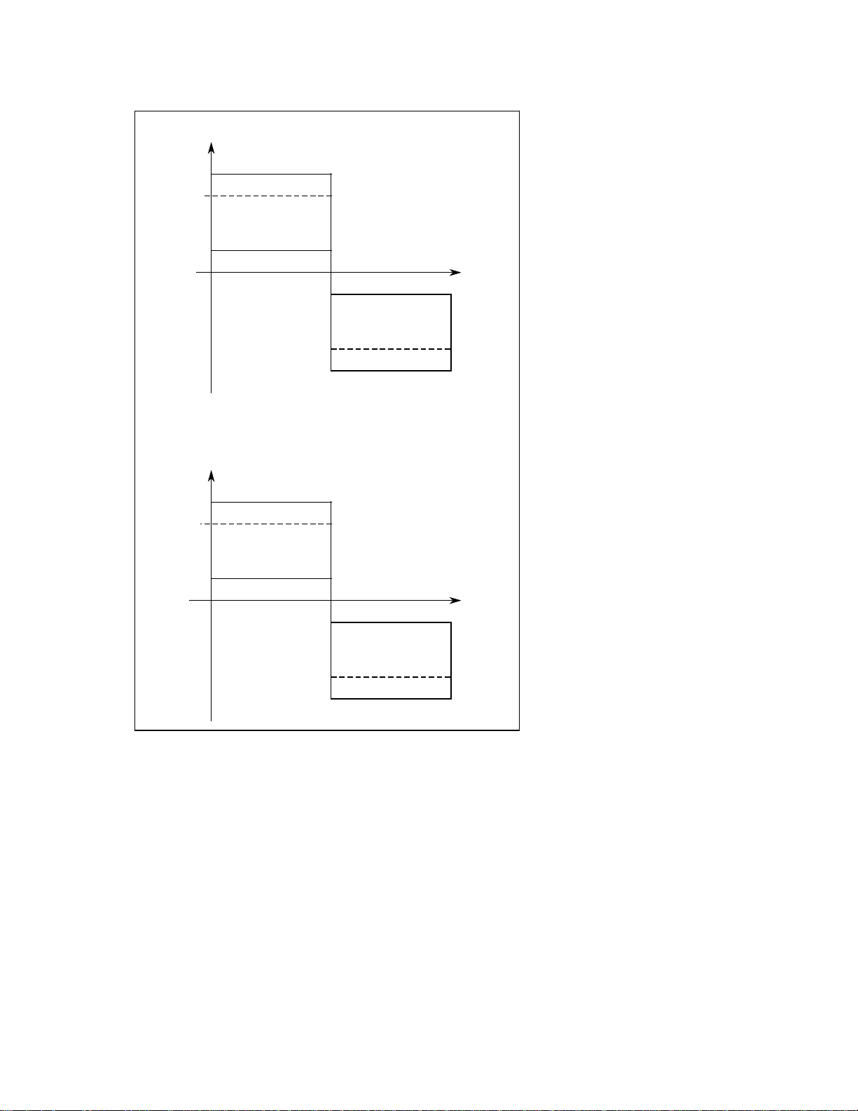
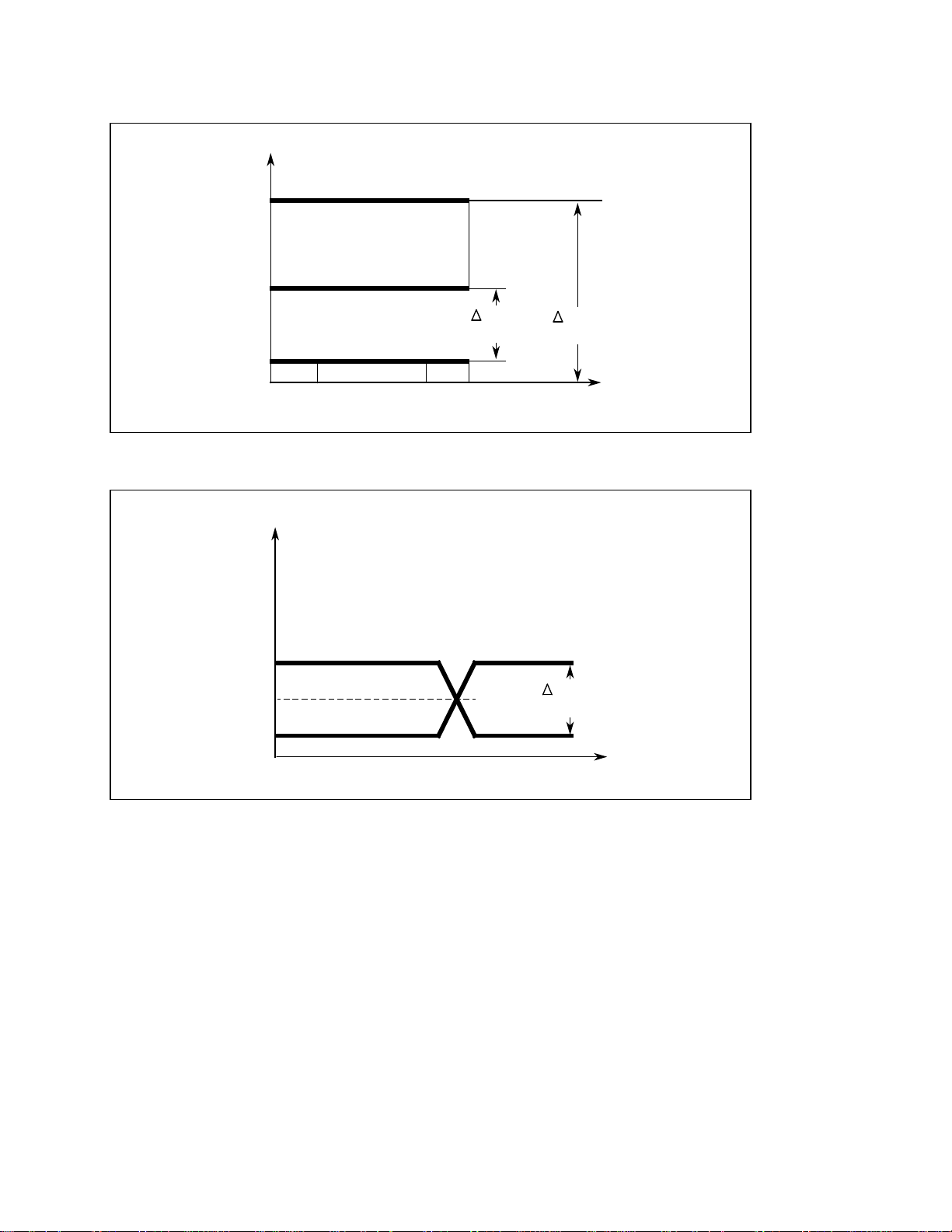
1.3 Polarity and voltage level assignment of V.24 interface signals
1.3 Polarity and voltage level assignment of V.24 interface signals
Data linesV
+15 V
+12 V
Logical ''L''
+3 V
0 V
–3 V
Logical ''H''
–12 V
–15 V
t
Control linesV
+15 V
+12 V
''On'' state
+3 V
0 V
–3 V
t
''Off'' state
–12 V
–15 V
Signal level of SINUMERIK interfaces: ±12 V
All signal levels refer to the signal ground E2 (102).
Within the transition range (+3 to –3 V) the signal state is undefined.
(Hysteresis range of the receiver circuits 75189 A)
© Siemens AG 1990 All Rights Reserved 6ZB5 410-0AQ02 1-3
SINUMERIK System 800, (PJ)
Page 12
1 V.24 (RS232C) Interface 10.88
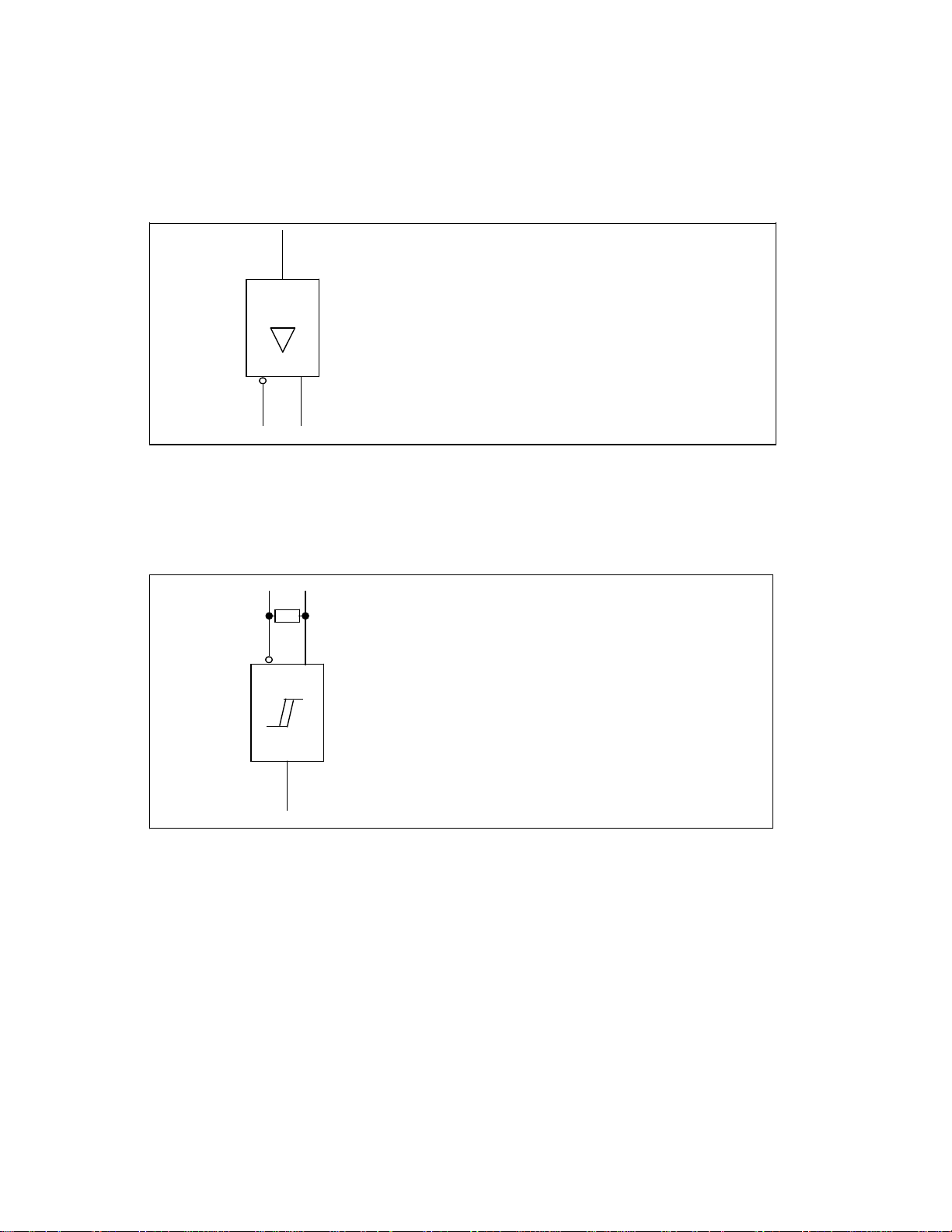
1.4 V.24 drivers and receivers
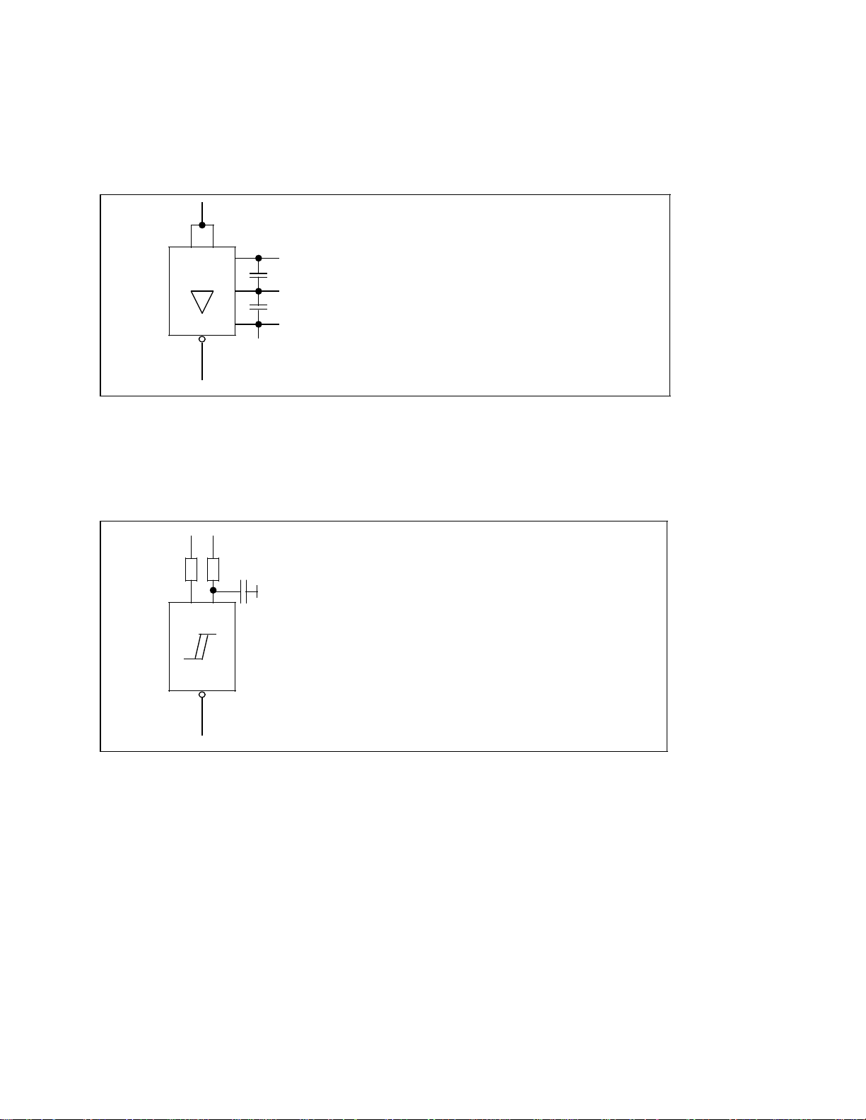
1.4 V.24 drivers and receivers
1.4.1 V.24 drivers
The V.24 output signals *TxD, RTS and DTR are generated in the V.24 driver block 75188
from the TTL signals of the USART 8251A.
75 188
TTL level
+12 V
&
0 V
–12 V
V.24 level
Data of circuit 75188
Max. supply voltage V
Max. output current
(current limited) I
Operating voltage
and V.24 level V
± 15 V
cc
10 mA
o
± 12 V
cc
1.4.2 V.24 receivers
The V.24 input signals * RxD, CTS and DSR are put onto the receiver circuits 75189 after
passing through an RC low-pass filter.
V
c
V.24 level
3904.7 k
Data of circuit 75189A
Max. input voltage V
cc
Input resistance 390
± 30 V
75 189 A
TTL level
1-4 © Siemens AG 1990 All Rights Reserved 6ZB5 410-0AQ02
SINUMERIK System 800, (PJ)
Page 13
07.90 1 V.24 (RS232C) Interface
1.5 Interface link to I/O device for V.24
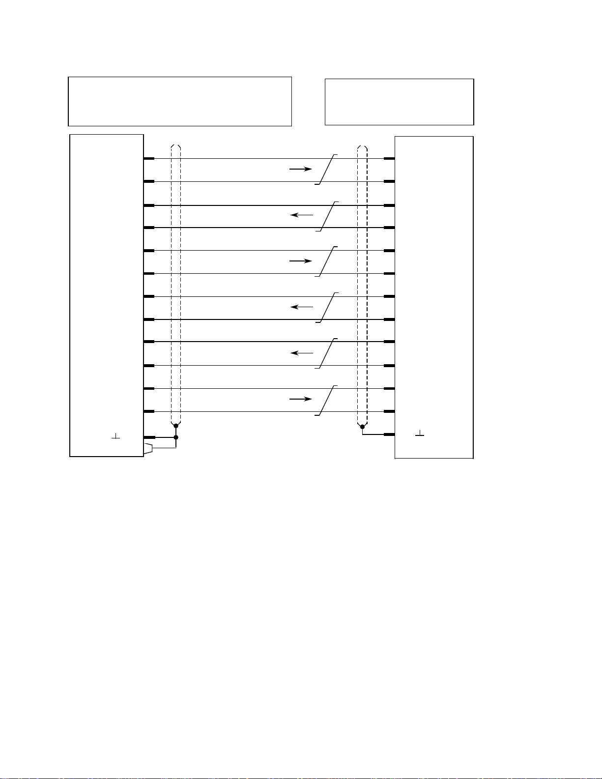
1.5 Interface link to I/O device for V.24
SINUMERIK
DTE DCE
* T x D
* R x D
RTS
CTS
DSR
2
O
3
O
4
O
5
O
6
O
Transmitted data
D1 (103)
Received data
D2 (104)
Request to send
S2 (105)
Clear to send
M2 (106)
Data set ready
M1 (107)
20
No device
DTE
3
O
* R x D
2
5
4
O
O
O
O
* T x D
CTS
RTS
DTR
DTR
MEXT
O
O
O
20
7
1
Data terminal ready
S1.2(108.2)
Signal ground
E2 (102)
Protective ground
E1 (101)
6
7
DSR
O
G
O
1
O
In all signal names and directions, the SINUMERIK is taken to be a DTE.
Which of the available control and message lines are used will depend on the I/O device. In
the simplest case, lines E2 and D1 suffice for a receiving device (printer, punch) or E2 and D2
for a sending device (reader). The specification of an I/O device determines how it is
connected.
In the interface link diagram, a device is assumed to comply with the RS232C standard. The
interfaces conform to VDI guideline 2880 with SINUMERIK as a DTE. If it is linked to an I/O
device which is also wired as a DTE, the appropriate lines must be crossed in the cable
(sender with receiver).
© Siemens AG 1990 All Rights Reserved 6ZB5 410-0AQ02 1-5
SINUMERIK System 800, (PJ)
Page 14

1 V.24 (RS232C) Interface 10.88
1.5 Interface link to I/O device for V.24
Some of the interfaces contain both the V.24 signals and the signals for 20 mA current loop
operation. A V.24 sender and a 20 mA sender may not be connected to a SINUMERIK interface at the same time.
As pins 10, 12, 13, 14, 16, 19, 21 and 24 are permanently reserved for
the 20 mA interface at the SINUMERIK end, it is important to make sure
that they are not connected to the I/O device in V.24 mode.
The interface is not set to V.24 or 20 mA operation by jumpers but by the pin assignments in
the cable plug.
1.6 Length of the transmission line
The maximum cable length for V.24 transmission is 30 m.
END OF SECTION
1-6
© Siemens AG 1990 All Rights Reserved 6ZB5 410-0AQ02
SINUMERIK System 800, (PJ)
Page 15

10.88 2 20 mA Current Loop Interface
2.1 General notes
2 20 mA Current Loop Interface
2.1 General notes
The 20 mA interface is configured to VDI guideline 2880 as a duplex interface with two pairs of
lines. At the SINUMERIK end it can be operated as an active or passive interface with the
available sources of current by changing the pin assignments in the cable connector. This
interface is also often referred to as a TTY interface.
The following is equivalent in V.24 and 20 mA interfaces (except the signal level):
20 mA
Signal V.24
+ –
Transmitted data
Received data
In the signal designations, the SINUMERIK is taken to be a DTE.
D1
D2
TTY2
TTY4
TTY1
TTY3
2.2 20 mA signal level
In the 20 mA interface, unlike the V.24 interface, information is not transmitted by the voltage
level but by impressed current.
Logical ”L”: I=0
Logical ”H”: I=20 mA
Level 1 Signal 20 mA±30 %
(max. open-circuit voltage
30 V)
0 signal 0 mA to 2 mA
Voltage for current loop source at
SINUMERIK =12 V
I=20 mA
I
Logical ”H”
( 0 V )
Logical ”L”
I= 0
(12 V)
© Siemens AG 1990 All Rights Reserved 6ZB5 410-0AQ02 2-1
SINUMERIK System 800, (PJ)
t
Page 16

2 20 mA Current Loop Interface 10.88
2.3 Interface link to I/O device for 20 mA
2.3 Interface link to I/O device for 20 mA
20 mA interfaces are duplex interfaces with two pairs of lines. They can be operated as active
or passive interfaces at the SINUMERIK end.
• Active interface:
SINUMERIK supplies the 20 mA line current.
• Passive interface:
The peripheral unit supplies the 20 mA line current.
The interface is set to ''active'' or ''passive'' at the SINUMERIK end by the wiring in the cable
connector not by jumper setting on the module.
The line current should always be checked when the loop is closed (approx. 20 mA).
Refer also to Section 1.5.
2-2
© Siemens AG 1990 All Rights Reserved 6ZB5 410-0AQ02
SINUMERIK System 800, (PJ)
Page 17

07.90 2 20 mA Current Loop Interface
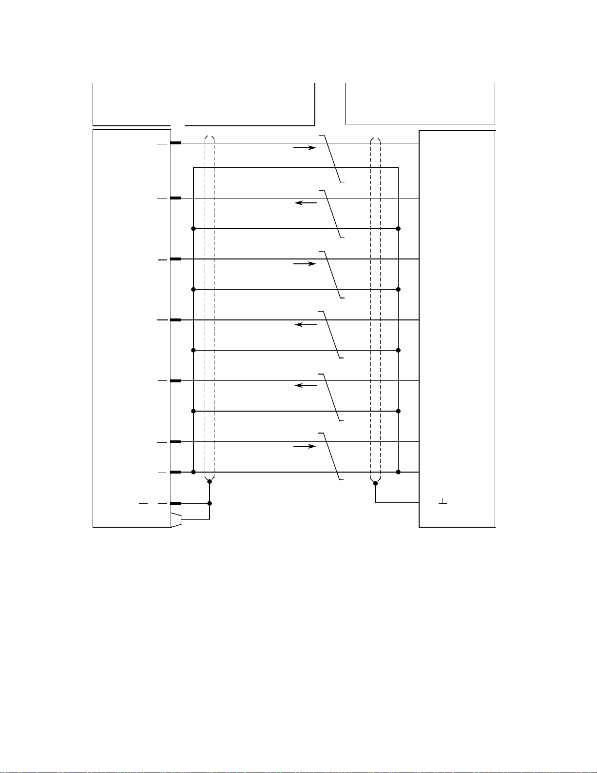
2.3.1 Duplex interface
2.3.1 Duplex interface Active at SINUMERIK end
SINUMERIK
DTE DCE
0 V (R)
TTY 3
–
+
TTY 4
R 20 mA
0 V (T)
TTY 1
–
O
O
O
O
O
O
24
14
13
16
21
19
Received data –
Received data +
19
10
I/O device
DTE
O
O
+
TTY 2
T 20 mA
O
O
O
10
12
1
Transmitted data –
Transmitted data +
14
13
O
O
1
O
© Siemens AG 1990 All Rights Reserved 6ZB5 410-0AQ02 2-3
SINUMERIK System 800, (PJ)
Page 18
2 20 mA Current Loop Interface 10.88
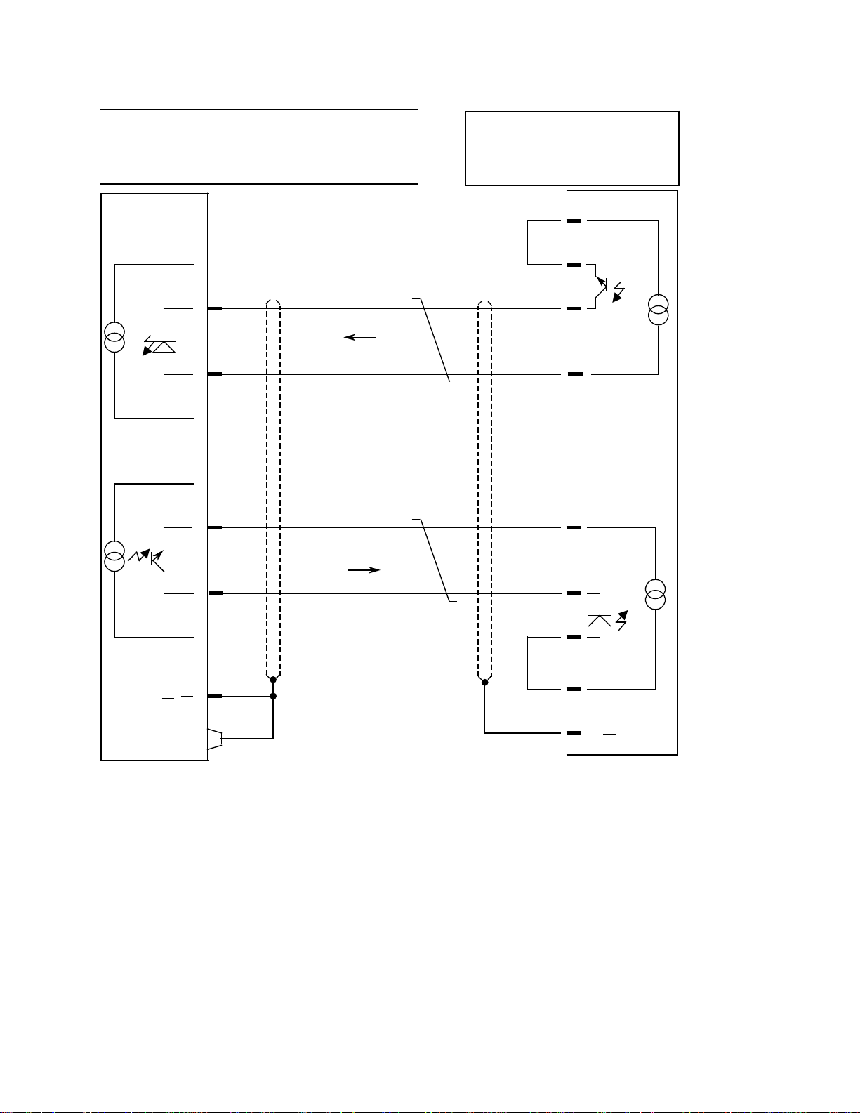
2.3.2 Duplex interface
2.3.2 Duplex interface Passive at the SINUMERIK end
SINUMERIK
DTE DCE
24
O
–
+
TTY 3
TTY 4
O
O
O
14
13
16
21
Received data –
Received data +
O
Transmitted data +
–
TTY 1
O
19
19
12
10
24
21
I/O device
DTE
O
O
–
O
+
O
O
+
TTY 2
O
O
O
10
12
1
Transmitted data –
16
14
13
O
O
O
1
O
In all signal names and directions, the SINUMERIK is taken to be a DTE.
The specification of the I/O device determines how it is connected.
In the interface link diagram, the I/O device is assumed to comply with the VDI 2880
specification.
2.4 Length of the transmission line
The maximum cable length for the 20 mA current loop interface is 1 km.
–
+
2-4
END OF SECTION
© Siemens AG 1990 All Rights Reserved 6ZB5 410-0AQ02
SINUMERIK System 800, (PJ)
Page 19

10.88 3 RS 422 Interface
3.1 General notes
3 RS 422 Interface
3.1 General notes
The function of the signals in the RS 422 interface is identical to those of the V.24 interface.
However, instead of the V.24 signal level, transmission is via two-wire cables using differential
drivers and receivers.
The RS 422 interface combines the advantages of the V.24 interface (modem capability by
control signals) with those of the 20 mA interface (large transmission distances).
The following signals are the same for the V.24 interface and the RS 422 interface (except
signal level):
Data signals
Signal V.24 RS 422
Transmitted data
Receive data
Control signals
Signal V.24 RS 422
Data terminal ready
Request to send
Data set ready
Clear to send
D1
D2
S1.2
S2
M1
M2
TxD
RxD
DTR
RTS
DSR
CTS
© Siemens AG 1990 All Rights Reserved 6ZB5 410-0AQ02 3-1
SINUMERIK System 800, (PJ)
Page 20
3 RS 422 Interface 10.88
3.2 Polarity and voltage level assignment of the RS 422 interface
3.2 Polarity and voltage level assignment of the RS 422 interface
V
5 V
Logical ”H”
2.5 V
0.5 V
0 V
VOH 2.5 V
1.5 V
VOL 0.5 V
Logical ”L”
V
min.
=2V
V
max.
=5V
t
V
Output Y
V
min.
=2V
Output Z
t
The voltage levels refer to the reference voltage of the driver circuit AM 26 LS 31.
The voltage between the differential lines is
min
max
= 2 V
= 5 V
© Siemens AG 1990 All Rights Reserved 6ZB5 410-0AQ02
SINUMERIK System 800, (PJ)
V
V
3-2
Page 21
10.88 3 RS 422 Interface
3.3.1 RS 422 drivers
3.3 RS 422 drivers and receivers
3.3.1 RS 422 drivers
The RS 422 output signals are generated from the TTL signals of the USART 8251 via the AM
26 LS 31 line drivers.
TTL level
Data of the AM 26 LS 31 circuit
cc
oL
oH
= 5 V
= 0.5 V
= 2.5 V
AM 26 LS 31
Supply voltage V
Max. output voltage V
Min. output voltage V
Differential voltage 2 ... 5 V
RS 422 level
Z Y
3.3.2 RS 422 receivers
The RS 422 input signals are converted to TTL signals via the AM 26 LS 33 line receivers.
150
RS 422 level
AM 26 LS 33
Data of the AM 26 LS 33 circuit
Supply voltage V
= 5 V
cc
Input parallel
resistance 150 Ohm
Differential operation
voltage 2 ... 5 V
TTL level
© Siemens AG 1990 All Rights Reserved 6ZB5 410-0AQ02 3-3
SINUMERIK System 800, (PJ)
Page 22
3 RS 422 Interface 07.90
3.4 Interface link to I/O device for RS 422
3.4 Interface link to I/O device for RS 422
SINUMERIK
DTE DCE
2
* T x D
T x D
* R x D
R x D
R
S
4
2
* RTS
2
s
i
g
n
* CTS
a
l
s
* DSR
* DTR
RTS
CTS
DSR
DTR
O
15
O
3
O
16
O
4
O
17
O
5
O
18
O
6
O
19
O
20
O
8
O
1
O
Transmitted data
D1 (103)
Received data
D2 (104)
Request to send
S2 (105)
Clear to send
M2 (106)
Data set ready
M1 (107)
Data terminal ready
S1.2 (108.2)
Protective ground
E1 (101)
I/O device
DTE
3
O
16
O
2
O
15
O
5
O
18
O
4
O
17
O
20
O
8
O
6
O
19
O
1
* R x D
R x D
* T x D
T x D
CTS
* CTS
RTS
* RTS
DTS
* DTR
DSR
* DSR
O
In all signal names and directions, the SINUMERIK is taken to be a DTE.
Which of the control and message lines are used will depend on the I/O device. The speci-
fication I/O device peripheral unit determines how it is connected.
In the interface link diagram, a device is assumed to comply with the SINUMERIK specifica-
tion. The RS 422 interface is on a special connector.
3.5 Length of the transmission line
The maximum cable length for RS 422 transmission is 1 km.
3.6 Level conversion from V.24 to RS 422
With the SINUMERIK System 800 the V.24 level of the V.24 interfaces can be converted into a
RS 422 level with a special cable. The converter electronics are integrated into the specific
SINUMERIK cable connector (housing of fibre glass conductor).
The adjustable interfaces are listed in Section 7.1 corresponding to the controls.
END OF SECTION
3-4
© Siemens AG 1990 All Rights Reserved 6ZB5 410-0AQ02
SINUMERIK System 800, (PJ)
Page 23
10.88 4 Interface Overview
4.1 Pin assignments of the data interfaces
4 Interface Overview
4.1 Pin assignments of the data interfaces
4.1.1 Pin assignments on the V.24/20 mA universal interface
D-Sub, 25-pin, socket on SINUMERIK.
Pin Signal name Interface Signal name to DIN 66020
SINUMERIK assignment VDI 2880
(English from CCITT recommendation)
(referring to SINUMERIK as a DTE)
1 Protective ground E1 (101)
2 *TxD V.24 Transmitted data D1 (103)
3 *RxD V.24 Received data D2 (104)
4 RTS V.24 Request to send S2 (105)
5 CTS V.24 Clear to send M2 (106)
6 DSR V.24 Data set ready M1 (107)
7 MEXT V.24 Signal ground E2 (102)
8
9
10 TTY2 20 mA Transmitted data+
11
12 T 20 mA 20 mA Transmit source
13 TTY4 20 mA Received data +
14 TTY3 20 mA Received data –
15
16 R 20 mA 20 mA Receive source
17
18
19 TTY1 20 mA Transmitted data –
20 DTR V.24 Data terminal ready S1.2 (108.2)
21 0V (T) 20 mA Current return
22
23
24 0V (R) 20 mA Current return
25
© Siemens AG 1990 All Rights Reserved 6ZB5 410-0AQ02 4-1
SINUMERIK System 800, (PJ)
Page 24

4 Interface Overview 10.88
4.1.2 Pin assignments of the RS 422 interface
4.1.2 Pin assignments of the RS 422 interface
D-Sub, 25-pin, socket on SINUMERIK
Pin Signal name Interface Signal name to DIN 66020
SINUMERIK assignment (English from CCITT recommendation)
(referring to SINUMERIK as a DTE)
1 Protective ground E1 (101)
2 *TxD RS 422 Transmitted data D1 (103)
3 *RxD RS 422 Received data D2 (104)
4 RTS RS 422 Request to send S2 (105)
5 CTS RS 422 Clear to send M2 (106)
6 DSR RS 422 Data set ready M1 (107)
7
8 *DTR RS 422 Data terminal ready S1.2 (108.2)
9
10
11
12
13
14
15 TxD RS 422 Transmitted data D1 (103)
16 RxD RS 422 Received data D2 (104)
17 *RTS RS 422 Request to send S2 (105)
18 *CTS RS 422 Clear to send M2 (106)
19 *DSR RS 422 Data set ready M1 (107)
20 DTR RS 422 Data terminal ready S1.2 (108.2)
21
22
23
24
25
4-2 © Siemens AG 1990 All Rights Reserved 6ZB5 410-0AQ02
SINUMERIK System 800, (PJ)
Page 25

07.90 4 Interface Overview
4.2 Explanation of signal names
4.2 Explanation of signal names
CTS Clear to Send
DSR Data Set Ready
DTR Data Terminal Ready
MEXT External Ground
RTS Request to Send
RxD Receive Data V.24
R20mA Receive Source 20 mA
TxD Transmit Data V.24
TTY1 Teletype (– 20 mA) Transmit Data
TTY2 Teletype (+20 mA) Transmit Data
TTY3 Teletype (– 20 mA) Receive Data
TTY4 Teletype (+20 mA) Receive Data
T20mA Transmit Source 20 mA
0V(R) 0V – Receive 20 mA
0V(T) 0V – Transmit 20 mA
4.3 Format of a serially transmitted character
T x D
R x D
Quiescent
state
Start
element
21
Data bits
6 87543
Stop
elements
Parity
bit (optional)
In the SINUMERIK universal interface the 8th bit of a character, which is normally the parity
bit, is designated as 8th data bit.
The parity bit is an optional 9th bit added to an ASCII character on even, and to an EIA
character on odd bit combinations. The 8th bit is always part of the data.
An additional parity bit (9th. bit) may be generated via setting data if desired for adaptation to
certain I/O devices.
© Siemens AG 1990 All Rights Reserved 6ZB5 410-0AQ02 4-3
SINUMERIK System 800, (PJ)
Page 26
4 Interface Overview 10.88
4.4 Block diagrams of the data interfaces
4.4 Block diagrams of the data interfaces
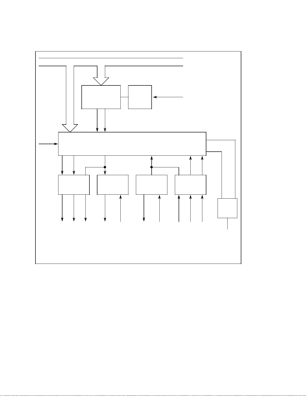
4.4.1 Block diagram of V.24/20 mA universal interface
Data bus DB
Select (1)
Baud rate
generator
DTRRTS
V.24
driver
RTS DTR * T x D
V.24
Output
Scaler
T x C
R x C
U SART
20 mA
driver
TTY 2 TTY 1 TTY 4 TTY 3 CTS DSR
20 mA
Transmit
1)
20 mA
receiver
Duplex
Receive
CPU frequency
R x DT x D
* R x D
V.24
receiver
V.24
Input
DSRCTS
R x RDYT x RDY
1
IR
Interrupt
1)
USART = Universal Synchronous Asynchronous Receiver Transmitter
Its tasks are:
• Conversion of 8 bits parallel to 8 bits serial
• Transmitting and receiving at different baud rates (possibly simultaneously)
• Error detection
• Define and check parity
4-4
© Siemens AG 1990 All Rights Reserved 6ZB5 410-0AQ02
SINUMERIK System 800, (PJ)
Page 27
07.90 4 Interface Overview
4.4.2 Block diagram of an RS 422 interface
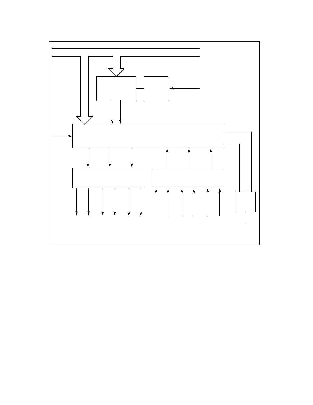
4.4.2 Block diagram of an RS 422 interface
Data bus DB
Select (1)
Baud rate
generator
T x C
R x C
U SART
RTS DTR T x D DSRCTSR x D
RS 422
driver
RTS * RTS DTR
* DTR
* Tx D
Tx D
RS 422 Output RS 422 Input
Scaler
* R x D
CPU frequency
RS 422
receiver
R x D CTS
1
* CTS DSR *DSR
IR
Interrupt
END OF SECTION
© Siemens AG 1990 All Rights Reserved 6ZB5 410-0AQ02 4-5
SINUMERIK System 800, (PJ)
Page 28

10.88 5 Adapting the Interfaces to I/O Devices
5.1 General notes
5 Adapting the Interfaces to I/O Devices
5.1 General notes
Peripheral devices are subdivided according to the type of data transmission:
• Line-controlled devices:
– Control via the control lines DSR, DTR, CTS, RTS
• Uncontrolled devices:
– Asynchronous transmission without control
• Character-controlled devices:
– Control using control characters on the data lines
Each interface and data direction is defined at the SINUMERIK end for the I/O device using
setting data (see selection tables). The control lines are activated by connecting them.
On startup the default values of the machine data and setting data adapt the interface to the
Siemens PT 80 page printer (universal device).
© Siemens AG 1990 All Rights Reserved 6ZB5 410-0AQ02 5-1
SINUMERIK System 800, (PJ)
Page 29
5 Adapting the Interfaces to I/O Devices 03.91
5.2 Setting data
5.2 Setting data
SINUMERIK System 800 has one set of 8 bytes per interface for adapting the I/O devices. The
input and output directions are set separately.
The setting of the EIA code for special characters ”@”, ”:”, ”=”, ”[”, ”]” and ”,” and the
definition for the character ”End of transmission” is entered in 7 additional bytes for two
interfaces.
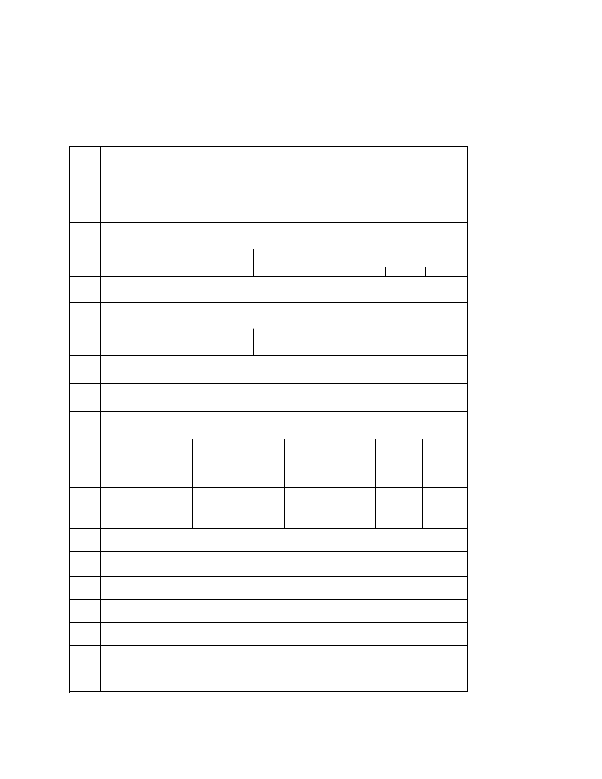
Byte
No.
1
2
3
4
5
6
7
8
Function
Bit
7 6 5 4 3 2 1 0
Device coding - input-
Transmission format - input -
Type of
parity
Parity
bit
Baud rateStop elements
Device coding - output -
Transmission format - output -
Stop elements
Type of
parity
Xon character (e.g. DC1 = 11
Xoff character (e.g. DC3 = 93
Parity
bit
hex
hex
Baud rate
)
)
Special bits
Output
without
1st Xon
character
Program
start
with LF
End of
block
CR LF
Output in
EIA
code
Stop at
character
end of
trans-
mission
Evaluate
data set
ready
DSR
Output
without
leader
and
trailer
Delete
program
without
reorgan.
Read-in
progr. of
systems
3, 8
Switch off
time
watchdog
9
10
11
12
13
14
15
EIA code for ”@” (e.g. 6D
EIA code for ”:” (e.g. 46
Code for ”End of transmission” (e.g. ETX=03
EIA Code for ”=” (e.g. 1C
EIA code for ”[”
EIA code for ”]”
EIA code for ”,”
hex
hex
Hex
)
)
in ISO)
hex
)
5-2 © Siemens AG 1990 All Rights Reserved 6ZB5 410-0AQ02
SINUMERIK System 800, (PJ)
Page 30

07.90 5 Adapting the Interfaces to I/O Devices
5.2.1 Explanation of the setting data
5.2.1 Explanation of the setting data
Specific data per interface
Byte 1, 3: Device code
00
= Line controlled devices
Hex
(data traffic according to standard)
= Xon/Xoff character-controlled devices
01
Hex
= SINUMERIK reader T10 and T20
02
Hex
= Siemens PLC programmer
04
Hex
PG 670/675/685/635/750/615
Device setting data are listed in the selection table in Section 8.1.
Byte 2, 4: Transmission format
– Bit 3 ... 0: Baud rate
0000 = 110 baud
0001 = 150 baud
0010 = 300 baud
0011 = 600 baud
0100 = 1200 baud
0101 = 2400 baud
0110 = 4800 baud
0111 = 9600 baud
– Bit 4: Parity bit
0 = without parity
1 = with parity
Determines whether after the 8th data bit a 9th bit should be generated and transmitted as a
parity bit.
– Bit 5: Type of parity
0= even
1= odd
Determines whether the additionally generated parity bit should complement the 8-bit data
on even or odd bit combinations.
If bit 4 is 0, bit 5 has no meaning.
– Bit 7 and 6: Number of stop elements
00=1 stop element
01=1 stop element
10=1 1/2 stop elements
11=2 stop elements
© Siemens AG 1990 All Rights Reserved 6ZB5 410-0AQ02 5-3
SINUMERIK System 800, (PJ)
Page 31

5 Adapting the Interfaces to I/O Devices 10.88
5.2.1 Explanation of the setting data
Byte 5: Xon character
Sets the Xon character for character-controlled transmission.
Byte 6: Xoff character
Sets the Xoff character for character-controlled transmission.
Byte 7: Special bits
– Bit 0 Read in subroutines of Systems 3 and 8
0 = Read in main programs and subroutines to System 800 format
1 = Read in main programs and subroutines to System 3, 8 format
When subroutines are read in to System 3, 8 format the identifier 00 of the subroutine no. is
eliminated.
– Bit 1 Output without leader and trailer
0 = Data output with leader and trailer (as punched tape)
1 = Data output without leader and trailer (in memory)
– Bit 2 Evaluate data set ready DSR
0 = Line ”DSR” (pin 6) is not evaluated
1 = Line ”DSR” (pin 6) is evaluated
– Bit 3 Stop at ”End of transmission” character
0=Read-in stop at M02/M30
1=Read-in stop at end of transmission character
Allows several programs to be read in en bloc (e.g. the main programs, subroutines, tool
data and blocks belonging to a workpiece)
– Bit 4 Output in the EIA code
0 = Output in ISO code
1 = Output in EIA code
– Bit 5 End of block CR LF
0 = End of block when output with LF CR CR
1 = End of block when output with CR LF
– Bit 6 Program start with LF
0 = Read-in begin with %
1 = Read-in begin with LF
Allows part program to be read in. The next LF read is interpreted as the beginning of a
program and this program is stored in the part program memory as %0.
– Bit 7 Output without 1st Xon character
0 = Output begin after request via Xon character
1 = Output begin without request
When character control devices are connected, data output is initiated with data start
without waiting for the Xon character from the external unit. Further starts and stops use
the Xon, Xoff characters.
5-4
© Siemens AG 1990 All Rights Reserved 6ZB5 410-0AQ02
SINUMERIK System 800, (PJ)
Page 32

07.90 5 Adapting the Interfaces to I/O Devices
5.2.1 Explanation of the setting data
Byte 8: Special bits
– Bit 0 Time watchdog switched off
0 = Time watchdog active
If on transmission no character is sent for 60 s, the NC interrupts the transmission line
and sets interrupt 22.
1 = Time watchdog switched off
– Bit 1 Delete program without reorganizing
0 = Reorganize
After a program has been deleted via V.24, automatic reorganization is activated.
1 = No reorganizing
After a program has been deleted via V.24, automatic reorganization is suppressed.
Data common to both interfaces
Byte 9
EIA code for ”@”
Byte 10 EIA code for ”:”
Definition of substitute characters for the”@” and ”:” characters missing in the EIA code.
Byte 11 Code for
Definition of character for end of transmission in ISO code (e.g. ETX = 03
Byte 12 EIA code for
”End of transmission”
”=”
) or in EIA code.
Hex
Definition of substitute character for the ”=” character missing in the EIA code.
Byte 13
EIA code for ” [ ”
Definition of substitute character for the ” [ ” character missing in the EIA code.
Byte 14 Code for
” ] ”
Definition of substitute character for the ” ] ” character missing in the EIA code.
Byte 15 EIA code for
”,”
Definition of substitute character for the ”,” character missing in the EIA code.
© Siemens AG 1990 All Rights Reserved 6ZB5 410-0AQ02 5-5
SINUMERIK System 800, (PJ)
Page 33

5 Adapting the Interfaces to I/O Devices 10.88
5.3 Notes on the format of special characters
5.3 Notes on the format of special characters
Special characters and substitute characters must always be entered in the setting data
including the paraity bit (8th data bit).
It is important to note that the bit combination is even when using the ISO code and odd when
using the EIA code.
Example:
The Xoff character DC 3 with ASCII code 13
item of setting data in ISO code as 93
HEX
.
is odd and must therefore be entered as an
HEX
5.4 Notes on using the EIA code
Not all ISO characters can be represented in the EIA code. For this reason, interrupt 33
(program read in program stored) can occur when a program written in ISO code and
stored in the NC is compared with its equivalent converted into EIA code.
Example:
Block in NC memory
N 10 ... (... =
....)*
Block output in EIA code
N 10 ... (...
....)*
END OF SECTION
5-6
© Siemens AG 1990 All Rights Reserved 6ZB5 410-0AQ02
SINUMERIK System 800, (PJ)
Page 34

10.88 6 Signal Timing for Data Transmission
6.1 Signal timing with line-controlled devices
6 Signal Timing for Data Transmission
6.1 Signal timing with line-controlled devices
6.1.1 Data input (I/O device to NC)
Switch off NC
End of reading
in
ETX
Data
DTR
DSR
CTS
RTS
RxD
TxD
Switch on NC
I/O device ready No longer ready
NC buffer free
Data
Data Start
NC buffer full
When the NC is switched on, DTR of all interfaces goes to High = ”1”. If the readiness of the
device is to be evaluated, the DSR line must be connected.
Reading in the data is started with ”Data Start” and controlled with ”RTS”. With data start,
RTS goes to ”1” and the I/O device can send data.
If the NC cannot keep up with data input, transmission is stopped by cancelling RTS. When
the NC buffer becomes free again RTS is reset to ”1” and transmission is again enabled.
If the NC reads the ”End of Transmission” character (M02 or M30 or ETX), transmission is
stopped by cancelling of RTS.
© Siemens AG 1990 All Rights Reserved 6ZB5 410-0AQ02 6-1
SINUMERIK System 800, (PJ)
Page 35

6 Signal Timing for Data Transmission 12.95
6.1.2 Data output (NC to I/O device)
6.1.2 Data output (NC to I/O device)
DTR
DSR
CTS
RTS
RxD
TxD
Data
Data Start
Data
Data End
When the NC is switched on, DTR of all interfaces goes to ”1”. If the readiness of the I/O
device is to be evaluated the DSR line must be connected.
If the external device is to control data transmission, the CTS line must be connected.
Data read-out is started with Data Start, when CTS is ”1” (if connected). If the device cannot
keep up with data input it stops transmission by cancelling CTS. If its buffer is free again, CTS
is reset to ”1” and transmission restarted. The NC terminates data transmission when the
end of program has been output or ETX and a trailer.
In the SINUMERIK 805/810/820/840/850/880, the RTS signal stays at ”0” during data output.
6-2
© Siemens AG 1990 All Rights Reserved 6ZB5 410-0AQ02
SINUMERIK System 800, (PJ)
Page 36

12.95 6 Signal Timing for Data Transmission
6.1.2 Data output (NC to I/O device)
DTR
DSR
CTS
RTS
RxD
TxD
Data
Data Start
Data
Data End
In the SINUMERIK 840C Basic Version and SINUMERIK 840C OEM Version for Windows, the
signal chart is slightly different from that above.
The RTS signal is reset to ”0” on activating the interface for data output, i.e. with Data Start
on ”1” and at the end of data transfer.
© Siemens AG 1990 All Rights Reserved 6ZB5 410-0AQ02 6-3
SINUMERIK System 800, (PJ)
Page 37

6 Signal Timing for Data Transmission 10.88
6.2.1 Data input (I/O device to NC)
6.2 Signal timing with character-controlled devices
6.2.1 Data input (I/O device to NC)
Switch on NC
Switch off NC
DTR
I/O device ready No longer ready
DSR
(CTS)
(RTS)
RxD
TxD
DC Start
Data Start
Data Stop
DataData
Data Start
ETX
When the NC is switched on, the DTR of all signals goes to ”1”. If the readiness of the I/O
device is to be evaluated the DSR line must be connected.
With ”Data Start” the NC sets the RTS signal to ”1”. RTS is only cancelled at the end of
transmission or if an error occurs.
The NC enables reading in data by transmitting the character ”Xon” (setting byte no. 5). The
I/O device then transmits data to the NC. If the NC cannot keep up with data input it stops
transmission by transmitting the character ”Xoff” (setting byte no. 6).
As the I/O device generally cannot stop at a precise character the NC is able to read a few
more characters. If the NC is ready to receive again, transmission is again enabled by ”Xon”.
If the NC reads the ”End of Transmission” character (M02 or M30 or ETX), it transmits the
character ”Xoff” and sets RTS to ”0”.
If the CTS line is connected it must already be ”1” at Data Start and may only be set to ”0”
after the end of transmission.
In character-controlled transmission, the RTS and CTS lines do not normally have to be
connected to the external device.
6-4
© Siemens AG 1990 All Rights Reserved 6ZB5 410-0AQ02
SINUMERIK System 800, (PJ)
Page 38

10.88 6 Signal Timing for Data Tranmission
6.2.2 Data output (NC to I/O device)
6.2.2 Data output (NC to I/O device)
DTR
DSR
(CTS)
(RTS)
RxD
TxD
Switch on NC
I/O device ready No longer ready
)(
Data
Data Start
Switch off NC
Data
Daten End
When the NC is switched on, the DTR of all interfaces goes to ”1”. If the readiness of the I/O
device is to be evaluated the DSR line must be connected.
With ”Data Start” the NC sets the RTS signal to ”1”. RTS is only withdrawn at the end of
transmission or if an error occurs.
The NC starts reading out data after it has received the ”Xon” character. If bit 7 of setting
data 7 (output without 1st Xon character) is set, the NC starts reading out data with Data Start.
If the I/O device cannot keep up data input, it stops transmission by sending the control
character ”Xoff”. The NC can then send two more characters before transmission is
terminated. If the I/O device is ready again it restarts transmission by sending the control
character Xon.
The NC terminates transmission after output of end of program or ETX (and a trailer) by
cancelling RTS.
If the CTS line is connected this must already be ”1” at Data Start and may only be set to
”0” after end of transmission.
For character-controlled transmission, RTS and CTS do not normally need to be connected to
the external device.
END OF SECTION
© Siemens AG 1990 All Rights Reserved 6ZB5 410-0AQ02 6-5
SINUMERIK System 800, (PJ)
Page 39

07.90 7 Serial interfaces on the SINUMERIK System 800
7.1.1 SINUMERIK 805
7 Serial Interfaces on the SINUMERIK
System 800
7.1 Interfaces on the various controls
7.1.1 SINUMERIK 805
1st interface: PCB 6FX1144-4BA, connector X122 central controller
V.24 and 20 mA interface
25-way connector, D-subminiature, socket
Housing of the cable connector
SINUMERIK type, position 1 below
optional: slide latch type
2nd interface (option): PCB 6FX1144
V.24 interface
can be used for adaptation of RS 422 special cable
25-way connector, D-subminiature, socket
Housing of the cable connector
SINUMERIK type, position 1 below
optional: slide latch type
-4BA, connector X132 central controller
7.1.2 SINUMERIK 810 GA1
1st interface: Operator panel front
V.24 and 20 mA interface
(Connected within the SINUMERIK by cable on PCB
6FX1125-8AB, connector X111
Slot A6, X111)
25-way connector, D-subminiature, socket
Housing of the cable connector:
slide latch type, position 1 below
2nd interface (option): PCB 6FX1125
Slot A6, X121
-8AB, connector X121 operator panel rear
V.24 interface
25-way connector , D-subminiature, socket
Housing of the cable connector:
SINUMERIK type, position 1 below
optional: slide latch type
© Siemens AG 1990 All Rights Reserved 6ZB5 410-0AQ02 7-1
SINUMERIK System 800, (PJ)
Page 40

7 Serial interfaces on the SINUMERIK System 800 07.90
7.1.3 SINUMERIK 810 GA2/820 GA2
7.1.3 SINUMERIK 810 GA2/820 GA2
1st interface: Operator panel front
V.24 and 20 mA interface
(Connected within the SINUMERIK by cable on PCB
6FX1132-8BB, connector X121
Slot A6, X121)
25-way connector, D-subminiature, socket
Housing of the cable connector:
slide latch type, position 1 below
2nd interface (option): PCB 6FX1132
-8BB, connector X131 operator panel rear
Slot A6, X131
V.24 interface
can be used for adaptation of RS 422 special cable
25-way connector, D-subminiature, socket
Housing of the cable connector:
SINUMERIK type, position 1 below
optional: slide latch type
7.1.4 SINUMERIK 810 GA3/820 GA3
1st interface: Operator panel, front
V.24 and 20 mA interface
(Connected within the SINUMERIK by cable on
PCB 6FX1138-5BA, connector X121
slot A6, X121)
25-way connector, D-subminiature, socket
Housing of the cable connector:
SINUMERIK type, position 1 below
2nd interface (option): PCB 6FX1138
slot A6, X131
V.24 interface
can be used for adaptation of RS 422 special cable
25-way connector, D-subminiature, socket
Housing of the cable connector:
SINUMERIK type, position 1 below
optional: slide latch type
7-2
-5BA, connector X131 operator panel, rear
© Siemens AG 1990 All Rights Reserved 6ZB5 410-0AQ02
SINUMERIK System 800, (PJ)
Page 41

07.90 7 Serial interfaces on the SINUMERIK System 800
7.1.5 SINUMERIK 840
7.1.5 SINUMERIK 840
1st interface: Maschine control panel front
V.24 and 20 mA interface
(Connected within the SINUMERIK by 6FC9344-1F cable on
PCB 6FC1123-3CA, connector X131 central controller
Slot B1, X131)
25-way connector , D-subminiature, socket
Housing of the cable connector:
slide latch type, position 1 below
2nd interface (option): PCB 6FX1120
Slot A4, X131
V.24 interface
can be used for adaptation of RS 422 special cable
25-way connector, D-subminiature, socket
Housing of the cable connector:
SINUMERIK type, position 1 below
optional: slide latch type
-4BA, connector X131operator panel rear
© Siemens AG 1990 All Rights Reserved 6ZB5 410-0AQ02 7-3
SINUMERIK System 800, (PJ)
Page 42

7 Serial interfaces on the SINUMERIK System 800 07.90
7.1.6 SINUMERIK 850
7.1.6 SINUMERIK 850
1st interface: Machine control panel front
V.24 and 20 mA interface
(Connected within the SINUMERIK by cable on PCB
6FX1120-4BA, connector X121
Slot A4, X121)
25-way connector , D-subminiature, socket
Housing of the cable connector:
slide latch type, position 1 below
2nd interface (option): PCB 6FX1120
Slot A4, X131
V.24 interface
can be used for adaptation of RS 422 special cable from
PCB 6FX1120-4BA02
25-way connector, D-subminiature, socket
Housing of the cable connector:
SINUMERIK type, position 1 below
optional: slide latch type
3rd interface: PCB 6FX1120
Slot B3, X121
V.24 und 20 mA interface
can be used for adaptation of RS 422 special cable from
PCB 6FX1120-4BA02
25-way connector, D-subminiature, socket
Housing of the cable connector:
SINUMERIK type, position 1 below
optional: slide latch type
4th interface (option): PCB 6FX1120
Slot B3, X131
-4BA, connector X131 operator panel rear
-4BA, connector X121 central controller
-4BA, connector X131 central controller
7-4
V.24 interface
can be used for adaptation of RS 422 special cable from
PCB 6FX1120-4BA02
25-way connector, D-subminiature, socket
Housing of the cable connector:
slide latch type, position 1 below
optional: slide latch type
© Siemens AG 1990 All Rights Reserved 6ZB5 410-0AQ02
SINUMERIK System 800, (PJ)
Page 43

07.90 7 Serial interfaces on the SINUMERIK System 800
7.1.7 SINUMERIK 880
7.1.7 SINUMERIK 880
1st interface: Operator panel front
V.24 and 20 mA interface
(Connected within the SINUMERIK by cable on
PCB 6FX1120-4BB, connector X121
Slot A4, X121)
25-way connector, D-subminiature, socket
Housing of the cable connector:
Slide latch type, position 1 below
2nd interface (option): PCB
6FX1120-4BB, connector X131 operator panel rear
Slot A4, X131
V.24 interface
can be used for adaptation of RS 422 special cable
25-way connector, D-subminiature, socket
Housing of the cable connector:
SINUMERIK type, position 1 below
optional: slide latch type
3rd interface: PCB 6FX1120
Slot B2, X121 (types 1, 2, 3, 7)
Slot B3, X121 (types 4, 5, 6)
V.24 and 20 mA interface
can be used for adaptation of RS 422 special cable
25-way connector, D-subminiature, socket
Housing of the cable connector:
SINUMERIK type, position 1 below
optional: slide latch type
4th interface (option): PCB 6FX1120
Slot B2, X131 (types 1, 2, 3, 7)
Slot B3, X131 (types 4, 5, 6)
-4BB, connector X121 central controller
-4BB, connector X131 central controller
V.24 interface
can be used for adaptation of RS 422 special cable
25-way connector, D-subminiature, socket
Housing of the cable connector:
SINUMERIK type, position 1 below
optional: slide latch type
© Siemens AG 1990 All Rights Reserved 6ZB5 410-0AQ02 7-5
SINUMERIK System 800, (PJ)
Page 44

7 Serial interfaces on the SINUMERIK System 800 07.90
7.2 Setting data for the various controls
7.2 Setting data for the various controls
SINUMERIK
Type
Interface No.
805
810
820
840
850
880
1
2
3
4
5
6
7
8
1
1
1
1
1
1
5010
5011
5012
5013
5014
5015
5016
5017
2
2
2
–
2
2
5018
5019
5020
5021
5022
5023
5024
5025
–
–
–
2
3
3
–
–
–
–
4
4
Setting dataByte No.
5030
5031
5032
5033
5034
5035
5036
5037
5038
5039
5040
5041
5042
5043
5044
5045
10
11
12
13
14
15
9
1)
1)
1)
5026
5027
5028
5029
5050
5051
5052
END OF SECTION
1) only for:
SINUMERIK 840 and SINUMERIK 880 from software version 4
5046
5047
5048
5049
5060
5061
5062
7-6 © Siemens AG 1990 All Rights Reserved 6ZB5 410-0AQ02
SINUMERIK System 800, (PJ)
Page 45

10.88 8 Connecting I/O Devices in Practice
8.1 Device setting data (selection table)
8 Connecting I/O Devices in Practice
The following examples describing how to connect certain devices are based on their state of
development at the time of printing. We cannot guarantee that the same information will apply
to devices developed beyond this stage, so the examples can only be regarded as recommendations.
8.1 Device setting data (selection table)
––––––––––––––––––––––––––––––––––––
Flag
Device type
RTS-LINE 1
RTS-LINE 1
RTS-LINE 1
Setting data
1 Device code - input 2 Transmission format - input 3 Device code - output 4 Transmission format - output 5 DC - Start character
6 DC - Stop character
7 Special bits
11 Code for end of transmission
Byte Binary code HEX code
0000 0000
2
3
4
1100 0010
0000 0000
1100 0010
00
C2
00
C2
Hex
Hex
Hex
Hex
–
2
3
4
0000 0000
1100 0111
0000 0000
2
1100 0111
3
4
00
C7
00
C7
–
Hex
Hex
Hex
Hex
–
–
Device
Siemens PT 80 page printer
20 mA
V.24, 300 baud
Siemens PT 88 printer
V.24, 9600 baud
SINUMERIK T40
tape readers T50
T60
V.24, 9600 baud
RTS-LINE 1
2
3
4
RTS-LINE 1
2
3
4
RTS-LINE 1
2
3
4
© Siemens AG 1990 All Rights Reserved 6ZB5 410-0AQ02 8-1
SINUMERIK System 800, (PJ)
0000 0000
0000 0100
0000 0000
0000 0100
0000 0000
1100 0000
0000 0000
1100 0000
0000 0000
1100 0100
0000 0000
1100 0100
00
04
00
04
00
C0
00
C0
00
C4
00
C4
Hex
Hex
Hex
Hex
Hex
Hex
Hex
Hex
Hex
Hex
Hex
Hex
Sanyo Cassette
M2502U-ZE601
V.24, 1200 baud
Teletype, ASR33
Duplex
20 mA, 110 baud
Facit 4040, 4042
tape reader/punch
V.24, 1200 baud
Page 46

8 Connecting I/O Devices in Practice 03.91
8.1 Device setting data (selection table)
––––––––––––––––––––––––––––––––––––
Flag
Device type
RTS-LINE 1
RTS-LINE 1
RTS-LINE 1
RTS-LINE 1
RTS-LINE 1
RTS-LINE 1
RTS-LINE 1
Setting data
1 Device code - input 2 Transmission format - input 3 Device code - output 4 Transmission format - output 5 DC - Start character
6 DC - Stop character
7 Special bits
11 Code for end of transmission
Byte Binary code HEX code
–
2
3
4
2
3
4
2
3
4
7
11
2
3
4
7
11
2
3
4
2
3
4
7
11
2
3
4
7
11
0000 0000
1100 0011
0000 0000
1100 0100
0000 0000
1100 0111
0000 0000
1100 0111
0010 1000
0000 0011
0000 0000
1100 0111
0000 0000
1100 0111
0010 1010
0000 0011
0000 0000
1100 0111
0000 0000
1100 0111
0000 0000
1100 0111
0000 0000
1100 0111
0010 1010
0010 0011
0000 0000
1100 0111
0000 0000
1100 0111
0010 1010
0000 0011
00
C3
00
C4
00
C7
00
C7
28
03
00
C7
00
C7
2A
03
00
C7
00
C7
00
C7
00
C7
2A
03
00
C7
00
C7
2A
03
–
Hex
Hex
Hex
Hex
–
–
Hex
Hex
Hex
Hex
Hex
Hex
Hex
Hex
Hex
Hex
Hex
Hex
Hex
Hex
Hex
Hex
Hex
Hex
Hex
Hex
Hex
Hex
Hex
Hex
Hex
Hex
Hex
Hex
Device
Facit tape punch
4070/MI77
V.24, 600 baud
Facit tape reader
4030
V.24, 1200 baud
Facit N 1000
Facit N 1100
NC-Walk Disk
V.24, 9600 baud
Siemens
Floppy disk drive
DSG 3.5 disk drive
DSG 2S disk drive
V.24, 9600 baud
Sommer terminal
MDC-3 SNC
Cassette drive
V.24, 9600 baud
Tekelec
Floppy disk drive
FDS 300, FDS 500
V.24, 9600 baud
Tekelec magnetic tape
Cartridge drive
CDS 1.58
V.24, 9600 baud
8-2 © Siemens AG 1990 All Rights Reserved 6ZB5 410-0AQ02
SINUMERIK System 800, (PJ)
Page 47

03.91 8 Connecting I/O Devices in Practice
8.1 Device setting data (selection table)
––––––––––––––––––––––––––––––––––––
Flag
Device type
RTS-LINE 1
RTS-LINE 1
Setting Data
1 Device code - input 2 Transmission format - input 3 Device code - output 4 Transmission format - output 5 DC - Start character
6 DC - Stop character
7 Special bits
11 Code for end of transmission
Byte Binary code HEX code
11
11
0000 0000
2
3
4
7
1100 0111
0000 0000
1100 0111
0010 1010
0000 0011
0000 0000
2
3
4
7
1100 0111
0000 0000
1100 0111
0010 1010
0000 0011
00
C5
00
C5
2A
03
00
C7
00
C7
2A
03
Hex
Hex
Hex
Hex
Hex
Hex
Hex
Hex
Hex
Hex
Hex
Hex
Device
CAN NC recorder
FD/FH
V.24, 9600 baud
GNT 7101
NC data carrier
V.24, 9600 baud
RTS-LINE 1
RTS-LINE 1
RTS-LINE 1
RTS-LINE 1
11
11
0000 0000
2
3
4
7
1100 0110
0000 0000
1100 0110
0010 1000
0000 0011
0000 0000
2
3
4
1100 0111
0000 0000
1100 0111
0000 0000
2
3
4
7
1100 0111
0000 0000
1100 0111
0010 1000
0000 0011
0000 0000
2
3
4
7
1100 0111
0000 0000
1100 0111
0010 0010
00
C6
00
C6
28
03
00
C7
00
C7
00
C7
00
C7
28
03
00
C7
00
C7
22
Hex
Hex
Hex
Hex
Hex
Hex
Hex
Hex
Hex
Hex
Hex
Hex
Hex
Hex
Hex
Hex
Hex
Hex
Hex
Hex
Hex
GNT 4604
Tape reader/punch station
V.24, 4800 baud
NC workstation
SINUMERIK WS800/WS800A
V.24, 20 mA
9600 baud
SIMATIC programmer
PG 675/685/635 (PG IN)
PC 750 (PC IN)
V.24, 9600 baud
Printer interface
COM 1 interface (PG 750)
SINUMERIK System 800
NC-NC link
V.24, 9600 baud
© Siemens AG 1990 All Rights Reserved 6ZB5 410-0AQ02 8-3
SINUMERIK System 800, (PJ)
Page 48

8 Connecting I/O Devices in Practice 03.91
8.1 Device setting data (selection table)
––––––––––––––––––––––––––––––––––––
1 Device code - input 2 Transmission format - input 3 Device code - output -
Flag
Device type
4 Transmission format - output 5 DC - Start character
6 DC - Stop character
7 Special bits
11 Code for end of transmission
XON/XOFF 1
PTR 1
Setting data
Byte Binary code HEX code
0000 0001
2
1100 0110
3
4
5
6
0001 0001
1001 0011
0000 0010 02
2
3
4
01
C6
11
93
Hex
Hex
–
–
Hex
Hex
Hex
–
–
–
5
6
Device
SINUMERIK
T30 tape reader
V.24, 4800 baud
SINUMERIK
T10, T20 tape readers
V.24, 9600 baud
RTS-LINE 1
PLC-PROG 1
PLC-PROG 1
0000 0000
2
3
4
7
1100 0111
0000 0000
1100 0111
0010 0010
0000 0100
2
0000 0111
3
4
00
C7
00
C7
22
04
07
Hex
Hex
Hex
Hex
Hex
Hex
Hex
–
–
Siemens
PD...PG
programming station
V.24, 9600 baud
SIMATIC PG
670/675/685/635/615
programmer
20 mA, 9600 baud
interface AG S5
0000 0100
2
0000 0111
3
4
04
07
Hex
Hex
–
–
SIMATIC PG 750
programmer
V.24, 9600 baud
COM 1 interface
8-4 © Siemens AG 1990 All Rights Reserved 6ZB5 410-0AQ02
SINUMERIK System 800, (PJ)
Page 49

10.88 8 Connecting I/O Devices in Practice
8.2 Device connection data
8.2 Device connection data
8.2.1 Siemens PT80 page printer
Cable order no. 6FC9 340-8C (V.24)
6FC9 340-8T (20 mA)
Device data
Transmission rate 300 baud
Character format 1 start element
8 data bits
2 stop elements
Order no. for PT 80 to SINUMERIK specification:
V.24: L22751-A80-D442
(Interface PCB STT104)
20 mA: L22751-A80-D441
(Interface PCB SST104 + LAT101)
Additional cable for terminal connection:
6FC9 340-4KA
On the unit with the 20 mA interface, no NC-controlled (start/stop) reader mode is possible.
8.2.2 Siemens PT88 printer
Cable order no.: 6FC9 340-8D
Device data
Interface adapter SAP-S1 (V.24)
Mode switch settings
Switch S1
123456
ON ON ON OFF OFF OFF
Transmission rate 9600 baud
Switch S2
123456
OFF ON OFF ON OFF ON
Line BUSY (X2.10) connected to BUSY line (X1.25) and negative potential.
© Siemens AG 1990 All Rights Reserved 6ZB5 410-0AQ02 8-5
SINUMERIK System 800, (PJ)
Page 50

8 Connecting I/O Devices in Practice 10.88
8.2.3 SINUMERIK T40 and T50 tape readers
8.2.3 SINUMERIK T40 and T50 tape readers
Type GNT 28 and GNT 27
Cable order no. 6FC9 340-8S
Device data
Transmission rate 9600 baud
Character format 1 start element
8 data bits
2 stop elements
Settings on the T40 printer
Switch row A:
12345678
ON ON - OFF OFF OFF OFF OFF
Switch row B:
12345678
ON OFF OFF OFF OFF OFF OFF OFF
Settings on the T50 tape reader
Jumpering 27 P01 not assigned
Jumpering 27 P02 Jumpers 2 + 5 closed
Jumpering 27 S02 Jumpers 1, 2, 3, 4 open
Operating notes
To perform an automatic start from the SINUMERIK, the tape reader must be ready, i.e. the
”Reader start” LED must be lit. It is not possible to stop at a precise character. If several programs are punched onto one tape they must be separated by approx. 20 blanks.
If the programs are punched from SINUMERIK these blanks are generated automatically
provided the ”Output without trailer and leader” setting data (byte 7, bit 1) is not set.
8-6
© Siemens AG 1990 All Rights Reserved 6ZB5 410-0AQ02
SINUMERIK System 800, (PJ)
Page 51

10.88 8 Connecting I/O Devices in Practice
8.2.4 SINUMERIK T60 tape reader (hand-held)
8.2.4 SINUMERIK T60 tape reader (hand-held)
Type GNT 2910
Cable order no. 6FC9 344-2C
Device data
Transmission rate 9600 baud
Character format 1 Start element
8 Data bits
2 Stop elements
Settings
DIP switch in the unit:
12345678
OFF OFF OFF OFF OFF OFF ON OFF
Operating notes
Before switching on the device, the punched tape must be inserted. If an error occurs the
green LED flashes, acknowledgement by switching the device off and on. The start of reading
is controlled from the SINUMERIK.
Special operating conditions
The device stops at precise characters.
8.2.5 Sanyo M2502U cassette
with ZE601 (V.24) interface
Cable order no. -
Device data
Transmission rate 1200 baud
Character format 1 start element
8 data bits
1 stop element
Special operating conditions of the Sanyo cassette
– No controlled (start/stop) operation from the NC possible.
(To achieve this the RTS signal from the NC would have to be logical ”H” on both reading
and writing. This does not conform to the standard. RTS is ”H” on reading and ”L” on
writing.)
– The tape cannot stop at precise characters.
(This could lead to USART interrupts from the NC especially in the case of ”Program start
with LF”.)
– Leave enough space on the tape between two programs, possibly put some speech
between them.
© Siemens AG 1990 All Rights Reserved 6ZB5 410-0AQ02 8-7
SINUMERIK System 800, (PJ)
Page 52

8 Connecting I/O Devices in Practice 10.88
8.2.5 Sanyo M2502U cassette
–If spoken text lasts longer than 60 seconds, a time monitoring alarm will occur on reading.
Supplier
Indexim GmbH
Schweidnitzer Straße 6
1000 Berlin 31
Tel. 030/8926000
8.2.6 ASR3320/3WE teletype
Duplex mode
Cable order no. -
Device data
Interface 20 mA duplex
Transmission rate 110 baud
Character format 1 start element
8 data bits
2 stop elements
Connection data
The teletype interface receives data via the TTY1/TTY2 current loop and transmits data via the
TTY3/TTY4 current loop.
Terminal block on the teletype
Receive Transmit
++– –
987654321
Terminal block
151411
Duplex
Brown and white White and blue
8-8 © Siemens AG 1990 All Rights Reserved 6ZB5 410-0AQ02
SINUMERIK System 800, (PJ)
Page 53

10.88 8 Connecting I/O Devices in Practice
8.2.7 Facit 4040, 4042 punch/reader combination
8.2.7 Facit 4040, 4042 punch/tape reader combination
with PI81 interface
Cable order no. 6FC9 340-8V
Device data
Interface V.24
Transmission rate 1200 baud
Character format 1 start element
8 data bits
2 stop elements
Switch settings on the PI81 Interface
1 = Switch position ON
0 = Switch position OFF
Switch 1 (S1) 1.1 1.2 1.3 1.4 1.5 1.6 1.7
0011100
Switch 2 (S2) 2.1 2.2 2.3 2.4 2.5 2.6 2.7 2.8 2.9
000001000
Switch 3 (S3) 3.1 3.2 3.3 3.4 3.5 3.6 3.7 3.8 3.9
000001000
Switch 4 (S4) 4.1 4.2 4.3 4.4 4.5 4.6
110000
Transmission controlled via RTS, CTS
8.2.8 Facit 4070 punch
with MI77 Interface
Cable order no. 6FC9 340-8J
Device data
Interface V.24
Transmission rate 600 baud
Character format 1 start element
8 data bits
2 stop elements
Switch settings on the MI77 Interface
Switch for mode selection
Right position: serial
Switch S1 S1-1 to S1-8 OFF
Switch S2 S2-1 2345678
OFF OFF ON OFF OFF OFF OFF OFF
Switch S3 Position V.24/TTY
Switch S4 Position 6: 600 baud
© Siemens AG 1990 All Rights Reserved 6ZB5 410-0AQ02 8-9
SINUMERIK System 800, (PJ)
Page 54

8 Connecting I/O Devices in Practice 07.90
8.2.9 Facit 4030 tape reader
8.2.9 Facit 4030 tape reader
Cable order no. Device data
Interface V.24
Transmission rate 1200 Baud
Character format 1 start element
8 data bits
2 stop elements
Settings on the interface PCB
Jumper Function Jumper name
A V.24 or current loop W1
E Protective ground on chassis W2
G V.24 W3
O 1200 baud W4
U All baud rates except 110 baud W6
All jumpers open.
8.2.10 Facit, N1000 NC-Walk-Disk
Floppy disk drive
Cable order no. 6FC9 344-2M
Device data
GRP1 Parameters
1-1 INPUT = V.24
1-2 OUTPUT = V.24
1-3 INPUT CODE = ASC
1-4 OUTPUT CODE = ASC
1-5 PRG MARK = OFF
1-7 DC TRANSMIT = OFF
1-8 LRC = OFF
GRP2 parameters
2-1 V.24 = 9600 BPS
2-2 V.24 WORD LENGTH = 7
2-3 V.24 STOP ELEMENT = 2
2-4 V-PARIT = EVEN
2-5 V-XON/XOFF = OFF
2-6 V-READY/BUSY = P 19
Save parameters on diskette!
8-10
© Siemens AG 1990 All Rights Reserved 6ZB5 410-0AQ02
SINUMERIK System 800, (PJ)
Page 55

07.90 8 Connecting I/O Devices in Practice
8.2.11 Facit, N1100 NC-Walk-Disk
8.2.11 Facit, N1100 NC-Walk-Disk
Floppy disk drive
Cable order no.: 6FC9 344-2M
Device data
Parameters GRP1
1-1 INPUT = V.24/1
1-2 OUTPUT = V.24/2
1-3 free
1-4 INPUT CODE = ISO
1-5 OUTPUT CODE = ISO
1-6 INPUT PRG MARK = ON
1-7 INPUT PRG MARK PM = c (Ctrl C ETX)
1-8 OUTPUT PRG MARK = OFF
1-10 LRC = OFF
1-11 SUBROUTINE = OFF
1-13 SAVE PRG MARK = ON
Parameters GRP2
2-1 V.24/1 BAUD RATE = 9600 BPS
2-2 V.24/1 WORD LENGTH = 7 BITS
2-3 V.24/1 STOP ELEMENT = 2
2-4 V.24/1 PARIT = EVEN
2-5 V.24/1 XON/XOFF = OFF
Save parameters on diskette!
Supplier of Facit devices
Facit GmbH
Willstätter Str. 11
4000 Düsseldorf 11
Tel. 0211/5286-131
8.2.12 Siemens DSG 3.5 floppy disk drive
Panel-mounted unit, free-standing unit
Cable order no.: 6FC9 344-2P
Device data
Interface V.24
Transmission rate 9600 baud
Character format 1 start element
8 data bits
2 stop elements
The device is equipped with 3 interface connectors for simultaneous linking of 3 SINUMERIK
controls.
The device works with automatic interface generation. Operation is as described in the user
guide accompanying the device.
© Siemens AG 1990 All Rights Reserved 6ZB5 410-0AQ02 8-11
SINUMERIK System 800, (PJ)
Page 56

8 Connecting I/O Devices in Practice 07.90
8.2.13 Siemens DSG 2S floppy disk drive
8.2.13 Siemens DSG 2S floppy disk drive
Panel mounted unit
Cable order no.: 6FM1 590-7B 00
Device for ”JOB-List” and ”Program sequential operation” function
Device data
Interface V.24
Transmission rate 9600 baud
Character format 1 start element
8 data bits
2 stop elements
Interface : X1
Operation is as described in the instruction manual.
8.2.14 Sommer MDC-3 SNC cartridge drive terminal
Panel-mounted unit: Type 1, 2, 3, 5 (SINUMERIK interface)
Cable order no.: 6FC9 344-1C
Device data
Interface V.24
Transmission rate 9600 baud
Character format 1 start element
8 data bits
2 stop elements
DIP switch settings on the PCB
Switch 12345678
OFF OFF OFF ON ON ON ON ON
Operating notes
Insert cartridge:
Tape facing downwards, full spool on the left,
press reset key on the terminal.
• Data output NC terminal
– Preselect data output to NC
– Press write key on the terminal
– Start data output to the NC
– Press the write key again after termination of all transmissions
– Press reset key to rewind
• Data input NC terminal
– Select data input to NC
– Press read key on the terminal
– Start data input to NC (for every program)
– Press reset key to rewind after termination of all transmissions
8-12
© Siemens AG 1990 All Rights Reserved 6ZB5 410-0AQ02
SINUMERIK System 800, (PJ)
Page 57

07.90 8 Connecting I/O Devices in Practice
8.2.15 Tekelec FDS 300, FDS 500 floppy disk drive
8.2.15 Tekelec FDS 300, FDS 500 floppy disk drive
Cable Order No.: 6FC9 344-2F
Device data
Interface V.24
Transmission rate 9600 baud
Character format 1 start element
8 data bits
2 stop elements
Device settings
in accordance with the Manual System Operation Interface
Baud rate br 9.6 9600 baud
Bits per character bc 8 8 bits
Stop elements sb 2 2 stop elements
Parity PA n P No parity
CR LF CL OF OFF
8.2.16 Tekelec Magnetic Tape Cartridge Drive, Model CDS 1.58
Cable order no.: 6FC9 344-2F
Device data
Interface V.24
Transmission rate 9600 baud
Character format 1 start element
8 data bits
2 stop elements
DIP switch settings on the rear of the unit
Switches 12345678
OFF OFF OFF OFF OFF OFF OFF OFF
OFF = switch down
Supplier
Tekelec Airtronic GmbH
Postfach 152 027
8000 München 15
Tel. 089/5164-0
© Siemens AG 1990 All Rights Reserved 6ZB5 410-0AQ02 8-13
SINUMERIK System 800, (PJ)
Page 58

8 Connecting I/O Devices in Practice 07.90
8.2.17 CAN NC recorder FD/FH
8.2.17 CAN NC recorder FD/FH
Floppy disk drive
Cable order no.: 6FC9 344-2P
Device data
Interface V.24
Transmission rate 9600 baud
Character format 1 start element
8 data bits
2 stop elements
Settings for CAN NC Recorder FD/FH
Baud rate = 2400
Data bit = 8
Stop element = 2
Parity = no
Mode = R/CTS
– Parameter setting is selected by pressing the ”Change name” key.
– Parameters are changed by pressing the ”Clear” key until the required value appears.
– When the correct parameter setting appears, press ”Enter” key.
Supplier
Hasow Systems
Hans-Vogel-Str. 35
8510 Fürth
Tel. 0911/79 80 15
8.2.18 GNT 7101 NC data carrier
Portable floppy disk drive 3,5”
Cable order no.: 6FC9 344-2P
Device data
Interface V.24
Transmission rate 9600 baud
Character format 1 start element
8 data bits
2 stop elements
Device settings
Parameter input
1. Code = ISO
2. Baud rate = 9600
3. Stop element = 2
4. Protocol = Mode
5. % Check = NO
6. EOB Code = CR LF
7. TV Check = NO
8. NUL-Code = NO
Interface : DTE RS 232C/20 mA
Operation is as described in the instruction manual accompanying the device.
8-14
© Siemens AG 1990 All Rights Reserved 6ZB5 410-0AQ02
SINUMERIK System 800, (PJ)
Page 59

03.91 8 Connecting I/O Devices in Practice
8.2.19 GNT 4604 Tape reader / punch station
8.2.19 GNT 4604 Tape reader / punch station
Cable order no.: 6FC9 344-1B
Device data
Interface V.24
Transmission rate 4800 baud
Character format 1 start element
8 data bits
2 stop elements
DIP switch setting in the device
Switch Position
1 OFF
2 OFF
3 OFF
4 OFF
5ON
6 OFF
7 OFF
8ON
Switch setting in the rear of the operator pa
Switch Position
MODE LINE
DC CODES OFF
CONV OFF
SPEED HIGH
Interface: DTE (Terminal)
Operation is as described in the instruction manual accompanying the device.
Supplier of the GNT device
GN Telematic GmbH
Rosenkavalierplatz 18
8000 München 81
Tel. 089/926900-0
nel
8.2.20 SINUMERIK WS 800, NC workstation
Cable order no.: 6FC9 344-1B (V.24)
6FC9 344-1Q (TTY)
Device data
Interface V.24 or 20 mA current loop (TTY)
Transmission rate 9600 baud
Character format 1 start element
8 data bits
2 stop elements
Settings on the DF 20 interface board
Interface: SS2
V.24 No hardware setting
TTY: Passive
X9 socket
Jumpers 2-14 receiver
3-13
6-10 transmitter
7-9
© Siemens AG 1990 All Rights Reserved 6ZB5 410-0AQ02 8-15
SINUMERIK System 800, (PJ)
Page 60

8 Connecting I/O Devices in Practice 03.91
8.2.21 SINUMERIK WS 800 A, NC workstation
8.2.21 SINUMERIK WS 800 A, NC workstation
Device: PC (AT compatible)
Cable order no.: 6FC9 344-4T Interface module: SPB 32 E
Cable order no.: 6FC9 344-4H Interface module: DF 20 D
Device data
Interface V.24
Transmission rate 9600 baud
Character format 1 start element
8 data bits
2 stop elements
Setting data
WS 800 A COM configuration
NC interface COM. 9600 baud
Windows COM configuration
Baud rate = 9600
Word length = 7
Parity = even
Stop elements = 2
Handshake = no
Interface = Com.
Operation is as described in the WS 800 A user's guide.
8.2.22 SIMATIC programmer PG 675/685/635
for data transfer TRANS-PG IN
Interface : Printer
Cable order no.: 6FC9 344-1A
Device data
Interface V.24
Transmission rate 9600 baud
Character format 1 start element
8 data bits
2 stop elements
Operating conditions
The archiving of NC cycles and programs on floppy disk and the transmission to and from the
NC and development of programs can all be done via the PG. The PG is linked from its printer
interface to a V.24 interface of the SINUMERIK.
Preconditions
– Load the PG 675 with the CP/M-86 operating system
– Load the PG 685 and the PG 635 with the PCP/M-86 operating system
– Data is output from the NC to the PG by means of the ”Data transmission” floppy disk
program, file PG IN
– Programs are created on the PG using the Word Star WS or VEDIT floppy disk program.
8-16
© Siemens AG 1990 All Rights Reserved 6ZB5 410-0AQ02
SINUMERIK System 800, (PJ)
Page 61

03.91 8 Connecting I/O Devices in Practice
8.2.23 PG 750 SIMATIC programmer
8.2.23 PG 750 SIMATIC programmer
for data transfer TRANS-PC IN
Interface : COM 1
Cable order no.: 6FC9 344-4R
Device data
Interface V.24
Transmission rate 9600 baud
Character format 1 start element
8 data bits
2 stop elements
Operating conditions
The archiving of NC cycles and programs on floppy disk and the transmission to and from the
NC and development of programs can all be carried out using the PG. The PG is linked over
the COM 1 interface to a V.24 interface of the SINUMERIK for the purposes of data
transmission.
Preconditions
– Load the PG 750 with the operating systems MS-DOS and PCP/M-86
– Data is output from the NC to the PG by means of the ”Data transmission” floppy disk
program, file PC IN
– Programs are created on the PG using an ASCII text editor of your choice e.g. VEDIT.
8.2.24 SINUMERIK System 800, RS 232 C, NC-NC link
Cable order no.: 6FC9 340-8W
Device data
Interface V.24
Transmission rate 9600 baud
Character format 1 start element
8 data bits
2 stop elements
Control of data transfer via the RTS and CTS lines. (Character-controller transmission via
Xon/Xoff possible.)
Data Start must be given for both controls when transmitting and receiving. The order in which
they start is the immaterial. Start interval max. 60 sec.
© Siemens AG 1990 All Rights Reserved 6ZB5 410-0AQ02 8-17
SINUMERIK System 800, (PJ)
Page 62

8 Connecting I/O Devices in Practice 03.91
8.2.25 Siemens T30 tape reader
8.2.25 SINUMERIK T30 tape reader
Fanuc, portable unit
Cable order no.: 6FC9 340-8F
Device data
Interface V.24
Character-controlled transmission via Xon/Xoff
Transmission rate 4800 baud
Character format 1 start element
8 data bits
2 stop elements
Special operating conditions
– The character at the place where the tape reader is located is not read on starting.
– The reader cannot stop on precise characters. It therefore necessary, to be able to read in
a series of programs, to insert a leader of at least three feed holes between the end of
program (M30*) and the beginning of the following program. (When programs are punched
on paper tape by the NC a leader of 20 feed holes is automatically generated.)
– The comments (....) may not contain a % sign.
8.2.26 Siemens T10 and T20 tape reader
Fanuc
Cable order no.: 6FC9 344-1C
Special device, device code 02
Device data
Interface V.24
Character-controlled transmission Via Xon/Xoff
Transmission rate 9600 Baud
Character format 1 start element
Reading speed
Forwards to 250 (300) cps at 50 (60) Hz
Backwards at 500 (600) cps at 50 (60) Hz
using manual starting on the reader
Hex
8 data bits
1 parity bit (even parity)
2 stop elements
8-18
© Siemens AG 1990 All Rights Reserved 6ZB5 410-0AQ02
SINUMERIK System 800, (PJ)
Page 63

03.91 8 Connecting I/O Devices in Practice
8.2.27 Siemens PD...PG programming workstation
8.2.27 Siemens PD...PG programming workstation
Fanuc
Cable order no.: 6FC9 340-8E
Device data
Interface V.24
Transmission rate 9600 baud
Character format 1 start element
8 data bits
2 stop elements
Operating Conditions
For information on how to operate the programming workstation with SINUMERIK, please con-
sult the relevant hardware information services of Siemens AG, Dept. DI V16, Nürnberg, Fed.
Rep. of Germany.
© Siemens AG 1990 All Rights Reserved 6ZB5 410-0AQ02 8-19
SINUMERIK System 800, (PJ)
Page 64

8 Connecting I/O Devices in Practice 03.91
8.2.28 SIMATIC PG 670/675/685/635 programmer
8.2.28 SIMATIC PG 670/675/685/635 programmer
for PLC programming
Interface: AG S5
Cable Order No.: 6FC9 340-8G
Does not apply to SINUMERIK 850. The link with the PG 670/675/685/635 is made via the
AS 511 interface module in the PLC.
Special device, device code 04
Hex
Device data
Interface 20 mA current loop
Transmission rate 9600 baud
Character format 1 start element
8 data bits
1 parity bit (even parity)
2 stop elements
Operating conditions
To program a PLC the PG programmer is directly linked to a 20 mA current loop interface of
the SINUMERIK. The AS 511 interface module is not required.
• Interface numbers for the various controls:
- SINUMERIK 805 - Interface 1
- SINUMERIK 810 - Interface 1
- SINUMERIK 820 - Interface 1
- SINUMERIK 840 - Interface 1
- SINUMERIK 880 - Interface 3
When the link has been established, the interface must be activated using the following NC
operator routines:
• Setting the interface
- ”Setting Data” softkey
- ”ETC” key
>
- ”Setting Bits” softkey
- Input of device code ”04
”, byte 1, into the appropriate setting byte of the interface
Hex
no.
- Input of the baud rate, standard ”07
”, byte 2, into the appropriate setting byte of the
Hex
interface no.
• Activation of the interface
- ”Recall” key
- ”Data In/Out” softkey
- Input of the interface no.
- ”Start” softkey
• Deselection of the interface, termination of transmission
- ”Stop” softkey
8-20
© Siemens AG 1990 All Rights Reserved 6ZB5 410-0AQ02
SINUMERIK System 800, (PJ)
Page 65

03.91 8 Connecting I/O Devices in Practice
8.2.29 SIMATIC PG 750 programmer
8.2.29 SIMATIC PG 750 programmer
for PLC programming
Interface: COM 1
Cable Order No.: 6FC9 344-4R
Does not apply to SINUMERIK 850. Here the PG 750 is connected via the AS 511 link module
in the PLC.
Special device, device code 04
Hex
Device data
Interface V.24
Transmission rate 9600 baud
Character format 1 start element
8 data bits
1 parity bit (even parity)
2 stop elements
Operating conditions
The programmer is directly linked to the V.24 interface of the SINUMERIK for PLC
programming. The AS 511 interface module is not required.
• Interface numbers for the various controls:
- SINUMERIK 805 - Interface 1
- SINUMERIK 810 - Interface 1
- SINUMERIK 820 - Interface 1
- SINUMERIK 840 - Interface 1
- SINUMERIK 880 - Interface 3
When the link has been established, the interface must be activated using the following NC
operator routines:
• Setting the interface
- ”Setting Data” softkey
- ”ETC” key
>
- ”Setting Bits” softkey
- Input device code ”04
”, byte 1, into the appropriate setting datum of the interface
Hex
no.
- Input of the baud rate, standard ”07
”, byte 2, into the appropriate setting byte of the
Hex
interface no.
• Activation of the interface
- ”Recall” key
- ”Data In/Out” softkey
- Input of the interface no.
- ”Start” softkey
• Deselection of the interface, termination of transmission
- ”Stop” softkey
© Siemens AG 1990 All Rights Reserved 6ZB5 410-0AQ02 8-21
SINUMERIK System 800, (PJ)
Page 66

8 Connecting I/O Devices in Practice 03.91
8.2.30 Siemens PG 615 programmer with PG 615 adapter and power supply unit
8.2.30 SIMATIC PG 615 programmer
with PG 615 adapter and power supply unit
Interface : AG
Cable order no.: 6FC9 340-8H
Does not apply to SINUMERIK 850. The PG 615 is linked using the AS 511 interface module
in the PLC.
Special device, device code 04
Hex
Device data
Interface 20 mA current loop
Transmission rate 9600 baud
Character format 1 start element
8 data bits
1 parity bit (even parity)
2 stop elements
Operating conditions
To program a PLC the PG 615 is directly linked to a 20 mA current loop interface of the
SINUMERIK via its adapter and a cable. The AS 511 interface module is not required.
• Interface numbers for the various controls:
- SINUMERIK 805 - Interface 1
- SINUMERIK 810 - Interface 1
- SINUMERIK 820 - Interface 1
- SINUMERIK 840 - Interface 1
- SINUMERIK 880 - Interface 3
When the link has been established the interface is activated using the following NC operating
routines:
• Setting the interface
- ”Setting data” softkey
- ”ETC” key
>
- ”Setting Bits” softkey
- Input of device code”04
”, byte 1, into the appropriate setting byte of the interface
Hex
no.
- Input of the baud rate standard ”07
”, byte 2, into the appropriate setting byte of
Hex
the interface no.
• Activation of the interface
- ”Recall” key
- ”Data In/Out” softkey
- Input of the interface no.
- ”Start” softkey
• Deselection of interface, termination of transmission
- ”Stop” softkey
8-22 © Siemens AG 1990 All Rights Reserved 6ZB5 410-0AQ02
SINUMERIK System 800, (PJ)
Page 67

03.91 8 Connecting I/O Devices in Practice
8.3 Ordering data of the connecting cables
8.3 Ordering data of the connecting cables
Device
Cable, complete
Siemens PT 80 page printer (V.24)
Length 5 m
Length 10 m
Siemens PT 80 page printer (20 mA)
Length 5 m
Length 10 m
Siemens PT88 printer
Length 5 m
Length 10 m
SINUMERIK T40, T50 GNT tape reader without/with
winder
Length 5 m
Length 10 m
Length 18 m
SINUMERIK T60 GNT tape reader portable
Length 5 m
Length 10 m
Facit 4040, 4042 punch reader with PI 81
Length 5 m
Facit 4070 punch with MI 77
Length 5 m
Facit NC Walk Disk N1000, N1100
Length 5 m
Siemens DSG 3.5 floppy disk drive
Length 5 m
Siemens DSG 2S floppy disk drive (V.24)
Length 2 m
Length 5 m
Length 10 m
Length 18 m
Sommer MDC 3 SNC terminal, Type 1, 2, 3, 5
Length 5 m
Tekelec FDS 300, FDS 500 floppy disk drive Tekelec
CDS 1.58 magnetic tape cartridge drive
Length 5 m
CAN NC Recorder FD/FH
GNT 7101 NC data carrier
Length 5 m
SINUMERIK WS 800 NC workstation (V.24)
GNT 4604 reader/punch station
Length 5 m
Length 10 m
Length 18 m
Max.
possible
length
30 m
30 m
30 m
30 m
30 m
30 m
30 m
30 m
30 m
30 m
30 m
30 m
30 m
30 m
Order no.
6FC9 340-8CB
6FC9 340-8CC
6FC9 340-8TB
6FC9 340-8TC
6FC9 340-8DB
6FC9 340-8DC
6FC9 340-8SB
6FC9 340-8SC
6FC9 340-8SE
6FC9 344-2CB
6FC9 344-2CC
6FC9 340-8VB
6FC9 340-8JB
6FC9 344-2MB
6FC9 344-2PB
6FM1 590-7BA00
6FM1 590-7BB00
6FM1 590-7BC00
6FM1 590-7BD00
6FC9 344-1CB
6FC9 344-2FB
6FC9 344-2PB
6FC9 344-1BB
6FC9 344-1BC
6FC9 344-1BE
© Siemens AG 1990 All Rights Reserved 6ZB5 410-0AQ02 8-23
SINUMERIK System 800, (PJ)
Page 68

8 Connecting I/O Devices in Practice 03.91
8.3 Ordering data of the connecting cables
Device
Cable, complete
SINUMERIK WS 800 NC workstation (20 mA)
Length 18 m
Length 25 m
SINUMERIK WS 800 A NC workstation (V.24), DF 20 D
Length 5 m
Length 10 m
Length 18 m
SINUMERIK WS 800 A NC workstation (V.24), SPB32E
Length 5 m
Length 10 m
Length 18 m
SIMATIC PG 675, PG 685, PG 635
Printer interface (TRANS PG IN)
Length 18 m
SIMATIC PG 750
COM 1 interface (TRANS PC IN and PLC programming)
Length 5 m
Length 10 m
Length 18 m
SINUMERIK System 800, RS 232 C, NC-NC link
Length 18 m
Length 25 m
Max.
possible
length
100 m
30 m
30 m
30 m
30 m
30 m
Order no.
6FC9 344-1QE
6FC9 344-1QF
6FC9 344-4HB
6FC9 344-4HC
6FC9 344-4HE
6FC9 344-4TB
6FC9 344-4TC
6FC9 344-4TE
6FC9 344-1AE
6FC9 344-4RB
6FC9 344-4RC
6FC9 344-4RE
6FC9 340-8WE
6FC9 340-8WF
SINUMERIK T30 reader, Fanuc portable
Length 5 m
Length 10 m
SINUMERIK T10, T20 tape reader,
Fanuc without/with winder
Length 5 m
Siemens PD...PG programming workstation (Fanuc)
Length 5 m
Length 10 m
SIMATIC PG 670/675/685/635
AG interface S5 (PLC programming)
Length 5 m
Length 10 m
SIMATIC PG 615 programmer
AG interface ( PLC programming)
Length 5 m
Length 10 m
SINUMERIK System 800, RS 232 C / RS 422
Conversion
Length Special length according to order
30 m
6FC9 340-8FB
6FC9 340-8FC
30 m
6FC9 340-1CB
30 m
6FC9 340-8EB
6FC9 340-8EC
30 m
6FC9 340-8GB
6FC9 340-8GC
30 m
6FC9 340-8HB
6FC9 340-8HC
100 m
6FC9 344-2VZ
8-24 © Siemens AG 1990 All Rights Reserved 6ZB5 410-0AQ02
SINUMERIK System 800, (PJ)
Page 69

07.90 8 Connecting I/O Devices in Practice
8.4 Device cable diagrams
8.4 Device cable diagrams
The cable diagrams for the devices described in Section 8.2 and the cables listed in
Section 8.3 are given in the same order on the following pages.
Cable name: Siemens PT 80 page printer (L22751 - A 80 - D442)
Order no.: 6FC9 340-8C
SINUMERIK
PCB slot : Operator panel
PCB connector : Front connector
* R x D
* T x D
RTS
DTR
3
O
2
O
4
O
20
O
bk
bn
rd
og
ye
gn
bu
vio
PT 80, V 24
Cable connector
2
3
17
6
O
O
O
O
D1
(103)
D2
(104)
ARIM
M1
(107)
6
13
•
•
•
•
•
•
•
•
•
•
•
•
•
1
O
7
O
1
O
Connector
Position 1 below
D - sub
25-way plug
connection side
casing with slide
latch
6FC 9 341 - 2AA
Designation: NC
Cable
8 x 2 x 0.18
shielded
3 pairs free
6FC9 343-0AA
DSR
MEXT
25
•
•
•
•
•
•
•
•
•
•
•
•
14
© Siemens AG 1990 All Rights Reserved 6ZB5 410-0AQ02 8-25
SINUMERIK System 800, (PJ)
gr
wh
7
20
7
1
Connector
Position 1 below
D - sub
25-way plug
connection side
post office casing
with spacer
6FC 9 341 - 1ER
Designation: PT 80
O
O
O
S1
(108)
E2
(102)
E1
(101)
o
13
25
o
o
o
o
o
o
o
o
o
o
o
o
o
o
o
o
o
o
o
o
o
o
o
o
14
1
Page 70

8 Connecting I/O Devices in Practice 07.90
8.4 Device cable diagrams
Cable name : PT 80 page printer (L22751 - A 80 - D441)
Order No. : 6FC9 340-8T
SINUMERIK
PCB slot : Operator panel
PCB connector : Front connector
24
0V (R)
TTY 3
TTY 4
R 20 mA
0V (T)
TTY 1
TTY 2
O
14
O
13
O
16
O
21
O
19
O
10
O
bk
bn
rd
PT 80, 20 mA
Cable connector
24
O
12
O
25
X3.2
X3.1
X3.4
O
T 20 mA
13
25
•
•
•
•
•
•
•
•
•
•
•
•
•
•
•
•
•
•
•
•
•
•
•
•
•
14
1
12
O
1
O
Connector
Position 1 below
D - sub
25-way plug
connection side
casing with slide
latch
6FC 9 341 - 2AA
Designation: NC
Cable
3 x 2 x 0.18
shielded
1 pair free
6FC9 343-0AN
og
Connector
Position 1 below
D - sub
25-way plug
connection side
post office casing
with spacer
6FC 9 341 - 1ER
Designation: PT 80
13
O
1
-X3.3
O
13
25
o
o
o
o
o
o
o
o
o
o
o
o
o
o
o
o
o
o
o
o
o
o
o
o
o
14
1
8-26 © Siemens AG 1990 All Rights Reserved 6ZB5 410-0AQ02
SINUMERIK System 800, (PJ)
Page 71

07.90 8 Connecting I/O Devices in Practice
8.4 Device cable diagrams
Cable name : Siemens PT 88 page printer, V.24
Order no. : 6FC9 340-8D
SINUMERIK
PCB slot : Operator panel
PCB connector : Front connector
* R x D
* T x D
CTS
MEXT
3
O
2
O
5
O
7
O
1
O
bk
bn
rd
og
ye
gn
Cable
3 x 2 x 0.18
shielded
6FC9 343-0AN
25
PT 88, V.24
Connector
2
3
7
1
O
O
O
O
103
104
BUSY
102
O
Connector
13
25
•
•
•
•
•
•
•
•
•
•
•
•
•
14
•
•
•
•
•
•
•
•
•
•
•
•
1
Position 1 below
D - sub
25-way plug
connection side
casing with slide
latch
6FC 9 341 - 2AA
Designation: NC
Connector
Position 1 below
D - sub
25-way plug
connection side
post office casing
6FC 9 341 - 1ES
Designation: PT 88
13
25
•
•
•
•
•
•
•
•
•
•
•
•
•
•
•
•
•
•
•
•
•
•
•
•
•
14
1
© Siemens AG 1990 All Rights Reserved 6ZB5 410-0AQ02 8-27
SINUMERIK System 800, (PJ)
Page 72

8 Connecting I/O Devices in Practice 07.90
8.4 Device cable diagrams
Cable name : SINUMERIK T40 and T50 tape reader
Order no. : 6FC9 340-8S
SINUMERIK
PCB slot :
PCB connector :
RTS
MEXT
O
O
O
O
Tape reader
Connector
3
4
7
1
Cable
3 x 2 x 0.18
shielded
6FC9 343-0AN
bk
bn
rd
og
ye
vio
gn
2
TD* R x D
O
5
7
1
O
O
O
CTS
GND
PG
Connector
Position 1 below
13
25
•
•
•
•
•
•
•
•
•
•
•
•
14
D - sub
•
•
25-way plug
•
•
connection side
•
•
SINUMERIK casing
•
•
•
•
6FC9 341-2AB
•
•
Designation: NC
•
1
Connector code
coding pin
no coding pin
Connector
Position 1 below
D - sub
25-way plug
connection side
casing with slide
latch
6FC 9 341 - 2AA
Designation: PTR
1
14
•
•
•
•
•
•
•
•
•
•
•
•
•
•
•
•
•
•
•
•
•
•
•
•
•
25
13
8-28 © Siemens AG 1990 All Rights Reserved 6ZB5 410-0AQ02
SINUMERIK System 800, (PJ)
Page 73

07.90 8 Connecting I/O Devices in Practice
8.4 Device cable diagrams
Cable name : SINUMERIK T60 tape reader
Order no : 6FC9 344-2C
SINUMERIK
PCB slot :
PCB connector :
* R x D
* T x D
RTS
MEXT
O
O
O
O
O
Tape reader
Connector
3
2
4
7
1
Cable
3 x 2 x 0.18
shielded
6FC9 343-0AN
bk
bn
rd
og
ye
gn
2
O
TD
3
O
RD
5
CTS
O
7
SG
O
1
PG
O
Connector
13
25
•
•
•
•
•
•
•
•
•
•
•
•
•
14
Position 1 below
•
•
D - sub
•
•
25-way plug
•
•
connection side
•
•
casing with slide
•
•
latch
•
•
6FC 9 341 - 2AA
1
Designation: NC
Connector
Position 1 above
D - sub
9-way socket
connection side
casing with slide
latch
6FC 9 341 - 1FM
Designation: PTR
1
6
o
o
o
o
o
o
o
o
o
9
5
© Siemens AG 1990 All Rights Reserved 6ZB5 410-0AQ02 8-29
SINUMERIK System 800, (PJ)
Page 74

8 Connecting I/O Devices in Practice 07.90
8.4 Device cable diagrams
Cable name : Sanyo Cassette M 2502 U - ZE 601
Order no. : -
SINUMERIK
PCB slot : Operator panel
PCB connector : Front connector
2
* T x D
* R x D
CTS
MEXT
O
3
O
5
O
7
O
M 2502 U
Connector
1
2
4
5
6
3
O
O
O
O
O
O
R x D
T x D
DCD
CTS
RTS
Ground
Connector
13
25
•
•
•
•
•
•
•
•
•
•
•
•
•
14
•
•
•
•
•
•
•
•
•
•
•
•
1
Position 1 below
D - sub
25-way plug
connection side
Connector
Diode connector
6-way plug
connection side
3
2 4
1 6 5
8-30 © Siemens AG 1990 All Rights Reserved 6ZB5 410-0AQ02
SINUMERIK System 800, (PJ)
Page 75

07.90 8 Connecting I/O Devices in Practice
8.4 Device cable diagrams
Cable name : ASR 33 / 3WE teletype
Order no. : -
SINUMERIK
PCB slot : Operator panel
PCB connector : Front connector
24
0V (R)
TTY 3
TTY 4
R 20 mA
0V (T)
TTY 1
TTY 2
O
14
O
13
O
16
O
21
O
19
O
10
O
Teletype
Terminals
–
+
–
3
4
6
T 20 mA
25
•
•
•
•
•
•
•
•
•
•
•
•
14
12
O
1
O
13
•
•
•
•
•
•
•
•
•
•
•
•
•
1
Connector
Position 1 below
D - sub
25-way plug
connection side
casing with slide
latch
6FC 9 341 - 2AA
+
7
M3
lugs
Made-up cable end
Bared line ends 50 mm
Core ends with M3 lug
+ terminal designation
© Siemens AG 1990 All Rights Reserved 6ZB5 410-0AQ02 8-31
SINUMERIK System 800, (PJ)
Page 76

8 Connecting I/O Devices in Practice 07.90
8.4 Device cable diagrams
Cable name : Facit 4040 and 4042/PI 81 punch/tape reader combination
Order no. : 6FC9 340-8V
SINUMERIK
PCB slot : Operator panel
PCB connector : Front connector
3
* R x D
RTS
DSR
MEXT
* T x D
O
4
O
6
O
7
O
Cable
3 x 2 x 0.18
shielded
6FC9 343-0AN
2
O
bk
2
O
bn
rd
5
O
og
ye
20
O
gn
7
O
1
Connector
Position 1 above
D - sub
25-way socket
connection side
post office casing without spacer
6FC 9 341 - 1ER
Designation: Facit
bk
O
3
O
Facit 4040
Tape reader
Connector X1
T x DA
CTS A
DTR A
Ground
1
14
o
o
o
o
o
o
o
o
o
o
o
o
o
o
o
o
o
o
o
o
o
o
o
o
o
25
13
Punch,
Connector X2
R x DB
bn
25
•
•
•
•
•
•
•
•
•
•
•
•
14
CTS
O
O
Connector
13
•
Position 1 below
•
•
D - sub
•
•
25-way plug
•
•
connection side
•
•
casing with slide latch
•
•
6FC 9 341 - 2AA
•
•
Designation: NC
1
5
1
Cable
3 x 2 x 0.18
shielded
1 pair free
6FC9 343-0AN
rd
og
4
7
1
Connector
Position 1 above
D - sub
25-way plug
connection side
post office casing
6FC 9 341 - 1ES
Designation: Facit
O
O
O
RTS B
Ground
1
•
•
•
•
•
•
•
•
•
•
•
•
•
13
14
•
•
•
•
•
•
•
•
•
•
•
•
25
8-32 © Siemens AG 1990 All Rights Reserved 6ZB5 410-0AQ02
SINUMERIK System 800, (PJ)
Page 77

07.90 8 Connecting I/O Devices in Practice
8.4 Device cable diagrams
Cable name : Facit 4070/MI 77 punch
Order no. : 6FC9 340-8J
SINUMERIK
PCB slot : Operator panel
PCB connector : Front connector
2
* T x D
DSR
MEXT
O
6
O
7
O
1
O
Cable
3 x 2 x 0.18
shielded
6FC9 343-0AN
bk
bn
rd
og
ye
gn
25
14
15
O
O
O
Facit 4070
Connector
RD
DTR
SG
Connector
13
25
•
•
•
•
•
•
•
•
•
•
•
•
•
14
•
•
•
•
•
•
•
•
•
•
•
•
1
Position 1 below
D - sub
25-way plug
connection side
casing with slide
latch
6FC 9 341 - 2AA
Designation: NC
Connector
Position 1 above
D - sub
25-way plug
connection side
casing with slide
latch
6FC 9 341 - 2AA
Designation: Facit
1
14
•
•
•
•
•
•
•
•
•
•
•
•
•
•
•
•
•
•
•
•
•
•
•
•
•
25
13
© Siemens AG 1990 All Rights Reserved 6ZB5 410-0AQ02 8-33
SINUMERIK System 800, (PJ)
Page 78

8 Connecting I/O Devices in Practice 07.90
8.4 Device cable diagrams
Cable name : Facit 4030 tape reader
Order no. : -
SINUMERIK
PCB slot :
PCB connector :
* R x D
RTS
DSR
MEXT
O
O
O
O
Facit 4030
Tape reader
Connector
20
2
Data Out
O
5
Data
O
Request
Operable
O
7
1
O
O
Ground
PG
3
4
6
7
Connector
Position 1 below
13
25
•
•
•
•
•
•
•
•
•
•
•
•
•
•
•
•
•
•
•
•
•
•
•
•
•
14
1
D - sub
25-way plug
connection side
SINUMERIK casing
6FC9 341-2AB
Designation: NC
Connector code
coding pin
no coding pin
Connector
Position 1 above
D - sub
25-way plug
connection side
post office casing
6FC 9 341 - 1ES
Designation: Facit
1
14
•
•
•
•
•
•
•
•
•
•
•
•
•
•
•
•
•
•
•
•
•
•
•
•
•
25
13
8-34 © Siemens AG 1990 All Rights Reserved 6ZB5 410-0AQ02
SINUMERIK System 800, (PJ)
Page 79

07.90 8 Connecting I/O Devices in Practice
8.4 Device cable diagrams
Cable name : Facit NC Walk Disk N1000, N1100
Order No. : 6FC9344 - 2M
SINUMERIK
PCB slot : Operator panel
PCB connector : Front connector
3
* R x D
* T x D
RTS
CTS
O
2
O
4
O
5
O
bk
bn
rd
og
ye
gn
bu
vt
19
Facit N1000
Walk Disk
(V.24)
2
T x D
O
3
R x D
O
5
O
O
CTS
Ready
DSR
MEXT
25
•
•
•
•
•
•
•
•
•
•
•
•
14
13
•
•
•
•
•
•
•
•
•
•
•
•
•
1
6
O
7
O
1
O
Connector
Position 1 below
D - sub
25-way plug
connection side
casing with slide
latch
6FC 9 341 - 2AA
Designation: NC
Cable
8 x 2 x 0.18
shielded
3 pairs free
6FC9 343-0AA
gr
wh
7
Connector
Position 1 below
D - sub
25-way plug
connection side
post office casing
6FC 9 341 - 1ES
Designation: Facit
20
DTR
O
7
1
O
Sig. Gnd
O
13
25
•
•
•
•
•
•
•
•
•
•
•
•
•
•
•
•
•
•
•
•
•
•
•
•
•
14
1
© Siemens AG 1990 All Rights Reserved 6ZB5 410-0AQ02 8-35
SINUMERIK System 800, (PJ)
Page 80

8 Connecting I/O Devices in Practice 03.91
8.4 Device cable diagrams
Cable name : Siemens DSG 3.5 floppy disk drive
GNT 7101 NC data carrier
CAN NC recorder FD/FH
Order no. : 6FC9 344-2P
SINUMERIK
PCB slot : Operator panel
PCB connector : Front connector
2
* T x D R x D
* R x D
MEXT
RTS
CTS
O
3
O
7
O
4
O
5
O
1
O
Cable
3 x 2 x 0.18
shielded
6FC9 343-0AN
bk
bn
rd
or
og
ye
bl
gn
Floppy disk drive
Connector
3
O
2
7
5
4
6
20
O
O
O
O
O
O
T x D
SG
CTS
RTS
DSR
DTR
1
FG
O
Connector
13
25
•
•
•
•
•
•
•
•
•
•
•
•
•
14
•
•
•
•
•
•
•
•
•
•
•
•
1
Position 1 below
D - sub
25-way plug
connection side
casing with slide
latch
6FC 9 341 - 2AA
Designation: NC
Connector
Position 1 below
D - sub
25-way plug
connection side
post office casing
6FC 9 341 - 1ES
Designation: CAN
13
25
•
•
•
•
•
•
•
•
•
•
•
•
•
•
•
•
•
•
•
•
•
•
•
•
•
14
1
8-36 © Siemens AG 1990 All Rights Reserved 6ZB5 410-0AQ02
SINUMERIK System 800, (PJ)
Page 81

03.91 8 Connecting I/O Devices in Practice
8.4 Device cable diagrams
Cable name: DSG-2S (V.24) floppy disk drive
Order no.: 6FM1 590-7B 00
SINUMERIK
PCB slot : Operator panel
PCB connector : Front connector
T x D
R x D
RTS
CTS
MEXT
2
O
3
O
4
O
5
O
7
O
bk
bn
rd
og
ye
gn
bu
DSG-2S
2
R x D
O
3
8
7
vt
5
O
O
O
O
T x D
CTS
RTS
Signal
Ground
1
O
Connector
13
25
•
•
•
•
•
•
•
•
•
•
•
•
•
14
© Siemens AG 1990 All Rights Reserved 6ZB5 410-0AQ02 8-37
SINUMERIK System 800, (PJ)
•
•
•
•
•
•
•
•
•
•
•
•
1
Position 1 below
D - sub
25-way plug
connection side
casing with
slide latch
6FC9 341-2AA
Designation: NC
Cable
8 x 2 x 0.18
shielded
4 pairs free
6FC9 343-0AA
Connector
Position 1 above
D - sub
9-way plug
connection side
SBM 383 casing
6FC9 341-2AE
Designation:DSG-2S
1
Chassis
O
1
6
o
o
o
o
o
o
o
o
o
9
5
Page 82

8 Connecting I/O Devices in Practice 07.90
8.4 Device cable diagrams
Cable name: Sommer terminal MDC - 3 SNC (panel-mounting cartridge tape unit)
SINUMERIK - T10 and T20 tape reader
Order no.: 6FC9 344-1C
SINUMERIK
PCB slot :
PCB connector :
* R x D
* T x D
CTS
RTS
O
O
O
O
Cartridge tape unit/tape reader
Connector
3
2
5
4
bk
bn
rd
og
ye
gn
bu
vt
2
3
4
5
O
O
O
O
T x D
(103)
* R x D
(104)
RTS
(105)
CTS
(106)
DTR
MEXT
25
•
•
•
•
•
•
•
•
•
•
•
•
14
20
gr
O
7
wh
7
O
Cable
8 x 2 x 0.18
shielded
3 pairs free
6FC9 343-0AA
Connector
13
•
•
•
•
•
•
•
•
•
•
•
•
•
1
Position 1 below
D - sub
25-way plug
connection side
SINUMERIK casing
6FC9 341-2AB
Designation: NC
Connector code
coding pin
no coding pin
Connector
Position 1 above
D - sub
25-way plug
connection side
SINUMERIK casing
6FC 9 341 - 1ED
Designation: PTR
Connector code
coding pin
no coding pin
6
7
O
O
DSR
(107)
SG
14
o
1
o
o
o
o
o
o
o
o
o
o
o
o
o
o
o
o
o
o
o
o
o
o
o
o
25
13
8-38 © Siemens AG 1990 All Rights Reserved 6ZB5 410-0AQ02
SINUMERIK System 800, (PJ)
Page 83

07.90 8 Connecting I/O Devices in Practice
8.4 Device cable diagrams
Cable name : Tekelec FDS 300, FDS 500 floppy disk drive
Tekelec CDS 1.58 magnetic tape cartridge drive
Order no. : 6FC9 344-2F
SINUMERIK
PCB slot : Operator panel
PCB connector : Front connector
* T x D
* R x D
RTS
CTS
MEXT
2
O
3
O
4
O
5
O
7
O
Cartridge tape unit
Connector
20
3
RD
O
2
5
7
O
O
O
O
TD
CTS
DTR
SG
bk
bn
rd
og
ye
gn
bu
vt
1
O
Connector
13
25
•
•
•
•
•
•
•
•
•
•
•
•
•
14
•
•
•
•
•
•
•
•
•
•
•
•
1
Position 1 below
D - sub
25-way plug
connection side
casing with slide
latch
6FC 9 341 - 2AA
Designation: NC
Cable
8 x 2 x 0.18
shielded
4 pairs free
6FC9 343-0AA
Connector
Position 1 below
D - sub
25-way plug
connection side
post office casing
6FC 9 341 - 1ES
Designation: CDS
1
PG
O
13
25
•
•
•
•
•
•
•
•
•
•
•
•
•
•
•
•
•
•
•
•
•
•
•
•
•
14
1
© Siemens AG 1990 All Rights Reserved 6ZB5 410-0AQ02 8-39
SINUMERIK System 800, (PJ)
Page 84

8 Connecting I/O Devices in Practice 03.91
8.4 Device cable diagrams
Cable name : SINUMERIK WS 800 workstation (V.24)
GNT 4604 tape reader/punch station
Order no. : 6FC9 344-1B
SINUMERIK
PCB slot : Operator panel
PCB connector : Front connector
3
* R x D
* T x D
CTS
RTS
O
2
O
5
O
4
O
bk
bn
rd
og
ye
gn
bu
vio
vt
Interface SS2
2
O
3
O
4
O
5
O
WS 800
DF 20
D1
D2
S2
M2
DTR
DSR
MEXT
20
gr
O
wh
6
wh-bk
O
7
wh-bn
O
1
O
Connector
13
25
•
•
•
•
•
•
•
•
•
•
•
•
•
14
•
•
•
•
•
•
•
•
•
•
•
•
1
Position 1 below
D - sub
25-way plug
connection side
casing with slide
latch
6FC 9 341 - 2AA
Designation: NC
Cable
8 x 2 x 0.18
shielded
2 pairs free
6FC9 343-0AA
Connector
Position 1 below
D - sub
25-way socket
connection side
post office casing
6FC 9 341 - 1ER
Designation: PJP
20
6
M1
O
S1.2
O
7
E2
O
1
O
13
25
o
o
o
o
o
o
o
o
o
o
o
o
o
o
o
o
o
o
o
o
o
o
o
o
o
14
1
8-40 © Siemens AG 1990 All Rights Reserved 6ZB5 410-0AQ02
SINUMERIK System 800, (PJ)
Page 85

07.90 8 Connecting I/O Devices in Practice
8.4 Device cable diagrams
Cable name : SINUMERIK WS 800 workstation (20 mA)
Order no. : 6FC9 344-1Q
SINUMERIK
PCB slot : Operator panel
PCB connector : Front connector
0V
(R)
-
24
O
14
O
13
O
R
0V
20 mA
+
(T)
-
O
O
16
21
19
O
10
O
bk
bn
WS 800
DF 20
Interface SS2, TTY passive
21
O
18
O
rd
10
O
S –
S+
E –
20 mA
T
+
12
O
1
O
Connector
13
25
•
•
•
•
•
•
•
•
•
•
•
•
•
14
•
•
•
•
•
•
•
•
•
•
•
•
1
Position 1 below
D - sub
25-way plug
connection side
casing with slide
latch
6FC 9 341 - 2AA
Designation: NC
og
Cable
3 x 2 x 0.18
shielded
1 pair free
6FC9 343-0AN
Connector
Position 1 below
D - sub
25-way socket
connection side
post office casing
6FC 9 341 - 1ER
Designation: PJP - TTY
9
O
1
O
o
E +
13
25
o
o
o
o
o
o
o
o
o
o
o
o
o
o
o
o
o
o
o
o
o
o
o
o
14
1
© Siemens AG 1990 All Rights Reserved 6ZB5 410-0AQ02 8-41
SINUMERIK System 800, (PJ)
Page 86

8 Connecting I/O Devices in Practice 07.90
8.4 Device cable diagrams
Cable name : SINUMERIK WS800 A workstation (V.24)
Order no. : 6FC9 344-4H
SINUMERIK
PCB slot : Operator panel
PCB connector : Front connector
* R x D
* T x D
CTS
RTS
3
O
2
O
5
O
4
O
bk
bn
rd
og
ye
gn
bu
vt
WS800 A
DF20 D
Interface
3
2
7
8
* T x D
* R x D
RTS
CTS
DTR
DSR
MEXT
13
25
•
•
•
•
•
•
•
•
•
•
•
•
•
•
•
•
•
•
•
•
•
•
•
•
•
14
1
20
O
6
O
7
O
1
O
Connector
Position 1 below
D - sub
25-way plug
connection side
casing with
slide latch
6FC9 341-2AA
Designation: NC
Cable
8 x 2 x 0,18
shielded
2 pairs free
6FC9 343-0AA
gr
wh
7
wh-bk
wh-bn
6
4
5
Connector
Position 1 below
D - sub
9-way plug
connection side
SBM 383 casing
6FC9 341-2AF
Designation: PC
DSR
DTR
GND
1
CD
5
9
•
•
•
•
•
•
•
•
•
6
1
8-42 © Siemens AG 1990 All Rights Reserved 6ZB5 410-0AQ02
SINUMERIK System 800, (PJ)
Page 87

03.91 8 Connecting I/O devices in practice
8.4 Device cable diagrams
Cable name : SINUMERIK WS800 A programming workstation (V.24)
SIMATIC PG 750 (COM 2)
PC (AT compatible)
Order no. : 6FC9 344-4T
SINUMERIK
PCB slot : Operator panel
PCB connector : Front connector
* R x D
* T x D
CTS
RTS
3
O
2
O
5
O
4
O
bk
bn
rd
og
ye
gn
bu
vt
WS800 A
SPB 32E
Interface
3
2
7
8
* T x D
* R x D
RTS
CTS
DTR
DSR
MEXT
13
25
•
•
•
•
•
•
•
•
•
•
•
•
•
•
•
•
•
•
•
•
•
•
•
•
•
14
1
20
O
6
O
7
O
1
O
Connector
Position 1 below
D - sub
25-way plug
connection side
casing with slide
latch
6FC9 341-2AA
Designation: NC
gr
wh
wh-bk
wh-bn
Cable
8 x 2 x 0.18
shielded
6FC9 343-0AA
6
4
5
Connector
Position 1 below
D - sub
9-way socket
connection side
SBM 383 casing
6FC9 341-2AE
Designation: PC
DSR
DTR
GND
1
CD
5
9
o
o
o
o
o
o
o
o
o
6
1
© Siemens AG 1990 All Rights Reserved 6ZB5 410-0AQ02 8-43
SINUMERIK System 800, (PJ)
Page 88

8 Connecting I/O devices in practice 03.91
8.4 Device cable diagrams
Cable name : SIMATIC PG 675/PG 685/PG 635 (TRANS-PG IN)
Order no. : 6FC9 344-1A
SINUMERIK
PCB slot : Operator panel
PCB connector : Front connector
3
* R x D
* T x D
CTS
RTS
O
2
O
5
O
4
O
bk
bn
rd
og
ye
vio
gn
bu
vt
11
O
5
O
13
O
9
O
PG 675
Connector
Printer (V.24)
T x D
R x D
RTS
CTS
MEXT
13
25
•
•
•
•
•
•
•
•
•
•
•
•
•
•
•
•
•
•
•
•
•
•
•
•
•
14
1
7
O
1
O
Connector
Position 1 below
D - sub
25-way plug
connection side
casing with slide
latch
6FC 9 341 - 2AA
Designation: NC
gr
wh
Cable
8 x 2 x 0.18
shielded
3 pairs free
6FC9 343-0AA
2
3
4
17
25
Connector
Position 1 below
D - sub
25-way plug
connection side
post office casing
6FC 9 341 - 1ES
Designation: PG D
O
O
O
O
O
0V
9600 BAUD
K4
K3
K2
13
25
•
•
•
•
•
•
•
•
•
•
•
•
•
•
•
•
•
•
•
•
•
•
•
•
•
14
1
8-44 © Siemens AG 1990 All Rights Reserved 6ZB5 410-0AQ02
SINUMERIK System 800, (PJ)
Page 89

03.91 8 Connecting I/O devices in practice
8.4 Device cable diagrams
Cable name: SIMATIC PG 750 (TRANS PC IN and PLC programming)
PC (AT compatible)
Order no.: 6FC9 344-4R
SINUMERIK
PCB slot : Operator panel
PCB connector : Front connector
3
* R x D
2
* T x D
5
CTS
4
RTS
bk
bn
rd
og
ye
gn
bu
vt
PG 750
COM
1Connector
2
* T x D
(103)
3
* R x D
(104)
4
RTS
(105)
5
CTS
(106)
DTR
DSR
MEXT
13
25
•
•
•
•
•
•
•
•
•
•
•
•
•
•
•
•
•
•
•
•
•
•
•
•
•
14
1
20
6
7
Cable
8 x 2 x 0.18
shielded
2 pairs free
Connector
position 1 below,
D - sub,
25-way plug
connection side
casing with slide latch
6FC9 341-2AA
Designation: NC
6FC9 343-0AA
gr
wh
wh-bk
wh-bn
Connector
position 1 below,
D - sub,
25-way plug
connection side
post office casing
6FC9 341-1ES
Designation: PC
6
20
DSR
(107)
DTR
(108.2)
7
MEXT
13
25
•
•
•
•
•
•
•
•
•
•
•
•
•
•
•
•
•
•
•
•
•
•
•
•
•
14
1
© Siemens AG 1990 All Rights Reserved 6ZB5 410-0AQ02 8-45
SINUMERIK System 800, (PJ)
Page 90

8 Connecting I/O devices in practice 07.90
8.4 Device cable diagrams
Cable name : SINUMERIK System 800, RS 232C, NC-NC link
2nd/3rd operator panel, RS 232 C keyboard interface
Order no. : 6FC9 340-8W
SINUMERIK
PCB slot : 6FX 1120-4BB
PCB connector : X 131
6FX 1143-3BA : PCB slot
X 111 : PCB
* R x D
* T x D
CTS
RTS
DTR
O
O
O
O
O
3
2
5
4
20
bk
bn
rd
og
ye
gn
bu
vio
vt
gr
wh
2
* T x D
O
(103)
3
* R x D
O
(104)
4
5
6
O
O
O
RTS
(105)
CTS
(106)
DSR
(107)
20
DTR
O
(108.2)
7
MEXT
O
13
25
•
•
•
•
•
•
•
•
•
•
•
•
•
•
•
•
•
•
•
•
•
•
•
•
•
14
1
DSR
MEXT
13
25
•
•
•
•
•
•
•
•
•
•
•
•
•
•
•
•
•
•
•
•
•
•
•
•
•
14
1
6
wh- bk
O
7
wh-bn
O
Cable
8 x 2 x 0.18
shielded
Connector
Position 1 below
D - sub
25-way plug
connection side
SINUMERIK casing
6FC9 341-2AB
Designation: NC 1
2 pairs free
6FC9 343-0AA
Connector code
coding pin
no coding pin
Connector
Position 1 below
D - sub
25-way plug
connection side
SINUMERIK casing
6FC9 341-2AB
Designation: NC 2
8-46 © Siemens AG 1990 All Rights Reserved 6ZB5 410-0AQ02
SINUMERIK System 800, (PJ)
Page 91

07.90 8 Connecting I/O devices in practice
8.4 Device cable diagrams
Cable name : SINUMERIK - T30 tape reader (portable)
Order no. : 6FC9 340-8F
SINUMERIK
PCB slot : Operator panel
PCB connector : Front connector
3
* R x D
* T x D
RTS
DTR
O
2
O
4
O
20
O
bk
bn
rd
og
ye
gn
bu
vt
Tape reader
Cable connector
3
SD
O
2
RD
O
4
CS
O
20
O
DR
DSR
MEXT
13
25
•
•
•
•
•
•
•
•
•
•
•
•
•
•
•
•
•
•
•
•
•
•
•
•
•
14
1
6
O
7
O
1
O
Connector
Position 1 below
D - sub
25-way plug
connection side
casing with slide
latch
6FC 9 341 - 2AA
Designation: NC
gr
wh
7
Cable
8 x 2 x 0.18
shielded
3 pairs free
6FC9 343-0AA
6
7
1
Connector
Position 1 below
D - sub
25-way socket
connection side
post office casing
with spacer
6FC 9 341 - 1ER
Designation: PTR
O
O
O
RDY
SG
G
o
13
25
o
o
o
o
o
o
o
o
o
o
o
o
o
o
o
o
o
o
o
o
o
o
o
o
14
1
© Siemens AG 1990 All Rights Reserved 6ZB5 410-0AQ02 8-47
SINUMERIK System 800, (PJ)
Page 92

8 Connecting I/O devices in practice 07.90
8.4 Device cable diagrams
Cable name : Siemens programming workstation PD...PG
Order no. : 6FC9 340-8E
SINUMERIK
PCB slot : Operator panel
PCB connector : Front connector
3
* R x D
* T x D
CTS
RTS
O
2
O
5
O
4
O
bk
bn
rd
og
ye
gn
bu
vio
vt
2
O
3
O
4
O
5
O
PD . . . PG
Connector
SD
RD
RS
CS
DTR
DSR
MEXT
13
25
•
•
•
•
•
•
•
•
•
•
•
•
•
•
•
•
•
•
•
•
•
•
•
•
•
14
1
20
6
DR
O
8
CD
O
ER
O
7
SG
O
1
G
O
13
25
•
•
•
•
•
•
•
•
•
•
•
•
•
•
•
•
•
•
•
•
•
•
•
•
•
14
1
20
gr
O
h
6
wh-bk
O
7
wh-bn
O
1
O
Connector
Position 1 below
D - sub
25-way plug
connection side
casing with slide
latch
6FC 9 341 - 2AA
Designation: NC
Cable
8 x 2 x 0.18
shielded
2 pairs free
6FC9 343-0AA
Connector
Position 1 below
D - sub
25-way plug
connection side
post office casing
6FC 9 341 - 1ES
Designation: PD
8-48 © Siemens AG 1990 All Rights Reserved 6ZB5 410-0AQ02
SINUMERIK System 800, (PJ)
Page 93

03.91 8 Connecting I/O devices in practice
8.4 Device cable diagrams
Cable name : SIMATIC PG 670/PG 675/PG 685/PG 635 (PLC programming)
Order no. : 6FC9 340-8G
SINUMERIK
PCB slot : Operator panel
PCB connector : Front connector
14
TTY 3
TTY 4
TTY 1
O
13
O
19
O
bk
bn
PG 670/PG 675
PG 685/PG 635/750
Connector: AG S5
2
3
O
M (=0 V)
O
4
17
O
9600
BAUD
O
23
– 20 m A / T
O
12
O
10
O
22
O
rd
21
O
* T x D
T x D
+20 mA / T
– 20 mA / R
TTY 2
20
24
8
* R x D
O
6
O
O
R x D
+20 mA / R
O
O
10
1
gr
Cable
3 x 2 x 0.18
shielded
1 pair free
6FC9 343-0AN
O
25
O
Connector
1
14
•
•
•
•
•
•
•
•
•
•
•
•
•
1
•
•
•
•
•
•
•
•
•
•
•
•
13
Position 1 below
D - sub
25-way plug
connection side
casing with slide
latch
6FC 9 341 - 2AA
Designation: NC
Connector
Position 1 below
D - sub
25-way plug
connection side
casing with slide latch
6FC 9 341 - 2AA
Designation: PG AG
13
25
•
•
•
•
•
•
•
•
•
•
•
•
•
•
•
•
•
•
•
•
•
•
•
•
•
14
1
© Siemens AG 1990 All Rights Reserved 6ZB5 410-0AQ02 8-49
SINUMERIK System 800, (PJ)
Page 94

8 Connecting I/O devices in practice 03.91
8.4 Device cable diagrams
Cable name : SIMATIC PG 615 (PLC programming)
Order no. : 6FC9 340-8H
SINUMERIK
PCB slot : Operator panel
PCB connector : Front connector
14
TTY 3
TTY 4
TTY 1
TTY 2
O
13
O
19
O
10
O
1
O
Cable
3x 2 x 0.18
shielded
1 pair free
6FC9 343-0AN
bk
bn
PG 615 - Adapter
Connector: AG
2
REC –
O
9
rd
gr
7
6
1
O
O
O
REC +
TR –
TR +
O
Connector
13
25
•
•
•
•
•
•
•
•
•
•
•
•
•
14
•
•
•
•
•
•
•
•
•
•
•
•
1
Position 1 below
D - sub
25-way plug
connection side
casing with slide
latch
6FC 9 341 - 2AA
Designation: NC
Connector
Position 1 above
D - sub
25-way socket
connection side
casing with slide latch
6FC 9 341 - 1FK
Designation: PG
15
1
9
o
o
o
o
o
o
o
o
o
o
o
o
o
o
o
8
8-50 © Siemens AG 1990 All Rights Reserved 6ZB5 410-0AQ02
SINUMERIK System 800, (PJ)
Page 95

07.90 8 Connecting I/O devices in practice
aaa
aaa
aaa
aaa
aaa
aaa
aaa
aaa
aaa
aaa
aaa
aaa
aaa
aaa
aaa
aaa
aaa
aaa
aaa
aaa
aaa
aaa
aaa
aaa
aaa
aaa
aaa
aaa
aaa
aaa
aaa
aaa
aaa
aaa
aaa
aaa
aaa
aaa
aaa
aaa
aaa
aaa
aaa
aaa
aaa
aaa
aaa
aaa
aaa
aaa
aaa
aaa
aaa
aaa
aaa
aaa
aaa
aaa
aaa
aaa
aaa
aaa
aaa
aaa
aaa
aaa
aaa
aaa
aaa
aaa
aaa
aaa
aaa
aaa
aaa
aaa
aaa
aaa
aaa
aaa
aaa
aaa
aaa
aaa
aaa
aaa
a
a
a
a
a
a
a
a
a
a
a
a
a
a
a
a
a
a
a
a
a
a
a
a
a
a
a
a
a
a
a
a
a
a
a
aaa
a
a
a
a
a
a
a
a
a
a
a
a
a
a
a
a
a
a
a
a
a
a
a
a
a
a
a
a
a
a
a
a
a
a
a
a
a
a
a
a
a
a
a
a
a
a
a
a
a
a
a
a
a
a
a
a
a
a
a
a
a
a
a
a
a
a
a
a
a
a
a
a
a
a
a
a
a
a
a
a
a
a
a
a
a
a
a
a
a
a
a
a
a
a
a
a
a
a
a
a
a
a
a
a
a
a
a
a
a
a
a
a
a
a
a
a
a
a
a
a
a
a
a
a
a
a
a
a
a
a
a
a
a
aaa
aaa
aaa
aaa
aaa
aaa
aaa
aaa
aaa
aaa
aaa
aaa
aaa
aaa
aaa
aaa
aaa
aaa
aaa
aaa
aaa
aaa
aaa
aaa
aaa
aaa
aaa
aaa
aaa
aaa
aaa
aaa
aaa
aaa
aaa
aaa
aaa
aaa
aaa
aaa
aaa
aaa
aaa
aaa
aaa
aaa
aaa
aaa
aaa
aaa
aaa
aaa
aaa
aaa
aaa
aaa
aaa
aaa
aaa
aaa
aaa
aaa
aaa
aaa
aaa
aaa
aaa
a
a
a
a
a
a
a
a
a
a
a
a
a
a
a
a
a
a
a
a
a
a
a
a
a
a
a
a
a
a
a
a
a
a
a
a
a
a
a
a
a
a
a
a
a
a
a
a
a
a
a
a
a
a
a
a
a
a
a
a
a
a
a
a
a
a
a
a
a
a
a
a
a
a
a
a
a
a
a
a
a
a
a
a
a
a
a
a
a
a
a
a
a
a
a
a
a
a
a
a
a
a
a
a
a
a
a
a
a
a
a
a
a
a
a
a
a
a
a
a
a
a
a
a
a
a
a
a
a
a
a
aaaaaaaaa
a
a
a
a
a
a
a
a
a
a
a
a
a
a
a
a
a
a
a
a
a
a
a
a
a
a
a
a
a
a
a
a
a
a
a
a
a
a
a
a
a
a
a
a
a
a
a
a
a
a
a
a
a
a
a
a
a
a
a
a
a
a
a
a
a
a
a
a
a
a
a
a
a
a
a
a
a
a
a
a
a
a
a
a
a
a
a
a
a
a
a
a
a
a
a
a
a
a
a
a
a
a
a
a
a
a
a
a
a
a
a
a
a
a
a
a
a
a
a
a
aaaaaaa
a
a
a
a
a
a
a
a
a
a
a
a
a
a
a
a
a
a
a
a
a
a
a
a
a
a
a
a
a
a
a
a
a
a
a
a
a
a
a
a
a
a
a
a
aaaaaaaaaaaaaaa
a
a
a
a
a
a
a
a
a
a
a
a
a
a
a
a
a
a
a
a
a
a
a
a
a
a
a
a
a
a
a
a
a
a
a
a
a
a
a
a
a
a
a
a
a
a
a
a
aaa
a
a
a
a
a
aaa
aaa
aaa
aaa
aaa
aaa
8.4 Device cable diagrams
Cable name : SINUMERIK System 800, RS 232 C / RS 422 converter
Order no. : 6FC9 344-2V
SINUMERIK 800
PCB slot :
PCB connector :
18
+5V
0V
*RxD
RxC
CTS
DSR
*TxD
TxC
RTS
DTR
25
24
21
7
3
17
5
6
2
15
4
20
1
+5V
0V
11
17
16
10
15
9
5
4
6
12
3
2
8
14
7
13
1
aaaaaaa
bk
aaaaaaa
aaaaaaa
aaaaaaa
bn
aaaaaaa
aaaaaaa
aaaaaaa
aaaaaaa
aaaaaaa
rd
aaaaaaa
aaaaaaa
aaaaaaa
og
aaaaaaa
aaaaaaa
aaaaaaa
aaaaaaa
ye
aaaaaaa
aaaaaaa
aaaaaaa
aaaaaaa
gn
aaaaaaa
aaaaaaa
aaaaaaa
aaaaaaa
bu
aaaaaaa
aaaaaaa
aaaaaaa
aaaaaaa
vt
aaaaaaa
aaaaaaa
aaaaaaa
aaaaaaa
gr
aaaaaaa
aaaaaaa
aaaaaaa
aaaaaaa
wh
aaaaaaa
aaaaaaa
aaaaaaa
aaaaaaa
wh-bk
aaaaaaa
aaaaaaa
aaaaaaa
wh-bn
aaaaaaa
aaaaaaa
aaaaaaa
aaaaaaa
aaaaaaa
wh-rd
aaaaaaa
aaaaaaa
aaaaaaa
wh-og
aaaaaaa
aaaaaaa
aaaaaaa
aaaaaaa
aaaaaaa
wh-ye
aaaaaaa
aaaaaaa
aaaaaaa
wh-gn
aaaaaaa
6
12
3
2
8
14
7
13
11
17
16
10
15
9
5
4
1
SINUMERIK 800
PCB slot :
PCB connector :
a
a
18
a
a
a
2
15
4
20
3
17
5
6
1
25
24
21
7
a
a
a
a
a
a
a
a
a
a
a
a
a
a
a
a
a
a
a
a
a
a
a
a
a
a
a
a
a
a
a
a
a
a
a
* TxD
a
a
a
a
a
a
a
a
a
a
a
a
a
a
TxC
a
a
a
a
a
a
a
a
a
a
a
a
a
a
a
a
a
a
RTS
a
a
a
a
a
a
a
a
a
a
a
a
a
a
DTR
a
a
a
a
a
a
a
a
a
a
a
a
a
a
a
a
* RxD
a
a
a
a
a
a
a
a
a
a
a
a
a
a
a
a
RxC
a
a
a
a
a
a
a
a
a
a
a
a
a
a
a
a
CTS
a
a
a
a
a
a
a
a
a
a
a
a
a
a
a
a
DSR
a
a
a
a
a
a
a
a
a
a
a
a
a
a
+5V
0V
+5V
0V
a
a
a
a
a
a
a
a
a
a
a
a
a
a
a
a
a
a
a
a
a
a
a
a
a
a
a
a
a
a
a
a
a
a
a
a
a
a
a
a
a
a
a
a
a
a
a
a
a
a
a
a
a
a
a
a
a
a
a
a
a
a
a
a
a
a
a
a
a
a
a
a
a
a
a
a
a
a
a
a
a
a
a
a
a
a
a
a
a
a
a
a
a
a
a
a
a
a
a
a
a
a
a
a
a
a
a
a
a
a
a
a
a
a
a
a
a
a
a
a
a
a
a
a
a
a
a
a
a
a
a
a
aaaaaaaaaaaaa
Cable
aaaaaaaaaaaaa
aaaaaaaaaaaaa
8 x 2 x 0.18
aaaaaaaaaaaaa
aaaaaaaaaaaaa
aaaaaaaaaaaaa
shielded
aaaaaaaaaaaaa
aaaaaaaaaaaaa
aaaaaaaaaaaaa
17
a
a
a
16
15
14
13
12
6FC9 343-0AA
X2
Connector
with Adapter
Position 1 below
D - sub
25-way plug
connection side
SINUMERIK casing
6FC9 341-1HB
Designation: NC 2
Connector code
Coding pin
no coding pin
13
25
•
•
•
•
•
•
•
•
•
•
•
•
•
•
•
•
•
•
•
•
•
•
•
•
•
14
1
Connector
13
25
•
•
•
•
•
•
•
•
•
•
•
•
•
•
•
•
•
•
•
•
•
•
•
•
•
14
1
with Adapter
Position 1 below
aaaaa
aaaaa
aaaaa
D - sub
aaaaa
aaaaa
aaaaa
25-way plug
aaaaa
aaaaa
connection side
aaaaa
aaaaa
aaaaa
SINUMERIK casing
aaaaa
aaaaa
6FC9 341-1HB
aaaaa
aaaaa
aaaaa
Designation: NC 1
aaaaa
aaaaa
aaaaa
aaaaa
Connector code
aaaaa
aaaaa
Coding pin
no coding pin
a
a
11
10
5
9
4
8
3
7
2
6
1
Solder tag connection
in adapter
END OF SECTION
© Siemens AG 1990 All Rights Reserved 6ZB5 410-0AQ02 8-51
SINUMERIK System 800, (PJ)
 Loading...