


SHARP LC-52LE640U, LC-52C6400U, LC-60LE640U, LC-60C6400U, LC-70LE640U Diagram
...LC-52/60/70LE640U,C6400U (1st Edition)
SERVICE MANUAL
No. S12V452LE640U
LCD COLOR TELEVISION
LC-52LE640U
LC-52C6400U
LC-60LE640U
LC-60C6400U
LC-70LE640U
MODELS LC-70C6400U
In the interests of user-safety (Required by safety regulations in some countries) the set should be restored to its original condition and only parts identical to those specified should be used.
CONTENTS
SAFETY PRECAUTION |
|
|
|
IMPORTANT SERVICE SAFETY PRE- |
|
|
CAUTION ........................................................... |
i |
|
PRECAUTIONS A PRENDRE LORS DE |
|
|
LA REPARATION.............................................. |
ii |
|
PRECAUTIONS FOR USING LEAD-FREE |
|
|
SOLDER .......................................................... |
iii |
OUTLINE |
|
|
|
MAJOR SERVICE PARTS ............................... |
iv |
CHAPTER 1. SPECIFICATIONS |
|
|
[1] |
SPECIFICATIONS ........................................ |
1-1 |
CHAPTER 2. OPERATION MANUAL |
|
|
[1] |
OPERATION MANUAL ................................. |
2-1 |
CHAPTER 3. DIMENSIONS |
|
|
[1] |
DIMENSIONS (LC-52LE640U/C6400U)........ |
3-1 |
[2] |
DIMENSIONS (LC-60/70LE640U,C6400U)......... |
3-2 |
CHAPTER 4. REMOVING OF MAJOR PARTS
[1]REMOVING OF MAJOR PARTS (LC-
52LE640U/C6400U)...................................... |
4-1 |
[2]REMOVING OF MAJOR PARTS (LC-
60LE640U/C6400U)...................................... |
4-7 |
[3]REMOVING OF MAJOR PARTS (LC-
70LE640U/C6400U).................................... |
4-13 |
[4]The location putting on the heat measure
|
sheet............................................................ |
4-19 |
[5] |
Precautions for assembly ............................ |
4-20 |
CHAPTER 5. ADJUSTMENT |
|
|
[1] |
ADJUSTMENT PROCEDURE ...................... |
5-1 |
[2] PUBLIC MODE SETTING PROCEDURE...... |
5-15 |
|
CHAPTER 6. TROUBLESHOOTING TABLE |
|
|
[1] Failure diagnosis by LED in front of cabinet........ |
6-1 |
|
[2]LED flashing specification at the time of an
|
error (Center icon LED used) ........................ |
6-1 |
[3] |
TROUBLESHOOTING TABLE ...................... |
6-5 |
CHAPTER 7. MAJOR IC INFORMATIONS |
|
|
[1] |
MAJOR IC INFORMATIONS ......................... |
7-1 |
CHAPTER 8. OVERALL WIRING/SYSTEM BLOCK |
||
DIAGRAM |
|
|
[1] |
OVERALL WIRING DIAGRAM...................... |
8-1 |
[2] |
SYSTEM BLOCK DIAGRAM......................... |
8-2 |
Parts Guide
Parts marked with "  " are important for maintaining the safety of the set. Be sure to replace these parts with specified ones for maintaining the safety and performance of the set.
This document has been published to be used for after sales service only.
The contents are subject to change without notice.

LC-52/60/70LE640U,C6400U (1st Edition)
SAFETY PRECAUTION
IMPORTANT SERVICE SAFETY PRECAUTION

 Service work should be performed only by qualified service technicians who are thoroughly familiar with all safety checks and the servicing guidelines which follow:
WARNING
1.For continued safety, no modification of any circuit should be attempted.
2.Disconnect AC power before servicing.
CAUTION: FOR CONTINUED PROTECTION AGAINST A RISK OF FIRE REPLACE ONLY WITH SAME TYPE FUSE.
F7001 (250V 5A)
•Using two clip leads, connect a 1.5k ohm, 10 watt resistor paralleled by a 0.15µF capacitor in series with all exposed metal cabinet parts and a known earth ground, such as electrical conduit or electrical ground connected to an earth ground.
•Use an AC voltmeter having with 5000 ohm per volt, or higher, sensitivity or measure the AC voltage drop across the resistor.
•Connect the resistor connection to all exposed metal parts having a return to the chassis (antenna, metal cabinet, screw heads, knobs and control shafts, escutcheon, etc.) and measure the AC voltage drop across the resistor.
All checks must be repeated with the AC cord plug connection reversed. (If necessary, a nonpolarized adaptor plug must be used only for the purpose of completing these checks.)
Any reading of 0.75 Vrms (this corresponds to 0.5 mA rms AC.) or more is excessive and indicates a potential shock hazard which must be corrected before returning the monitor to the owner.
BEFORE RETURNING THE RECEIVER (Fire &
Shock Hazard)
Before returning the receiver to the user, perform the following safety checks:
3.Inspect all lead dress to make certain that leads are not pinched, and check that hardware is not lodged between the chassis and other metal parts in the receiver.
4.Inspect all protective devices such as non-metallic control knobs, insulation materials, cabinet backs, adjustment and compartment covers or shields, isolation resistor-capacitor networks, mechanical insulators, etc.
5.To be sure that no shock hazard exists, check for leakage current in the following manner.
•Plug the AC cord directly into a 120 volt AC outlet.
DVM
AC SCALE
1.5k ohm
10W
0.15 µF
TEST PROBE
TO EXPOSED |
CONNECT TO |
METAL PARTS |
KNOWN EARTH |
|
GROUND |
///////////////////////////////////////////////////////////////////////////////////////////////////////////////////////////////////////////////////////////////////////////////////////////////////////////////////////////////////////////
SAFETY NOTICE
Many electrical and mechanical parts in LCD color television have special safety-related characteristics.
These characteristics are often not evident from visual inspection, nor can protection afforded by them be necessarily increased by using replacement components rated for higher voltage, wattage, etc.
Replacement parts which have these special safety characteristics are identified in this manual; electrical components having such features
are identified by " " and shaded areas in the Replacement Parts List and Schematic Diagrams.
For continued protection, replacement parts must be identical to those used in the original circuit.
The use of a substitute replacement parts which do not have the same safety characteristics as the factory recommended replacement parts shown in this service manual, may create shock, fire or other hazards.
///////////////////////////////////////////////////////////////////////////////////////////////////////////////////////////////////////////////////////////////////////////////////////////////////////////////////////////////////////////
i

LC-52/60/70LE640U,C6400U (1st Edition)
PRECAUTIONS A PRENDRE LORS DE LA REPARATION
 Ne peut effectuer la réparation qu' un technicien spécialisé qui s'est parfaitement accoutumé à toute vérification de sécurité et aux conseils suivants.

 AVERTISSEMENT
1.N'entreprendre aucune modification de tout circuit. C'est dangereux.
2.Débrancher le récepteur avant toute réparation.
PRECAUTION: POUR LA PROTECTION CONTINUE CONTRE LES RISQUES D'INCENDIE, REMPLACER LE FUSIBLE
F7001 (250V 5A)
•A l'aide de deux fils à pinces, brancher une résistance de 1.5 kΩ 10 watts en parallèle avec un condensateur de 0.15µF en série avec toutes les pièces métalliques exposées du coffret et une terre connue comme une conduite électrique ou une prise de terre branchée à la terre.
•Utiliser un voltmètre CA d'une sensibilité d'au moins 5000Ω/V pour mesurer la chute de tension en travers de la résistance.
•Toucher avec la sonde d'essai les pièces métalliques exposées qui présentent une voie de retour au châssis (antenne, coffret métallique, tête des vis, arbres de commande et des boutons, écusson, etc.) et mesurer la chute de tension CA en-travers de la résistance. Toutes les vérifications doivent être refaites après avoir inversé la fiche du cordon d'alimentation. (Si nécessaire, une prise d'adpatation non polarisée peut être utilisée dans le but de terminer ces vérifications.)
La tension de pointe mesurèe ne doit pas dépasser 0.75V (correspondante au courant CA de pointe de 0.5mA).
Dans le cas contraire, il y a une possibilité de choc électrique qui doit être supprimée avant de rendre le récepteur au client.

 VERIFICATIONS CONTRE L'INCEN-DIE ET LE CHOC ELECTRIQUE
Avant de rendre le récepteur à l'utilisateur, effectuer les vérifications suivantes.
3.Inspecter tous les faisceaux de câbles pour s'assurer que les fils ne soient pas pincés ou qu'un outil ne soit pas placé entre le châssis et les autres pièces métalliques du récepteur.
4.Inspecter tous les dispositifs de protection comme les boutons de commande non-métalliques, les isolants, le dos du coffret, les couvercles ou blindages de réglage et de compartiment, les réseaux de résistancecapacité, les isolateurs mécaniques, etc.
5.S'assurer qu'il n'y ait pas de danger d'électrocution en vérifiant la fuite de courant, de la facon suivante:
•Brancher le cordon d'alimentation directem-ent à une prise de courant de 120V. (Ne pas utiliser de transformateur d'isolation pour cet essai).
DVM
 ECHELLE CA
1.5k ohm
10W
0.15 µF SONDE D'ESSAI
AUX PIECES |
BRANCHER A UNE |
|
METALLIQUES |
||
TERRE CONNUE |
||
EXPOSEES |
||
|
/////////////////////////////////////////////////////////////////////////////////////////////////////////////////////////////////////////////////////////////////////////////////////////////////////////////////////////////////////////////
AVIS POUR LA SECURITE
De nombreuses pièces, électriques et mécaniques, dans les téléviseur ACL présentent des caractéristiques spéciales relatives à la sécurité, qui ne sont souvent pas évidentes à vue. Le degré de protection ne peut pas être nécessairement augmentée en utilisant des pièces de remplacement étalonnées pour haute tension, puissance, etc.
Les pièces de remplacement qui présentent ces caractéristiques sont identifiées dans ce manuel; les pièces électriques qui présentent ces particularités sont identifiées par la marque " " et hachurées dans la liste des pièces de remplacement et les diagrammes schématiques.
Pour assurer la protection, ces pièces doivent être identiques à celles utilisées dans le circuit d'origine. L'utilisation de pièces qui n'ont pas les mêmes caractéristiques que les pièces recommandées par l'usine, indiquées dans ce manuel, peut provoquer des électrocutions, incendies, radiations X ou autres accidents.
/////////////////////////////////////////////////////////////////////////////////////////////////////////////////////////////////////////////////////////////////////////////////////////////////////////////////////////////////////////////
ii

LC-52/60/70LE640U,C6400U (1st Edition)
PRECAUTIONS FOR USING LEAD-FREE SOLDER
Employing lead-free solder
•“PWBs” of this model employs lead-free solder. The LF symbol indicates lead-free solder, and is attached on the PWBs and service manuals. The alphabetical character following LF shows the type of lead-free solder.
Example:
|
|
|
|
|
|
|
|
|
|
|
|
|
|
|
|
|
|
|
|
|
|
|
|
|
|
|
|
|
|
|
|
|
|
|
|
|
|
|
|
|
|
|
|
|
|
|
|
|
|
|
|
|
|
|
|
|
|
|
|
|
|
|
|
|
|
|
|
|
|
|
|
|
|
|
|
|
|
|
|
|
|
|
|
Indicates lead-free solder of tin, silver and copper. |
Indicates lead-free solder of tin, silver and copper. |
||||||||||||
Using lead-free wire solder
•When fixing the PWB soldered with the lead-free solder, apply lead-free wire solder. Repairing with conventional lead wire solder may cause damage or accident due to cracks.
As the melting point of lead-free solder (Sn-Ag-Cu) is higher than the lead wire solder by 40 °C, we recommend you to use a dedicated soldering bit, if you are not familiar with how to obtain lead-free wire solder or soldering bit, contact our service station or service branch in your area.
Soldering
•As the melting point of lead-free solder (Sn-Ag-Cu) is about 220 °C which is higher than the conventional lead solder by 40 °C, and as it has poor solder wettability, you may be apt to keep the soldering bit in contact with the PWB for extended period of time. However, Since the land may be peeled off or the maximum heat-resistance temperature of parts may be exceeded, remove the bit from the PWB as soon as you confirm the steady soldering condition.
Lead-free solder contains more tin, and the end of the soldering bit may be easily corroded. Make sure to turn on and off the power of the bit as required.
If a different type of solder stays on the tip of the soldering bit, it is alloyed with lead-free solder. Clean the bit after every use of it. When the tip of the soldering bit is blackened during use, file it with steel wool or fine sandpaper.
•Be careful when replacing parts with polarity indication on the PWB silk.
Lead-free wire solder for servicing
PARTS CODE |
PRICE |
PART |
DESCRIPTION |
|
RANK |
DELIVERY |
|||
|
|
|||
ZHNDAi123250E |
BL |
J |
φ0.3mm 250g (1roll) |
|
ZHNDAi126500E |
BK |
J |
φ0.6mm 500g (1roll) |
|
ZHNDAi12801KE |
BM |
J |
φ1.0mm 1kg (1roll) |
iii
LC-52/60/70LE640U,C6400U (1st Edition)
OUTLINE
MAJOR SERVICE PARTS
PWB Unit
Ref No. |
Parts No. |
Description |
N |
DKEYMF733FM84 |
MAIN Unit (LC-52LE640U/C6400U) |
N |
DKEYMF733FM83 |
MAIN Unit (LC-60LE640U/C6400U) |
N |
DKEYMF733FM82 |
MAIN Unit (LC-70LE640U/C6400U) |
N |
DUNTKG015FM01 |
R/C, OPC Unit |
N |
DUNTKG014FM01 |
ICON Unit |
N |
DUNTKF800FM53 |
KEY Unit |
N |
RUNTKA936WJQZ |
Wi-Fi Unit |
N |
RUNTKA931WJQZ |
POWER/DRIVE Unit (LC-52LE640U/C6400U) |
N |
RUNTKA932WJQZ |
POWER/DRIVE Unit (LC-60LE640U/C6400U) |
N |
RUNTKA933WJQZ |
POWER/DRIVE Unit (LC-70LE640U/C6400U) |
N |
DUNTKF975FM03 |
LCD CONTROL Unit (LC-52LE640U/C6400U) |
N |
DUNTKF975FM02 |
LCD CONTROL Unit (LC-60LE640U/C6400U) |
N |
DUNTKF975FM01 |
LCD CONTROL Unit (LC-70LE640U/C6400U) |
NOTE: *1 Replace MAIN PWB Units (DKEYMF733FM**) in case of IC8401, IC3303 or IC8455 failure. *2 Replace LCD CONTROL Units (DUNTKA975FM**) in case of IC5803 failure.
OTHER Unit
Ref No. |
Parts No. |
Description |
|
N |
R1LK520D3GV00Z |
52" LCD Panel Module Unit (LK520D3GV00Z) |
|
N |
R1LK600D3GV00Z |
60" LCD Panel Module Unit (LK600D3GV00Z) |
|
N |
R1LK695D3GW80Z |
70" LCD Panel Module Unit (LK695D3GW80Z) |
|
IC For Exclusive Use Of The Service |
|
||
|
|
|
|
Ref No. |
Parts No. |
Description |
Q'ty |
IC2001 |
RH-iXD241WJNSQ |
IC R5F21368CNFP (Monitor Microcomputer) |
1 |
Service Jigs |
|
|
|
|
|
|
|
Ref No. |
Parts No. |
Description |
Q'ty |
N |
QCNW-C222WJQZ |
Connecting Cord L=1000mm 80pins, LCD Control Unit to LCD Panel Unit |
2 |
N |
QCNW-M580WJQZ |
Connecting Cord L=1000mm 41pins, Main to LCD Control Unit (LW) |
1 |
N |
QCNW-L795WJQZ |
Connecting Cord L=1000mm 24pins, Main to POWER Unit (PD) |
1 |
N |
QCNW-L807WJQZ |
Connecting Cord L=1000mm 4pins, Power to LCD Control Unit (PL) |
1 |
iv
LC-52/60/70LE640U,C6400U (1st Edition)
CHAPTER 1. SPECIFICATIONS
[1] SPECIFICATIONS
|
|
|
|
Model: |
|
Model: |
Model: |
|
Item |
|
LC-70LE640U/ |
|
LC-60LE640U/ |
LC-52LE640U/ |
|
|
|
|
|
LC-70C6400U |
|
LC-60C6400U |
LC-52C6400U |
|
|
|
|
|
|
|
|
LCD |
Size |
|
70 Class (69 1/2"Diagonal) |
|
60" Class (601/32" Diagonal) |
52" Class (521/32" Diagonal) |
|
panel |
Resolution |
|
2,073,600 pixels (1,920 x 1,080) |
|
|||
|
|
|
|||||
|
|
|
|
|
|
||
|
TV-standard (CCIR) |
American TV Standard ATSC/NTSC System |
|
||||
|
|
|
|
|
|
|
|
|
|
|
VHF/UHF |
VHF 2-13ch, UHF 14-69ch |
|
|
|
|
|
|
|
|
|
||
|
|
|
CATV |
1-135ch (non-scrambled channel only) |
|
||
TV |
Receiving |
|
|
|
|
|
|
Digital Terrestrial |
2-69ch |
|
|
||||
Function |
Channel |
Broadcast (8VSB) |
|
|
|||
|
|
|
|
||||
|
|
|
|
|
|
|
|
|
|
|
|
|
|
|
|
|
|
|
Digital cable*1 |
1-135ch (non-scrambled channel only) |
|
||
|
|
|
(64/256 QAM) |
|
|||
|
|
|
|
|
|
|
|
|
|
|
|
|
|
|
|
|
Audio multiplex |
BTSC System |
|
|
|||
|
|
|
|
|
|
|
|
Audio out |
|
|
|
10 W x 2 |
|
|
|
|
|
|
|
|
|||
|
|
|
HDMI 1 |
HDMI in with HDCP, Audio in (Ø 3.5 mm stereo jack), ARC |
|||
|
|
|
|
|
|
|
|
|
|
|
HDMI 2 |
HDMI in with HDCP |
|
|
|
|
Back panel |
|
|
|
|
|
|
|
|
HDMI 3 |
HDMI in with HDCP |
|
|
||
|
vertical |
|
|
|
|
|
|
|
|
HDMI 4 |
HDMI in with HDCP |
|
|
||
|
inputs |
|
|
|
|||
|
|
|
|
|
|
|
|
|
|
|
AUDIO OUT |
Audio out (Ø 3.5 mm stereo jack) |
|
||
|
|
|
|
|
|
||
|
|
|
USB 1 |
Photo/Music/Video mode, Software update |
|
||
|
|
|
|
|
|
|
|
|
|
|
COMPONENT |
COMPONENT in |
|
|
|
|
|
|
|
|
|
|
|
|
|
|
VIDEO 1 |
AV in |
|
|
|
Terminals |
Back panel |
|
|
|
|
|
|
|
VIDEO 2 |
AV in |
|
|
|||
|
surface |
|
|
|
|||
|
|
|
|
|
|
|
|
|
|
|
ANALOG RGB (PC) in (15-pin mini D-sub female connector), |
||||
|
inputs |
|
PC IN |
||||
|
|
|
Audio in (Ø 3.5 mm stereo jack) |
|
|||
|
|
|
|
|
|||
|
|
|
|
|
|
||
|
|
|
RS-232C |
9-pin D-sub male connector |
|
||
|
|
|
|
|
|||
|
|
|
ANT/CABLE |
75 Unbalance, F Type x 1 for Analog (VHF/UHF/CATV) and Digital (AIR/CABLE) |
|||
|
|
|
|
|
|
||
|
Back panel |
|
AUDIO IN |
Audio in (Ø 3.5 mm stereo jack) |
|
||
|
horizontal |
|
DIGITAL AUDIO OUTPUT |
Optical Digital audio output x 1 (PCM/Dolby Digital) |
|
||
|
inputs |
|
|
|
|
|
|
|
|
ETHERNET |
Network connector |
|
|
||
|
|
|
|
|
|||
|
|
|
|
|
|
||
|
|
|
USB 2 |
Photo/Music/Video mode, Software update |
|
||
|
|
|
|
|
|
|
|
OSD language |
|
English/French/Spanish |
|
|
|||
|
|
|
|
|
|||
Power Requirement |
|
AC 120 V, 60 Hz |
|
|
|||
|
|
|
|
|
|
|
|
Power Consumption |
|
228 W |
|
188 W |
150 W |
||
|
(0.1 W Standby with AC 120 V) |
|
(0.1 W Standby with AC 120V) |
(0.1 W Standby with AC 120 V) |
|||
|
|
|
|
|
|||
|
|
|
|
|
|
|
|
Weight |
|
|
TV + stand |
86.0 lbs./39.0 kg |
|
61.7 lbs./28.0 kg |
56.2 lbs./25.5 kg |
|
|
|
|
|
|
|
|
|
|
TV only |
79.4 lbs./36.0 kg |
|
56.2 lbs./25.5 kg |
49.6 lbs./22.5 kg |
|
|
|
|
|
||||
|
|
|
|
|
|
|
|
Dimension*2 |
|
TV + stand |
6319/32 x 3947/32 x 131/8 |
|
5417/32 x 3411/32 x 131/8 |
47 9/16 x 3023/64 x 131/8 |
|
(W x H x D) |
|
|
|
|
|
|
|
|
TV only |
6319/32 x 387/32 x 31/2 |
|
5417/32 x 33 1/2 x 2 59/64 |
47 9/16 x 29 3/32 x 2 27/32 |
||
(inch) |
|
|
|
||||
Operating temperature |
|
+32 to +104 (0 to +40 ) |
|
||||
*1
*2
Emergency alert messages via Cable are unreceivable.
The dimensional drawings are shown on the inside back cover.
•As part of policy of continuous improvement, SHARP reserves the right to make design and specation changes for product improvement without prior notice. The performance specication figures indicated are nominal values of production units. There may be some deviations from these values in individual units.
1 – 1
LC-52/60/70LE640U,C6400U (1st Edition)
CHAPTER 2. OPERATION MANUAL
[1] OPERATION MANUAL
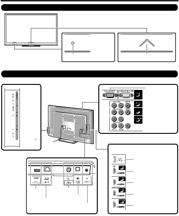
Part Names
TV (Front)
 OPC sensor*
Remote control sensor |
Center Icon illumination |
* OPC: Optical Picture Control
TV (Rear/Side)
*2

 POWER button

 MENU button
 INPUT button


 Channel buttons (CH
 /
/ )
)


 Volume buttons (VOL
 / )
/ )
*1
USB 2 terminal
ETHERNET terminal
*1 External equipment connection *2 Button operations
*3 Details on the Audio Select function
Antenna/
Cable in
DIGITAL AUDIO
OUTPUT terminal
AUDIO IN terminal (shared for PC IN and HDMI 1) *3
*1
RS-232C terminal
 PC IN terminal
 VIDEO 2 terminals


 VIDEO 1 terminals
 COMPONENT terminals
*1

 AUDIO OUT terminal
USB 1 terminal
HDMI 1 terminal
ARC: Audio Return Channel
HDMI 2 terminal
HDMI 3 terminal
HDMI 4 terminal
2 – 1

LC-52/60/70LE640U,C6400U (1st Edition)
Remote Control Unit |
|
1 |
|
|
18 |
|
19 |
2 |
|
3 |
|
4 |
20 |
5 |
21 |
6 |
|
7 |
22 |
8 |
23 |
9 |
24 |
10 |
25 |
11 |
26 |
12 |
|
13 |
27 |
14 |
|
15 |
28 |
|
29 |
16 |
30 |
17 |
|
• When using the remote control unit, point it at the TV.
1 POWER: Switch the TV power on or enter standby.
2TV, STB, DVD.VCR, AUDIO: Switches the remote control for TV, STB, BD, DVD, VCR and AUDIO operation. * To enter the code registration mode, you need to press an appropriate button (STB, DVD VCR or AUDIO) and DISPLAY at the same time.
3External equipment operational buttons: Operate the external equipment.
4OPTION: Display the Link Operation Menu screen. This button will function only when AQUOS LINK is used.
5 SLEEP: Set the sleep timer.
6 0-9: Set the channel.
7(DOT)
8 CC: Display captions from a closed-caption source. 9 AV MODE: Select an audio or video setting.
10MUTE: Mute the sound.
11VOL+/-: Set the volume.
12MENU: Display the menu screen.
13AAL: Display the TV+Web screen.
14 /
/ /
/ /
/ , ENTER: Select a desired item on the screen.
15EXIT: Turn off the menu screen.
16FAVORITE CH: Set the favorite channels.
17A, B, C, D: Select 4 preset favorite channels in 4 different categories.
While watching, you can toggle the selected channels by pressing A, B, C and D.
18DISPLAY: Display the channel information.
19POWER (SOURCE): Turns the power of the external equipment on and off.
20FREEZE: Set the still image. Press again to return to normal screen.
21AUDIO: Selects the MTS/SAP or the audio mode during multichannel audio broadcasts.
22ENT: Jumps to a channel after selecting with the 0-9 buttons.
23FLASHBACK: Return to the previous channel or external input mode.
24VIEW MODE: Select the screen size.
25INPUT: Select a TV input source. (TV, HDMI1, HDMI2, HDMI3, HDMI4, COMPONENT, VIDEO1, VIDEO2, PC IN, Home Network (DLNA), USB)
26 CH / : Select the channel.
27SmartCentral: Display the application window.
28RETURN: Return to the previous menu screen.
29NETFLIX: Display the Netfl ix screen.
30FAV APP 1, 2, 3: You can assign your favorite applications to these buttons.
2 – 2
LC-52/60/70LE640U,C6400U (1st Edition)
QUICK REFERENCE
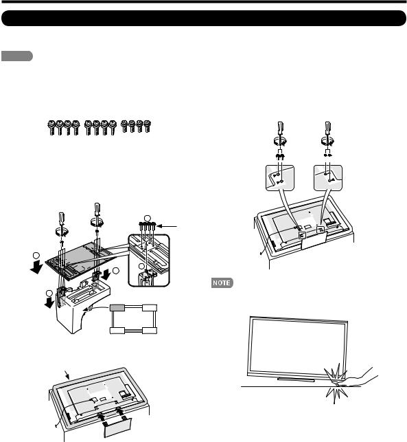
Attaching the Stand
•Before attaching (or detaching) the stand, unplug the AC cord.
•Before performing work spread cushioning over the base area to lay the TV on. This will prevent it from being damaged.
CAUTION
•Attach the stand in the correct direction.
•Do not remove the stand from the TV unless using an optional wall mount bracket to mount it.
•Be sure to follow the instructions. Incorrect installation of the stand may result in the TV falling over.
•After attaching the stand to the TV, do not hold the stand when you put up, set up, move or lay down the TV.
1Confirm that there are 12 screws (8 long screws and 4 short screws) supplied with the stand unit.
2Set the post for the stand unit onto the polystyrene foam.
Attach the base to the post.
Insert and tighten the 8 screws into the 8 holes on the bottom of the base.
•Hold the stand unit securely with one hand, and then tighten the screws.
2
Long |
screws |
2
1
1
4Insert and tighten the 4 screws into the 4 holes on the rear of the TV.


 Short screws
1
FRONT
3Insert the stand into the openings on the bottom of the TV.
•Make sure that the stand is firmly inserted into the TV.
Improper installation may result in tilting of the TV set.
Soft cushion
•To detach the stand, perform the steps in reverse order.
•In the installation procedure, be careful not to catch your fingers between the TV set and the floor.
2 – 3

LC-52/60/70LE640U,C6400U (1st Edition)
CHAPTER 3. DIMENSIONS
[1] DIMENSIONS (LC-52LE640U/C6400U)
LC-52LE640U/LC-52C6400U
47 9/16 (1208)
Unit: inch (mm)
1 3/64 (26.4)*2 |
2 27/32 (72) |
|
|
|
|
5 41/64 |
|
(771) |
|
45 23/64 (1152.0)*1 |
|
(143) |
|
(739) |
|
|
|
||
64 |
|
|
|
||
/ |
32 |
33 |
*1 |
(419) |
|
23 |
3 |
||||
|
/ |
64 |
(648.0) |
|
|
30 |
29 |
1 |
|||
25 |
|||||
|
|
/ |
|
|
|
|
|
|
|
2 |
|
|
|
|
|
/ |
|
|
|
|
|
16 |
21 7/64 (536)
15 3/4 (400)
43/64 (17)
8 15/32 (215) |
11 17/64 (286) 15 3/4 (400)
13 1/8 (333)
4 1/2
(114)
|
(51) |
5° |
64 |
|
/ |
|
1 |
|
2 |
|
(345) |
|
32 |
|
/ |
|
19 |
|
13 |
|
(391) |
|
64 |
|
/ |
|
25 |
|
15 |
6 17/64 |
|
(159) |
|
AN-52AG4
*1
*2
Active area Thinnest part
3 – 1
LC-52/60/70LE640U,C6400U (1st Edition)
[2] DIMENSIONS (LC-60/70LE640U,C6400U)
LC-70LE640U/LC-70C6400U
|
|
63 19/32 (1615) |
|
|
60 19/32 (1538.88)*1 |
(1009) |
(976) |
|
64 |
16 |
*1 |
/ |
/ |
|
39 |
38 |
(865.62) |
47 |
7 |
|
|
|
32 |
|
|
/ |
|
|
3 |
|
|
34 |
|
|
21 7/64 (536) |
|
|
15 3/4 (400) |
|
(115) |
|
|
64 |
|
|
/ |
|
|
34 |
|
|
4 |
|
8 15/32 (215) |
LC-60LE640U/LC-60C6400U
54 17/32 (1385)
2 1/64 (51)*2 |
3 1/2 (89) |
5 23/64
(136)
21 3/16 (538)
13 1/8 (333)
7 31/64 (190)
15 3/4 (400)
5 25/64
(137)
AN-52AG4
1 7/64 (27.9)*2 |
2 59/64 (74) |
|
|
|
|
5 3/4 |
|
52 11/32 (1329.12)*1 |
|
|
(146) |
(872) |
(839) |
|
|
|
32 |
|
|
|
|
/ |
2 |
|
|
|
11 |
/ |
|
*1 |
|
1 |
7 |
(470) |
||
34 |
33 |
29 |
(747.63) |
1 |
|
|
16 |
|
|
|
|
/ |
|
|
|
|
|
|
2 |
|
|
|
|
/ |
|
|
|
|
18 |
Unit: inch (mm)
|
(263) |
|
64 |
|
/ |
5° |
23 |
|
10 |
|
(461) |
|
32 |
|
/ |
|
5 |
|
18 |
|
(512) |
|
64 |
|
/ |
|
11 |
|
20 |
7 59/64 |
|
(201) |
|
21 7/64 (536) |
13 1/8 (333) |
|
(156) |
|
|
||
15 3/4 (400) |
(230) |
5° |
64 |
|
|
6 |
|
|
|
|
/ |
|
|
|
9 |
|
16 |
|
|
|
/ |
|
(395) |
(52) |
1 |
|
|
9 |
|
16 |
|
16 |
(400) |
|
/ |
2 |
|
15 |
|
/ |
|
|
9 |
1 |
|
|
|
|
4 |
|
|
|
/ |
|
|
|
3 |
|
|
|
15 |
|
(442) |
|
|
|
32 |
|
|
|
/ |
|
|
|
13 |
|
|
|
17 |
|
4 17/32 |
6 21/32 |
|
8 15/32 (215) |
(115) |
(169) |
|
AN-52AG4
*1
*2
Active area Thinnest part
3 – 2

LC-52/60/70LE640U,C6400U (1st Edition)
CHAPTER 4. REMOVING OF MAJOR PARTS
[1] REMOVING OF MAJOR PARTS (LC-52LE640U/C6400U)
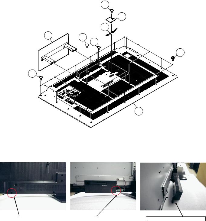
1. Removing of Stand Unit and Rear Cabinet.
1.Remove the 4 lock screws  and detach the Stand Unit
  .
.
2.Remove the 1 lock screw  and detach the AC Cord Cover
  .
.
3.Disconnect AC wire and detach the AC Cord  .
.
4.Remove the 4 VESA Hole Covers  , 11 lock screws
  , 3 lock screws
  and 17 lock screws
  and detach the Rear Cabinet
  .
.
|
3 |
AC Cord Cover 4 |
5 AC Cord |
Stand Unit 2 |
7 |
|
[AC] |
1 |
6 VESA Hole Cover |
|
9 |
|
[AC] |
8
10 Rear Cabinet
[Precaution when removing the rear cabinet]
If the rear cabinet is removed with the set upright, the speakers may fall; it results in connector disconnection. Therefore, never remove the rear cabinet with the set upright.
Be sure to remove the rear cabinet with the screen side down.
|
|
|
|
Speaker fall down. |
Screws for fixing Speaker |
|
Speaker incline. |
|
|
and Rear Cabinet |
|
|
|
|
|
|
|
|
|
[Precaution when mounting the rear cabinet]
Put the speakers in place with the screen side down, and attach the rear cabinet.
Since the speakers are fixed by the rear cabinet, they cannot be fixed without the rear cabinet.
4 – 1

LC-52/60/70LE640U,C6400U (1st Edition)
[Precautions when fixing the Rear Cabinet]
When fixing the Rear Cabinet, be careful not to catch the backlight LED harness, speaker harness and other harnesses in it.
•The hooks on the external wall of the Rear Cabinet are fitted in the Front Cabinet Ass’y. After putting the Rear Cabinet in place, fit the hooks securely; then tighten the screws.
(Work method of Rear Cabinet fixation)
Rear Cabinet (Mat parts)
Front Cabinet Ass'y (Luster parts)
There is a gap without the fingernail fitting in completely only when covering with Rear Cabinet.
It becomes the factor of a gap increase of Front Cabinet Ass'y/Rear Cabinet and the Rear Cabinet misregistration.
Please tighten the screw after Rear Cabinet is firmly pushed, and the fingernail is confirmed.
(Front Cabinet Ass’y/Rear Cabinet fingernail fixation place)
17 places
4 – 2

LC-52/60/70LE640U,C6400U (1st Edition)
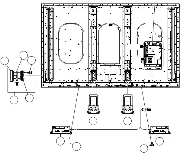
2. Removing of Speaker (L/R), KEY Unit and Fixing Metal Angle.
1.Detach the Bottom Cover 
2.Disconnect the SP wire.
3.Detach the Speaker (L)  , Speaker (R)
  .
.
4.Disconnect the RC wire.
5.Detach the KEY Unit Ass’y  .
.
6.Disconnect the KM wire.
7.Remove the 2 lock screws  and detach the Key Button
  from Key Button Cover
  .
.
8.Detach the KEY Unit  from Key Button
  .
.
9.Remove the 19 lock screws  and detach the Fixing Metal Angle
  .
.
MAIN Unit
KEY Unit Ass'y |
4 |
|
|
|
|
[SP] |
|
KEY Unit |
7 |
5 |
|
|
|
[RC] |
|
Key Button 8 |
[KM] |
||
Cover |
|||
|
|
||
Key Button |
6 |
||
Fixing 10
Metal
Angle
9
Bottom 1
[SP]
Cover
Speaker (R) 3 |
Speaker (L) 2 |
4 – 3

LC-52/60/70LE640U,C6400U (1st Edition)
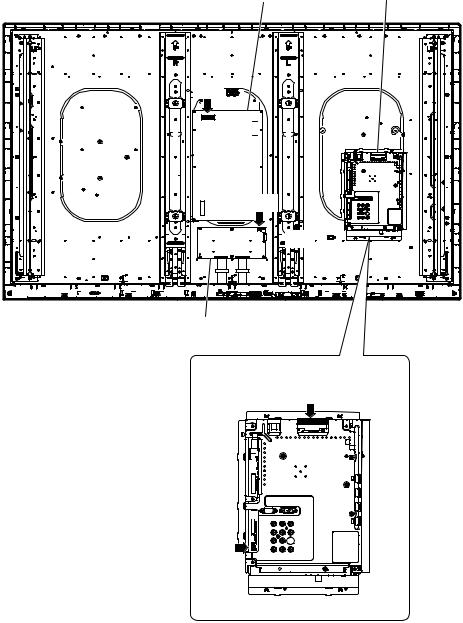
3. Removing of Connectors
1.Disconnect the following connectors from the MAIN Unit. (PD, LV, PL, Cl, UB)
2.Disconnect the following connectors from the POWER/DRIVE Unit. (PD, LA)
3.Disconnect the following connectors from the LCD CONTROL Unit. (LW, PL)
POWER/DRIVE Unit MAIN Unit
[LA]
[LA]
[PD]

[PL]
[LW]

LCD CONTROL Unit
MAIN Unit
[PD]
[LV] 

[PL]
[CI] 
 [UB]
[UB]
4 – 4

LC-52/60/70LE640U,C6400U (1st Edition)
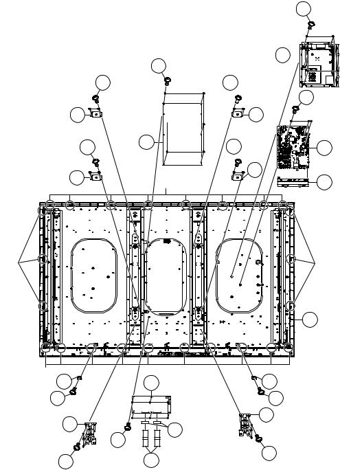
4. Removing of 60” LCD Panel Module Unit, LCD CONTROL Unit, MAIN Unit, POWER/DRIVE Unit.
1.Remove the 8 lock screws  .
.
2.Detach the 14 Fixing Metal Angles  .
.
3.Remove the 8 Hooks and detach the 60” LCD Panel Module Unit  .
.
4.Remove the 2 Connecting Cords  , 2 Ferrite Cores
  and 6 lock screws
  and detach the LCD CONTROL Unit
  .
.
5.Remove the 5 lock screws  and detach the Shield (MAIN Unit)
  .
.
6.Remove the 3 lock screws  and detach the MAIN Unit
  and Terminal Angle (Bottom)
  .
.
7.Remove the 6 lock screws  and detach the POWER/DRIVE Unit
  and AC Cord Barrier
  .
.
8.Remove the 8 lock screws  and detach the 2 Center Angles
  .
.
|
Shield |
|
|
|
(MAIN Unit) |
9 |
|
POWER/DRIVE Unit |
Terminal Angle 10 |
|
|
(Bottom) |
|
||
14 |
8 |
||
|
|||
|
|
||
13 |
11 |
|
|
|
|
||
|
MAIN Unit 12 |
|
|
AC Cord Barrier 15 |
|
|
|
Fixing Metal 2 |
2 Fixing Metal |
2 Fixing Metal |
|
Angle |
Angle |
Angle |
Fixing Metal 2 |
2 Fixing Metal |
Angle |
Angle |
3 60" LCD Panel
Module Unit
Hook |
Hook |
|
1 |
1 |
|
|
6 |
|
|
|
||
|
16 |
Ferrite Core 5 |
7 |
LCD CONTROL Unit |
16 |
|
|||
|
|
|
||
|
|
|
|
|
|
|
4 Connecting |
|
|
|
|
|
Cord |
|
Center |
|
|
|
|
Angle |
|
|
|
|
17 |
|
|
|
|
1 |
1 |
17 Center |
|
|
Angle |
|
|
||
|
|
|
|
|
4 – 5

LC-52/60/70LE640U,C6400U (1st Edition)
5. Removing of R/C OPC Unit, ICON Unit, WiFi Unit.
1.Detach the R/C OPC Unit  .
.
2.Disconnect the RA wire.
3.Remove the 1 lock screw  and detach the ICON Unit
  .
.
4.Disconnect the CI wire.
5.Detach the WiFi Unit  .
.
6.Disconnect the UB wire.
Front Cabinet Ass'y
[RA] |
[CI] |
[UB] |
R/C OPC Unit 1 |
ICON Unit 3 |
4 WiFi |
|
2 |
Unit |
4 – 6

LC-52/60/70LE640U,C6400U (1st Edition)
[2] REMOVING OF MAJOR PARTS (LC-60LE640U/C6400U)
1. Removing of Stand Unit and Rear Cabinet.
1.Remove the 4 lock screws  and detach the Stand Unit
  .
.
2.Remove the 1 lock screw  and detach the AC Cord Cover
  .
.
3.Disconnect AC wire and detach the AC Cord  .
.
4.Remove the 4 VESA Hole Covers  , 11 lock screws
  , 20 lock screws
  and detach the Rear Cabinet
  .
.
|
|
|
|
|
|
|
|
|
|
|
|
|
|
|
|
|
|
|
|
|
|
|
|
|
|
|
|
|
|
|
|
|
|
|
|
|
|
|
|
|
|
[Precaution when removing the rear cabinet]
If the rear cabinet is removed with the set upright, the speakers may fall; it results in connector disconnection. Therefore, never remove the rear cabinet with the set upright.
Be sure to remove the rear cabinet with the screen side down.
|
|
|
|
Speaker fall down. |
Screws for fixing Speaker |
|
Speaker incline. |
|
|
and Rear Cabinet |
|
|
|
|
|
|
|
|
|
[Precaution when mounting the rear cabinet]
Put the speakers in place with the screen side down, and attach the rear cabinet.
Since the speakers are fixed by the rear cabinet, they cannot be fixed without the rear cabinet.
4 – 7
LC-52/60/70LE640U,C6400U (1st Edition)
[Precautions when fixing the Rear Cabinet]
When fixing the Rear Cabinet, be careful not to catch the backlight LED harness, speaker harness and other harnesses in it.
•The hooks on the external wall of the Rear Cabinet are fitted in the Front Cabinet Ass’y. After putting the Rear Cabinet in place, fit the hooks securely; then tighten the screws.
(Work method of Rear Cabinet fixation)
Rear Cabinet (Mat parts)
Front Cabinet Ass'y (Luster parts)
There is a gap without the fingernail fitting in completely only when covering with Rear Cabinet.
It becomes the factor of a gap increase of Front Cabinet Ass'y/Rear Cabinet and the Rear Cabinet misregistration.
Please tighten the screw after Rear Cabinet is firmly pushed, and the fingernail is confirmed.
(Front Cabinet Ass’y/Rear Cabinet fingernail fixation place)
17 places
4 – 8

LC-52/60/70LE640U,C6400U (1st Edition)
2. Removing of Speaker (L/R), KEY Unit and Fixing Metal Angle.
1.Detach the Speaker (L)  , Speaker (R)
  .
.
2.Disconnect the SP wire.
3.Disconnect the RC wire.
4.Detach the KEY Unit Ass’y  .
.
5.Disconnect the KM wire.
6.Remove the 2 lock screws  and detach the Key Button
  from Key Button Cover
  .
.
7.Detach the KEY Unit  from Key Button
  .
.
8.Remove the 4 Hooks and detach the 2 Bottom Cover  .
.
|
|
||
|
|
||
|
|||
|
|
|
|
|
|
|
|
|
|
|
|
|
|
|
|


|
|
|
|
4 – 9
LC-52/60/70LE640U,C6400U (1st Edition)
3. Removing of Connectors
1.Disconnect the following connectors from the MAIN Unit. (PD, LV, PL, Cl, UB)
2.Disconnect the following connectors from the POWER/DRIVE Unit. (PD, LA)
3.Disconnect the following connectors from the LCD CONTROL Unit. (LV, PL)
䎾䎯䎤䏀


4 – 10

LC-52/60/70LE640U,C6400U (1st Edition)
4. Removing of 60” LCD Panel Module Unit, LCD CONTROL Unit, MAIN Unit, POWER/DRIVE Unit.
1.Remove the 21 Hooks and detach the 60” LCD Panel Module Unit  .
.
2.Remove the 2 Connecting Cords  , 2 Ferrite Cores
  and 6 lock screws
  and detach the LCD CONTROL Unit
  .
.
3.Remove the 5 lock screws  and detach the MAIN PWB Shield
  .
.
4.Remove the 3 lock screws  and detach the MAIN Unit
  and Terminal Angle (Bottom)
  .
.
5.Remove the 6 lock screws  and detach the POWER/DRIVE Unit
  and AC Cord Barrier
  .
.
6.Remove the 12 lock screws  and detach the 2 Support Ass’y
  .
.
7.Remove the 16 lock screws  and detach the 4 VESA Angle Ass’
  .
.
|
|
|
|
|
|
|
|
|
|
|
|
|
|
|
|
|
|
|
|
|
|
|
|
|
|
|
|
|
|
|
|
|
|
||
|
|
|
|
|
|
|
|
|
|
|
|
|
|
|
|||
|
|
|
|
|
|
|||
|
|
|
|
|
|
|
||
|
|
|
|
|
|
|
|
|
|
|
|
|
|
|
|
||
|
|
|
|
|
|
|
|
|
|
|
|
|
|
|
|
|
|
|
|
|
|
|
|
|
|
|
|
|
|
|
|
|
|
||
|
|
|
|
|
|
|
|
|
|
|
|
|
|
|
|
|
|
|
|
|
|
|
|
|
|
|
|
|
|
|
|
|
|
||
|
|
|
|
|
|
|
|
|
|
|
|
|
|
|
|
|
|
|
|
|
|
|
|
|
||
|
|
|
|
|
|
|||
|
|
|
|
|
|
|
||
|
|
|
|
|
|
|
|
|
|
|
|
|
|
|
|
|
|
|
|
|
|
|
|
|
|
|
|
|
|
|
|
|
|
|
|
|
||||
|
|
|
|
|
|
|
|
|
|
|
|
|
|
|
|
|
|
|
||
|
|
|
|
|
|
|
|
|
|
|
|
|
|
4 – 11
LC-52/60/70LE640U,C6400U (1st Edition)
5. Removing of R/C OPC Unit, ICON Unit, WiFi Unit.
1.Detach the R/C OPC Unit  .
.
2.Disconnect the RA wire.
3.Detach the ICON Unit  .
.
4.Disconnect the CI wire.
5.Detach the Wi-Fi Unit  .
.
6.Disconnect the UB wire.
|
|
|
|
|
|
|
|
|
|
|
|
4 – 12
LC-52/60/70LE640U,C6400U (1st Edition)
[3] REMOVING OF MAJOR PARTS (LC-70LE640U/C6400U)
1. Removing of Stand Unit and Rear Cabinet Ass’y.
1.Remove the 4 lock screws  and detach the Stand Unit
  .
.
2.Remove the 1 lock screw  and detach the AC Cord Cover
  .
.
3.Disconnect AC wire and detach the AC Cord  .
.
4.Remove the 4 VESA Hole Covers  , 9 lock screws
  and 21 lock screws
  and detach the Rear Cabinet Ass’y
  .
.
|
|
|
|
|
|
|
|
|
|
|
|
|
|
|
|
|
|
|
|
|
|
|
|
|
|
|
|
|
|
|
|
|
|
|
|
|
|
|
|||
|
|
|
|
||
|
|
|
|
|
|
[Precautions when mounting and removing the rear cabinet]
Basically, there is no problem as in LC-60LE632U. However, the screws on both sides are not tightened together with the Rear Cabinet Ass’y. The inside is fixed by the module and Speaker.
Therefore, it does not come away completely, but only one side can come off.
Tighten together with the |
|
Fix with the 70" LCD Panel Module Unit. |
Rear Cabinet Ass'y. |
|
|
|
|
|
Only one side (outer) can come off.
4 – 13

LC-52/60/70LE640U,C6400U (1st Edition)
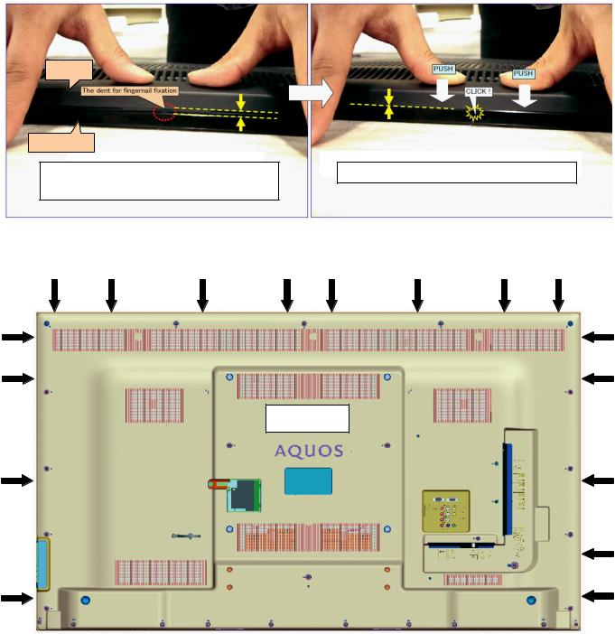
[Precautions for assembly]
Push |
Push |
Push |
CAUTION
Set it so that there may not be a clearance between Front Cabinet Ass'y and Rear Cabinet Ass'y.
Push |
|
Push |
There is a gap without the fingernail fitting |
|
The fingernail is surely fixed when Rear cabinet Ass'y is |
in completely only when covering with Rear Cabinet Ass'y. |
|
firmly pushed, and the gap disappears. |
|
|
|
Push |
Push |
Push |
(Front Cabinet Ass’y/Rear Cabinet Ass’y fingernail fixation place)
19 places
4 – 14
LC-52/60/70LE640U,C6400U (1st Edition)
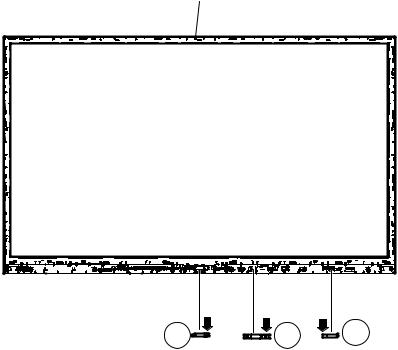
2. Removing of Speaker (L/R) and KEY Unit.
1.Disconnect the SP wire.
2.Remove the 2 lock screws  and detach the Speaker (L)
  , Speaker (R)
  .
.
3.Disconnect the RC wire.
4.Detach the KEY Unit Ass’y  .
.
5.Disconnect the KM wire.
6.Remove the 2 lock screws  and detach the Key Button
  from Key Button Cover
  .
.
7.Detach the KEY Unit  from Key Button
  .
.
8.Remove the 4 Hooks and detach the 2 Bottom Cover  .
.
|
|
||
|
|||
|
|
|
|
|
|
||
|
|||
|
|
|
|
|
|||
|
|
|
|
|
|
|
|

4 – 15
LC-52/60/70LE640U,C6400U (1st Edition)
3. Removing of Connectors
1.Disconnect the following connectors from the MAIN Unit. (PD, LV, PL, Cl, UB)
2.Disconnect the following connectors from the POWER/DRIVE Unit. (PD, LA)
3.Disconnect the following connectors from the LCD CONTROL Unit. (LV, PL)
䎾䎯䎤䏀


4 – 16
LC-52/60/70LE640U,C6400U (1st Edition)
4. Removing of 70” LCD Panel Module Unit, LCD CONTROL Unit, MAIN Unit, POWER Unit.
1.Remove the 24 Hooks and detach the 70” LCD Panel Module Unit  .
.
2.Remove the 2 Connecting Cords  , 2 Ferrite Cores
  , 6 lock screws
  and detach the LCD CONTROL Unit
  .
.
3.Remove the 2 look screws  and detach the 2 Spacers
  .
.
4.Remove the 6 lock screws  and detach the POWER Unit
  .
.
5.Remove the 5 lock screws  and detach the MAIN PWB Shield
  .
.
6.Remove the 3 lock screws  and detach the MAIN Unit
  and Terminal Angle (Bottom)
  .
.
7.Remove the 12 lock screws  and detach the 2 Support Ass’y
  .
.
8.Remove the 16 lock screws  and detach the 4 VESA Angle Ass’ys
  .
.


|


|

|
|
|
|
|
|
|
|||
|
|
|||
|
|
|
|
|
|
|
|
|
|
|
|
|
|
|
|
|
|
|||
|
|
|
|
|
|
|
|
|
|
|
|
|
||
|
|
|
|
|
|
|
|
|
|
|
|
|
|
|
|
|
|
|
|
|
|
|
|
|
4 – 17
 Loading...