


 Loading...
LC-46XL1E
LC-46XL1S
LC-52XL1E
LC-52XL1S
LCD COLOUR TELEVISION LCD-FARBFERNSEHGERÄT TÉLÉVISION COULEUR À ÉCRAN
À CRISTAUX LIQUIDES (LCD) TELEVISORE A COLORI LCD LCD-KLEURENTELEVISIE TELEVISIÓN EN COLOR LCD
OPERATION MANUAL BEDIENUNGSANLEITUNG MODE D'EMPLOI MANUALE DI ISTRUZIONI GEBRUIKSAANWIJZING MANUAL DE MANEJO
ESPAÑOL NEDERLANDS ITALIANO FRANÇAIS DEUTSCH ENGLISH

SPECIAL NOTE FOR USERS IN THE U.K.
The mains lead of this product is fi tted with a non-rewireable (moulded) plug incorporating a 13A fuse. Should the fuse need to be replaced, a BSI or ASTA approved BS 1362 fuse marked  or ASA and of the same rating as above, which is also indicated on the pin face of the plug, must be used.
Always refi t the fuse cover after replacing the fuse. Never use the plug without the fuse cover fi tted.
In the unlikely event of the socket outlet in your home not being compatible with the plug supplied, cut off the mains plug and fi t an appropriate type.
DANGER:
The fuse from the cut-off plug should be removed and the cut-off plug destroyed immediately and disposed of in a safe manner.
Under no circumstances should the cut-off plug be inserted elsewhere into a 13A socket outlet, as a serious electric shock may occur.
To fi t an appropriate plug to the mains lead, follow the instructions below:
IMPORTANT:
The wires in the mains lead are coloured in accordance with the following code:
Blue: Neutral
Brown: Live
As the colours of the wires in the mains lead of this product may not correspond with the coloured markings identifying the terminals in your plug, proceed as follows:
•The wire which is coloured blue must be connected to the plug terminal which is marked N or coloured black.
•The wire which is coloured brown must be connected to the plug terminal which is marked L or coloured red. Ensure that neither the brown nor the blue wire is connected to the earth terminal in your three-pin plug. Before replacing the plug cover make sure that:
•If the new fi tted plug contains a fuse, its value is the same as that removed from the cut-off plug.
•The cord grip is clamped over the sheath of the mains lead, and not simply over the lead wires.
IF YOU HAVE ANY DOUBT, CONSULT A QUALIFIED ELECTRICIAN.

OPERATION MANUAL |
ENGLISH |
|
|
•The illustrations and on-screen displays in this operation manual are for explanation purposes and may vary slightly from the actual operations.
•The examples used throughout this manual are based on the LC-52XL1E model.
Contents
Contents......................................................................................... |
1 |
Dear SHARP customer.................................................................. |
2 |
Important Safety Precautions ...................................................... |
2 |
Trademarks.................................................................................... |
2 |
Supplied accessories .................................................................... |
3 |
Quick guide .................................................................................... |
3 |
Attaching the stand................................................................... |
3 |
Setting the TV ........................................................................... |
4 |
TV (Front view) ......................................................................... |
5 |
TV (Rear view) .......................................................................... |
5 |
Inserting the batteries................................................................ |
6 |
Using the remote control unit .................................................... |
6 |
Cautions regarding the remote control unit .......................... |
6 |
Remote control unit .................................................................. |
7 |
Turning on the power................................................................ |
8 |
Standby mode .......................................................................... |
8 |
Initial auto installation (Analogue) ............................................... |
8 |
Initial auto installation (DTV)....................................................... |
8 |
Channel selection using the station list (Analogue)..................... |
9 |
Using 7on the remote control unit................................... |
9 |
Using external equipment........................................................... |
10 |
Connecting a VCR ................................................................. |
10 |
Connecting a game console or camcorder.............................. |
10 |
Connecting a DVD player........................................................ |
10 |
Connecting a decoder ............................................................ |
11 |
Connecting a PC .................................................................... |
11 |
HDMI connection .................................................................... |
11 |
Controlling HDMI device using AQUOS LINK .......................... |
12 |
Connecting HDMI device to TV ............................................... |
12 |
AQUOS LINK Auto Power On ....................................... |
13 |
Operating AQUOS LINK device.......................................... |
13 |
Listening with AQUOS Audio speaker system ............... |
13 |
Manually changing AQUOS Audio speaker system’s sound mode ............. |
13 |
Playback of titles using AQUOS LINK ........................... |
14 |
Selecting media type for CEC-compatible recorder............. |
14 |
HDMI device selection .................................................. |
14 |
Recording via AQUOS Recorder EPG (only for recorder) ............. |
14 |
Using AV Link function ............................................................ |
14 |
Menu operations.......................................................................... |
15 |
On-Screen Display.................................................................. |
15 |
Common operations ............................................................... |
15 |
Menu operation without a remote control................................ |
15 |
Picture menu .......................................................................... |
16 |
Backlight ...................................................................... |
16 |
Contrast ....................................................................... |
16 |
Brightness .................................................................... |
16 |
Colour .......................................................................... |
16 |
Tint ............................................................................... |
16 |
Sharpness .................................................................... |
16 |
Red .............................................................................. |
16 |
Green ........................................................................... |
16 |
Blue.............................................................................. |
16 |
Colour temp. ................................................................ |
16 |
Black ............................................................................ |
16 |
3D-Y/C ......................................................................... |
16 |
DNR (Digital Noise Reduction)....................................... |
16 |
I/P setting ..................................................................... |
16 |
Film mode..................................................................... |
17 |
truD(R) .......................................................................... |
17 |
100Hz........................................................................... |
17 |
Reset............................................................................ |
17 |
Sound menu ........................................................................... |
17 |
Treble ........................................................................... |
17 |
Bass ............................................................................. |
17 |
Loudness...................................................................... |
17 |
Auto volume ................................................................. |
17 |
Balance ........................................................................ |
17 |
Clear voice.................................................................... |
17 |
Reset............................................................................ |
17 |
Connections menu.................................................................. |
18 |
Decoder ....................................................................... |
18 |
Input select................................................................... |
18 |
HDMI setup .................................................................. |
18 |
Supply voltage.............................................................. |
19 |
AV-Link (EXT 2 only) ..................................................... |
19 |
Miscellaneous............................................................... |
19 |
Setup menu ............................................................................ |
19 |
AQUOS LINK Auto Power On ....................................... |
19 |
Channels ...................................................................... |
19 |
Child lock...................................................................... |
20 |
Auto format .................................................................. |
20 |
Language ..................................................................... |
20 |
Blue illumination setting ................................................ |
20 |
Factory settings ............................................................ |
20 |
Miscellaneous............................................................... |
21 |
Geometry menu...................................................................... |
21 |
Picture horizontal .......................................................... |
21 |
Picture vertical .............................................................. |
21 |
Phase position.............................................................. |
21 |
Other menu items ................................................................... |
22 |
AV mode ........................................................................... |
22 |
Status display .................................................................... |
22 |
INPUT SOURCE ................................................................ |
22 |
Still image .......................................................................... |
22 |
OPC .................................................................................. |
22 |
Wide modes ...................................................................... |
23 |
Analogue teletext .................................................................... |
24 |
Using analogue teletext menu ............................................ |
24 |
Newsfl ash..................................................................... |
24 |
Reveal/Conceal ............................................................ |
24 |
Setup............................................................................ |
25 |
DTV menu operations ................................................................. |
26 |
DTV menu operation buttons .................................................. |
26 |
DTV On-Screen Display .......................................................... |
26 |
DTV common operations ........................................................ |
26 |
About using the character set screen................................. |
27 |
Language................................................................................ |
27 |
Programme Setup .................................................................. |
27 |
Favourite....................................................................... |
28 |
Lock ............................................................................. |
28 |
Move ............................................................................ |
28 |
Move To ....................................................................... |
28 |
Skip.............................................................................. |
28 |
Select ........................................................................... |
29 |
Erase ............................................................................ |
29 |
Label ............................................................................ |
29 |
View ............................................................................. |
29 |
Installation............................................................................... |
29 |
Auto Installation ................................................................. |
29 |
Carrier Scan....................................................................... |
29 |
Carrier Setup ..................................................................... |
30 |
System Setup ......................................................................... |
30 |
OSD Setup ........................................................................ |
30 |
Child Lock ......................................................................... |
31 |
Accessories ............................................................................ |
31 |
Software Version................................................................ |
31 |
Software Upgrade.............................................................. |
31 |
Common Interface .................................................................. |
32 |
Inserting a CA card ............................................................ |
32 |
Supplying power to the antenna.............................................. |
32 |
About EPG.............................................................................. |
33 |
Using the EPG ................................................................... |
33 |
Using the EPG Timer ......................................................... |
33 |
Using the digital programme list .............................................. |
34 |
Viewing a service banner......................................................... |
34 |
Using the multi audio function ................................................. |
35 |
Displaying subtitles ................................................................. |
35 |
Using the MHEG5 application (UK only) .................................. |
35 |
Appendix ...................................................................................... |
36 |
Troubleshooting...................................................................... |
36 |
Using universal remote control ................................................ |
37 |
PC compatibility chart............................................................. |
41 |
RS-232C port specifi cations ................................................... |
41 |
Specifi cations ......................................................................... |
43 |
Optional accessories............................................................... |
43 |
End of life disposal.................................................................. |
44 |
ENGLISH

 1
1
Dear SHARP customer
Thank you for your purchase of the SHARP LCD colour TV product. To ensure safety and many years of troublefree operation of your product, please read the Important Safety Precautions carefully before using this product.
Important Safety Precautions
•Cleaning—Unplug the AC cord from the AC outlet before cleaning the product. Use a damp cloth to clean the product. Do not use liquid cleaners or aerosol cleaners.
•Water and moisture—Do not use the product near water, such as bathtub, washbasin, kitchen sink, laundry tub, swimming pool and in a wet basement.
• Do not place vases or any other water-fi lled containers on this product. The water may spill onto the product causing fi re or electric shock.
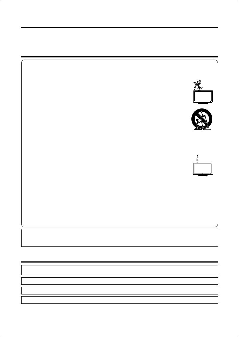
• Stand—Do not place the product on an unstable cart, stand, tripod or table. Doing so can cause the product to fall, resulting in serious personal injuries as well as damage to the product. Use only a cart, stand, tripod, bracket or table recommended by the manufacturer or sold with the product.
When mounting the product on a wall, be sure to follow the manufacturer’s instructions. Use only the mounting hardware recommended by the manufacturer.
•When relocating the product placed on a cart, it must be moved with utmost care. Sudden stops, excessive force and uneven fl oor surface can cause the product to fall from the cart.
• Ventilation—The vents and other openings in the cabinet are designed for ventilation. Do not cover or block these vents and openings since insuffi cient ventilation can cause overheating and/or shorten the life of the product. Do not place the product on a bed, sofa, rug or other similar surface, since they can block ventilation openings. This product is not designed for built-in installation; do not place the product in an enclosed place such as a bookcase or rack, unless proper ventilation is provided or the manufacturer’s instructions are followed.
•The LCD panel used in this product is made of glass. Therefore, it can break when the product is dropped or impact applied. If the LCD panel is broken, be careful not to be injured by broken glass.
•Heat sources—Keep the product away from heat sources such as radiators, heaters, stoves and other heat-generating
products (including amplifi ers).
• To prevent fi re, never place any type of candle or naked fl ames on the top or near the TV set.
• To prevent fi re or shock hazard, do not place the AC cord under the TV set or other heavy items.
• Do not display a still picture for a long time, as this could cause an afterimage to remain.
•There is power consumption always if main plug is connected.
•Servicing—Do not attempt to service the product yourself. Removing covers can expose you to high
voltage and other dangerous conditions. Request a qualifi ed person to perform servicing.
The LCD panel is a very high technology product, giving you fi ne picture details.
Due to the very large number of pixels, occasionally a few non-active pixels may appear on the screen as a fi xed point of blue, green or red.
This is within product specifi cations and does not constitute a fault.
Precautions when transporting the TV
When transporting the TV, never carry it by holding onto the speakers. Be sure to always carry the TV by two people holding it with two hands — one hand on each side of the TV.
WARNING:
This is a Class A product. In a domestic environment this product may cause radio interference in which case the user may be required to take adequate measures.
Trademarks
•“HDMI, the HDMI logo and High-Defi nition Multimedia Interface are trademarks or registered trademarks of HDMI Licensing LLC.”
•truD is a registered trademark of Micronas in Germany and other countries.
•The “HD ready” Logo is a trademark of EICTA.
•The DVB logo is the registered trademark of the Digital Video Broadcasting - DVB - project.
 2
2

Supplied accessories
AC cord (g1) |
Cable tie (g1) |
Stand unit |
Cable clamp |
3 RCA to 15-pin |
|
(For Europe, except |
(For U.K. and Eire) |
|
(g1) |
(Smallg2, Large g1) |
D-sub adapter |
|
|
|
(g1) |
||
U.K. and Eire) |
|
|
|
|
|
|
|
|
|
|
|
U.K. type 3-pin AC cord is only included with models LC-46XL1E,
LC-52XL1E.
Page 4 Page 4 Page 3 Page 4 Page 10
•“AAA” size battery (g2)..........Page 6 • Remote control unit (g1)..........Pages 6 and 7
•Operation manual (This publication)
Quick guide
Attaching the stand
Before performing work spread cushioning over the base area to lay the TV on, making sure the area is completely flat. This will prevent it from being damaged.
Before attaching (or detaching) stand, unplug the AC cord from the AC INPUT terminal.
CAUTION
•Attach the stand in the correct direction.
•Be sure to follow the instructions. Incorrect installation of the stand may result in the TV falling over.
1Confirm that there are 10 screws (6 short screws and 4 long screws) supplied with the TV.
2Attach the two supporting posts for the stand unit onto the base using the box for the stand unit as shown below.
(Close-up of the upper side of the stand unit)
key
Short screw 
1Insert each of the protrusions on the two supporting posts into the openings on the upper side of the base.
2Insert and tighten the 6 short screws with the hex key (supplied with the product) in the order of 1, 2 and 3.
31Insert the stand into the openings on the bottom of the TV.
2Insert and tighten the 4 long screws into the 4 holes on the rear of the TV.
Hex key


 Long screw
Soft cushion
NOTE
•To detach the stand, perform the above steps in reverse order.
 3
3
Quick guide
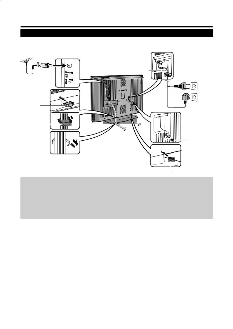
Setting the TV
Standard DIN45325 plug (IEC 169-2)
75 q coaxial cable
Cable clamp (large)
Bundle the cables with the clamp.
Cable tie 

Place the TV close to the AC outlet, and keep the power plug within reach.
Ferrite Core * 
(For Europe, except U.K. and Eire)
AC cord
(For U.K. and
Eire)
Bundle the AC cord with the clamp (small).
Cable clamp (small)
Antenna
Connect the antenna cable from your antenna-/cable socket or the (room-/roof) antenna for antenna input terminal on the back of your TV set to receive digitally/terrestrially broadcast stations.
An indoor antenna can also be used under good reception conditions. Passive and active room antennas are offered commercially. In an active antenna its power is supplied via the antenna input terminal.
The supply voltage (5V) must be correspondingly set under “Supply voltage”. (Page 19)
* Ferrite Core
The Ferrite Core should be permanently attached and never removed from the AC cord.
Setting the TV on the wall
•This TV should be mounted on the wall only with the wall mount bracket available from SHARP. (See page 43.) The use of other wall mount brackets may result in an unstable installation and may cause serious injuries.
•Installing the LCD Colour TV requires special skill that should only be performed by qualified service personnel. Customers should not attempt to do the work themselves. SHARP bears no responsibility for improper mounting or mounting that results in accident or injury.
•You can ask a qualifi ed service personnel about using an optional bracket to mount the TV to the wall.
 4
4
Quick guide
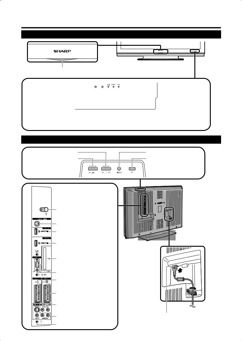
TV (Front view)
Blue illumination LED indicator
|
|
|
|
|
|
|
|
|
|
|
|
|
|
|
|
|
|
|
|
|
|
|
|
|
|
|
|
|
|
|
|
|
|
|
|
|
|
|
|
|
|
Remote control |
|
|
|
|
|
|
|
|
|
OPC indicator |
|||
|
|
|
|
|
|
|
|
|
|
|
|
|
|
sensor |
|
|
|
|
|
|
|
|
|||||
|
|
|
|
|
|
|
|
|
|||||
OPC sensor |
|
|
|
|
|
|
|
|
|
|
SLEEP indicator |
||
|
|
|
|
|
|
|
|
|
|
||||
|
|
|
|
|
|
|
|
|
|
|
|
|
B(Standby/On) |
|
|
|
|
|
|
|
|
|
|
|
|
|
indicator |
|
|
|
|
|
|
|
|
|
|
|
|||
TV (Rear view)
P (s/r) (Programme [channel] buttons) i(l/k)
(Volume buttons)
Antenna input terminal (DVB-T 5V=/80 mA)
RS-232C terminal
EXT 6 (HDMI) terminal
EXT 5 (HDMI/AUDIO) terminals
COMMON INTERFACE slot
EXT 4 terminals
EXT 1 (RGB) terminal
MENU button
a(Power button)
NOTE
•Only if you use an active terrestrial
antenna, select “yes (5V)” under “Supply voltage”. (Page 19)
EXT 2 (AV) terminal
OUTPUT (Audio) terminals
EXT 3 terminals |
AC INPUT terminal |
Headphone jack
 5
5
Quick guide
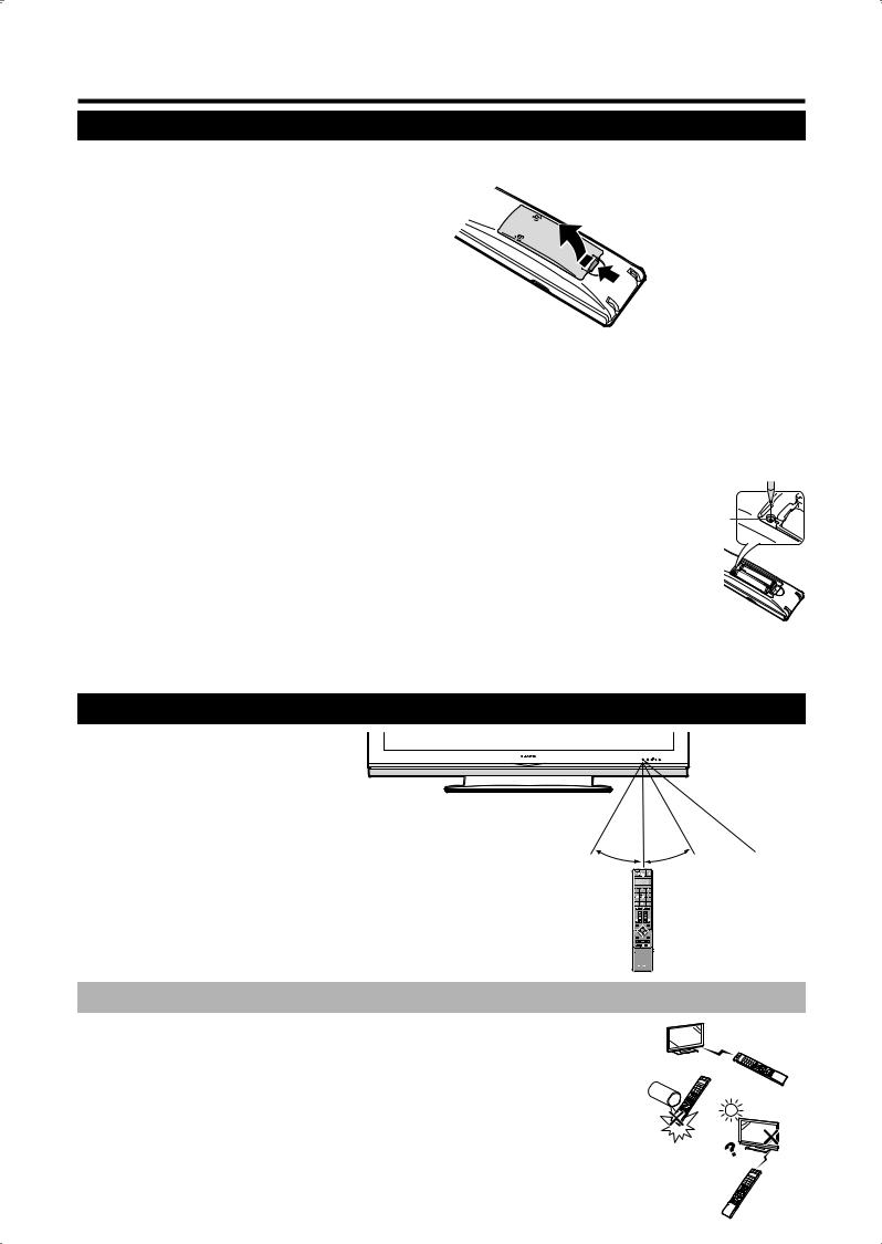
Inserting the batteries
Before using the TV for the fi rst time, insert two “AAA” size batteries (supplied). When the batteries become depleted and the remote control unit fails to operate, replace the batteries with new “AAA” size batteries.
1
2
3
Press and slide the battery cover to open it.
Insert two supplied “AAA” size batteries.
•Place batteries with their terminals corresponding to the (e) and (f) indications in the battery compartment.
Close the battery cover.
CAUTION
Improper use of batteries can result in chemical leakage or explosion. Be sure to follow the instructions below.
•Do not mix batteries of different types. Different types of batteries have different characteristics.
•Do not mix old and new batteries. Mixing old and new batteries can shorten the life of new batteries or cause chemical leakage in old batteries.
•Remove batteries as soon as they have worn out. Chemicals that leak from batteries can cause a rash. If you fi nd any chemical leakage, wipe thoroughly with a cloth.
•When replacing the batteries, use alkaline batteries instead of manganese ones.
•Do not overuse the light-up function by using LIGHT Dbutton, doing so may shorten the battery life. Replace the batteries when the light on LCD window or light-up function become weak or blurry.
• Do not continue to use the remote control unit with batteries running low. This may result in error message or malfunction. Should this happen replace the batteries and leave it unused for a while. Otherwise, you may open the rear battery cover and press the RESET button. When you press the RESET button, your Universal remote control settings will be deleted.
• The remote control unit has a internal memory of external devices. In order not to lose the data, replace the batteries quickly. If the manufacturer code is initialised and lost, you can input the manufacturer code again. (See page 37.)
•The batteries supplied with this product may have a shorter life expectancy due to storage conditions.
•If you will not be using the remote control unit for an extended period of time, remove the batteries from it.
Using the remote control unit
Use the remote control unit by pointing it towards the remote control sensor. Objects between the remote control unit and sensor may prevent proper operation.
|
5 m |
|
|
30° |
30° |
Remote control |
|
sensor |
|||
|
|
Cautions regarding the remote control unit
• Do not expose the remote control unit to shock.
In addition, do not expose the remote control unit to liquids, and do not place in an area with high humidity.
• Do not install or place the remote control unit under direct sunlight. The heat may cause deformation of the unit.
• The remote control unit may not work properly if the remote control sensor of the TV is under direct sunlight or strong lighting. In such case, change the angle of the lighting or TV, or operate the remote control unit closer to the remote control sensor.
 6
6
Quick guide
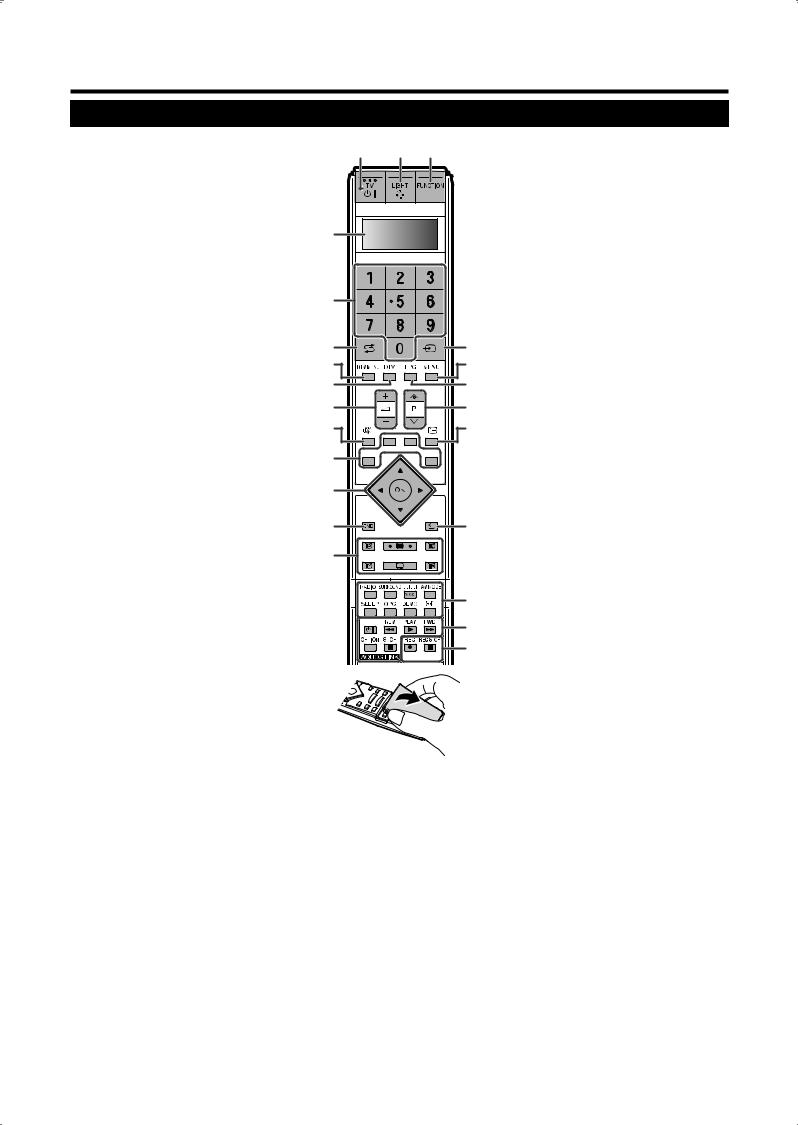
Remote control unit
NOTE
•The symbols 8, 9and 0 indicate that the buttons become available in respective operating mode when using as a universal remote control.
1B(TV Standby/On) 890
(Page 8)
2LIGHT D890
When pressed buttons that are frequently used (P r/s, ik/l, 0 - 9 numeric buttons, Aand b) will light. The lighting will turn off if
no operations are performed within about 5 seconds. This button is used for performing operations in low-light situations.
3FUNCTION 890
Press this button briefl y (for more than 0.2 second), and the remote control switches for DVD, SetTopBox or VCR operation and currently controlled device will be indicated in the LCD window. See page 37 for how to use this unit as a universal remote control.
4LCD window 890
This screen shows which device you are currently controlling. (TV, DVD, STB or VCR).
50 – 9 9
Set the channel in TV and DTV mode. Enter the desired numbers or letters. Set the page in Teletext mode.
6A(Flashback)
Press to return to the previous image in normal viewing mode.
7DTV MENU
DTV: Display DTV Menu screen.
8DTV
Press to access DTV mode while watching other input sources, and vice versa.
(Will not work if you were watching DTV immediately before turning off the TV. In this case fi rst select any other input source except DTV using the b button.)
9i(k/l) (Volume) 890
Increase/decrease TV volume.
10e(Mute) 890
TV sound on/off
11Colour (Red/Green/Yellow/Blue)
TELETEXT: Select a page. (Page 25)
The coloured buttons are used to select correspondingly to the coloured items in the menu screen.
12a/b/c/d (Cursor) 8
Select a desired item on the setting screen.
OK 89
TV/DTV/DVD/STB: Execute a command within the menu screen.
TV/DTV: Display the station list in analogue mode and the programme list in DTV mode.
13END
Exit the menu screen.
1 |
2 |
3 |
|
15 |
b(INPUT SOURCE) |
|
|
|
|
|
Select an input source. |
|
|
|
|
|
(TV, DTV, EXT1, EXT2, EXT3, EXT4, |
|
|
|
|
|
EXT5, EXT6) (Page 22) |
|
|
|
|
16 |
MENU 8 |
|
|
|
|
|
TV: MENU screen on/off. (Page 15) |
4 |
|
|
|
|
DVD: Title menu on/off. |
|
|
|
|
17 |
EPG |
|
|
|
|
|
DTV: To display EPG (Electronic |
|
|
|
|
|
Programme Guide) screen. |
5 |
|
|
|
18 P (r/s) 890 |
|
|
|
|
|
Select the TV channel. |
|
|
|
|
|
|
In analogue TV mode, external input |
|
|
|
|
|
sources (EXT 1 - 6) can also be |
6 |
|
|
15 |
|
selected. |
|
|
19 |
p(Display information) |
||
7 |
|
|
16 |
||
|
|
|
(Pages 21, 22, 33 and 34) |
||
8 |
|
|
17 |
|
|
|
|
20 |
6(Return) |
||
9 |
|
|
18 |
|
Return to the previous menu screen. |
10 |
|
|
19 |
21 Buttons for other useful features |
|
|
|
|
Flip open the remote control cover on |
||
|
|
|
|
|
|
11 |
|
|
|
|
the front. |
|
|
|
|
RADIO |
|
12 |
|
|
|
|
DTV: Switch between RADIO and DTV |
|
|
|
|
mode. |
|
|
|
|
|
|
SURROUND |
13 |
|
|
20 |
|
Surround effects on/off. |
|
|
|
|
|
7(Sound mode) |
14 |
|
|
|
|
Select the sound multiplex mode. |
|
|
|
|
|
(Page 9) |
|
|
|
21 |
|
AV MODE |
|
|
|
|
Select a video setting. (Page 22) |
|
|
|
|
22 |
|
SLEEP |
|
|
|
|
Set the sleep timer on (in units of 30 |
|
|
|
|
23 |
|
min. up to max. 2hr. 30min) and off. |
|
|
|
|
|
(If the “Time and date” screen is |
|
|
|
|
|
displayed, enter the time and date as |
|
|
|
|
|
explained on page 21, and set the sleep |
|
|
|
|
|
timer again.) |
|
|
|
|
|
OPC |
|
|
|
|
|
To switch the Optical Picture Control on |
|
|
|
|
|
and off. (Page 22) |
14Buttons for teletext
1(Subpage)
(Page 25)
m(Teletext)
TV: Display the analogue teletext. (Page 24)
DTV: Select DTV data broadcasting and TELETEXT. (Page 35)
3(Freeze/Hold)
(Page 25)
k(Reveal hidden Teletext)
(Pages 24 and 25)
[(Subtitle for Teletext)
TV/External: Subtitle on/off. (Page 25) DTV: Display the subtitle selection screen. (Page 35)
v(Top/Bottom/Full)
DEMO
Demonstrate the 100Hz effects in a dual screen format. (Page 17)
f(Wide modes)
Select the wide mode. (Page 23)
22AQUOS LINK buttons 80
If external equipment such as AQUOS BD Player is connected via HDMI cables and AQUOS LINK compatible, you can use these AQUOS LINK buttons. See page 12 for details.
In DVD or VCR mode, press OPTION to pause the picture.
Not available when operating STB except powering on the device.
23REC Eand REC STOP Hbuttons
80
Set the area of magnifi cation in analogue teletext mode. (Page 25)
 7
7

Quick guide
Turning on the power
Press aon the TV.
Standby mode
Press Bon the remote control unit when the TV is on.
•The TV enters standby mode and the image on the screen disappears.
•The Bindicator on the TV changes from green to red.
•To completely turn off the power to the TV, unplug the AC cord from the AC outlet. However, do not unplug the AC cord unless otherwise instructed.
Display status indicator
Off |
Power off |
|
|
Red |
The TV is in standby mode. |
Green |
The TV is on. |
|
|
NOTE
•If you are not going to use this TV for a long period of time, be sure to remove the AC cord from the power outlet.
•Weak electric power is still consumed even when ais turned off.
•In DTV input mode, if the power is turned off immediately after a setting change from the menu screen, the new setting or channel information may not be memorised.
Initial auto installation (Analogue)
When the TV powers on for the fi rst time after purchase, the initial auto installation (Analogue) is invoked. Follow the menus and make the necessary settings one after another.
NOTE
•To reconfi gure the initial auto installation settings, go to “Channels” and run “Search wizard” from the Setup menu. (Page 19)
1Setting the on-screen display language
1Press a/b/c/d to select the desired language listed on the screen.
2Press OK to enter the setting.
2Setting the country (“Location of TV set” screen)
1Press a/b/c/d to select your country or area listed on the screen.
2Press OK to enter the setting.
•An overview of settings to be used for auto search displays.
3Press OK to start the search.
•The TV searches for, sorts and stores all the receivable TV stations according to their settings and the connected antenna.
•To abort the initial auto installation in progress, press
END.
4When the auto sorting is completed, the item “Decoder” displays. Press c/d to select “EXT 1” or “EXT 2”, and then press OK.
•Make sure to select the terminal (EXT 1 or 2) to which the decoder is connected.
5A message appears indicating that the first installation is successfully completed. Press OK, if necessary.
•If a recording device with AV-Link is connected to EXT 2, the TV automatically starts transferring the station list data to the recording device.
Initial auto installation (DTV)
Digital Video Broadcasting is a transmission scheme. It is much more than a simple replacement for existing analogue television transmission. DVB provides more stations, clearer picture quality and other services displayed on the screen. It also allows a range of new features and services including subtitles and multiple audio tracks.
To watch DTV broadcasts, follow the procedures below to scan all available services in your area.
NOTE
•Make sure to perform Initial auto installation (Analogue) outlined in the preceding section as well, even if you intend to view only DTV broadcasts.
1Press DTV (or b, then a/b to select “DTV”, and then press OK) to access the DTV mode.
2Press DTV MENU and the DTV Menu screen displays.
3Press c/d to select “Installation”.
4Press a/b to select “Auto Installation”, and then press OK.
If you have already set the PIN, enter it here. If not, enter the factory preset PIN “1234”.
•See page 20 for setting PIN.
•A confi rmation message displays. Press c/d to select “Yes”, and then press OK to start the search.
5The TV starts scanning all available DTV and radio services in your area.
NOTE
•The language and country settings used in this operation are the settings you have already set while executing the Initial auto installation (Analogue). If you want to reconfi gure the country setting, for instance after moving to another country, conduct “Search wizard” from the Analogue Menu again. (Page 19)
•The DTV services are searched and stored according to the channel number information embedded in the TV signal (if available). If the information is not available, the services are stored according to the order in which they were received. If you would like to sort the order, it is possible to arrange it as explained in page 28.
•To cancel the scan in progress, press END.
•You cannot select any DTV-related menu items unless “Auto Installation” has been completed.
 8
8
Quick guide
Channel selection using the station list (Analogue)
This section explains how to change/delete/ move/rename stations using the analogue Station List. If you are watching DTV, refer to the “Using the digital programme list” section. (Page 34)
You can also select the desired channel from station list instead of using 0 – 9 numeric buttons or P (r/s).
1In analogue TV mode, press OK when no other menu screen is active.
Station list |
|
|
Numerical |
|
|
|
|
|
|
|
DTV |
5 |
VOX |
|
|
EXT1 |
6 |
S-RTL |
|
|
EXT2 |
7 |
N-TV |
|
|
EXT3 |
8 |
DSF |
|
|
EXT4 |
9 |
9LIVE |
|
|
EXT5 |
10 |
PRO7 |
|
|
EXT6 |
11 |
RTL2 |
|
0 |
VIDEO |
12 |
WDR 3 |
|
1 |
ARD |
13 |
BR |
|
2 |
ZDF |
14 |
HR |
|
3 |
SAT.1 |
15 |
MDR 3 |
|
4 |
RTL |
16 |
KIKA |
|
|
|
|
|
|
2Press a/b/c/d or 0 – 9 to select the desired station in the station list, and then press OK to tune in the station.
•Press Blue to sort the list according to “Alphabetical” or “Numerical”.
•Refer to the following table for how each numeric button is assigned a set of characters.
NOTE
•This function cannot be operated when the selected input source is HDMI.
To delete, move, and rename stations from the station list
While in the station list, press Yellow (Change stations).
EDelete
Select a station to delete, and then press Red (Delete). Mark more stations with a/b/c/d or 0 – 9, if desired. Confirm with OK or cancel with
Red.
EMove
Select a station to move, and then press Yellow (Move). Mark more stations with a/b/c/d or 0 – 9, if desired. Press OK to finish marking. Press a/b/c/d or 0 – 9 to select the position to move to. Confirm with OK or cancel with
Yellow.
•Make sure to select the appropriate block of channels or destination when moving.
ERename
Select a station to rename, and then press Blue (Rename). Press any of the numeric buttons 0
– 9 to select the desired character. Remember to press and toggle the numeric button quickly, for the transition to the next digit is rather quick. Repeat until the new name is fully spelt out. Confirm with OK or cancel with Blue.
• The name can be up to 8 characters.
Entering characters using the 0 – 9 buttons
Buttons |
Assigned characters and numbers |
0 |
0 |
1 |
1, k, l, . (dot), (space) |
2 |
A, B, C, 2 |
3 |
D, E, F, 3 |
4 |
G, H, I, 4 |
5 |
J, K, L, 5 |
6 |
M, N, O, 6 |
7 |
P, Q, R, S, 7 |
8 |
T, U, V, 8 |
9 |
W, X, Y, Z, 9 |
Using 7on the remote control unit
DTV mode:
Press 7to open the multi audio screen. (Page 35)
Analogue TV mode:
Each time you press 7, the mode switches as illustrated in the following tables.
|
NICAM TV broadcasts selection |
|
|
|
|
Signal |
|
Selectable items |
Stereo |
|
Stereo, Mono! |
Bilingual |
|
Dual-channel Sound 1, Dual-channel Sound 2, |
|
Dual-channel Sound 1+2, Mono! |
|
|
|
|
Monaural |
|
NICAM, Mono! |
|
A2 TV broadcasts selection |
|
|
|
|
Signal |
|
Selectable items |
Stereo |
|
Stereo, Mono! |
Bilingual |
|
Dual-channel Sound 1, Dual-channel Sound 2, |
|
Dual-channel Sound 1+2 |
|
|
|
|
Monaural |
|
Mono |
NOTE
•When no signal is input, the sound mode will display “Mono”.
•“Mono!” indicates that you have manually changed to FM mono.
 9
9

Using external equipment
Setting the input source
To view external source images, select the input source using bon the remote control unit. (Page 22)
NOTE
• The cables marked with * are commercially available items.
•TV-OUT from EXT 1 outputs DTV
image when DTV is selected as the input. Otherwise it constantly outputs analogue TV image.
•MONITOR OUTPUT from EXT 2 outputs audio only when EXT 4, 5 and 6 is selected as the input.
Connecting a VCR
You can use the EXT 2 terminal when connecting a VCR and other recording equipment.
If your VCR supports TV-VCR advanced AV Link systems, you can connect the VCR using the fullywired SCART cable.
SCART cable* |
SCART cable* |
VCR |
Decoder |
EXT 2 (recommended)
NOTE
•If the above is your connection, make sure to select “EXT 2” under the menu item “Decoder” when you run the Initial auto installation (Analogue) (Page 8) or when changing the setting later (Page 18).
•TV-VCR advanced AV Link systems may not be compatible with some external sources.
Connecting a game console or camcorder
A game console, camcorder and some other audiovisual equipment are conveniently connected using the EXT 3 terminals.
AUDIO cable*
S-video cable*
or
L-AUDIO-R |
S-VIDEO |
VIDEO |
|
AV OUTPUT |
Composite |
|
video cable* |
|
|
|
EXT 3
Game console Camcorder
NOTE
•EXT 3: The S-VIDEO terminal has priority over the VIDEO terminals.
 10
10
Connecting a DVD player
You can use the EXT 3, 4, 5 (HDMI) or 6 (HDMI) terminals when connecting to a DVD player and other audiovisual equipment.
AUDIO cable*
S-video cable*
or
L-AUDIO-R S-VIDEO |
VIDEO |
Composite |
AV OUTPUT |
|
|
|
|
video cable* |
EXT 3
DVD player
NOTE
•EXT 3: The S-VIDEO terminal has priority over the VIDEO terminals.
|
3 RCA to 15-pin |
Component |
D-sub adapter |
cable* |
(Supplied) |
COMPONENT |
Y PB PR (CB) (CR) |
|
|
|
|
|
|
|
|
|
|
|
|
|
|
|
|
|
|
|
EXT 4 |
|
|
|
|
|
|
|
|
|
|
|
|
ø 3.5 mm stereo minijack cable* |
|||||||
|
|
|
|
|
|
|
|
|
|
|
|
|
|||||||
|
|
|
|
|
|
|
|
|
|
|
|
|
|
|
|
|
|
|
|
|
|
|
|
|
|
|
|
|
|
|
|
|
|
|
|
|
|
|
|
|
|
|
|
|
|
|
|
|
|
|
|
|
|
|
|
|
|
|
|
|
|
|
|
|
|
|
|
|
|
|
|
|
|
|
|
|
|
|
|
|
|
|
|
|
|
|
|
|
|
|
|
|
|
|
|
|
|
|
|
DVD player
HDMI-DVI conversion adapter/ cable*
When using an HDMI-DVI conversion adapter/cable,
input the Audio signal here. EXT 5 If not, use EXT 6.
HDMI cable*
EXT 6
NOTE
DVD player
DVD player
•When connecting an HDMI-DVI conversion adapter/cable to the HDMI terminal, the image may not come in clearly.
Using external equipment
Connecting a decoder
You can use the EXT 1 terminal when connecting a decoder and other audiovisual equipment.
EXT 1
SCART cable*
Decoder
NOTE
•If the above is your connection, make sure to select “EXT 1” under the menu item “Decoder” when you run the Initial auto installation (Analogue) (Page 8) or when changing the setting later (Page 18).
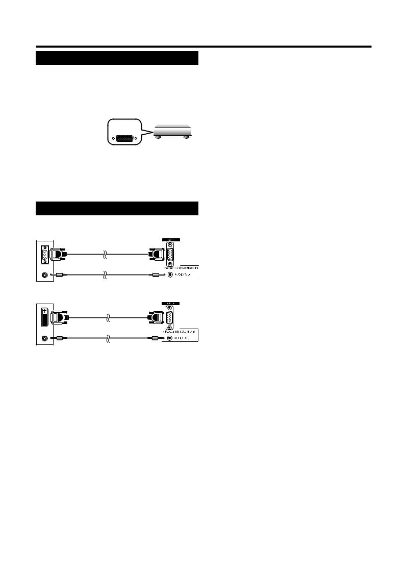
Connecting a PC
Use the EXT 4 terminals to connect a PC.
PC EXT 4
RGB cable*
ø 3.5 mm stereo minijack cable*
PC |
EXT 4 |
RGB/DVI conversion cable*
ø 3.5 mm stereo minijack cable*
NOTE
•The cables marked with * are commercially available items.
•The PC input terminals are DDC1/2B-compatible.
•Refer to page 41 for a list of PC signals compatible with the TV.
•Macintosh adaptor may be required for use for some Macintosh computers.
•When connecting to a PC, the correct input signal type is automatically detected.
HDMI connection
The HDMI connections (High Defi nition Multimedia Interface) permit digital video and audio transmission via a connection cable from a player.
The digital picture and sound data are transmitted without data compression and therefore lose none of their quality. Analogue/digital conversion is no longer necessary in the connected devices, which also would result in quality losses.
HDMI/DVI conversion
Using a DVI/HDMI adapter cable, the digital video signals of a DVD can also be played via the compatible HDMI connection. The sound must be fed in additionally. (Page 10)
HDMI and DVI both use the same copy protection method HDCP.
NOTE
•Video noise may occur depending on the type of HDMI cable used. Make sure to use certifi ed HDMI cable.
•When playing the HDMI image, the best possible format for the picture will be detected and set automatically.
Supported video signal:
VGA, 625i (576i), 625p (576p), 525i (480i), 525p (480p), 1125i (1080i), 750p (720p), 1125p (1080p)
If a connected HDMI device is AQUOS LINK compatible, you can take advantage of versatile functions using the AQUOS LINK buttons on the remote control.
See pages 12 - 14 for details.
 11
11
Using external equipment
Controlling HDMI devices using AQUOS LINK
What is AQUOS LINK?
Using the HDMI CEC (Consumer Electronics Control) protocol, with AQUOS LINK you can interactively operate compatible system devices (AV amplifi er, DVD, Blu-ray Disc device) using a single remote control.
NOTE
• AQUOS LINK-compatible AQUOS BD Player, AQUOS Audio speaker system and AQUOS Recorder will be on sale after the release of this TV. (As of May 2007)
What you can do with AQUOS LINK
One Touch Play
While the TV is in standby mode, it automatically turns on and plays back the image from the HDMI source.
Single remote control operation
The AQUOS LINK automatically recognises the connected HDMI device and you can control the TV and the devices as if using a universal remote control.
Operating Title list of external device
You can call up the external player’s Top Menu or the external recorder’s Title list provided that the devices support AQUOS LINK.
Multiple control of HDMI devices
You can select which HDMI device to operate using the OPTION button.
NOTE
•Point the remote control toward the TV, not to connected HDMI device.
•Video noise may occur depending on the type of HDMI cable used. Make sure to use a certifi ed HDMI cable.
•Up to 3 HDMI recording devices, one AV amplifi er and two players can be connected using this system.
•These operations affect the HDMI device selected as the current input source. If the device does not operate, turn on the device and select the appropriate input source using b.
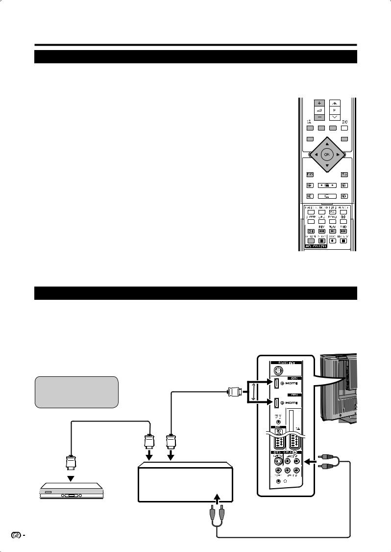
Connecting HDMI device to TV
First connect the AQUOS Audio speaker system or an AQUOS BD Player that supports HDMI CEC protocol.
NOTE
•Refer to the operation manual of the device to be connected for further details.
•After unplugging connection cables or changing the connection pattern, fi rst turn on the power of the TV with all relevant device’s power turned on. Change the external input source by pressing b, select the appropriate external source and verify the audiovisual output.
Connecting AQUOS
BD Player via AQUOS
Audio speaker system
Certifi ed HDMI cable (commercially available)
Certifi ed HDMI cable (commercially available)
TV
Output connection
|
|
|
|
|
|
|
|
|
|
|
|
|
|
|
|
|
|
|
|
|
|
|
|
|
|
|
|
|
|
|
|
|
|
|
|
|
|
|
|
|
|
|
|
|
|
|
|
|
|
|
|
|
|
|
|
|
|
|
|
|
|
|
|
|
|
|
|
|
|
|
|
|
|
|
|
|
|
|
|
|
|
|
|
|
|
|
|
|
|
|
|
|
|
|
|
|
|
|
|
|
|
|
|
|
|
|
|
|
|
|
|
|
|
|
|
|
|
|
|
|
|
|
|
|
|
|
|
|
|
|
|
|
|
|
|
|
|
|
|
|
|
|
|
|
|
|
|
|
|
|
|
|
|
|
|
|
|
|
|
|
|
|
|
|
|
|
|
|
|
|
|
|
|
|
|
|
|
|
|
AQUOS BD Player |
AQUOS Audio |
|
|
|
|
|
|
|
|
|
|
To Analogue Audio (L/R) input terminal |
|||||||||||||||||
|
|
||||||||||||||||||||||||||||
|
|
|
|
|
|
|
|
|
speaker system |
|
|
|
|
|
|
|
|
|
|
|
|
|
|
|
|
|
|
||
|
|
|
|
|
|
|
|
|
|
|
|
|
|
|
|
|
|
|
|
|
|
|
|
|
|
||||
|
|
|
|
|
|
|
|
|
|
|
|
|
|
|
|
|
|
|
|
|
|
|
|
||||||
|
|
|
|
|
|
|
|
|
|
|
|
|
|
|
|
|
|
|
|
|
|
||||||||
|
|
|
|
|
|
|
|
|
|
|
|
|
|
|
|
|
|
|
|
||||||||||
|
|
|
|
|
|
|
|
|
|
|
|
|
|
|
|
|
|
||||||||||||
|
|
|
|
|
|
|
|
|
|
|
|
|
|
|
|
|
|
||||||||||||
AUDIO cable
(commercially available)
12

Using external equipment
Connecting an AQUOS BD Player only
TV
Certifi ed HDMI cable |
AQUOS BD Player |
(commercially available) |
AQUOS LINK Auto Power On
If this is activated, the One Touch Play function is enabled.
While the TV is in standby mode, it automatically turns on and plays back the image from the HDMI source.
1Press MENU and the TV menu screen displays.
2Press c/d to select “Setup”, and then press
OK.
TV menu
Setup |
Geometry |
|
|
AQUOS LINK Auto Power On off
Channels
Child lock
Auto format on
Language
Blue illumination
Factory settings
Miscellaneous
3Press a/b to select “AQUOS LINK Auto Power On”.
4Press c/d to select “on”, and then press OK.
NOTE
• The factory default for this item is “off”.
Operating an AQUOS LINK device
AQUOS LINK allows you to operate the HDMIconnected device with one remote control.
1Open the remote control’s flip cover.
2Press PLAY Ito start playback of a title.
•See page 14, section “Playback of titles using AQUOS LINK” if you want to start playback using the list of the titles of the AQUOS BD Player.
3Press FWD Jto fast forward. Press REV Gto reverse. Press STOP Hto stop.
Press Bto turn the HDMI-connected device on/off.
Listening with the AQUOS Audio speaker system
You can opt to listen to the TV sound only from the AQUOS Audio speaker system and manually change its sound mode.
1Open the remote control’s flip cover.
2Press OPTION.
AQUOS LINK
AQUOS Recorder EPG
Top Menu/Title List
Media Change
By AQUOS Audio SP yes
Sound Mode Change
Model Select
3Press a/b to select “By AQUOS Audio SP”.
4Press c/d to select “yes”.
•Select “no” to listen to the TV sound.
•The sound from the TV speaker and headphone terminal is muted and only the sound from the AQUOS Audio speaker system is audible.
•You can control the AQUOS Audio Speaker system’s volume (ik/l) and mute functions (e).
Manually changing AQUOS Audio speaker system’s sound mode
1Open the remote control’s flip cover.
2Press OPTION.
• The AQUOS LINK menu displays.
3Press a/b to select “Sound mode change”.
4The sound mode changes every time you press
OK.
•Refer to the operation manual of the AQUOS Audio speaker system for details.
 13
13
Loading...