


 Loading...
1st Addition
SERVICE MANUAL
No.S13M1460LE631MX-WH
LCD COLOUR TELEVISION
MODEL :LC-60LE631M-WH
LC-60LE631X-WH
In the interests of user-safety (Required by safety regulations in some countries) the set should be restored to its original condition and only parts identical to those specified should be used.
CONTENTS
CHAPTER 1.OUTLINE AND DIFFERENCES FROM BASE MODEL
OUTLINE/
DIFFERENCES FROM BASE MODEL ...1
SAFETY PRECAUTION |
|
IMPORTANT SERVICE SAFETY |
|
PRECAUTION....................................... |
1-2 |
PRECAUTION FOR USING LEED-FREE |
|
SOLDER............................................... |
1-3 |
[2] MAJOR SERVICE PARTS |
|
MAJOR SERVICE PARTS...................... |
1-4 |
CHAPTER 2. SPECIFICATIONS |
|
[1] SPECIFICATION................................. |
2-1 |
CHAPTER 3.OPERATION MANUAL |
|
[1] OPERATION MANUAL........................ |
3-1 |
CHAPTER 4.DIMENSIONS |
4-1 |
[1] DIMENSIONS ............................. |
|
CHAPTER 5. REMOVING OF MAJOR PARTS
[1] REMOVING OF MAJOR PARTS........... |
5-1 |
|
CHAPTER 6. TROUBLESHOOTING TABLE |
6-1 |
|
[1] |
TROUBLESHOOTING TABLE ......................... |
|
CHAPTER 7. OVERALL WIRING/BLOCK DIAGRAM |
||
[1] OVERALL WIRING DIAGRAM ............................ |
7-1 |
|
[2] SYSTEM BLOCK DIAGRAM............................ |
7-2 |
|
CHAPTER 8. PRINTED WIRING BOARD ASSEMBLIES |
||
[1] |
Main Unit ................................................... |
8-1 |
[2] |
T-CON Unit .............................................. |
8-9 |
[3] |
RC/LED Unit ......................................... .. |
8-13 |
[4] |
KEY Unit ................................................... |
8-15 |
CHAPTER 9. SCHEMATIC DIAGRAM |
|
|
[1] |
DESCRIPTION OF SCHEMATIC |
|
|
DIAGRAM.................................................. |
9-1 |
[2]MAIN Unit.. ...............................................9-2
[3] |
T-CON Unit. ............................................. |
9-5 |
[4] |
RC/LED Unit ............................................ |
9-15 |
[5] |
KEY Unit ................................................... |
9-17 |
Parts Guide
Parts marked with "  " are important for maintaining the safety of the set. Be sure to replace these parts with specified ones for maintaining the safety and performance of the set.
This document has been published to be used for after sales service only.
The contents are subject to change without notice.

LC-60LE631M/X-WH
CHAPTER 1. OUTLINE AND DIFFER-
ENCES FROM BASE MODEL
[1] OUTLINE / DIFFERENCES FROM BASE MODEL
This model is based on the LC-60LE630M/X and partially modified.
For the contents not covered in this Service Manual, accordingly, please refer to the LC-60LE630M/X Service Manual
DIFFERENCES FROM BASE MODEL

 LIST OF CHANGED PARTS
KEYMF904FM10 (60LE631M-WH) |
Part code changed |
KEYMF904FM12 (60LE631X-WH) |
Part code changed |
Ref. No. |
Description |
LC-60LE630M/X |
LC-60LE631M/X-WH |
Note |
PRINTED WIRING BOARD ASSEMBLIES |
|
|
||
N |
MAIN Unit |
DKEYMF904FMG1 |
DKEYMF904FM10 |
Part code changed |
|
|
|
|
|
N |
MAIN Unit |
DKEYMF904FMG2 |
DKEYMF904FM12 |
Part code changed |
N |
R/C LED Unit |
RUNTKF799FMF7 |
DUNTKG016FMF8 |
Changed |
N |
KEY Unit |
DUNTKF800FMF7 |
DUNTKF800FMF8 |
Changed |
|
|
|
|
|
N |
POWER Unit |
RUNTKA847WJN1 |
RUNTKB057WJQZ |
Changed |
|
|
|
|
|
N |
T-CON |
DUNTKF908FM06 |
DUNTKF908FM11 |
Changed |
|
|
|
|
|
LCD PANEL |
|
|
|
|
N |
LCD Panel Module Unit |
R1LK600D3GW8BW |
R1LK600D3GV0DF |
Changed |
CABINET PARTS, SUPPLIED ACCESSORIES, PACKING PARTS (NOT REPLACEMENT ITEM), SERVICE JIGS (USE FOR SERVICING) Please refer to a Parts list.
1 – 1
SAFETY PRECAUTIONSAFETY PRECAUTIONSAFETY PRECAUTIONSAFETY PRECAUTIONSAFETY PRECAUTIONSAFETY PRECAUTIONSAFETY PRECAUTIONSAFETY PRECAUTIONSAFETY PRECAUTIONSAFETY PRECAUTIONSAFETY PRECAUTIONSAFETY
LC32LE240M
LC-60LE631M/X-WH
5GTXKEG /CPWCN
IMPORTANT SERVICE SAFETY PRECAUTION

 Service work should be performed only by qualified service technicians who are thoroughly familiar with all safety checks and the servicing guidelines which follow:
WARNING
1.For continued safety, no modification of any circuit should be attempted.
2.Disconnect AC power before servicing.
BEFORE RETURNING THE RECEIVER (Fire &
Shock Hazard)
Before returning the receiver to the user, perform the following safety checks:
3.Inspect all lead dress to make certain that leads are not pinched, and check that hardware is not lodged between the chassis and other metal parts in the receiver.
4.Inspect all protective devices such as non-metallic control knobs, insulation materials, cabinet backs, adjustment and compartment covers or shields, isolation resistor-capacitor networks, mechanical insulators, etc.
All checks must be repeated with the AC cord plug connection reversed. (If necessary, a nonpolarized adaptor plug must be used only for the purpose of completing these checks.)
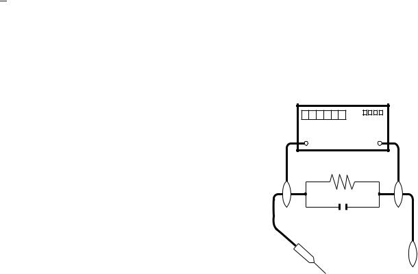
Any reading of 0.74 Vrms (this corresponds to 0.5 mA rms AC.) or more is excessive and indicates a potential shock hazard which must be corrected before returning the monitor to the owner.
DVM
AC SCALE
1.5k ohm
10W
5.To be sure that no shock hazard exists, check for leakage current in the following manner.
•Plug the AC cord directly into a 110-240 volt AC outlet.
•Using two clip leads, connect a 1.5k ohm, 10 watt resistor paralleled by a 0.15 F capacitor in series with all exposed metal cabinet parts and a known earth ground, such as electrical conduit or electrical ground connected to an earth ground.
•Use an AC voltmeter having with 5000 ohm per volt, or higher, sensitivity or measure the AC voltage drop across the resistor.
•Connect the resistor connection to all exposed metal parts having a return to the chassis (antenna, metal cabinet, screw heads, knobs and control shafts, escutcheon, etc.) and measure the AC voltage drop across the resistor.
0.15 µF
TEST PROBE
TO EXPOSED |
CONNECT TO |
METAL PARTS |
KNOWN EARTH |
|
GROUND |
///////////////////////////////////////////////////////////////////////////////////////////////////////////////////////////////////////////////////////////////////////////////////////////////////////////////////////////////////////////
SAFETY NOTICE
Many electrical and mechanical parts in LCD colour television have special safety-related characteristics.
These characteristics are often not evident from visual inspection, nor can protection afforded by them be necessarily increased by using replacement components rated for higher voltage, wattage, etc.
Replacement parts which have these special safety characteristics are identified in this manual; electrical components having such features
are identified by " " and shaded areas in the Replacement Parts List and Schematic Diagrams.
For continued protection, replacement parts must be identical to those used in the original circuit.
The use of a substitute replacement parts which do not have the same safety characteristics as the factory recommended replacement parts shown in this service manual, may create shock, fire or other hazards.
///////////////////////////////////////////////////////////////////////////////////////////////////////////////////////////////////////////////////////////////////////////////////////////////////////////////////////////////////////////
PRECAUTIONSAFETY PRECAUTIONSAFETY PRECAUTIONSAFETY PRECAUTIONSAFETY PRECAUTION
1 – 2

LC-60LE631M/X-WH
PRECAUTIONS FOR USING LEAD-FREE SOLDER
Employing lead-free solder
•“PWBs” of this model employs lead-free solder. The LF symbol indicates lead-free solder, and is attached on the PWBs and service manuals. The alphabetical character following LF shows the type of lead-free solder.
Example:
|
|
|
|
|
|
|
|
|
|
|
|
|
|
|
|
|
|
|
|
|
|
|
|
Indicates lead-free solder of tin, silver and copper. |
Indicates lead-free solder of tin, silver and copper. |
||||||||||
Using lead-free wire solder
•When fixing the PWB soldered with the lead-free solder, apply lead-free wire solder. Repairing with conventional lead wire solder may cause damage or accident due to cracks.
As the melting point of lead-free solder (Sn-Ag-Cu) is higher than the lead wire solder by 40 C, we recommend you to use a dedicated soldering bit, if you are not familiar with how to obtain lead-free wire solder or soldering bit, contact our service station or service branch in your area.
Soldering
•As the melting point of lead-free solder (Sn-Ag-Cu) is about 220 C which is higher than the conventional lead solder by 40 C, and as it has poor solder wettability, you may be apt to keep the soldering bit in contact with the PWB for extended period of time. However, Since the land may be peeled off or the maximum heat-resistance temperature of parts may be exceeded, remove the bit from the PWB as soon as you confirm the steady soldering condition.
Lead-free solder contains more tin, and the end of the soldering bit may be easily corroded. Make sure to turn on and off the power of the bit as required.
If a different type of solder stays on the tip of the soldering bit, it is alloyed with lead-free solder. Clean the bit after every use of it. When the tip of the soldering bit is blackened during use, file it with steel wool or fine sandpaper.
•Be careful when replacing parts with polarity indication on the PWB silk.
Lead-free wire solder for servicing
PARTS CODE |
PRICE |
PART |
DESCRIPTION |
|
RANK |
DELIVERY |
|||
|
|
|||
ZHNDAi123250E |
BL |
J |
0.3mm 250g (1roll) |
|
ZHNDAi126500E |
BK |
J |
0.6mm 500g (1roll) |
|
ZHNDAi12801KE |
BM |
J |
1.0mm 1kg (1roll) |
1 – 3

LC-60LE631M/X-WH
[2] MAJOR SERVICE PARTS
MAJOR SERVICE PARTS
MAJOR SERVICE PARTS

 PWB UNIT
Ref No. |
Part No. |
Description |
N |
DKEYMF904FM10 |
MAIN Unit (LC-60LE631M-WH) |
N |
DKEYMF904FM12 |
MAIN Unit (LC-60LE631X-WH) |
N |
DUNTKG016FMF8 |
R/C LED Unit |
N |
DUNTKF800FMF8 |
KEY Unit |
N |
RUNTKB057WJQZ |
POWER Unit |
N |
DUNTKF908FM11 |
T-CON Unit |
 OTHER UNIT
Ref No. |
Part No. |
Description |
N |
R1LK600D3GV0DF |
60" LCD Panel Module Unit |
 SERVICE JIGS
Ref No. |
Part No. |
|
Description |
Q’ty |
N |
QCNW-C222WJQZ |
Connecting Cord,T-Con - LCD Panel |
|
2 |
N |
QCNW-F676WJQZ |
Connecting Cord, Main-T-Con (LW) |
|
1 |
N |
QCNW-G405WJQZ |
Connecting Cord, Main-T-Con (PL) |
|
1 |
N |
QCNW-N125WJPZ |
Connecting Cord, Main-Power (PD) |
|
1 |
1 – 4

LC-60LE631M/X-WH
CHAPTER 2. SPECIFICATIONS
[1] SPECIFICATIONS
Item |
|
|
|
|
Model |
LC-60LE631M-WH / LC-60LE631X-WH |
|
|
|
|
|
|
|
|
|
LCD panel |
|
|
|
|
60" (1525 mm) Active Matrix type a - Si TFT |
||
|
|
|
|
|
|
|
|
Resolution |
|
|
|
|
2,073,600 pixels (1920 x 1080) |
||
|
|
|
|
|
|
|
|
Video Colour System |
|
PAL/SECAM/NTSC 3.58/NTSC 4.43/PAL 60 |
|||||
|
|
|
|
|
|
||
TV |
TV-Standard ( 60LE631M-WH ) |
PAL: B/G, D/K, I SECAM: B/G, D/K, K/K1 NTSC: M |
|||||
Function |
|
|
|
|
|
|
|
TV-Standard |
|
Analogue |
PAL: B/G, D/K, I SECAM: B/G, D/K, K/K1 |
||||
|
(60LE631X-WH) |
|
Digital |
DVB-T |
|
||
|
Receiving |
|
VHF/UHF |
44.25 — 863.25 MHz |
|||
|
Channel |
|
|
|
|
||
|
|
CATV |
S1 — S41ch (including Hyperband) |
||||
|
|
|
|
|
|||
|
|
|
|
|
|
||
|
TV-Tuning System |
Auto Preset 99 ch |
|||||
|
|
|
|
|
|||
|
STEREO/BILINGUAL |
NICAM: B/G, I, D/K A2 stereo: B/G |
|||||
|
|
|
|
|
|
|
|
Viewing angles |
|
H : 176º V : 176º |
|||||
|
|
|
|
|
|
||
Audio amplifier |
|
10 W x 2 |
|
||||
|
|
|
|
|
|
|
|
Speakers |
|
|
|
|
3.2 x 15 cm |
2pcs |
|
|
|
|
|
|
|||
Terminals |
Antenna input |
UHF/VHF 75 |
DIN type |
||||
|
|
|
|
|
|
||
|
|
HDMI 1 |
|
HDMI (HDMI input) (480I, 576I, 480P, 576P, 720P/50Hz, 720P/60Hz, 1080I/50Hz, |
|||
|
|
|
|
|
|
1080I/60Hz, 1080P/50Hz, 1080P/60Hz, 1080P/24Hz), AUDIO in (common use with |
|
|
|
|
|
|
|
PC) (Ø 3.5 mm jack) |
|
|
|
|
|
|
|
||
|
|
HDMI 2 |
|
HDMI (HDMI input) (480I, 576I, 480P, 576P, 720P/50Hz, 720P/60Hz, 1080I/50Hz, |
|||
|
|
HDMI 3 |
|
1080I/60Hz, 1080P/50Hz, 1080P/60Hz, 1080P/24Hz) |
|||
|
|
|
|
|
|
||
|
|
INPUT 4 |
|
VIDEO in, AUDIO in |
|||
|
|
|
|
|
|
||
|
|
INPUT 5 |
|
VIDEO in, AUDIO in |
|||
|
|
|
|
|
|
||
|
|
INPUT 6 |
|
AUDIO in, COMPONENT in (480I, 576I, 480P, 576P, 720P/50Hz, 720P/60Hz, |
|||
|
|
|
|
|
|
1080I/50Hz, 1080I/60Hz) |
|
|
|
|
|
|
|
||
|
|
AUDIO OUT |
Audio out |
|
|||
|
|
|
|
|
|||
|
|
AUDIO IN (R/L) |
Ø 3.5 mm jack* |
||||
|
|
|
|
|
|
||
|
|
PC |
|
15 pin mini D-sub, AUDIO in (common use with HDMI 1) (Ø 3.5 mm jack) |
|||
|
|
|
|
|
|
|
|
|
|
USB |
|
USB |
|
||
|
|
|
|
|
|
||
|
|
RS-232C |
|
9 pin D-sub male connector |
|||
|
|
|
|
|
|||
|
|
DIGITAL AUDIO OUTPUT |
Optical Digital Audio Output |
||||
|
|
|
|
|
|||
|
|
Headphones |
Ø 3.5 mm jack |
||||
|
|
|
|
||||
OSD language (60LE631M-WH) |
English/Simplified Chinese/Arabic/French/Portuguese/Russian/Persian/Thai/ |
||||||
|
|
|
|
|
|
Vietnamese/Indonesian |
|
OSD language (60LE631X-WH) |
English |
|
|||||
Power Requirement |
|
AC 110 — 240 V, 50/60 Hz |
|||||
|
|
|
|
||||
Power Consumption |
|
188 W (0.5 W Standby) |
|||||
|
|
|
|
|
|||
Dimensions |
|
without stand (mm) |
1384 (W) x 839 (H) x 73 (D) |
||||
|
|
|
|||||
|
with stand (mm) |
1384 (W) x 874 (H) x 341.5 (D) |
|||||
|
|
|
|||||
Weight without stand (with stand) |
25.5 kg (28.5 kg) |
||||||
|
|
|
|
||||
Operating Temperature |
|
0°C — 40°C |
|
||||
* The HDMI1 and PC terminals can both use the same audio input terminal.
 As a part of policy of continuous improvement, SHARP reserves the right to make design and specification changes for product improvement without prior notice. The performance specification figures indicated are nominal values of production units. There may be some deviations from these values in individual units.
2 – 1
CHAPTER 3. OPERATION MANUAL
[1] OPERATION MANUAL
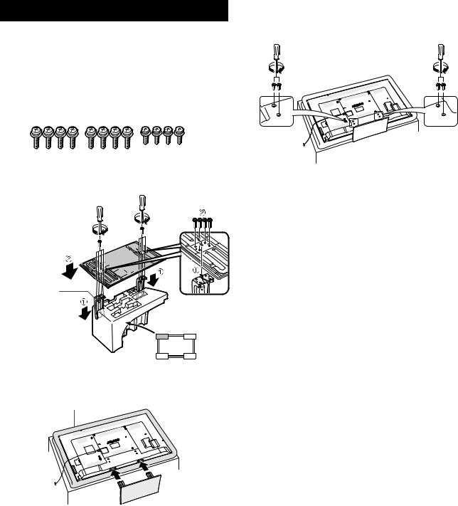
Attaching the stand unit
Before performing work, spread cushioning over the surface on which you will be laying the TV. This will prevent it from being damaged.
CAUTION
Attach the stand in the correct direction.
Be sure to follow the instructions. Incorrect installation of the stand may result in the TV falling over.
1 C onfirm that there are s crews with the s tand unit.
(Eight long screws and four short screws)
2 Attach the s upporting pos t for the s tand unit onto the bas e us ing the long s crews with a s crewdriver as s hown.
Supporting
post
Front
3 Ins ert the s tand into the openings on the bottom of the TV (hold the s tand s o it will not drop from the edge of the bas e area).
Soft cushion
LC-60LE631M/X-WH
4 Attaching the s tand cover.
1Insert the stand cover.
2Insert and tighten four short screws into the holes of the stand cover.
NOTE
To detach the stand unit, perform the steps in reverse order.
A screwdriver is not supplied with this product.
3 – 1

LC-60LE631M/X-WH
CHAPTER 4. DIMENSIONS
[1] DIMENSIONS
Dimensional drawings
Unit: mm
1384
1333*1*1
341.5
400
10 ο
78 1
106 |
219 |
AN-52AG4
6 38
8 43
I Active area
NOTE
• Dimensions do not include protrusions such as screws and some parts.
4 – 1
CHAPTER 5. REMOVING OF MAJOR
PARTS
JOR
PAR
TRE
MO
VIN
[1] REMOVING OF MAJOR PARTS G
OF
MAJ
OR
PAR
TRE
MO
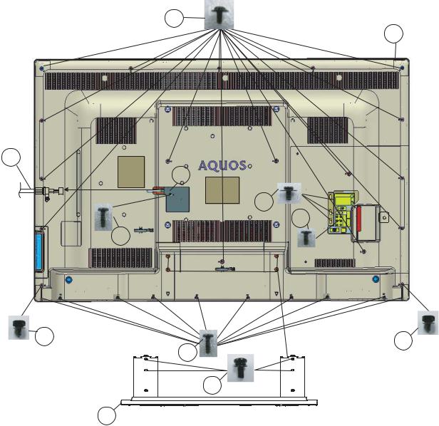
1. Removing of the Stand Unit and Rear CabinetVIN
G
OF
1. Remove the 4 lock screws [1] and detach the Stand Unit [2]MAJ.
OR
PAR
TRE
2. Remove the 1 lock screw [3] and detach the AC Cord CoverMO [4].
VIN
G
3. Disconnect AC Cord [5]. OF
MAJ
OR
4. Remove the 16 lock screws [6], 1 lock screw [7], 3 lock screwsPAR [8], 2 lock screw [9],
TRE
MO
VIN
5. Remove the 10 lock screws [10], and detach the Rear CabinetG A ss’y [11].
OF
MAJ
OR
PAR
TRE
MO
VIN
G
OF
6
OF
MAJ
OR
PAR
TRE
MO
VIN
G
5
4
8
7
3
9
10
1
2
LC-60LE631M/X-WH
11
9
5 – 1

LC-60LE631M/X-WH
2. Removing of Connectors
1.Disconnect the following connectors from the MAIN Unit. (PD, LW, PL, RA)
2.Disconnect the following connectors from the POWER Unit. ( PD )
3.Disconnect the following connectors from the LCD CONTROL Unit. (LW, PL, FFC)
4.Disconnect the following connectors from the KEY Unit. (KM)
5.Disconnect the following connectors from the R/C, LED Unit. (RA)
5 – 2
LC-60LE631M/X-WH
3. R emoving of S peaker (L/R)
1. R emove the 4 Hooks and detach the 2 Bottom Cover (8) .
2. Detach the S peake r (L) (1) , S pea ker (R) (2) .
5 – 3

LC-60LE631M/X-WH
4. Removing of the PWB Units
1.Detach the Key Cover [1], remove the 2 lock screws [2], detach the Key Button [3] and detach the KEY Unit [4].
2.Detach the R/C LED Unit [5].
3.Detach the Side Cover [6].
4.Remove the 2 lock hexagon screws [7] and 2 lock hexagon screws [8].
5. |
Remove the 10 lock screws [9] and detach the MAIN Unit [10] and POWER Unit [11]. |
6. |
Remove the 6 lock screws [12] and detach the LCD CONTROL Unit [13]. |
10 9 
 7
7
Side Cover
6
8 |
MAIN Unit 10 |
|
POWER Unit 11
Key Button |
|
3 |
2 |
|
KEY Unit
4
KEY Cover
1
R/C LED Unit 5
12
LCD CONTROL Unit 13
5 – 4

LC-60LE631M/X-WH
5. Removing of the LCD Panel Module Unit
1. Detach the 21 Hooks [1] and detach the LCD Panel Module Unit [2].
1
5 – 5

LC-60LE631M/X-WH
[2]PRECAUTIONSFORASSEMBLY
[Precautions when fixing the Rear Cabinet]
When fixing the Rear Cabinet, be careful not to catch the backlight LED harness, speaker harness and other harnesses in it.
•The hooks on the external wall of the Rear Cabinet are fitted in the Front Cabinet Ass’y. After putting the Rear Cabinet in place, fit the hooks securely; then tighten the screws.
(Work method of Rear Cabinet fixation)
Rear Cabinet (Mat parts)
Front Cabinet Ass'y (Luster parts)
There is a gap without the fingernail fitting in completely only when covering with Rear Cabinet.
It becomes the factor of a gap increase of Front Cabinet Ass'y/Rear Cabinet and the Rear Cabinet misregistration.
Please tighten the screw after Rear Cabinet is firmly pushed, and the fingernail is confirmed.
(Front Cabinet Ass’y/Rear Cabinet fingernail fixation place)
5 – 6
LC-60LE631M/X-WH
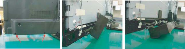
[3] THE way of detaching Rear Cabinet
[Precaution when removing the rear cabinet]
If the rear cabinet is removed with the set upright, the speakers may fall; it results in connector disconnection. Therefore, never remove the rear cabinet with the set upright.
Be sure to remove the rear cabinet with the screen side down.
|
|
|
|
Speaker fall down. |
Screws for fixing Speaker |
|
Speaker incline. |
|
|
and Rear Cabinet |
|
|
|
|
|
|
|
|
|
[Precaution when mounting the rear cabinet]
Put the speakers in place with the screen side down, and attach the rear cabinet.
Since the speakers are fixed by the rear cabinet, they cannot be fixed without the rear cabinet.
5 – 7

LC-60LE631M/X-WH
CHAPTER 6. TROUBLESHOOTING
TABLE
[1] TROUBLESHOOTING TABLE
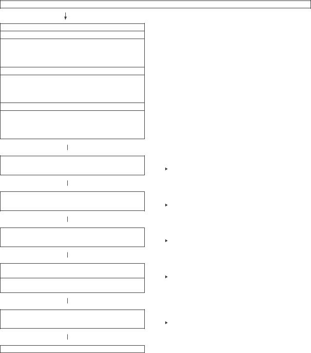
No power (front LED failure to light up) or no startup (front LED failure to turn from red to green)
Is the AC cord plug tightly connected to the set?
YES
Is the output voltage at pin (9) of P9601 (BU+5V line) as specified?
Is the output voltage at pin (17), (18), (19) and (20) of P9601 (13V line) as specified?
NO |
Reconnect the AC cord tightly and turn on the power again. |
|
|
|
|
|
|
|
|
|
|
NO |
Replace the power unit. |
|
|
|
|
|
|
|
|
|
YES |
|
|
|
|
Are the wire harnesses and other cables properly connected in |
|
NO |
Reconnect the wire harnesses and other cables properly in the |
|||
the set? |
|
|
|
set. |
||
|
|
|
|
|
|
|
|
|
YES |
|
|
|
|
|
|
|
|
|
|
|
|
|
|
|
|
|
|
Is there the AC_DET and PNL_ON signal input at pins (11) and |
|
NO |
Check the AC_DET signal line PNL_ON signal line. |
|||
(10) of P9601? |
|
|
|
|
||
|
|
|
|
|
|
|
|
|
YES |
|
|
|
|
|
|
|
|
|
|
|
|
|
|
|
|
|
|
Are the DC/DC converter outputs and the output voltages along |
|
NO |
Check the DC/DC converters and the control lines. Replace |
|||
the control lines as specified? |
|
|
|
defective parts as required. |
||
|
|
|
|
|
|
|
1) |
B1.26V (IC9604) |
|
|
|
|
|
2) |
B5.6V (IC9602) |
|
|
|
|
|
3) |
BU3.3V (IC9601) |
|
|
|
|
|
4) |
D3.3V (IC9606) |
|
|
|
|
|
5) |
B5V (IC9611) |
|
|
|
|
|
6) |
B1.8V (IC9610) |
|
|
|
|
|
7) |
AU3.3V (IC9603) |
|
|
|
|
|
8) |
AU1.8V (IC9607) |
|
|
|
|
|
With [RF] signal input |
No video onscreen (1) |
||||||
|
|
|
|
|
|
|
|
|
|
|
|
|
|
|
|
|
|
|
|
|
|
|
|
No video in the UHF/VHF reception |
|
|
|
|
|
||
|
|
|
|
|
|
|
|
|
|
|
|
|
|
|
|
|
|
|
|
|
|
|
|
Is there IF output from the tuner pin(12) of TU1103 as specified? |
NO |
Check TU1103 and its peripheral circuits. |
|||||
Is there VIDEO output from the tuner pin(16) of TU1103 as speci- |
|
|
|
|
|||
fied? |
|
|
|
|
|
||
|
|
YES |
|
|
|
|
|
|
|
|
|
|
|
|
|
|
|
|
|
|
|
|
|
Is there VIDEO input at pin (M3) of IC3303? |
|
NO |
Check the circuit between TU1103 & IC3303. |
||||
|
|
|
|
|
|
|
|
|
|
|
|
|
|
|
|
|
|
YES |
|
|
|
|
|
|
|
|
|
|
|
|
|
|
|
|
|
|
|
|
|
Are there the signal outputs at pin AC (21), (22), (23), (24), AD |
NO |
Check IC3303 and its peripheral circuit. |
|||||
(21), (22), (23), (24) and AE (21), (22), (23), (24) of IC3303? |
|
|
|
|
|
||
|
|
|
|
|
|
|
|
|
|
YES |
|
|
|
|
|
|
|
|
|
|
|
|
|
|
|
|
|
|
|
|
|
Check LVDS cable, LCD controller (incl. panel) and their periph- |
|
|
|
|
|||
eral circuits. |
|
|
|
|
|
||
6 – 1

LC-60LE631M/X-WH
No audio heard (1)
No sound in the UHF/VHF reception. |
|
|
|
|
|
||
|
|
|
|
|
|
|
|
|
|
|
|
|
|
|
|
|
|
|
|
|
|
|
|
Is the IF output from the tuner pin (13) of TU1103 as specified? |
|
NO |
Check TU1103 and its peripheral circuits. |
||||
|
|
|
|
|
|
|
|
|
|
|
|
|
|
|
|
|
|
YES |
|
|
|
|
|
|
|
|
|
|
|
|
|
|
|
|
|
|
|
|
|
Is there the signal input at pins (W3) of IC3303? |
|
NO |
Check IC3303 and its peripheral circuits. |
||||
|
|
|
|
|
|
|
|
|
|
|
|
|
|
|
|
|
|
YES |
|
|
|
|
|
|
|
|
|
|
|
|
|
|
|
|
|
|
|
|
|
Is there I2S_LRCLK signal input at pin(9) of IC2707? |
|
NO |
Check connection between IC3303 and IC2707 and its |
||||
|
|
|
|
|
|
|
peripheral circuits. |
|
|
|
|
|
|
|
|
|
|
YES |
|
|
|
|
|
|
|
|
|
|
|
|
|
|
|
|
|
|
|
|
|
Is there AMP_LRCLK signal input at pin(8) of IC2704? |
|
NO |
Check connection between IC2707 and IC2704 and its |
||||
|
|
|
|
|
|
|
peripheral circuits. |
|
|
|
|
|
|
|
|
|
|
YES |
|
|
|
|
|
|
|
|
|
|
|
|
|
|
|
|
|
|
|
|
|
Is the L-ch audio signal output at pin(28) and (30) of IC2704 normal? |
|
NO |
Check IC2704 and its peripheral circuits. |
||||
Is the R-ch audio signal output at pin(12) and (14) of IC2704 normal? |
|
|
|
|
|
||
|
|
|
|
|
|
|
|
|
|
YES |
|
|
|
|
|
|
|
|
|
|
|
|
|
|
|
|
|
|
|
|
|
Are the audio signal L-ch and R-ch output at (4)/(5) and (1)/(3) of |
|
NO |
Check circuit between IC2704 & P2702. |
||||
P2702 normal? |
|
|
|
|
|
||
|
|
|
|
|
|
|
|
|
|
YES |
|
|
|
|
|
|
|
|
|
|
|
|
|
|
|
|
|
|
|
|
|
Check speakers and their peripheral circuits. |
|
|
|
|
|
||
6 – 2
LC-60LE631M/X-WH
No audio heard (2)
No external audio heard
<INPUT 4>
Is there the L-ch audio signal input from pin (15) of input terminal J504 to pin (AE2) of IC3303?
Is there the R-ch audio signal input from pin (8) of input terminal J504 to pin (AE3) of IC3303?
<INPUT 5>
Is there the L-ch audio signal input from pin (16) of input terminal J504 to pin (AB1) of IC3303?
Is there the R-ch audio signal input from pin (10) of input terminal J504 to pin (AA1) of IC3303?
<INPUT 6>
Is there the L-ch audio signal input from pin (2) of input terminal J503 to pin (Y1) of IC3303?
Is there the R-ch audio signal input from pin (4) of input terminal J503 to pin (AA3) of IC3303?
 YES
YES
Is there the I2S signal output at pin A8, C7, B7 and D8 of IC3303?
 YES
YES
Is there I2S_LRCLK signal input at pin(9) of IC2707?
 YES
YES
Is there AMP_LRCLK signal input at pin(8) of IC2704?
 YES
YES
Is the L-ch audio signal output at pin(28) and (30) of IC2704 normal?
Is the R-ch audio signal output at pin(12) and (14) of IC2704 normal?
 YES
YES
Are the audio signal L-ch and R-ch output at (4)/(5) and (1)/(3) of P2702 normal?
 YES
YES
Check speakers and their peripheral circuits.
|
NO |
Check IC3303 and its peripheral circuits. |
||
|
|
|
|
|
|
|
|
|
|
|
|
|
|
|
|
|
|
|
|
|
|
|
|
|
|
NO |
Check connection between IC3303 and IC2707 and its periph- |
||
|
|
|
|
eral circuits. |
|
|
|
|
|
|
|
|
|
|
|
|
|
|
|
|
|
|
|
|
|
NO |
Check connection between IC2707 and IC2704 and its periph- |
||
|
|
|
|
eral circuits. |
|
|
|
|
|
|
|
|
|
|
|
|
|
|
|
|
|
|
|
|
|
NO |
Check IC2704 and its peripheral circuits. |
||
|
|
|
|
|
|
|
|
|
|
|
|
|
|
|
|
|
|
|
|
|
|
|
|
|
|
NO |
Check circuit between IC2704 & P2702. |
||
|
|
|
|
|
|
|
|
|
|
|
|
|
|
|
|
|
|
|
|
6 – 3

LC-60LE631M/X-WH
No audio heard (3)
No HDMI sound heard. HDMI1 (*INPUT 1 is digital audio.)
Does the HDMI image appear onscreen?
YES
No audio output from HDMI1.
YES
Are waveforms input in to the pin F1, F2, G1, G2, G3, H1, H2 and H3 of IC3303 normally and I2S output normally?
Are waveforms input in to the pin A8, C7, B7 and D8 of IC3303 normally and I2S output normally?
 YES
YES
Is there I2S_LRCLK signal input at pin(9) of IC2707?
 YES
YES
Is there AMP_LRCLK signal input at pin(8) of IC2704?
 YES
YES
Is the L-ch audio signal output at pin (28) and (30) of IC2704 normal?
Is the R-ch audio signal output at pin (12) and (14) of IC2704 normal?
 YES
YES
Are the audio signal L-ch and R-ch output at (4)/(5) and (1)/(3) of P2702 normal?
 YES
YES
Check speakers and their peripheral circuits.
|
NO |
Refer to “HDMI1 in No external input video onscreen (HDMI)”. |
|||
|
|
|
|
|
|
|
|
|
|
|
|
|
|
|
|
|
|
|
|
|
|
|
|
|
NO |
Check the EDID. |
||
|
|
|
|
|
|
|
|
|
|
|
|
|
|
|
|
|
|
|
|
|
NO |
Check peripheral circuits of IC3303. |
|||
|
|
|
|
|
|
|
|
|
|
|
|
|
|
|
|
|
|
|
|
|
|
|
|
|
NO |
Check connection between IC3303 and IC2707 and its periph- |
|||
|
|
|
|
|
eral circuits. |
|
|
|
|
|
|
|
|
|
|
|
|
|
|
|
|
|
|
|
NO |
Check connection between IC2707 and IC2704 and its periph- |
|||
|
|
|
|
|
eral circuits. |
|
|
|
|
|
|
|
|
|
|
|
|
|
|
|
|
|
|
|
NO |
Check IC2704 and its peripheral circuits. |
||
|
|
|
|
|
|
|
|
|
|
|
|
|
|
|
|
|
|
|
|
|
NO |
|
Check circuit between IC2704 & P2702. |
||
|
|
|
|
|
|
|
|
|
|
|
|
|
|
|
|
|
|
|
|
|
|
|
|
6 – 4

LC-60LE631M/X-WH
No audio heard (4)
No sound from the HDMI sound input terminal. (HDMI1 analog audio)
 YES
YES
Is there the L-ch audio signal input from pin (2) of external input terminal J506 (HDMI AUDIO IN) to pin (AC2) of IC3303?
Is there the R-ch audio signal input from pin (3) of external input terminal J506 (HDMI AUDIO IN) to pin (AB2) of IC3303?
|
|
|
YES |
|
|
|
|
|
|
|
|
|
|
|
|
|
|
|
|
|
|
|
|
|
|
|
|
|
|
|
|
|
|
|
|
|
|
|
|
|
|
|
|
Are I2S signal output at pin A8, C7, B7 and D8 of IC3303 nor- |
|
|
NO |
Check peripheral circuits of IC3303. |
||||||
mally? |
|
|
|
|
|
|
|
|||
|
|
|
|
|
|
|
||||
|
|
|
|
|
|
|
|
|
|
|
|
|
|
|
|
|
|
|
|
|
|
|
|
|
YES |
|
|
|
|
|
|
|
|
|
|
|
|
|
|
|
|
|
|
|
|
|
|
|
|
|
|
|
|
|
|
|
|
|
|
|
|
|
|
|
|
|
|
|
|
|
|
|
|
|
|
|
Is there I2S_LRCLK signal input at pin(9) of IC2707? |
|
|
NO |
Check connection between IC3303 and IC2707 and its periph- |
||||||
|
|
|
|
|
|
|
|
|
|
eral circuits. |
|
|
|
|
|
|
|
|
|
|
|
|
|
|
|
|
|
|
|
|
|
|
|
|
|
|
|
|
|
|
|
|
|
|
|
|
YES |
|
|
|
|
|
|
|
|
|
|
|
|
|
|
|
|
|
|
|
|
|
|
|
|
|
|
|
|
|
|
|
|
|
|
|
|
|
|
|
|
|
|
|
|
|
|
|
|
|
|
|
Is there AMP_LRCLK signal input at pin(8) of IC2704? |
|
|
NO |
Check connection between IC2707 and IC2704 and its periph- |
||||||
|
|
|
|
|
|
|
|
|
|
eral circuits. |
|
|
|
|
|
|
|
|
|
|
|
|
|
|
|
|
|
|
|
|
|
|
|
|
|
|
|
|
|
|
|
|
|
|
|
|
YES |
|
|
|
|
|
|
|
|
|
|
|
|
|
|
|
|
|
|
|
|
|
|
|
|
|
|
|
|
|
|
|
|
|
|
|
|
|
|
|
|
|
|
|
|
|
|
|
|
|
|
|
Is the L-ch audio signal output at pin(28) and (30) of IC2704 nor- |
|
|
NO |
Check IC2704 and its peripheral circuits. |
||||||
mal? |
|
|
|
|
|
|
|
|||
|
|
|
|
|
|
|
||||
|
|
|
|
|
|
|
|
|
|
|
Is the R-ch audio signal output at pin(12) and (14) of IC2704 nor- |
|
|
|
|
|
|
|
|||
|
|
|
|
|
|
|
||||
mal? |
|
|
|
|
|
|
|
|||
|
|
|
YES |
|
|
|
|
|
|
|
|
|
|
|
|
|
|
|
|
|
|
|
|
|
|
|
|
|
|
|
|
|
|
|
|
|
|
|
|
|
|
|
|
|
|
|
|
|
|
|
|
|
|
|
Are the audio signal L-ch and R-ch output at (4)/(5) and (1)/(3) of |
|
|
NO |
Check circuit between IC2704 & P2702. |
||||||
P2702 normal? |
|
|
|
|
|
|
|
|||
|
|
|
|
|
|
|
||||
|
|
|
|
|
|
|
|
|
|
|
|
|
|
|
|
|
|
|
|
|
|
|
|
|
YES |
|
|
|
|
|
|
|
|
|
|
|
|
|
|
|
|
|
|
|
|
|
|
|
|
|
|
|
|
|
|
|
|
|
|
|
|
|
|
|
|
|
|
|
|
|
|
|
|
|
|
|
Check speakers and their peripheral circuits. |
|
|
|
|
|
|
|
|||
6 – 5
LC-60LE631M/X-WH
No audio heard (5)
No PC audio output
 YES
YES
Pin (2) of J506: Is L-ch input into the pin (AC2) of IC3303?
Pin (3) of J506: Is R-ch input into the pin (AB2) of IC3303?
 YES
YES
Are I2S signal output at pin A8, C7, B7 and D8 of IC3303 normally?
 YES
YES
Is there I2S_LRCLK signal input at pin(9) of IC2707?
 YES
YES
Is there AMP_LRCLK signal input at pin(8) of IC2704?
 YES
YES
Is the L-ch audio signal output at pin(28) and (30) of IC2704 normal?
Is the R-ch audio signal output at pin(12) and (14) of IC2704 normal?
 YES
YES
Are the audio signal L-ch and R-ch output at (4)/(5) and (1)/(3) of P2702 normal?
 YES
YES
Check speakers and their peripheral circuits.
|
NO |
Check peripheral circuits of IC3303. |
||
|
|
|
|
|
|
|
|
|
|
|
|
|
|
|
|
|
|
|
|
|
NO |
Check connection between IC3303 and IC2707 and its |
||
|
|
|
|
peripheral circuits. |
|
|
|
|
|
|
|
|
|
|
|
|
|
|
|
|
NO |
Check connection between IC2707 and IC2704 and its |
||
|
|
|
|
peripheral circuits. |
|
|
|
|
|
|
|
|
|
|
|
|
|
|
|
|
NO |
Check IC2704 and its peripheral circuits. |
||
|
|
|
|
|
|
|
|
|
|
|
|
|
|
|
|
|
|
|
|
|
NO |
Check circuit between IC2704 & P2702. |
||
|
|
|
|
|
|
|
|
|
|
|
|
|
|
|
|
|
|
|
|
6 – 6
Loading...