


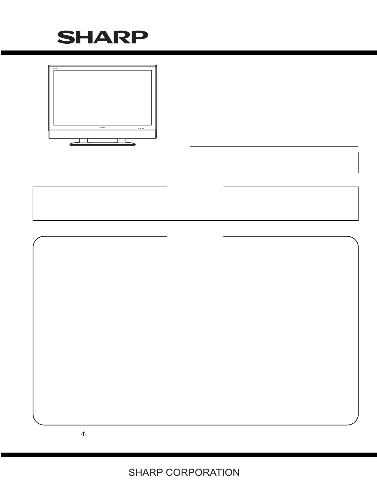
LC-60C46U
TopPage
SUPPLEMENT ATTACHED
LC-60C46U
SERVICE MANUAL
No. S17B3LC60C46U
LCD COLOR TELEVISION
MODEL
In the interests of user-safety (Required by safety regulations in some countries) the set should
be restored to its original condition and only parts identical to those specified should be used.
LC-60C46U
OUTLINE
This model is based on the LC-46D62U and is changed some parts. This Service Manual covers the modifications
alone. For the other points, refer to the LC-46/52D62U Service Manual.
CONTENTS
DIFFERENCES FROM BASE MODEL
LIST OF CHANGED PARTS...............................i
SAFETY PRECAUTION
IMPORTANT SERVICE SAFETY PRE-
CAUTION ...........................................................ii
PRECAUTIONS A PRENDRE LORS DE
LA REPARATION.............................................. iii
PRECAUTIONS FOR USING LEAD-FREE
SOLDER ........................................................... iv
Parts Guide
CHAPTER 1. SPECIFICATIONS
[1] SPECIFICATIONS ......................................... 1-1
CHAPTER 2. OPERATION MANUAL
[1] OPERATION MANUAL .................................. 2-1
CHAPTER 3. DIMENSIONS
[1] DIMENSIONS ................................................ 3-1
CHAPTER 4. REMOVING OF MAJOR PARTS
[1] REMOVING OF MAJOR PARTS ................... 4-1
Parts marked with " " are important for maintaining the safety of the set. Be sure to replace these parts with specified ones for maintaining the
safety and performance of the set.
This document has been published to be used for
after sales service only.
The contents are subject to change without notice.
LC-60C46U
LC-60C46U
DIFFERENCES FROM BASE MODEL
Service Manual
LIST OF CHANGED PARTS
Ref. No. Description LC-46D62U LC-60C46U Note
PWB ASSEMBLIES
R/C, LED Unit DUNTKD909FM02 ← —
KEY Unit DUNTKD910FM02 ← —
MAIN Unit DUNTKD934FM01 DUNTKD934FM07 No Internal parts change
TERMINAL Unit DUNTKD935FM01 DUNTKD935FM07 No Internal parts change
POWER SUPPLY Unit RDENCA184WJQZ ← —
CABINET AND MECHANICAL PARTS
Please refer to a Parts list.
PACKING PARTS, ACCESSORIES AND SERVICE JIGS
Please refer to a Parts list.
i
LC-60C46U
LC-60C46U
SAFETY PRECAUTION
Service Manual
IMPORTANT SERVICE SAFETY PRECAUTION
Service work should be performed only by qualified service technicians who are thoroughly familiar with all safety checks and the
servicing guidelines which follow:
WARNING
1. For continued safety, no modification of any circuit should be
attempted.
2. Disconnect AC power before servicing.
CAUTION: FO R C O N TI NU ED PROTECTION
AGAINST A RISK OF FIRE REPLACE ONLY WITH
SAME TYPE FUSE.
F701 (250V, 8A), F702 (250V, 1A)
F4702 (250V, 4A)
F4701/F4703 (250V, 3A, 127
O
C)
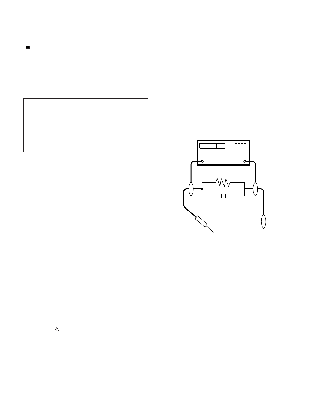
• Use an AC voltmeter having with 5000 ohm per volt, or higher, sensitivity or measure the AC voltage drop across the resistor.
• Connect the resistor connection to all exposed metal parts having a
return to the chassis (antenna, metal cabinet, screw heads, knobs
and control shafts, escutcheon, etc.) and measure the AC voltage
drop across the resistor.
All checks must be repeated with the AC cord plug connection
reversed. (If necessary, a nonpolarized adaptor plug must be used
only for the purpose of completing these checks.)
Any reading of 0.75 Vrms (this corresponds to 0.5 mA rms AC.) or
more is excessive and indicates a potential shock hazard which
must be corrected before returning the monitor to the owner.
DVM
BEFORE RETURNING THE RECEIVER (Fire &
Shock Hazard)
Before returning the receiver to the user, perform the following
safety checks:
3. Inspect all lead dress to make certain that leads are not pinched,
and check that hardware is not lodged between the chassis and
other metal parts in the receiver.
4. Inspect all protective devices such as non-metallic control knobs,
insulation materials, cabinet backs, adjustment and compartment
covers or shields, isolation resistor-capacitor networks, mechanical
insulators, etc.
5. To be sure that no shock hazard exists, check for leakage current in
the following manner.
• Plug the AC cord directly into a 120 volt AC outlet.
• Using two clip leads, connect a 1.5k ohm, 10 watt resistor paralleled by a 0.15µF capacitor in series with all exposed metal cabinet
parts and a known earth ground, such as electrical conduit or electrical ground connected to an earth ground.
///////////////////////////////////////////////////////////////////////////////////////////////////////////////////////////////////////////////////////////////////////////////////////////////////////////////////////////////////////////
TO EXPOSED
METAL PARTS
AC SCALE
1.5k ohm
10W
0.15µF
TEST PROBE
CONNECT TO
KNOWN EARTH
GROUND
SAFETY NOTICE
Many electrical and mechanical parts in LCD color television have
special safety-related characteristics.
These characteristics are often not evident from visual inspection, nor
can protection afforded by them be necessarily increased by using
replacement components rated for higher voltage, wattage, etc.
Replacement parts which have these special safety characteristics are
identified in this manual; electrical components having such features
are identified by " " and shaded areas in the Replacement Parts List
and Schematic Diagrams.
///////////////////////////////////////////////////////////////////////////////////////////////////////////////////////////////////////////////////////////////////////////////////////////////////////////////////////////////////////////
For continued protection, replacement parts must be identical to those
used in the original circuit.
The use of a substitute replacement parts which do not have the same
safety characteristics as the factory recommended replacement parts
shown in this service manual, may create shock, fire or other hazards.
ii
LC-60C46U
PRECAUTIONS A PRENDRE LORS DE LA REPARATION
Ne peut effectuer la réparation qu' un technicien spécialisé qui s'est parfaitement accoutumé à toute vérification de sécurité et aux
conseils suivants.
•
AVERTISSEMENT
1.
N'entreprendre aucune modification de tout circuit. C'est dangereux.
2.
Débrancher le récepteur avant toute réparation.
PRECAUTION:POURLAPROTECTIONCONTINUE CONTRE LES RISQUES D'INCENDIE,
REMPLACER LE FUSIBLE
F701 (250V, 8A), F702 (250V, 1A)
F4702 (250V, 4A)
F4701/F4703 (250V, 3A, 127
O
C)
VERIFICATIONS CONTRE L'INCEN-DIE ET LE
CHOC ELECTRIQUE
Avant de rendre le récepteur à l'utilisateur, effectuer les vérifications suivantes.
Inspecter tous les faisceaux de câbles pour s'assurer que les fils
3.
ne soient pas pincés ou qu'un outil ne soit pas placé entre le châssis et les autres pièces métalliques du récepteur.
4.
Inspecter tous les dispositifs de protection comme les boutons de
commande non-métalliques, les isolants, le dos du coffret, les couvercles ou blindages de réglage et de compartiment, les réseaux
de résistancecapacité, les isolateurs mécaniques, etc.
5.
S'assurer qu'il n'y ait pas de danger d'électrocution en vérifiant la
fuite de courant, de la facon suivante:
•
Brancher le cordon d'alimentation directem-ent à une prise de courant de 120V. (Ne pas utiliser de transformateur d'isolation pour
cet essai).
A l'aide de deux fils à pinces, brancher une résistance de 1.5 kΩ
10 watts en parallèle avec un condensateur de 0.15µF en série
avec toutes les pièces métalliques exposées du coffret et une terre
connue comme une conduite électrique ou une prise de terre
branchée à la terre.
•
Utiliser un voltmètre CA d'une sensibilité d'au moins 5000Ω/V pour
mesurer la chute de tension en travers de la résistance.
•
Toucher avec la sonde d'essai les pièces métalliques exposées qui
présentent une voie de retour au châssis (antenne, coffret métallique, tête des vis, arbres de commande et des boutons, écusson,
etc.) et mesurer la chute de tension CA en-travers de la résistance.
Toutes les vérifications doivent être refaites après avoir inversé la
fiche du cordon d'alimentation. (Si nécessaire, une prise
d'adpatation non polarisée peut être utilisée dans le but de terminer ces vérifications.)
La tension de pointe mesurèe ne doit pas dépasser 0.75V (correspondante au courant CA de pointe de 0.5mA).
Dans le cas contraire, il y a une possibilité de choc électrique qui
doit être supprimée avant de rendre le récepteur au client.
DVM
ECHELLE CA
1.5k ohm
10W
µ
F
0.15
SONDE D'ESSAI
AUX PIECES
METALLIQUES
EXPOSEES
/////////////////////////////////////////////////////////////////////////////////////////////////////////////////////////////////////////////////////////////////////////////////////////////////////////////////////////////////////////////
BRANCHER A UNE
TERRE CONNUE
AVIS POUR LA SECURITE
De nombreuses pièces, électriques et mécaniques, dans les téléviseur ACL présentent des caractéristiques spéciales relatives à la sécurité, qui ne sont souvent pas évidentes à vue. Le degré de protection ne peut pas être nécessairement augmentée en utilisant des
pièces de remplacement étalonnées pour haute tension, puissance,
etc.
Les pièces de remplacement qui présentent ces caractéristiques sont
identifiées dans ce manuel; les pièces électriques qui présentent ces
particularités sont identifiées par la marque " " et hachurées dans la
liste des pièces de remplacement et les diagrammes schématiques.
/////////////////////////////////////////////////////////////////////////////////////////////////////////////////////////////////////////////////////////////////////////////////////////////////////////////////////////////////////////////
Pour assurer la protection, ces pièces doivent être identiques à celles
utilisées dans le circuit d'origine. L'utilisation de pièces qui n'ont pas
les mêmes caractéristiques que les pièces recommandées par l'usine,
indiquées dans ce manuel, peut provoquer des électrocutions, incendies, radiations X ou autres accidents.
iii
LC-60C46U
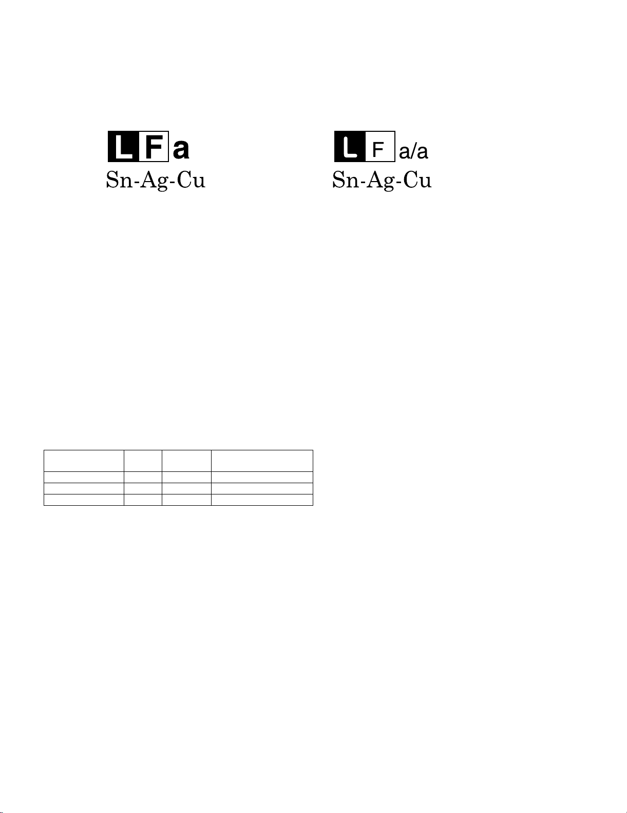
PRECAUTIONS FOR USING LEAD-FREE SOLDER
Employing lead-free solder
• “PWBs” of this model employs lead-free solder. The LF symbol indicates lead-free solder, and is attached on the PWBs and service manuals. The
alphabetical character following LF shows the type of lead-free solder.
Example:
Indicates lead-free solder of tin, silver and copper. Indicates lead-free solder of tin, silver and copper.
Using lead-free wire solder
• When fixing the PWB soldered with the lead-free solder, apply lead-free wire solder. Repairing with conventional lead wire solder may cause damage or accident due to cracks.
As the melting point of lead-free solder (Sn-Ag-Cu) is higher than the lead wire solder by 40 °C, we recommend you to use a dedicated soldering
bit, if you are not familiar with how to obtain lead-free wire solder or soldering bit, contact our service station or service branch in your area.
Soldering
• As the melting point of lead-free solder (Sn-Ag-Cu) is about 220 °C which is higher than the conventional lead solder by 40 °C, and as it has poor
solder wettability, you may be apt to keep the soldering bit in contact with the PWB for extended period of time. However, Since the land may be
peeled off or the maximum heat-resistance temperature of parts may be exceeded, remove the bit from the PWB as soon as you confirm the
steady soldering condition.
Lead-free solder contains more tin, and the end of the soldering bit may be easily corroded. Make sure to turn on and off the power of the bit as
required.
If a different type of solder stays on the tip of the soldering bit, it is alloyed with lead-free solder. Clean the bit after every use of it.
When the tip of the soldering bit is blackened during use, file it with steel wool or fine sandpaper.
• Be careful when replacing parts with polarity indication on the PWB silk.
Lead-free wire solder for servicing
PARTS CODE
ZHNDAi123250E BL J φ0.3mm 250g (1roll)
ZHNDAi126500E BK J φ0.6mm 500g (1roll)
ZHNDAi12801KE BM J φ1.0mm 1kg (1roll)
PRICE
RANK
PART
DELIVERY
DESCRIPTION
iv
LC-60C46U
LC-60C46U
CHAPTER 1. SPECIFICATIONS
[1] SPECIFICATIONS
Service Manual
Item
LCD panel
Number of dots
TV-standard (CCIR)
TV
Function
Receiving
Channel
Audio multiplex
Audio out
Terminals
Rear
VHF/UHF
CATV
Digital Terrestrial
Broadcast (8VSB)
Digital cable
(64/256 QAM)
INPUT 1
INPUT 2
INPUT 3
INPUT 4
INPUT 5
Model: LC-60C46U
46" Advanced Super View & BLACK TFT
LCD
6,220,800 dots (1920 1080 3 dots)
American TV Standard ATSC/NTSC System
VHF 2-13ch, UHF 14-69ch
1-135ch (non-scrambled channel only)
2-69ch
1
*
1-135ch (non-scrambled channel only)
BTSC System
15W 2
AV in, COMPONENT in
AV in, COMPONENT in
S-VIDEO in, AV in
Audio in, HDMI in with HDCP
HDMI in with HDCP
OSD language
Power Requirement
ANTENNA
DIGITAL AUDIO OUTPUT
OUTPUT
75 Unbalance, F Type
Optical Digital audio output 1 (PCM/Dolby Digital)
Audio out
English/French/Spanish
AC 120 V, 60 Hz (FOR NORTH AMERICA)
1 for Analog (VHF/UHF/CATV) and Digital (AIR/CABLE)
AC 110-240 V, 50/60 Hz (FOR OTHERS)
Power Consumption
w/o stand
Weight
with stand
Dimension
(W H D)
w/o stand
with stand
Operating temperature
1
*
Emergency alert messages via Cable are unreceivable.
270 W (0.7 W Standby with AC 120V)
70.6 lbs./32.0 kg
78.3 lbs./35.5 kg
27
44
/
3013/
64
27
/
44
++ +
335/
64
32°F to 104°F (0°C to 40°C)
64
64
459/64inch
137/16inch
As part of policy of continuous improvement, SHARP reserves the right to make design and specification changes for product
improvement without prior notice. The performance specification figures indicated are nominal values of production units.
There may be some deviations from these values in individual units.
1 – 1
LC-60C46U
CHAPTER 2. OPERATION MANUAL
[1] OPERATION MANUAL
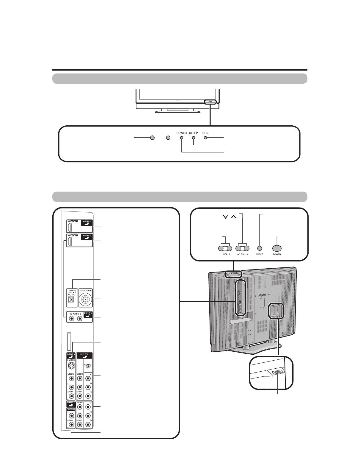
Part names
TV (Front)
LC-60C46U
Service Manual
TV (Rear)
Remote control sensor
OPC sensor*
HDMI terminal (INPUT 5)
HDMI terminal (INPUT 4)
DIGITAL AUDIO OUTPUT terminal
Antenna/Cable in
Channel buttons
(CH /)
Volume
buttons
-
(VOL /)
+
OPC indicator*
SLEEP indicator**
POWER indicator**
INPUT button
POWER button
AUDIO terminal (INPUT 4)
INPUT 3 terminals
INPUT 1 terminals
INPUT 2 terminals
AUDIO OUTPUT terminals
AC INPUT terminal
2 – 1
LC-60C46U
Part names
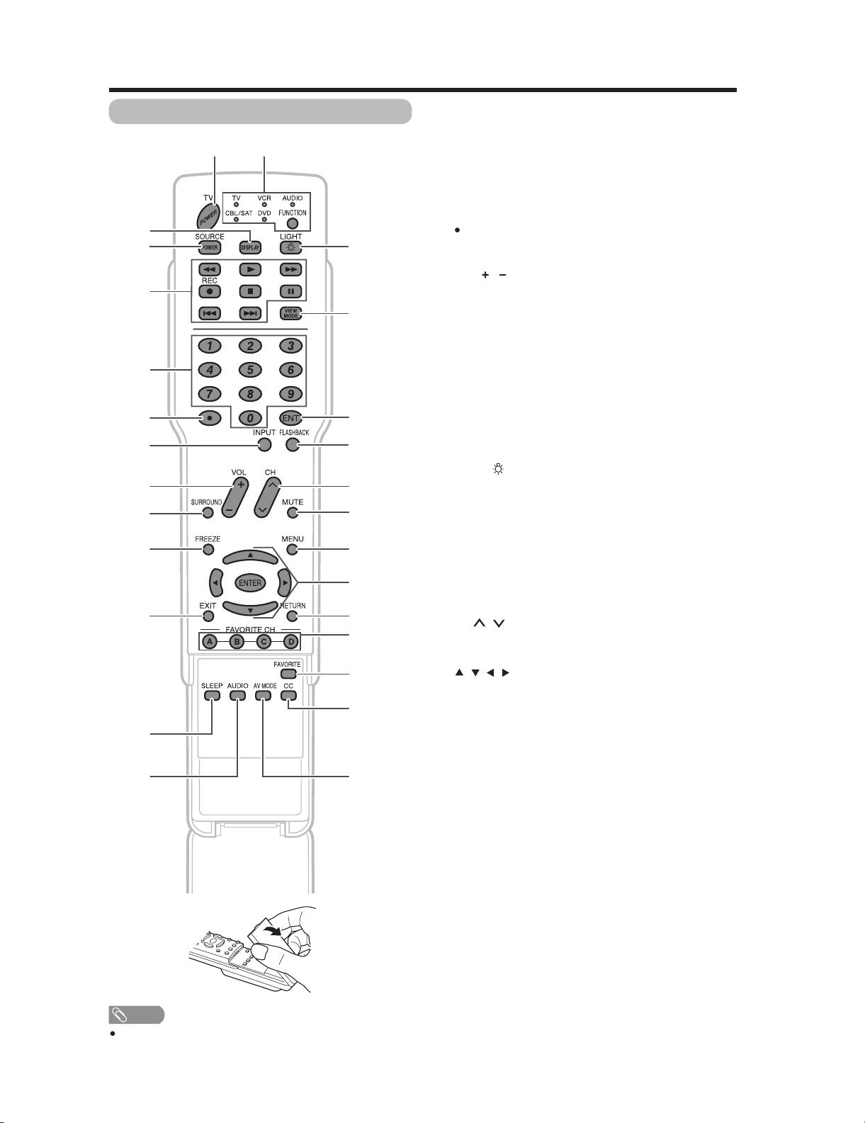
Remote control unit
114
2
3
4
5
6
7
8
9
10
11 23
12
13 27
15
16
17
18
19
20
21
22
24
25
26
1 TV POWER: Switch the TV power on or enters standby
mode.
2 DISPLAY: Display the channel information.
3 SOURCE POWER: Turns the power of the external
equipment on and off.
4 External equipment operational buttons: Operate the
external equipment.
50_9: Set the channel.
6 (DOT):
7INPUT:Select a TV input source. (TV, INPUT 1, INPUT 2,
INPUT 3, INPUT 4, INPUT 5)
8VOL/:Set the volume.
9 SURROUND: Select Surround settings.
10 FREEZE: Set the still image. Press again to return to
normal screen.
11 EXIT: Turn off the menu screen.
12 SLEEP:Set the sleep timer.
13 AUDIO: Selects the MTS/SAP or the audio mode during
multi-channel audio broadcasts.
14 FUNCTION: Switches the remote control for TV, CBL/
SAT, VCR, DVD and AUDIO operation. Indicator lights up
for the current mode.
* To enter the code registration mode, you need to press
FUNCTION and DISPLAY at the same time.
15 LIGHT : When pressed all buttons on the remote
control unit will light. The lighting will turn off if no
operations are performed within about 5 seconds. This
button is used for performing operations in low-light
situations.
16 VIEW MODE: Select the screen size.
17 ENT: Jumps to a channel after selecting with the 0_9
buttons.
18 FLASHBACK:Return to the previous channel or external
input mode.
19
CH / : Select the channel.
20 MUTE: Mute the sound.
21 MENU: Display the menu screen.
22 ////ENTER: Select a desired item on the
screen.
23 RETURN: Return to the previous menu screen.
24 FAVORITE CH
A, B, C, D: Select 4 preset favorite channels in 4 different
categories.
While watching, you can toggle the selected channels by
pressing A, B, C and D.
25 FAVORITE:Register favorite channel.
26 CC: Display captions from a closed-caption source.
NOTE
When using the remote control unit, point it at the TV.
27 AV MODE: Select an audio or video setting. (When the
input source is TV, INPUT 1, 2 or 3: STANDARD, MOVIE,
GAME, USER, DYNAMIC (Fixed), DYNAMIC. When
the input source is INPUT 4 or 5: STANDARD, MOVIE,
GAME, PC, USER, DYNAMIC (Fixed), DYNAMIC)
2 – 2
LC-60C46U
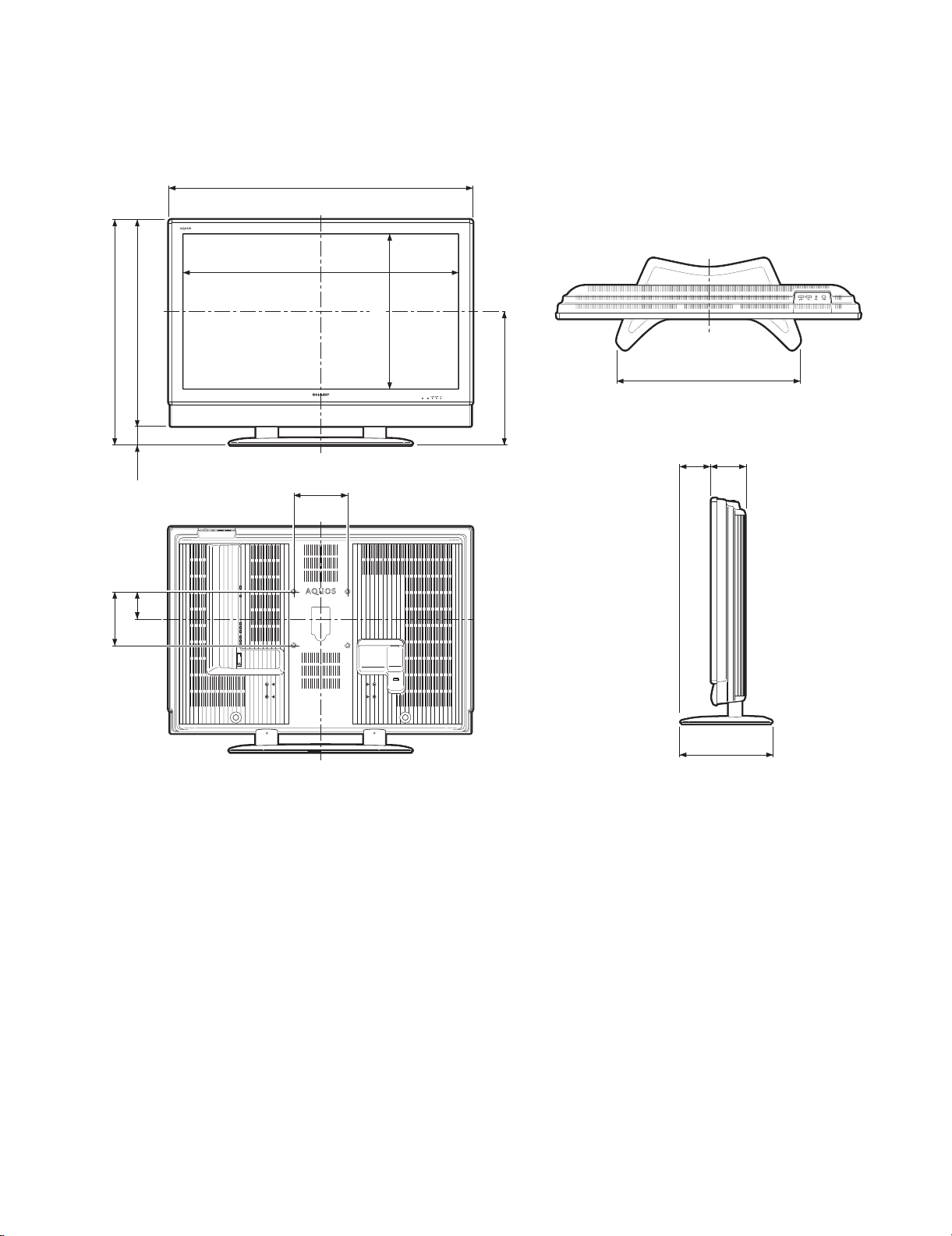
CHAPTER 3. DIMENSIONS
[1] DIMENSIONS
LC-60C46U
Service Manual
840)
(
64
/
5
33
(200)
8
/
7
7
767)
(
64
/
13
30
(73)
8
/
7
2
(100)
64
/
61
3
40
7
/32(
27
44
1021.4)
/64(1128)
77/8(200)
575.4)
(
32
/
21
22
498)
(
8
/
5
19
Unit: inch/(mm)
2613/16(681)
59
/64(125)45/8(117)
4
13
7
/16(341)
3 – 1
 Loading...