

Sew Eurodrive MOVIMOT MM-D Operating Instructions
Drive Technology \ Drive Automation \ System Integration \ Services
Operating Instructions
MOVIMOT
®
MM..D
With DRS/DRE/DRP AC Motor
Edition 12/2010 17000017 / EN

SEW-EURODRIVE—Driving the world

Contents
Contents
1 General Information ............................................................................................ 6
1.1 How to use this documentation................................................................... 6
1.2 Structure of the safety notes ....................................................................... 6
1.3 Rights to claim under limited warranty ........................................................ 7
1.4 Exclusion of liability..................................................................................... 7
1.5 Copyright..................................................................................................... 7
1.6 Product names and trademarks.................................................................. 7
2 Safety Notes ........................................................................................................ 8
2.1 Preliminary information ............................................................................... 8
2.2 General information .................................................................................... 8
2.3 Target group ............................................................................................... 8
2.4 Designated use ........................................................................................... 9
2.5 Other applicable documentation ................................................................. 9
2.6 Transportation, storage............................................................................. 10
2.7 Installation................................................................................................. 10
2.8 Electrical connection ................................................................................. 10
2.9 Safe disconnection.................................................................................... 10
2.10 Operation .................................................................................................. 11
3 Unit Design ........................................................................................................ 12
3.1 MOVIMOT
3.2 MOVIMOT
3.3 Type designation of MOVIMOT
3.4 Type designation of MOVIMOT
3.5 Type designation of the variant "mounted close to the motor".................. 17
4 Mechanical Installation..................................................................................... 18
4.1 MOVIMOT
4.2 Installation of MOVIMOT
4.3 Installation of the MOVIMOT
4.4 Tightening torques .................................................................................... 28
5 Electrical Installation ........................................................................................ 30
5.1 Installation instructions.............................................................................. 30
5.2 Connection of the MOVIMOT
5.3 MOVIMOT
5.4 Connection between MOVIMOT
when mounted close to the motor............................................................. 38
5.5 Connection of the MOVIMOT
5.6 Connection of RS-485 bus master............................................................ 53
5.7 Connecting the DBG keypad .................................................................... 54
5.8 PC connection........................................................................................... 55
®
drive...................................................................................... 12
®
inverter.................................................................................. 13
®
drive...................................................... 15
®
inverter ................................................. 16
®
gearmotor installation ........................................................... 18
®
options............................................................ 20
®
inverter close to the motor........................ 27
®
drive......................................................... 36
®
plug connectors .................................................................... 37
®
and motor
®
options .................................................... 42
Operating Instructions – MOVIMOT® MM..D with DRS/DRE/DRP AC Motor
3

Contents
6 "Easy" Startup................................................................................................... 56
6.1 Overview ................................................................................................... 56
6.2 Important notes on startup ........................................................................ 57
6.3 Requirements............................................................................................ 58
6.4 Description of control elements................................................................. 58
6.5 Description of the DIP switches S1........................................................... 61
6.6 Description of DIP switches S2................................................................. 63
6.7 Selectable additional functions MM..D-503-00 ......................................... 67
6.8 Startup with binary control ........................................................................ 91
6.9 Startup with options MBG11A or MLG..A ................................................. 93
6.10 Startup with MWA21A option .................................................................... 95
6.11 Startup with MWF11A option .................................................................... 98
6.12 Supplementary notes for installation close to the motor ........................ 100
7 "Easy" Startup with RS-485 Interface/Fieldbus............................................ 103
7.1 Important notes on startup ...................................................................... 103
7.2 Requirements.......................................................................................... 104
7.3 Startup procedure ................................................................................... 104
7.4 Coding of process data ........................................................................... 106
7.5 Function with RS-485 master.................................................................. 111
8 "Expert" Startup with Parameter Function ................................................... 116
8.1 Important notes on startup ...................................................................... 116
8.2 Requirements.......................................................................................... 117
8.3 MOVITOOLS
8.4 Startup and function expansion with individual parameters.................... 119
8.5 Startup and configuration with a central controller and MQP.................. 122
8.6 Startup by transferring the set of parameters ......................................... 123
8.7 Parameter list.......................................................................................... 125
8.8 Parameter description............................................................................. 131
9 Operation ......................................................................................................... 151
9.1 Operating display .................................................................................... 151
9.2 Drive ID module ...................................................................................... 152
9.3 Keypads .................................................................................................. 153
9.4 MWA21A setpoint converter ................................................................... 154
9.5 MWF11A setpoint converter ................................................................... 155
9.6 MOVIMOT
9.7 DBG keypad............................................................................................ 164
®
MotionStudio................................................................... 117
®
manual operation with MOVITOOLS® MotionStudio .......... 160
4
Operating Instructions – MOVIMOT® MM..D with DRS/DRE/DRP AC Motor

Contents
10 Service ............................................................................................................. 172
10.1 Status and error display .......................................................................... 172
10.2 Inspection/maintenance .......................................................................... 176
10.3 Diagnostics with MWF11A option ........................................................... 177
10.4 Unit replacement..................................................................................... 178
10.5 Rotating the connection box ................................................................... 180
10.6 SEW Service........................................................................................... 182
10.7 Shut down ............................................................................................... 182
10.8 Storage ................................................................................................... 183
10.9 Extended storage.................................................................................... 183
10.10 Disposal .................................................................................................. 183
11 Technical Data................................................................................................. 184
11.1 Motor with operating point 400 V / 50 Hz or 400 V / 100 Hz................... 184
11.2 Motor with operating point 460 V / 60 Hz................................................ 186
11.3 Motor with operating point 230 V / 60 Hz................................................ 188
11.4 Technical data of options & accessories................................................. 190
11.5 Work done, working air gap and braking torque of the brake ................. 195
11.6 Braking torque assignment ..................................................................... 195
11.7 Integrated RS-485 interface.................................................................... 196
11.8 Diagnostics interface............................................................................... 196
11.9 Assignment of internal braking resistors ................................................. 196
11.10 Assignment of external braking resistors ................................................ 197
11.11 Resistance and assignment of the brake coil ......................................... 197
11.12 Assignment of the Drive-ID module ........................................................ 198
12 Declaration of Conformity .............................................................................. 199
13 Address List .................................................................................................... 200
Index................................................................................................................. 210
Operating Instructions – MOVIMOT® MM..D with DRS/DRE/DRP AC Motor
5
1
General Information
How to use this documentation
1 General Information
1.1 How to use this documentation
The documentation is an integral part of the product and contains important information
on operation and service. The documentation is written for all employees who assemble,
install, startup, and service this product.
The documentation must be accessible and legible. Make sure that persons responsible
for the system and its operation, as well as persons who work independently on the unit,
have read through the documentation carefully and understood it. If you are unclear
about any of the information in this documentation, or if you require further information,
contact SEW-EURODRIVE.
1.2 Structure of the safety notes
1.2.1 Meaning of the signal words
The following table shows the grading and meaning of the signal words for safety notes,
notes on potential risks of damage to property, and other notes.
Signal word Meaning Consequences if disregarded
DANGER Imminent danger Severe or fatal injuries
WARNING Possible dangerous situation Severe or fatal injuries
CAUTION Possible dangerous situation Minor injuries
NOTICE Possible damage to property Damage to the drive system or its envi-
INFORMATION Useful information or tip: Simpli-
fies the handling of the drive
system.
1.2.2 Structure of the section-related safety notes
Section safety notes do not apply to a specific action, but to several actions pertaining
to one subject. The used symbols indicate either a general or a specific hazard.
This is the formal structure of a section safety note:
SIGNAL WORD
Type and source of danger.
Possible consequence(s) if disregarded.
• Measure(s) to prevent the danger.
1.2.3 Structure of the embedded safety notes
Embedded safety notes are directly integrated in the instructions just before the description of the dangerous action.
ronment
This is the formal structure of an embedded safety note:
• SIGNAL WORD Nature and source of hazard.
Possible consequence(s) if disregarded.
– Measure(s) to prevent the danger.
6
Operating Instructions – MOVIMOT® MM..D with DRS/DRE/DRP AC Motor

Rights to claim under limited warranty
1.3 Rights to claim under limited warranty
A requirement of fault-free operation and fulfillment of any rights to claim under limited
warranty is that you adhere to the information in the documentation. Read the documentation before you start working with the unit!
1.4 Exclusion of liability
General Information
1
You must comply with the information contained in this documentation to ensure safe
operation of MOVIMOT
formance features. SEW-EURODRIVE assumes no liability for injury to persons or damage to equipment or property resulting from non-observance of these operating instructions. In such cases, any liability for defects is excluded.
®
1.5 Copyright
© 2010 – SEW-EURODRIVE. All rights reserved.
Unauthorized duplication, modification, distribution or any other use of the whole or any
part of this documentation is strictly prohibited.
1.6 Product names and trademarks
All brands and product names in this documentation are trademarks or registered trademarks of their respective titleholders.
and to achieve the specified product characteristics and per-
Operating Instructions – MOVIMOT® MM..D with DRS/DRE/DRP AC Motor
7

2
Safety Notes
Preliminary information
2 Safety Notes
The following basic safety notes must be read carefully to prevent injury to persons and
damage to property. The operator must ensure that the basic safety notes are read and
adhered to. Make sure that persons responsible for the plant and its operation, as well
as persons who work independently on the unit, have read through the operating instructions carefully and understood them. If you are unclear about any of the information in
this documentation or if you require further information, please contact SEWEURODRIVE.
2.1 Preliminary information
The following safety notes are primarily concerned with the use of MOVIMOT® drives.
If you use other SEW components, also refer to the safety notes for the respective components in the corresponding documentation.
Please also observe the supplementary safety notes in the individual chapters of this
documentation.
2.2 General information
Never install or start up damaged products. Submit a complaint to the shipping company
immediately in the event of damage.
During operation, MOVIMOT
as well as hot surfaces, depending on their enclosure.
Removing covers without authorization, improper use as well as incorrect installation or
operation may result in severe injuries to persons or damage to property. Refer to the
documentation for additional information.
2.3 Target group
Only qualified personnel is authorized to install, startup or service the units or correct
unit faults (observing IEC 60364 and/or CENELEC HD 384 or DIN VDE 0100 and IEC
60664 or DIN VDE 0110 as well as national accident prevention guidelines).
Qualified personnel in the context of these basic safety notes are persons familiar with
installation, assembly, startup and operation of the product who possess the necessary
qualifications.
Any activities regarding transportation, storage, operation, and disposal must be carried
out by persons who have been instructed appropriately.
®
drives can have live, bare and movable or rotating parts
8
Operating Instructions – MOVIMOT® MM..D with DRS/DRE/DRP AC Motor

2.4 Designated use
MOVIMOT® inverters are components intended for installation in electrical systems or
machines.
In case of installation in machines, startup of MOVIMOT
nated operation) is prohibited until it is determined that the machine meets the requirements stipulated in the Machinery Directive 2006/42/EC.
Startup (i.e. the start of designated use) is only permitted under observance of the EMC
directive 2004/108/EC.
MOVIMOT
EC. The standards given in the declaration of conformity are used for the MOVIMOT
inverter.
You must observe the technical data and information on the connection requirements
as provided on the nameplate and in the documentation.
2.4.1 Safety functions
The MOVIMOT
described and expressly permitted.
Safety Notes
Designated use
®
inverters (i.e. start of desig-
®
inverters comply with the regulations of the Low Voltage Directive 2006/95/
®
inverter may not perform safety functions unless these functions are
2
®
2.4.2 Hoist applications
MOVIMOT
sec. "Additional function 9" (page 78).
MOVIMOT
®
inverters are suitable for hoist applications to a limited degree only, see
®
inverters are not designed for use as a safety device in hoist applications.
2.5 Other applicable documentation
Note also the following documentation:
•"MOVIMOT
• "DR.71-225, 315 AC Motors" operating instructions
• Operating instructions for the gear unit (only for MOVIMOT
You can download or order these publications on the Internet (http://www.sew-euro-
drive.de, under the heading "Documentation").
®
Gearmotors" catalog
®
gearmotors)
Operating Instructions – MOVIMOT® MM..D with DRS/DRE/DRP AC Motor
9

2
Safety Notes
Transportation, storage
2.6 Transportation, storage
You must observe the notes on transportation, storage and proper handling. Comply
with the requirements for climatic conditions stated in chapter "Technical Data". Tighten
installed eyebolts securely. They are designed for the weight of the MOVIMOT
Do not attach any additional loads. Use suitable, sufficiently rated handling equipment
(e.g. rope guides) if required.
2.7 Installation
The units must be installed and cooled according to the regulations and specifications
in the corresponding documentation.
Protect the MOVIMOT
The following applications are prohibited unless the unit is explicitly designed for such
use:
• Use in potentially explosive atmospheres.
• Use in areas exposed to harmful oils, acids, gases, vapors, dust, radiation, etc.
• Use in non-stationary applications with strong mechanical oscillation and impact
®
inverters from improper strain.
loads; see chapter "Technical Data".
®
drive.
2.8 Electrical connection
Observe the applicable national accident prevention guidelines when working on live
MOVIMOT
Perform electrical installation according to the pertinent regulations (e.g. cable cross
sections, fusing, protective conductor connection). For any additional information, refer
to the applicable documentation.
For notes on EMC compliant installation, such as shielding, grounding, arrangement of
filters and routing of lines, refer to chapter "Installation instructions". The manufacturer
of the system or machine is responsible for maintaining the limits established by EMC
legislation.
Protective measures and protection devices must comply with the regulations in force
(e.g. EN 60204 or EN 61800-5-1).
A voltage test according to EN 61800-5-1:2007 chapter 5.2.3.2 is required for the
MOVIMOT
®
®
2.9 Safe disconnection
MOVIMOT® inverters meet all requirements for safe disconnection of power and electronic connections in accordance with EN 61800-5-1. All connected circuits must also
satisfy the requirements for safe disconnection.
drive inverters (e.g. BGV A3).
drives prior to startup in order to ensure the insulation.
10
Operating Instructions – MOVIMOT® MM..D with DRS/DRE/DRP AC Motor

2.10 Operation
Safety Notes
Operation
Systems with integrated MOVIMOT® inverters must be equipped with additional monitoring and protection devices according to the applicable safety guidelines, such as the
law governing technical equipment, accident prevention regulations, etc. Additional protective measures may be necessary for applications with increased potential risk.
Do not touch live components and power connections immediately after separation of
the MOVIMOT
charged capacitors. Wait at least for 1 minute after having switched off the supply voltage.
As soon as supply voltages are present at the MOVIMOT
must be closed (i.e. the MOVIMOT
brid cable must be connected).
The fact that the status LED and other display elements are no longer illuminated does
not indicate that the unit has been disconnected from the supply system and no longer
carries any voltage.
Mechanical blocking or internal safety functions of the unit can cause a motor standstill.
Eliminating the cause of the problem or performing a reset may result in the drive restarting automatically. If, for safety reasons, this is not permitted for the driven machine,
disconnect the unit from the supply system before correcting the error.
Caution: Danger of burns: The surface temperature of the MOVIMOT
ternal options, e.g. the heat sink of the braking resistor, can exceed 60 °C during operation!
®
inverter from the supply voltage because there may still be some
®
®
inverter and, if applicable, the connector of the hy-
inverter, the connection box
®
drive and of ex-
2
Operating Instructions – MOVIMOT® MM..D with DRS/DRE/DRP AC Motor
11
3
3 Unit Design
3.1 MOVIMOT® drive
Unit Design
MOVIMOT® drive
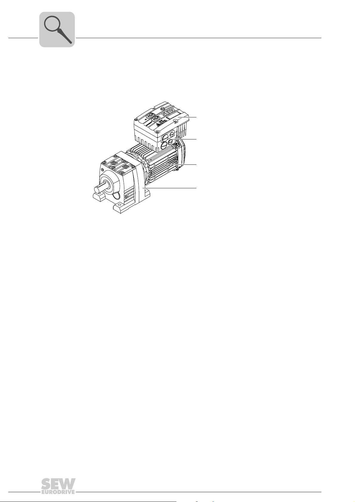
The following figure shows a MOVIMOT® drive with helical gear unit:
[1]
[2]
[3]
[4]
[1] MOVIMOT® inverter
[2] Connection box
[3] Motor
[4] Helical gear unit
A MOVIMOT
• MOVIMOT
– Mounted on the motor (see example above)
– or mounted close to the motor
• Motor (see motor operating instructions)
• Gear unit (optional, see gear unit operating instructions)
®
drive is a combination of:
®
inverter
3531634827
12
Operating Instructions – MOVIMOT® MM..D with DRS/DRE/DRP AC Motor
3.2 MOVIMOT® inverter
[7][6][5] [7][11] [13] [15]
0 1 2 0 1 2
[14] [16][5] [12] [17] [18][8] [9] [10]
[4]
[3][1] [2]
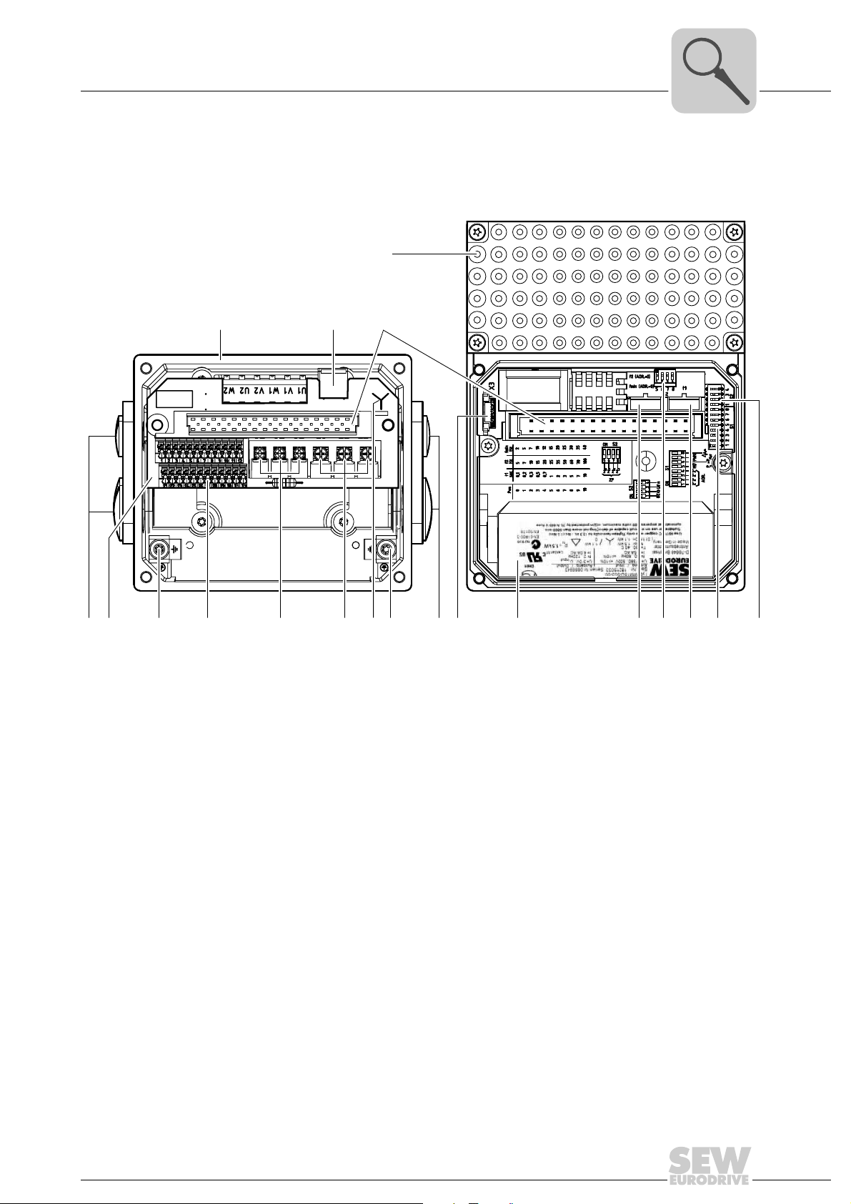
The following figure shows the connection box and the MOVIMOT® inverter:
Unit Design
MOVIMOT® inverter
3
[1] Connection box
[2] X10: Plug connector for BEM option
[3] Plug connector for MOVIMOT
[4] MOVIMOT
[5] Cable glands
[6] Connection unit with terminals
[7] Screw for PE connection
[8] X5, X6: Electronics terminal strips
[9] X1: Connection for brake coil (motors with brake) or braking resistor (motors without brake)
[10] X1: Supply system connection L1, L2, L3
[11] Connection type identification
[12] Drive-ID module
[13] Nameplate of the MOVIMOT
[14] Setpoint switch f2 (green)
[15] DIP switches S2/5 – S2/8
[16] Switch t1 for integrator ramp (white)
[17] DIP switches S1/1 – S1/8
[18] DIP switches S2/1 – S2/4
®
inverter with heat sink
®
inverter
®
inverter
615683595
Operating Instructions – MOVIMOT® MM..D with DRS/DRE/DRP AC Motor
13
3
[4]
[3]
[2]
[1]
Unit Design
MOVIMOT® inverter
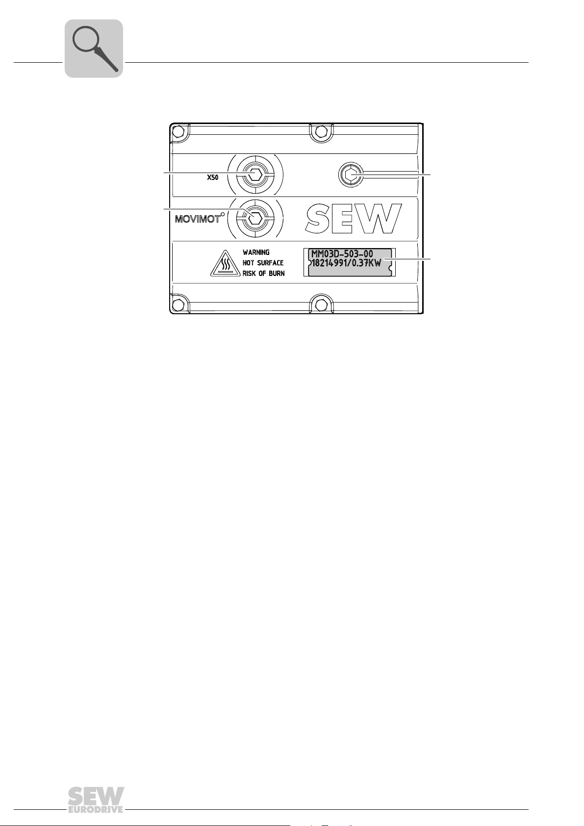
The following figure shows the top of the MOVIMOT® inverter:
514402955
[1] X50: Diagnostics interface with screw plug
[2] Setpoint potentiometer f1 with screw plug
[3] Status LED
[4] Unit identification
14
Operating Instructions – MOVIMOT® MM..D with DRS/DRE/DRP AC Motor
Type designation of MOVIMOT® drive
3.3 Type designation of MOVIMOT® drive
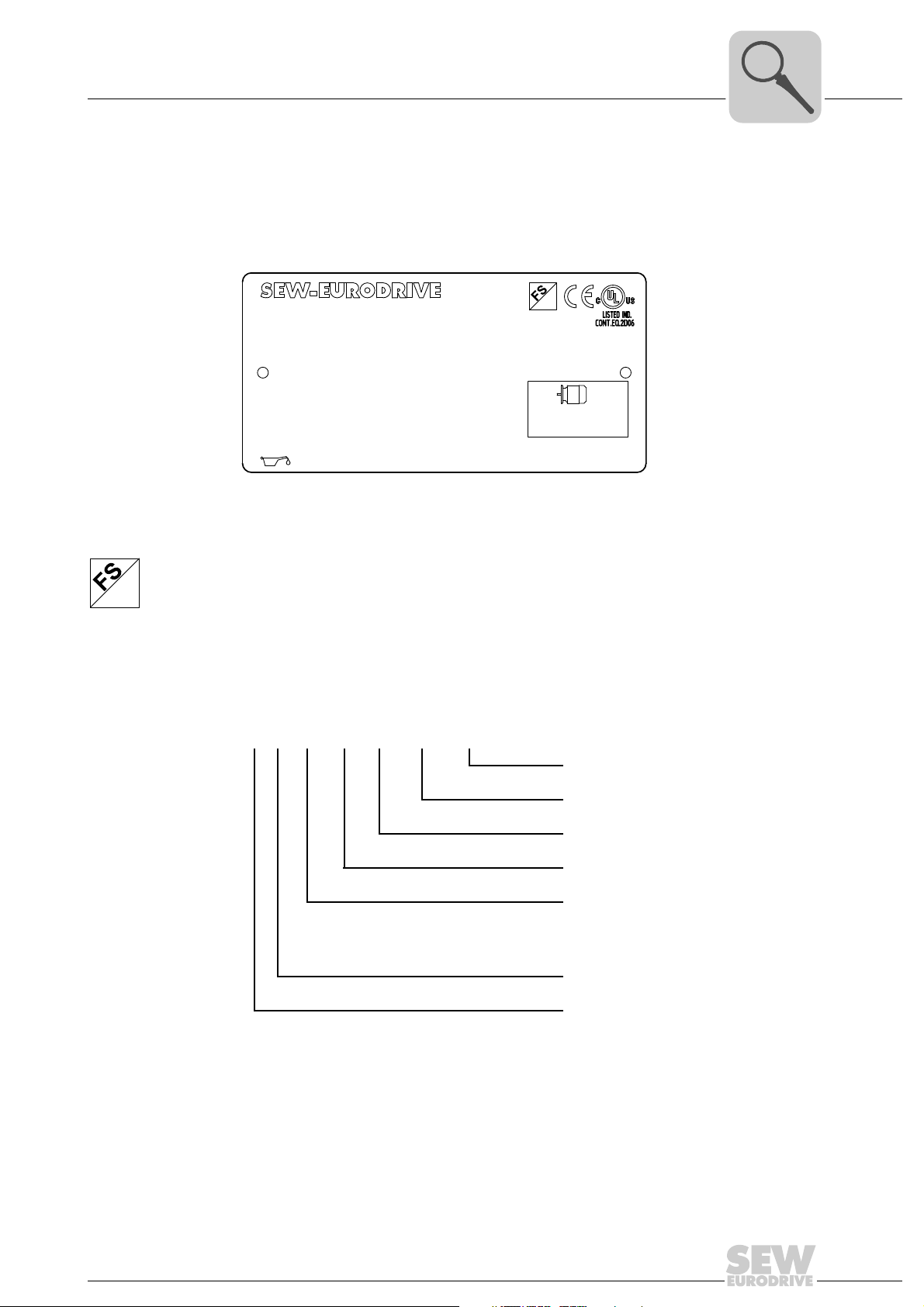
3.3.1 Nameplate
The following figure gives an example of a nameplate of a MOVIMOT
plate is attached to the motor.
Unit Design
®
drive. The name-
3
76646 Bruchsal/Germany
RF47DRE90L4BE2/MM15/MO
01.300123457.0002.06
380-500
V
1.5
kW
16.22 166 54
I
M1
IM
220..240
BR
V
CLP CC VGB220 0.65I
Nm
Nm
Hz
13
Hz 50-60
50
kg
IP
r/min
M.L.
31
A
1400/86 1:5
02
01
-20...40
°C
Iso.Kl.
CT
kW
eff %
Made in Germany
155(F)3.5
TEFC
3~
1.5 50
Hz
85.2
1883410
FS logo The logos at the top of the nameplate are only there if:
• the motor is manufactured accordingly,
01
• and contains at least one safety-rated component.
The FS logo on the nameplate is based on the combination of safety-related components that is installed.
3.3.2 Type designation
The following table shows the type designation of the MOVIMOT
RF 47 DRE 90L4 BE/MM15/MO
Additional feature: inverter
9007199774918155
®
drive:
1)
MOVIMOT® inverter
Optional design motor (brake)
Size, number of poles on motor
Motor series
DRS = DRS motor
DRE = DRE motor
DRP = DRP motor
Gear unit size
Gear unit series
1) The nameplate only displays options installed at the factory.
The available variants are listed in the "MOVIMOT
®
Gearmotors" catalog.
Operating Instructions – MOVIMOT® MM..D with DRS/DRE/DRP AC Motor
15
3
Status:
10 12 -- A -- -- 10 10 12
02 / 08 444
Type :
MM15D-503-00
P# : 18215033
Eingang / Input
U
f
I
T -30 . . . +40°C
I3.5A AC 4.0A AC
f50 ... 60Hz
D-76646 Bruchsal
MOVIMOT
Antriebsumrichter
P-Motor 1.5kW / 2.0HP
Drive Inverter
Use 60/75°C copper wire only. Tighten terminals to 13.3 in.– ibs. (1.5 Nm).
Suitable for use on a circuit capable of delivering not more than 200,000 rms
symmetrical amperes, 500 volts maximum. Integral solid state short crcuit
protection does not provide BCP. BCP must be provided in
accordance with the NEC and any additional local codes.
Made in Germany
2 ... 120Hz
3x0V . . . Uin
U=
=
=
=
=
=
=
3x380 . . . 500V AC
Ausgang / Output
S# : 0886946
CH01
N2936
[2]
[4][3]
[1]
Unit Design
Type designation of MOVIMOT® inverter
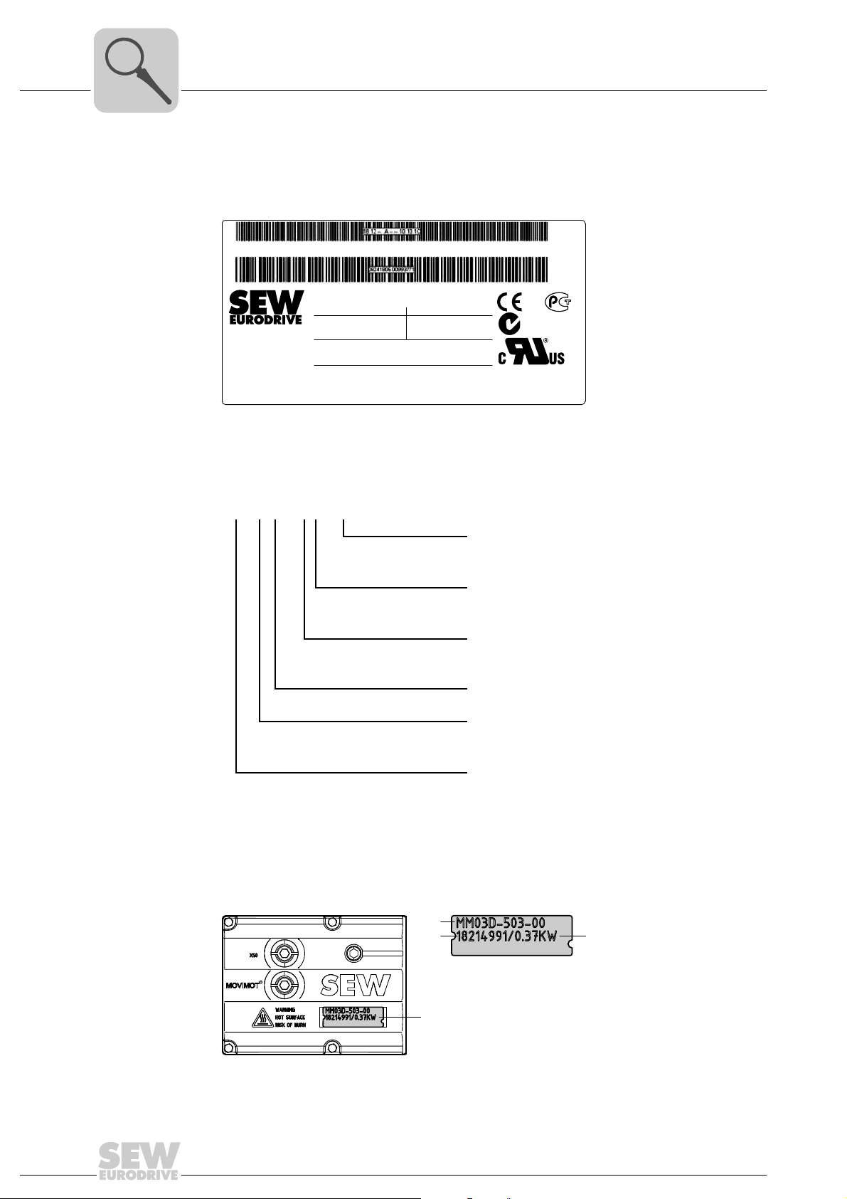
3.4 Type designation of MOVIMOT® inverter
3.4.1 Nameplate
The following figure gives an example of a nameplate of a MOVIMOT
3.4.2 Type designation
The following table shows the type designation of the MOVIMOT
®
inverter:
9007201212668299
®
inverter:
MM 15 D – 503 – 00
The available variants are listed in the "MOVIMOT
3.4.3 Unit identification
The unit identification [1] on the top of the MOVIMOT
about the inverter type [2], inverter part number [3], unit power [4].
Variant
00 = Standard
Connection type
3 = 3-phase
Supply voltage
50 = AC 380 – 500 V
23 = AC 200 – 240 V
Version D
Motor power
15 = 1.5 kW
Unit series
MM = MOVIMOT
®
®
Gearmotors" catalog.
®
inverter provides information
16
457916555
Operating Instructions – MOVIMOT® MM..D with DRS/DRE/DRP AC Motor
Unit Design
Type designation of the variant "mounted close to the motor"
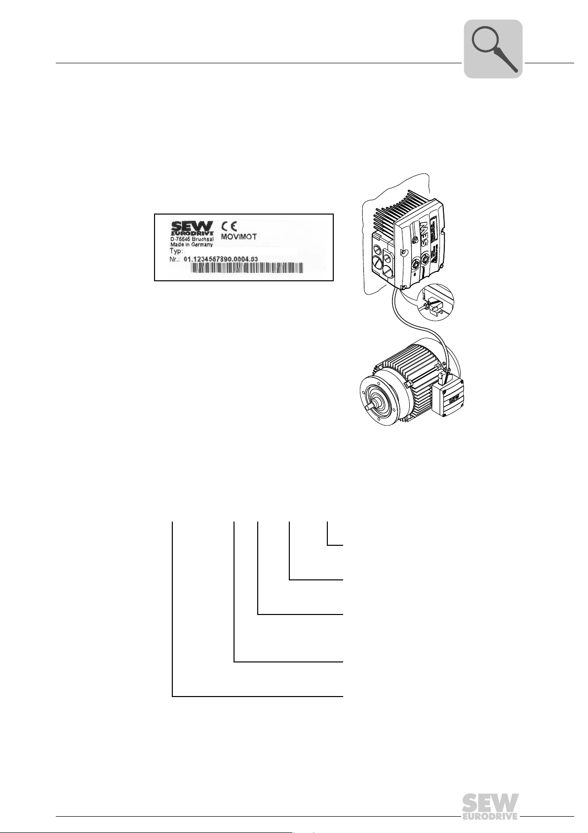
3.5 Type designation of the variant "mounted close to the motor"
3.5.1 Nameplate
The following illustration shows an example of the MOVIMOT
to the motor with corresponding nameplate:
MM15D-503-00/0/P21A/RO1A/APG4
®
3
inverter mounted close
3.5.2 Type designation
The following table shows the type designation of a MOVIMOT
to the motor:
MM15D-503-00/0/P21A/RO1A/APG4
457921547
®
inverter mounted close
Plug connector
For the connection to the motor
Connection box design
Adapter for mounting close to the motor
21 = Size 1
22 = Size 2
Connection type
0 =
1 =
MOVIMOT® inverter
Operating Instructions – MOVIMOT® MM..D with DRS/DRE/DRP AC Motor
17

4
Mechanical Installation
MOVIMOT® gearmotor installation
4 Mechanical Installation
4.1 MOVIMOT® gearmotor installation
4.1.1 General information
• Observe the general safety notes.
• Strictly observe all instructions as to the technical data and the permissible conditions regarding the place of installation.
• Only use the provided attachment options when mounting the MOVIMOT
• Only use mounting and locking elements that fit into the existing bores, threads and
countersinks.
4.1.2 Installation requirements
Make sure that the following requirements are met before you start installing the unit:
• The data on the nameplate of the drive matches the voltage supply system.
• The drive is undamaged (no damage caused by transportation or storage)
• The ambient temperature corresponds to the specifications in chapter "Technical
Data". Note that the temperature range of the gear unit may also be restricted (see
gear unit operating instructions).
• The MOVIMOT
ditions:
®
drive.
®
drive must not be installed under the following harmful ambient con-
Installation tolerances
– Potentially explosive atmospheres
– Oils
–Acids
– Gases
– Vapors
– Radiation
–etc.
• When the drive is installed in abrasive ambient conditions, protect the output end oil
seals against wear.
The following tables shows the permitted tolerances of the shaft ends and flanges of the
MOVIMOT
Shaft end Flanges
Diameter tolerance according to EN 50347
• ISO j6 with Ø ≤ 26 mm
• ISO k6 with Ø ≤ 38 mm up to ≤ 48 mm
• ISO m6 at Ø > 55 mm
• Center bore in accordance with DIN 332,
®
drive.
shape DR..
Centering shoulder tolerance in accordance
with EN 50347
• ISO j6 with Ø ≤ 250 mm
• ISO h6 with Ø > 300 mm
18
Operating Instructions – MOVIMOT® MM..D with DRS/DRE/DRP AC Motor

Mechanical Installation
MOVIMOT® gearmotor installation
4
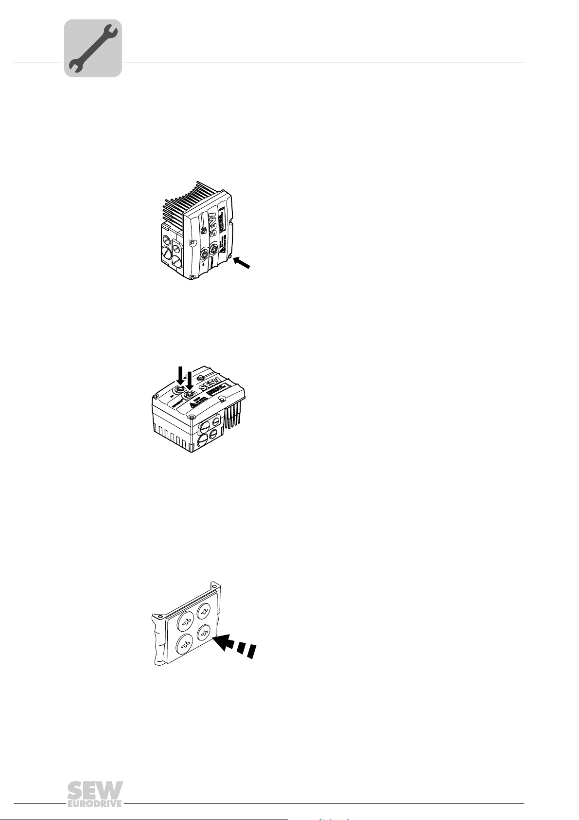
4.1.3 Installing MOVIMOT
NOTICE
Loss of warranted degree of protection if the MOVIMOT® inverter is installed incorrectly or not at all.
Damage to the MOVIMOT
• If you remove the MOVIMOT
it from moisture and dust.
Observe the following notes for mounting the MOVIMOT® drive:
• Only install the MOVIMOT
port structure.
• Observe the mounting position specified on the motor nameplate.
• Thoroughly remove any anti-corrosion agent from the shaft end. Use a commercially
available solvent. Do not allow the solvent to penetrate the bearings and shaft seals
– this could damage the material.
• Align the motor carefully to avoid placing any unacceptable strain on the motor
shafts. Observe the permitted overhung and axial loads specified in the "MOVIMOT
Gearmotors" catalog.
• Do not jolt or hammer the shaft end.
• Use an appropriate cover to prevent objects or fluids from entering motors in vertical
mounting positions.
®
®
inverter.
®
inverter from the connection box, you must protect
®
drive on a level, low-vibration, and torsionally rigid sup-
®
• Ensure sufficient clearance around the unit to allow for adequate cooling. Avoid the
drawing in of warm outlet air of other units.
• Balance components that were subsequent mounted to the shaft with a half key (output shafts are balanced with a half key).
• Existing condensation drain holes are sealed with plastic plugs.
Only open them, if necessary.
Open condensation drain holes are not permitted. If condensation drain holes are
open, higher enclosures are no longer possible.
4.1.4 Installation in damp locations or in the open
Observe the following notes for mounting the MOVIMOT
open:
• Use suitable cable glands for the cables. Use reducing adapters, if necessary.
• Coat the threads of the cable glands and filler plugs with sealing compound and
tighten them properly. Then coat the cable glands again.
• Seal the cable entries properly.
• Clean the sealing faces of the MOVIMOT
• If the corrosion protection coating is damaged, restore the coating.
• Check whether the degree of protection specified on the nameplate is permitted in
the ambient conditions on site.
®
drive in damp areas or in the
®
inverter well before re-assembly.
Operating Instructions – MOVIMOT® MM..D with DRS/DRE/DRP AC Motor
19
4
Mechanical Installation
Installation of MOVIMOT® options
4.2 Installation of MOVIMOT® options
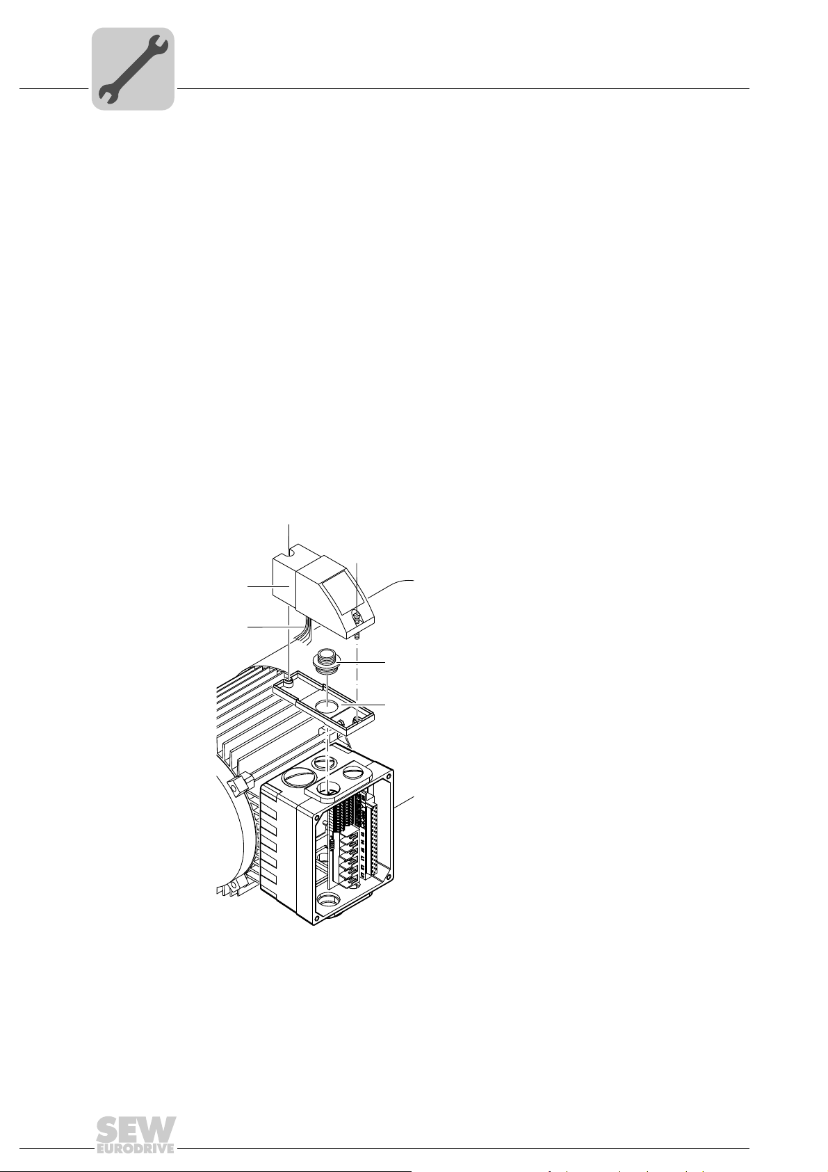
4.2.1 MLU11A / MLU21A / MLG..A option
Scope of delivery • MLU11A / MLU21A / MLG..A upper part [2]
• 2 screws [1]
• Transit bolt [4]
• MLU11A / MLU21A / MLG..A lower part [5]
Installation 1. Remove a screw plug on the MOVIMOT
2. Fix the lower part [5] on the MOVIMOT
bolt [4] (tightening torque 2.5 Nm / 22 lb.in).
3. Route the connection cable [3] through the transit bolt [4] into the inside of the
MOVIMOT
®
connection box.
4. Fit the upper part [2] onto the lower part [5] and fasten it with two screws [1] (tightening torque 0.9 – 1.1 Nm / 8 – 10 lb.in).
Mount the option in the following position only:
[1]
[1]
[2]
[3]
[4]
[5]
®
connection box.
®
connection box and fasten it with a transit
20
458285835
For more information about connecting the MLU11A/MLU21A option, refer to sec. "Connection of option MLU11A/MLU21A" (page 42).
For more information about connecting the MLG..A option, refer to sec. "Connection of
option MLG..A" (page 43).
Operating Instructions – MOVIMOT® MM..D with DRS/DRE/DRP AC Motor
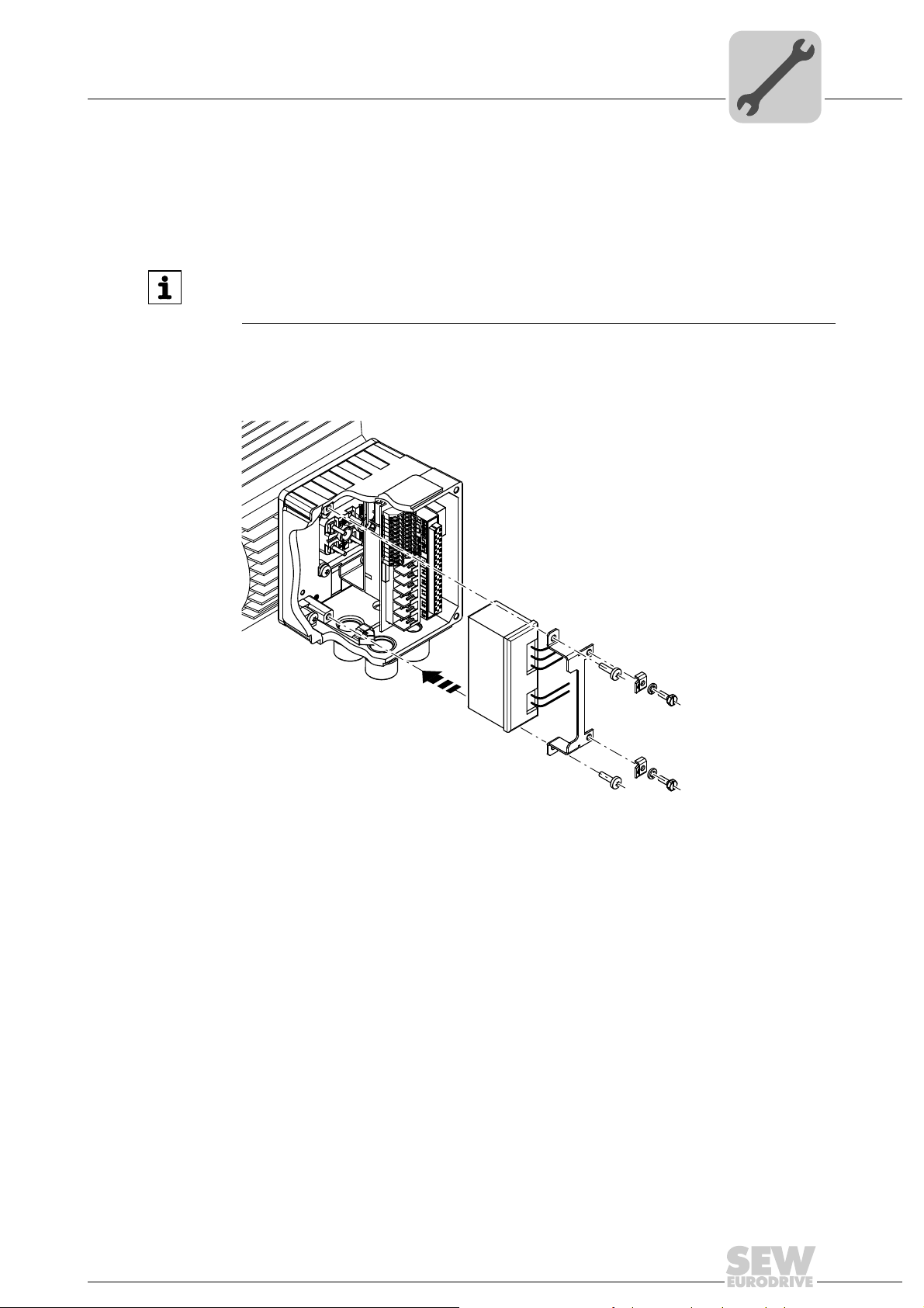
4.2.2 MLU13A option
Option MLU13A is installed in the modular connection box at the factory. If you have any
questions about retrofitting the option, please contact the SEW-EURODRIVE service.
The following figure depicts an installation example. The installation depends on the
used connection box and on other installed options, if there are any.
Mechanical Installation
Installation of MOVIMOT® options
INFORMATION
Only install this option in combination with the modular connection box of MOVIMOT
MM03D-503-00 – MM40D-503-00.
4
®
1113300875
For more information about connecting the MLU13A option, refer to chapter "Connection
of option MLU13A" (page 42).
Operating Instructions – MOVIMOT® MM..D with DRS/DRE/DRP AC Motor
21
4
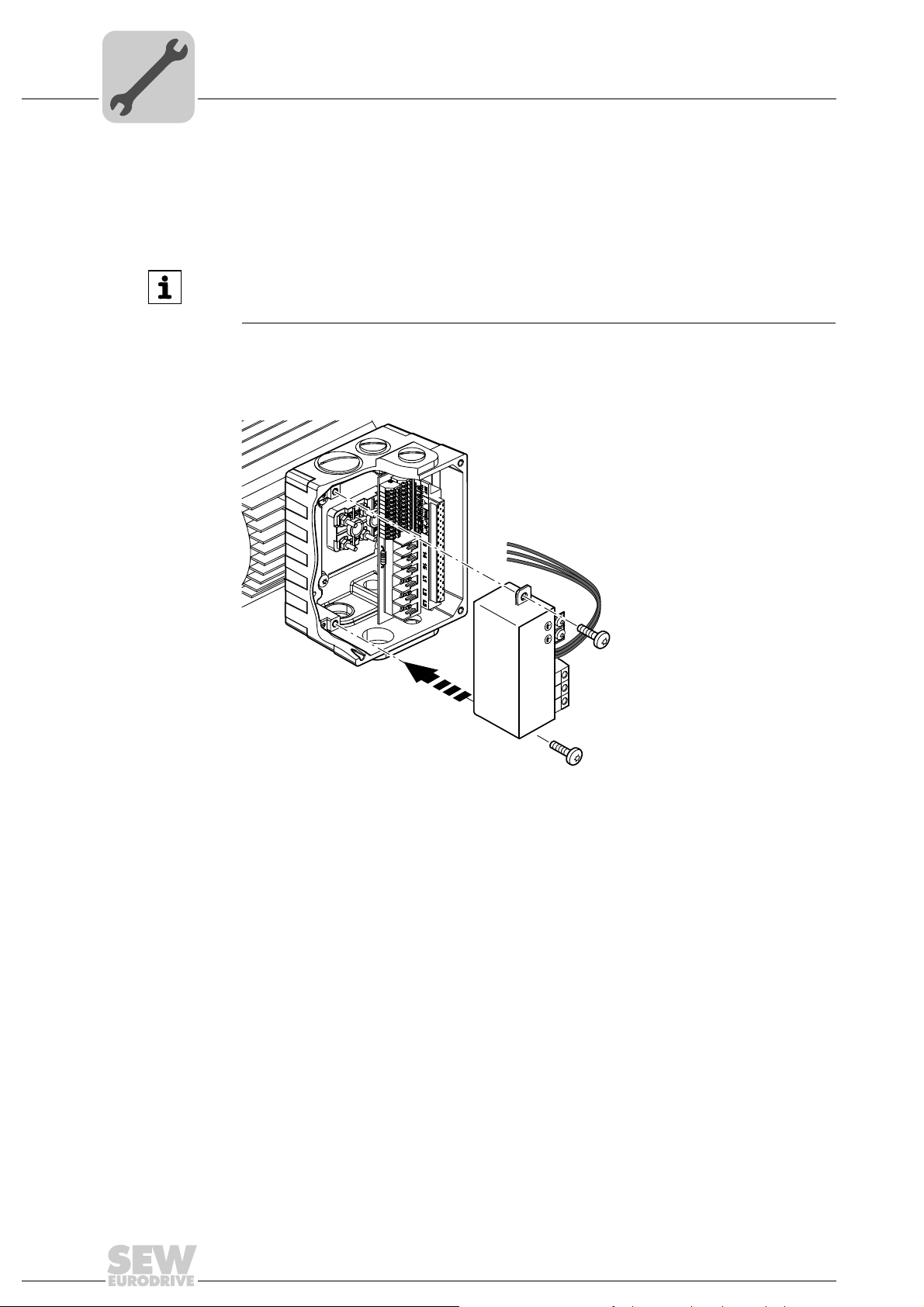
4.2.3 MNF21A option
Mechanical Installation
Installation of MOVIMOT® options
Option MNF21A is installed in the modular connection box at the factory. If you have any
questions about retrofitting the option, please contact the SEW-EURODRIVE service.
INFORMATION
Only install this option in combination with the modular connection box of MOVIMOT
MM03D-503-00 – MM15D-503-00.
The following figure depicts an installation example. The installation depends on the
used connection box and on other installed options, if there are any.
®
2753184651
For more information about connecting the MNF21A option, refer to chapter "Connecting the MNF21A option" (page 44).
22
Operating Instructions – MOVIMOT® MM..D with DRS/DRE/DRP AC Motor
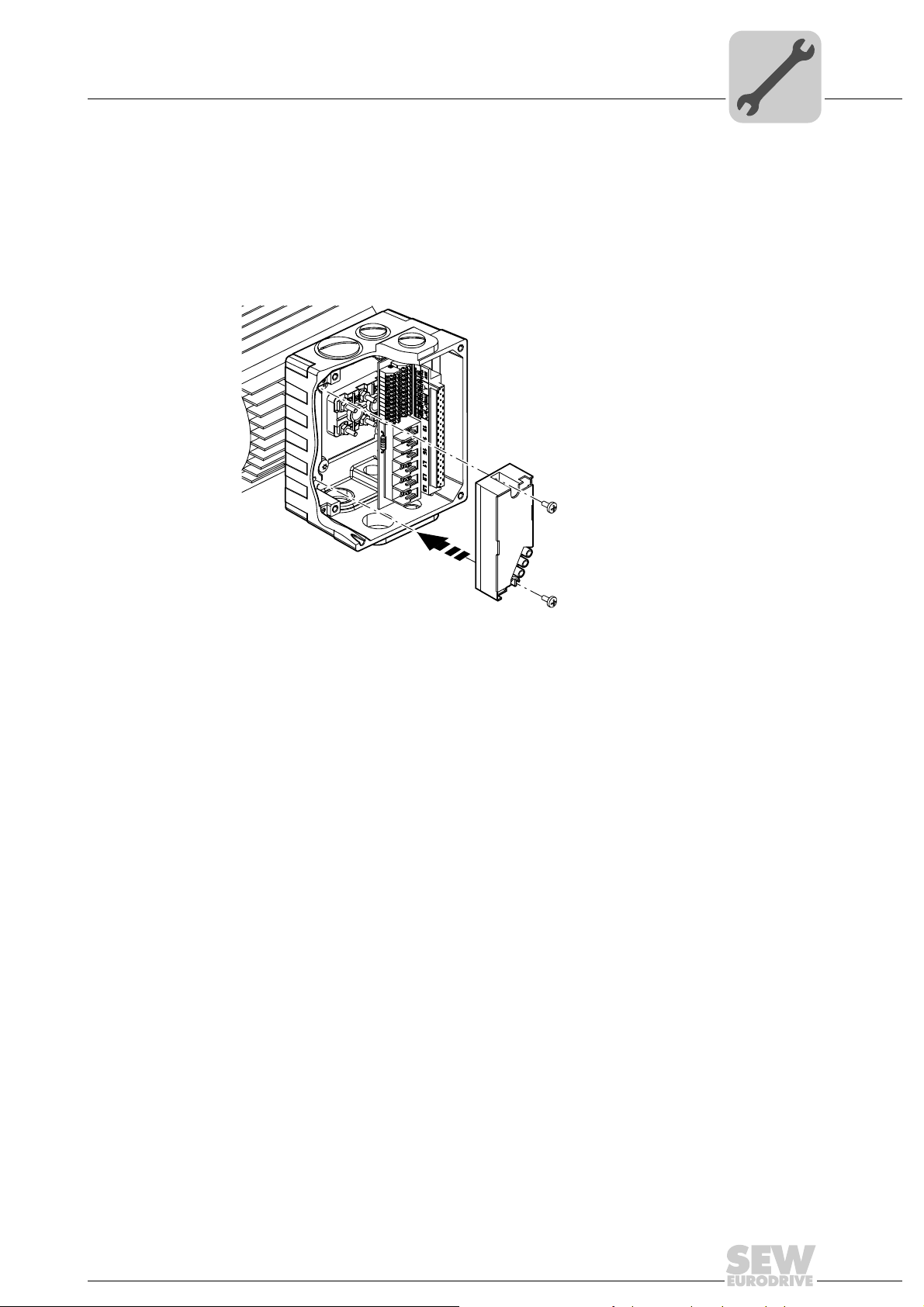
4.2.4 URM/BEM/BES options
The URM, BEM and BES options are installed in the connection box at the factory. If you
have any questions about retrofitting the options URM, BEM, or BES, please contact the
SEW-EURODRIVE service.
The following figure depicts an installation example. The installation depends on the
used connection box and on other installed options, if there are any.
Mechanical Installation
Installation of MOVIMOT® options
4
458307467
For more information about connecting the URM option, refer to chapter "Connection of
option URM" (page 45).
For more information about connecting the BEM option, refer to chapter "Connection of
option BEM" (page 46).
For more information about connecting the BES option, refer to chapter "Connection of
option BES" (page 47).
Operating Instructions – MOVIMOT® MM..D with DRS/DRE/DRP AC Motor
23
4
AB
2
M4
8
m
m
68 mm
56 mm
Ø 4,3 mm
M4
[1] M4 x 5 + a
M4 x 25
60
m
m
88
m
m
A
A
A
A
B
B
[3]
[2]
[4]
[5]
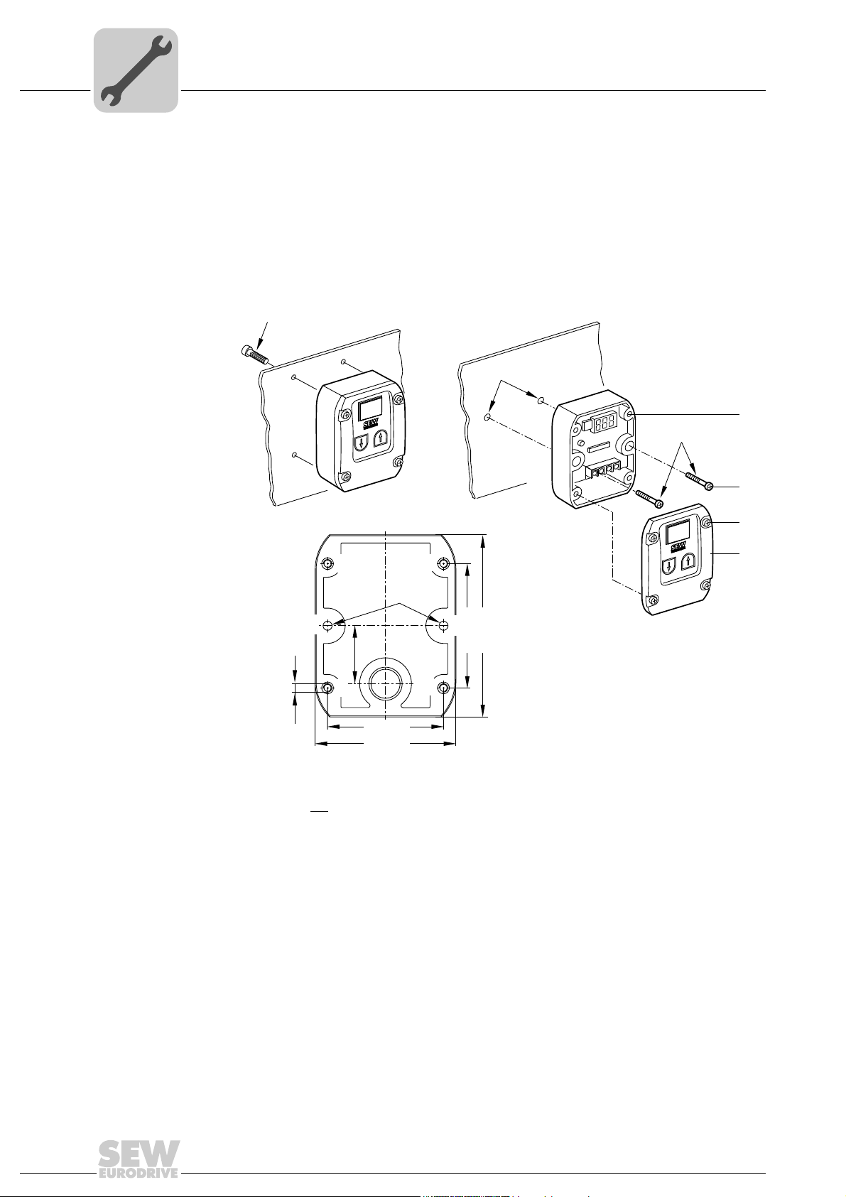
4.2.5 Installation MBG11A
Mechanical Installation
Installation of MOVIMOT® options
There are two ways to mount option MBG11A to a wall:
A: Mounting from the rear using 4 tapped holes.
(Tightening torque of retaining screw [1]: 1.6 – 2.0 Nm / 14 – 18 lb.in)
B: Mounting from the front using 2 retaining holes
(Tightening torque of retaining screw [3]: 1.6 – 2.0 Nm / 14 – 18 lb.in)
24
a = Wall thickness
Screws are not
Fit the upper part [5] onto the lower part [2] and fasten it with two screws [4] (tightening
torque 0.3 Nm / 2.6 lb.in).
For more information about connecting the MBG11A option, refer to sec. "Connection of
option MBG11A" (page 48).
included in the scope of delivery.
Operating Instructions – MOVIMOT® MM..D with DRS/DRE/DRP AC Motor
322404747
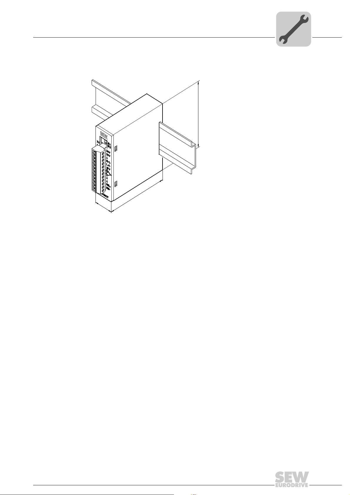
4.2.6 MWA21A option
22,5
74
75
Install option MWA21A in the control cabinet on a mounting rail according to EN 50022:
Mechanical Installation
Installation of MOVIMOT® options
4
322411915
For more information about connecting the MWA21A option, refer to sec. "Connection
of option MWA21A" (page 49).
Operating Instructions – MOVIMOT® MM..D with DRS/DRE/DRP AC Motor
25
4
rpm%
n11 n12
n13
f/A
RS485
COM
f
c max
IU
MWF11A
MWF11A
n11
n12
n13
X1
X3
X2
X4
X5
X4
rpm%
n13
f/A
RS485
COM
f
c ma
x
I
X4
100
75
52
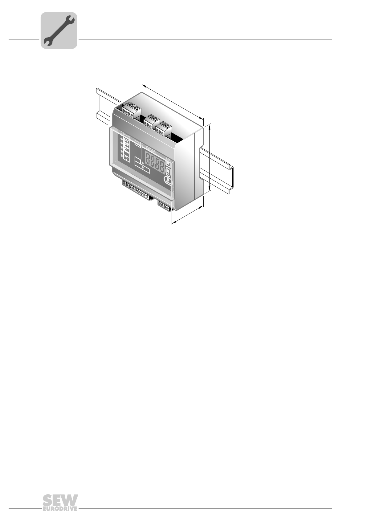
4.2.7 MWF11A option
Mechanical Installation
Installation of MOVIMOT® options
Install option MWF11A in the control cabinet on a mounting rail according to EN 50022:
3180221579
For more information about connecting the MWF11A option, refer to chapter "Connection of option MWF11A" (page 50).
26
Operating Instructions – MOVIMOT® MM..D with DRS/DRE/DRP AC Motor
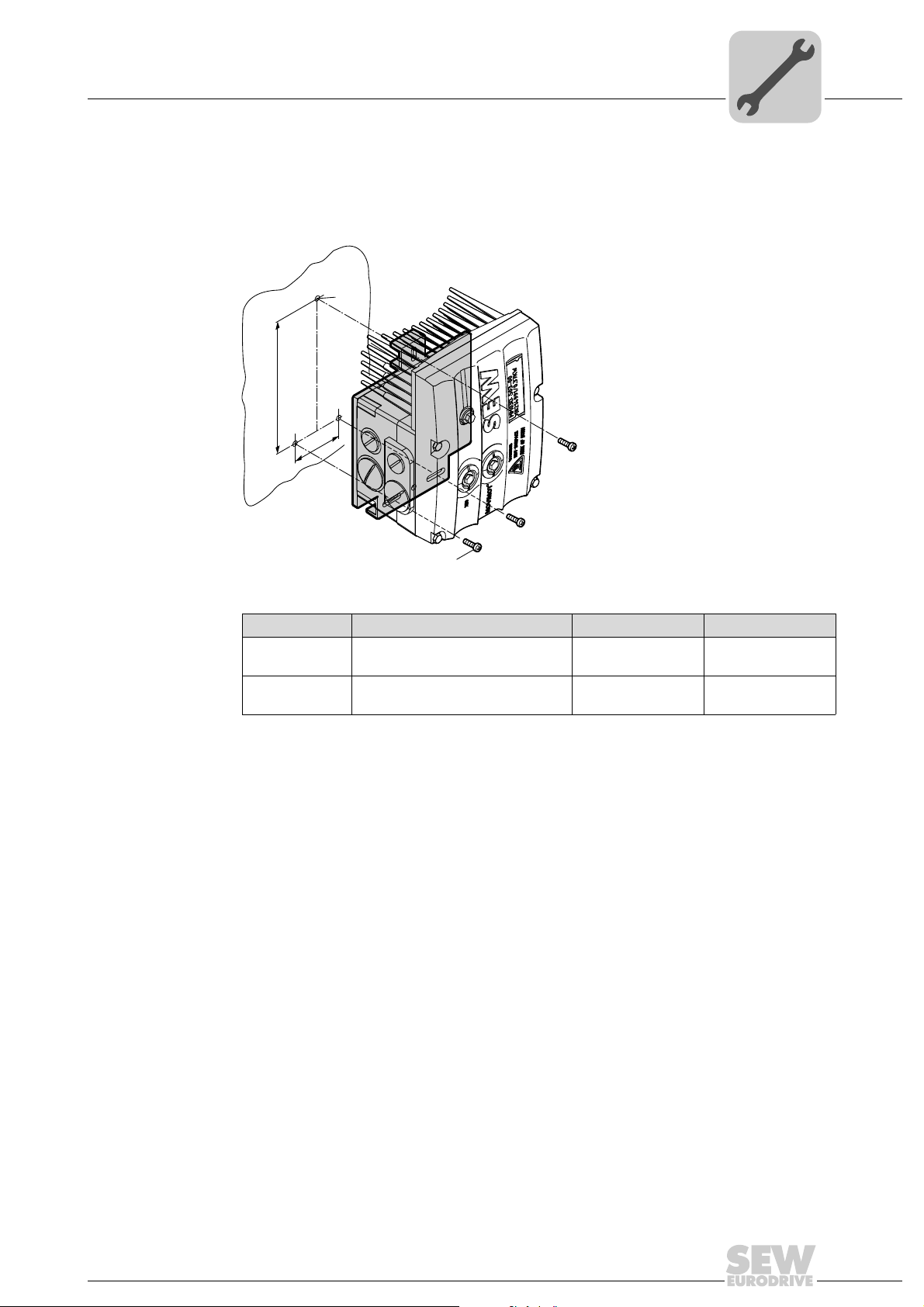
Mechanical Installation
Installation of the MOVIMOT® inverter close to the motor
4.3 Installation of the MOVIMOT® inverter close to the motor
The following figure shows the mounting dimensions for installing the MOVIMOT® inverter close to the motor:
M6
A
B
4
M6
Size Type A B
1
2 / 2L
MM03D503-00 – MM15D-503-00
MM03D233-00 – MM07D-233-00
MM22D503-00 – MM40D-503-00
MM11D233-00 – MM22D-233-00
140 mm 65 mm
170 mm 65 mm
458277771
Operating Instructions – MOVIMOT® MM..D with DRS/DRE/DRP AC Motor
27
4
Mechanical Installation
Tightening torques
4.4 Tightening torques
4.4.1 MOVIMOT® inverter
Tighten the screws on the MOVIMOT
nally across.
®
inverter using 3.0 Nm (27 lb.in) working diago-
458577931
4.4.2 Screw plugs
Tighten screw plugs of potentiometer f1 and connection X50 using 2.5 Nm (22 lb.in).
4.4.3 Cable glands
It is essential to observe the manufacturer's specifications for the cable glands.
4.4.4 Blanking plug cable entries
Tighten blanking plug screws with 2.5 Nm (22 lb.in).
458570379
28
322777611
Operating Instructions – MOVIMOT® MM..D with DRS/DRE/DRP AC Motor
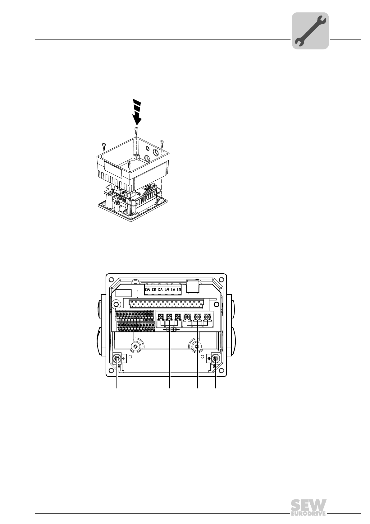
4.4.5 Modular connection box
[3][3] [1] [2]
For fastening the connection box on the mounting plate, tighten screws using 3.3 Nm
(29 lb.in).
Mechanical Installation
Tightening torques
4
4.4.6 Tightening torques for terminals
Use the following tightening torques for terminals during installation:
322786187
458605067
[1] 0.8 – 1.5 Nm (7 – 13 lb.in)
[2] 1.2 – 1.6 Nm (11 – 14 lb.in)
[3] 2.0 – 2.4 Nm (18 – 21 lb.in)
Operating Instructions – MOVIMOT® MM..D with DRS/DRE/DRP AC Motor
29
5
Electrical Installation
Installation instructions
5 Electrical Installation
5.1 Installation instructions
5.1.1 Supply system connection
• The rated voltage and frequency of the MOVIMOT
data for the power supply system.
• Install line fuses at the beginning of the power supply cable behind the supply bus
junction, see F11/F12/F13 in chapter "Connection of MOVIMOT
Use only D, D0 or NH fuses, or circuit breakers for F11/F12/F13. Select the fuse size
according to the cable cross section.
• SEW-EURODRIVE recommends using earth-leakage monitors with pulse code
measuring in voltage supply systems with a non-grounded star point (IT systems).
The use of such devices prevents the earth-leakage monitor mis-tripping due to the
earth capacitance of the inverter.
• Cable cross section: according to input current I
"Technical Data").
®
inverter must correspond to the
®
drive".
for rated power (see chapter
mains
®
5.1.2 Permitted cable cross section of MOVIMOT
terminals
Power terminals Observe the permitted cable cross sections for installation:
Power terminals
2
Cable cross section 1.0 mm
AWG17 – AWG12 (2 x AWG12)
Conductor end sleeves • For single assignment:
Only connect single-wire conductors or flexible conductors with conductor end sleeve (DIN 46228, material ECU) with or without insulating shrouds
• For double assignment:
Only connect flexible conductors with conductor end
sleeve (DIN 46228-1, material E-CU) without insulating shrouds
• Permitted length of the conductor end sleeve: At least 8
mm
- 4.0 mm2 (2 x 4.0 mm2)
Control terminals Observe the permitted cable cross sections for installation:
Control terminals
Cable cross section
• Single-wire conductor
(bare wire)
• Flexible conductor
(bare litz wire)
• Conductor with end sleeve
Without
• Conductor with end sleeve
With
Conductor end sleeves • Only connect single-wire conductors or flexible conduc-
insulating shrouds
insulating shrouds
tors with or without
material E-CU)
• Permitted length of the conductor end sleeve: At least 8
mm
0.5 mm
AWG20 – AWG17
0.5 mm2 – 0.75 mm
AWG20 – AWG19
conductor end sleeve (DIN 46228,
2
– 1.0 mm
2
2
30
Operating Instructions – MOVIMOT® MM..D with DRS/DRE/DRP AC Motor
 Loading...