

Page 1
Application
T200 Series
T200 series thermostats provide temperatur e control
on a variety of heating, cooling and single stage heat
pump applications.
The large LCD window displays room temperature
including degree increments indicated by a series of
dashes. The system heat output cycles on a 1 or 2F
degree field selectable differential. The cool output
differential is fixed at 2F degrees. The setpoint is
displayed and changed by pressing one of the setpoin t
buttons up or down. Installation is simplified by having
all of the field wires mounted to the separate wall pla te.
This is a powered thermostat, which must receive
75 mA of power at all times.
T200 Series
Digital, On/Off Thermostat
General Instructions
Features
• LCD window display
• Jumper selectable 5 minute time delay for heating
an
d cooling applications
• Mechanical contact for 40
(optional)
°
F limit freeze protection
Printed in U.S.A. 5/10 © Copyright 2010 Schneider Electric All Rights Reserved. F-27027-5
Page 2

SPECIFICATIONS
Inputs
Outputs
Environment
Table-1 Model Chart.
Power Input: 20 to 32 Vac, 75 mA to 1.2 amps.
Electrical:
Battery, Setpoint backup (Energizer 357 or equivalent).
Mechanical:
Operating Differential, Heati ng 1 or 2F degrees (0.6 or 1.1C degrees), Cooling 2F
degrees (1.1C degrees).
Setpoint Adjustment Range, 50 to 86° F (10 to 30°C). Material, Rigid vinyl. Finish, Off-white.
Temperature limits:
Shipping & Storage, -40 to 125°F (-40 to 52°C).
Operating, 40 to 125°F (5 to 53°C). Humidity: 95% non-condensing. Shipping Weight: 0.4 lbs (170 g). Location: NEMA Type 1.
Model Control Outputs
T201 Heating Only None Heat/Off None No No
T201-FP
T205-FP
T207-FP
a On T20X-FP (freeze protection) models a relay will provide power to a valve or relay if the thermostat fails.
a
T204 Cooling Only On/Auto Cool/Off None No No
T205 Cooling & Heating On/Auto Cool/Off/Heat Manual No No
a
T207 Cooling & Heating On/Auto Cool/Off/Heat Manual No Yes
a
Heating Only None Heat/Off None Yes No
Cooling & Heating On/Auto Cool/Off/Heat Manual Yes No
Cooling & Heating On/Auto Cool/Off/Heat Manual Yes Yes
Fan
Control
System
Switch
Changeover Mechanical Contact
B & O
Terminals
2 © Copyright 2010 Schneider Electric All Rights Reserved. F-27027-5
Page 3
TYPICAL APPLICATION (wiring diagram)
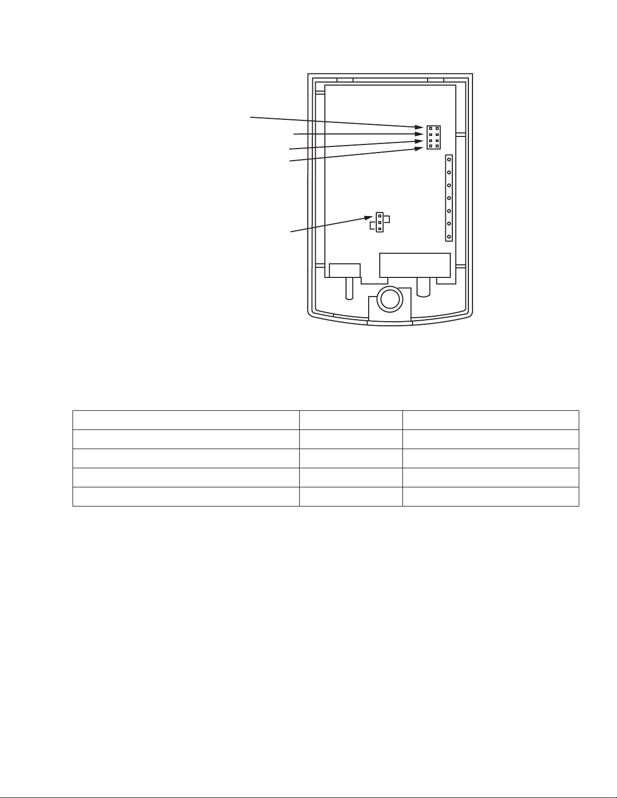
Figure-1 Terminal Identification.
DISPLAY
HEATING OPERATING
DIFFERENTIAL
HEAT CONTROL
COOL CONTROL
AUTO
FAN
CONTROL
HC
TH
RH
RC
W
Y
G
B
O
Table-2 Field Selectable Jumper Options.
Feature Jumpered Not Jumpered
1. Display Celsius Fahrenheit
2. Heating operation differential 2 degrees 1 degree
3. Heat control No delay 5 minute delay
4. Cool control* No delay 5 minute delay
* T201, heat only model, only has jumper options 1 thru 3. A fourth jumper location exists but is non-functional in heat only models.
F-27027-5 © Copyright 2010 Schneider Electric All Rights Reserved. 3
Page 4

RH
Figure-2 T201 Typical Wiring to Heating System With Single Transformer.
24 V AC
TRANSFORMER
24 V AC
120 V AC
FAN
RELAY
COOLING
RELAY
RC
Y
G
Optional 250 Ohm 5 watt resistor is needed
only if power drops below 75 milliamps.
1
1
1
Figure-3 Typical T204 Wiring to Cooling System With Single Transformer.
Figure-4 Typical T205 Wiring to Heating/Cooling System With Single Transformer.
W
24 VAC
1
HEATING
RELAY
24 VAC
TRANSFORMER
120 VAC
1
Optional 250W 5 watt resistor is needed
only if power drops below 75 milliamps.
FACTORY
INSTALLED
JUMPER
RH
RC
W
G
24 VAC HEATING
1
TRANSFORMER
24 VAC
Y
HEATING
RELAY
COOLING
RELAY
FAN
RELAY
120 VAC
1
If one of the secondary sides
of both transformers are grounded,
grounded sides must be connected
together.
4 © Copyright 2010 Schneider Electric All Rights Reserved. F-27027-5
Page 5

24 VAC HEATING
TRANSFORMER
24 VAC
120 VAC
24 VAC COOLING
TRANSFORMER
120 VAC
FAN
RELAY
COOLING
RELAY
RC
RH
Y
W
G
HEATING
RELAY
1
11If one of the secondary sides
of both transformers are grounded,
grounded sides must be connected
together.
FAC TORY
INSTALLED
JUMPER
Figure-5 Typical T205 Wiring to Heating/Cooling System With Dual Transformer.
24 VAC HEATING
TRANSFORMER
24 VAC
120 VAC
FAN
RELAY
COOLING
RELAY
RC
RH
Y
W
G
B
O
HEATING
RELAY
REVERSING
VALVE
1
1
Either the B or O output
will be connected to the
reversing valve. Terminal
O supplies 24V on a call
for cooling. Terminal B
supplies 24V on a call for
heat.
FACTORY
INSTALLED
JUMPER
Figure-6 Typical T207 Wiring To Heating/Cooling System With Single
Transformer & Reversing Valve.
INSTALLATION
Inspection
F-27027-5 © Copyright 2010 Schneider Electric All Rights Reserved. 5
Inspect the package for damage. If damaged, notify the appropriate carrier immediately.
If undamaged, open the package and inspect the device for obvious damage.
Return damaged products.
Requirements
• Tools (not provided)
— Writer’s Note: Need list.
• Training: Installer must be a qualified, experienced technician
• Other accessories as appropriate
Page 6

Precautions
]
W A R N I N G
]
C A U T I O N
N O T E
N O T E
]
W A R N I N G
General
• Electrical shock hazard! Disconnect power before installation to prevent electrical shock
or equipment damage.
• Make all connections in accordance with the electrical wiring diagram and in accordance
with national and local electrical codes.
• Avoid locations where excessive moisture, corrosive fumes, explosive vapors, or vibra-
tion are present.
• Avoid electrical noise interference. Do not install near large conductors, electrical
machinery, or welding equipment.
Federal Communications Commission (FCC)
This equipment has been tested and found to comply with the limits for a Class B digital
device, pursuant to Part 15 of the FCC Rules. These limits are designed to provide reasonable protection against harmful interference in residential installations. This equipment generates, uses, and can radiate radio frequency energy and may cause harmful interference if
not installed and used in accordance with the instructions. Even when instructions are followed, there is no guarantee that interference will not occur in a particular installation. If this
equipment causes harmful interference to radio and television reception—which can be
determined by turning the equipment off and on—the user is encouraged to try to correct the
interference by one or more of the following measures:
• Reorient or relocate the receiving antenna.
• Increase the separation between the equipment and receiver.
• Connect the equipment to an outlet on a circuit different from that to which the receiver
is connected.
• Consult the dealer or an experienced radio/television technician for help.
Canadian Department of Communications (DOC)
This class B digital apparatus meets all requirements of the Canadian Interference-Causing
Equipment Regulations.
Cet appareil numerique de la classe B respecte toutes les exigences du Reglement sur le
material broilleur du Canada.
European Standard EN 55022
This is a class B (European Classification) product. In a domestic environment this product
may cause radio interference in which case the user may be required to take adequate measures.
6 © Copyright 2010 Schneider Electric All Rights Reserved. F-27027-5
Page 7

Mounting
N O T E
Wiring
Mount the T200 series to a suitable surface. The T200 is shipped with an adapter plate
(4-1/4 x 4-3/4 in.) that covers the mounting blemishes of a previous thermostat. New
installation will not need the adapter plate. Do not mount on a surface that exceeds 125°F
(52°C).
• The T200 series is a powered thermostat which must receive 75 mA of power at all times.
• Some systems may require a 250 ohm, 5 watt resistor (included) to be installed across
the "W" and "C" terminals of the furnace or boiler control board (Figure-2) to assure
proper current draw for the thermostat. Install the resistor if the thermostat setpoint
cannot be adjusted, if the heating relay cycles too often (1-15 seconds), or if the heating
relay will not cycle.
• The T200 series cannot operate with a millivolt automatic self-powered gas heating
system unless an isolation relay and a separate 24 Vac transformer are used. Install an
isolation relay if the ignition blower runs continuously or if the furnace will not shut off
when the thermostat reaches the set temperature. Another symptom is that the furnace
may not turn on.
T201
The T201 models are a heat only model with a "HEAT/OFF" system switch and no fan
control. Applications include hydronic and radiant floor heating systems as well as gas and
electric forced air heating systems. Refer to Figure-2.
T204
The T204 model is a cool only model with a "COOL/OFF" system switch and a "FAN
ON/AUTO" fan switch. Applications include direct expansion cooling only systems. Refer to
Figure-3.
T205
The T205 models are heat/cool models with manual changeover. The unit consists of a
"COOL/OFF/HEAT" system switch and a "FAN/ON/AUTO" fan switch. Applications include
hydronic heating and radiant floor heating systems as well as gas and electric forced air
heating with conventional air conditioning systems. Refer to Figure-4 and Figure-5.
T207
The T207 models are heat/cool models with manual changeover and B (powered on heat
demand) and O (powered on cool demand) terminals. The unit consists of a
"COOL/OFF/HEAT" system switch and a "FAN ON/AUTO" fan switch. Applications include
all of the T205 applications plus single stage heat pumps and forced air zoning systems that
require B and O outputs. Refer to Figure-6.
For field selectable jumper options see Table-2.
For jumper and terminal locations see Figure-1.
Auto Fan Control (HC/TH)
A three-pin jumper (Figure-1) is set to enable the HC or TH mode.
The HC mode is used in electric heat applications to energize the fan relay at the same time
the heating relay is energized. The TH mode is used in fossil fuel applications where the
furnace, not the thermostat, controls the fan directly. In this application, a call for heat only
energizes the heating relay.
Optional Freeze Protection
When the T200 thermostat is ordered with the FP option a limit switch is wired in parallel with
the terminals R and W. This will provide power to a heating valve or relay if the thermostat
fails. This provides freeze protection to 40
source.
F-27027-5 © Copyright 2010 Schneider Electric All Rights Reserved. 7
°
F (4°C) as long as heat is available from the heat
Page 8

On October 1st, 2009, TAC be came the Buildings business of its parent com pany Schneider Electric. This document re flects the visual identity of Schneider Electric,
however there remains references to TAC as a corporate brand in the body copy. As each document is updated, the body copy will be changed to ref lec t ap propriate
CHECKOUT
7272
3-1/4
(81)
1-7/16
(36)
4-3/4
(121)
2-1/2
(64)
4-1/4
(108)
SYSTEM
SWITCH
FAN
SWITCH
Figure-7 T200 Series Dimensions.
MAINTENANCE
1. Verify jumper pin selections.
2. Verify that the T200 is wired correctly to your heating and or cooling loads.
3. Confirm that 75 milliamps are available at all times. To measure the current draw
connect an ammeter (set to measure milliamps) in series with the heat or cool output.
If power value is below 75 milliamps install a 250 ohm 5 watt resistor in parallel across
the switched load. Recheck for 75 milliamps. The T200 thermostats must have 75
milliamps to function properly.
4. Verify system Heat/Cool/Fan outputs:
Heating — Connect a voltmeter in parallel across the heat output terminal, W, and
common of the power source.
Cooling — Connect a voltmeter in parallel across the cooling output terminal, Y, and
common of the power source.
Fan — Connect a voltmeter in parallel across the fan terminal, G, and common of the
power source.
5. The display will show the current room temperature as a number. Up to five dashes will appear under the number. Each dash represents 1/5 of a degree. The thermostats ON/OFF switching is based on whole degrees.
The T200 series requires no maintenance. Replace defective modules.
Regular maintenance of the total system is recomended to assure sustained, optimum
performance.
FIELD REPAIR
DIMENSIONAL DATA
Replace battery with Energizer 357 or equivalent as needed. Replace any damaged or failed
components with functional replacements.
corporate brand changes.
Copyright 2010, Schneider Electric
All brand names, trademarks and registered
trademarks are the property of their respective
owners. Information contained within this
document is subject to change without notice.
F-27027-5
 Loading...