

Page 1

User Guide
PowerChute™ Network Shutdown v4.4.1
Standard
990-4595H-001
01/2021
Page 2

Schneider Electric Legal Disclaimer
The information presented in this manual is not warranted by Schneider Electric to be authoritative, error free,
or complete. This publication is not meant to be a substitute for a detailed operational and site specific
development plan. Therefore, Schneider Electric assumes no liability for damages, violations of codes,
improper installation, system failures, or any other problems that could arise based on the use of this
Publication.
The information contained in this Publication is provided as is and has been prepared solely for the purpose of
evaluating data center design and construction. This Publication has been compiled in good faith by Schneider
Electric. However, no representation is made or warranty given, either express or implied, as to the
completeness or accuracy of the information this Publication contains.
IN NO EVENT SHALL SCHNEIDER ELECTRIC, OR ANY PARENT, AFFILIATE OR SUBSIDIARY COMPANY
OF SCHNEIDER ELECTRIC OR THEIR RESPECTIVE OFFICERS, DIRECTORS, OR EMPLOYEES BE
LIABLE FOR ANY DIRECT, INDIRECT, CONSEQUENTIAL, PUNITIVE, SPECIAL, OR INCIDENTAL
DAMAGES (INCLUDING, WITHOUT LIMITATION, DAMAGES FOR LOSS OF BUSINESS, CONTRACT,
REVENUE, DATA, INFORMATION, OR BUSINESS INTERRUPTION) RESULTING FROM, ARISING OUT,
OR IN CONNECTION WITH THE USE OF, OR INABILITY TO USE THIS PUBLICATION OR THE CONTENT,
EVEN IF SCHNEIDER ELECTRIC HAS BEEN EXPRESSLY ADVISED OF THE POSSIBILITY OF SUCH
DAMAGES. SCHNEIDER ELECTRIC RESERVES THE RIGHT TO MAKE CHANGES OR UPDATES WITH
RESPECT TO OR IN THE CONTENT OF THE PUBLICATION OR THE FORMAT THEREOF AT ANY TIME
WITHOUT NOTICE.
Copyright, intellectual, and all other proprietary rights in the content (including but not limited to software, audio,
video, text, and photographs) rests with Schneider Electric or its licensors. All rights in the content not expressly
granted herein are reserved. No rights of any kind are licensed or assigned or shall otherwise pass to persons
accessing this information.
This Publication shall not be for resale in whole or in part.
Page 3

Table of Contents
Introduction ................................................................................................................................................................... 1
UPS Configuration ........................................................................................................................................................ 2
Network Configuration ............................................................................................................................................... 3
UPS Configuration Options ....................................................................................................................................... 4
Network Management Card Connection ................................................................................................................... 6
Advanced UPS Setups .............................................................................................................................................. 8
Outlet Group Registration ....................................................................................................................................... 10
Network Management Card Settings ...................................................................................................................... 11
Shutdown Settings ...................................................................................................................................................... 12
UPS Shutdown ........................................................................................................................................................ 13
Shutdown Command Files ...................................................................................................................................... 14
Shutdown Settings for Advanced UPS Configurations ........................................................................................... 15
SSH Settings ............................................................................................................................................................... 17
SNMP Configuration ................................................................................................................................................... 20
SNMPv1 Configuration ............................................................................................................................................ 21
SNMPv3 Configuration ............................................................................................................................................ 22
SNMP Trap Configuration ....................................................................................................................................... 23
SNMP Data Points .................................................................................................................................................. 25
Event Configuration .................................................................................................................................................... 32
Notifications ............................................................................................................................................................. 33
Event-Driven Command Files ................................................................................................................................. 34
Shutdown Actions ................................................................................................................................................... 35
Sequenced Server Shutdown ..................................................................................................................................... 36
Sample Shutdown Scenarios ...................................................................................................................................... 37
UPS without Outlet Groups ..................................................................................................................................... 38
UPS with Outlet Groups .......................................................................................................................................... 40
PowerChute Events and Logging ............................................................................................................................... 44
Configurable Events ................................................................................................................................................ 45
Configurable Environmental Events ........................................................................................................................ 49
Non-Configurable Events ........................................................................................................................................ 50
Configuration (INI) File Events ................................................................................................................................ 54
SSH Action Events .................................................................................................................................................. 56
Java Update Events ................................................................................................................................................ 57
Critical Events in a Redundant-UPS Configuration ................................................................................................. 58
Critical Events in a Parallel-UPS Configuration ...................................................................................................... 59
General ....................................................................................................................................................................... 60
Communications Settings ....................................................................................................................................... 61
i
Page 4

Table of Contents
PowerChute Agents ................................................................................................................................................ 62
PowerChute Configuration File ............................................................................................................................... 63
Java Update ............................................................................................................................................................ 64
User Interface Session Timeout .............................................................................................................................. 65
Check for Updates .................................................................................................................................................. 66
Customer Support ................................................................................................................................................... 67
Customer Experience Improvement Program (CEIP)............................................................................................... 68
Troubleshooting .......................................................................................................................................................... 69
Network
Browser Troubleshooting ........................................................................................................................................ 71
SSH Ac
SNMP Troubles
General Troubleshooting ......................................................................................................................................... 74
Management Card Troubleshooting ......................................................................................................... 70
tions Troubleshooting ................................................................................................................................. 72
hooting ........................................................................................................................................... 73
ii
Page 5

Introduction
After installation, it is essential to configure t he software using the PowerChute Setup wizard. This
ensures that PowerChute is aware of UPS critical events in order to protect
PowerChute
(NMC) to provide network-based s hutdown of multiple computer systems.
In the case of a UPS critical event, the software performs a graceful, unattended system shutdown before the UPS
battery is exhausted. The number of protected sy st ems is limited only by the capacity of the UPS.
View these Application Notes for detailed information on using PowerChute in specific environments.
TM
Network Shutdown (PowerChute) works in conjunction with the UPS Network Management Card
your system.
1
Page 6

UPS Configuration
This section contains information on the topics below:
• Network Configuration
• U
PS Configuration Options
• N
etwork Management Card Connection
• A
dvanced UPS Setups
• O
utlet Group Registration
etwork Management Card Settings
• N
2
Page 7

PowerChute Network Shutdown: Standard User Guide
Network Configuration
PowerChute can use IPv4 or IPv6 to communicate wi th the Network Management Card(s).
IPv6 support is available only for Network Management Card 2 firmware 6.0.X or higher, and Network
Management Card 3.
Select IP
If your computer has more than one IPv4 address you wil l need to select one of the available addresses. The IP
address you select will be registered with the NMC a nd di splayed in the NMC user interface under Configuration PowerChute Clients.
IPv6 Configuration
If you are using IPv6 to communicate with the NMC(s), each network adapter on your machine will typically have
several IP addresses assigned to it. Each adapter will have at least one link-local address and one global unicast
address assigned to it.
Use the Unicast IP Address drop-down box to specify which address to use. The address type selected in this
drop-down box must match the address type that you enter for the NMC(s) on the Network Management Card
Connection page. This unicast address will be re gi stered on the NMC(s) and displayed on the PowerChute
Network Shutdown Clients page of the NMC.
f
e80::88c8:3d95:bc02:74cc is an example of a li nk-local address.
2001:112:1:0:88c8:3d95:bc02:74cc is an example of a global unicast address.
Multicast Option
The NMC supports sending communication packets to an IPv6 Multicast address instead of sending unicast
packets to each PowerChute agent. To use this, enable the Multicast check box and enter an IPv6 Multicast
address.
The multicast address that is entered here will be re gi stered on the NMC(s) instead of the unicast address and
displayed on the PowerChute Network Shutdown Clients page of the NMC. The NMC(s) will send communication
packets to that multicast address.
FF0
2::1 is an example of a multicast address with link-l o cal scope so that only nodes on the same
physical network segment will receive it. I f using a link-local unicast address, you must use a multicast
address with link-local scope.
FF0E::1 is an example of a multicast address with global scope and the NMC will use its global unicast
address to send the packet. If using a global unicast address you must use a multicast address with global
scope.
For detailed information, please view "The Com m unications Process of PowerChute Network Shutdown" here.
3
Page 8
UPS Configuration
UPS Configuration Options
For a detailed overview of which UPS’s support each confi guration, please view the “PowerChute Network
Shutdown Operating Modes and supported UPS Conf i gurat i ons” Application Note here.
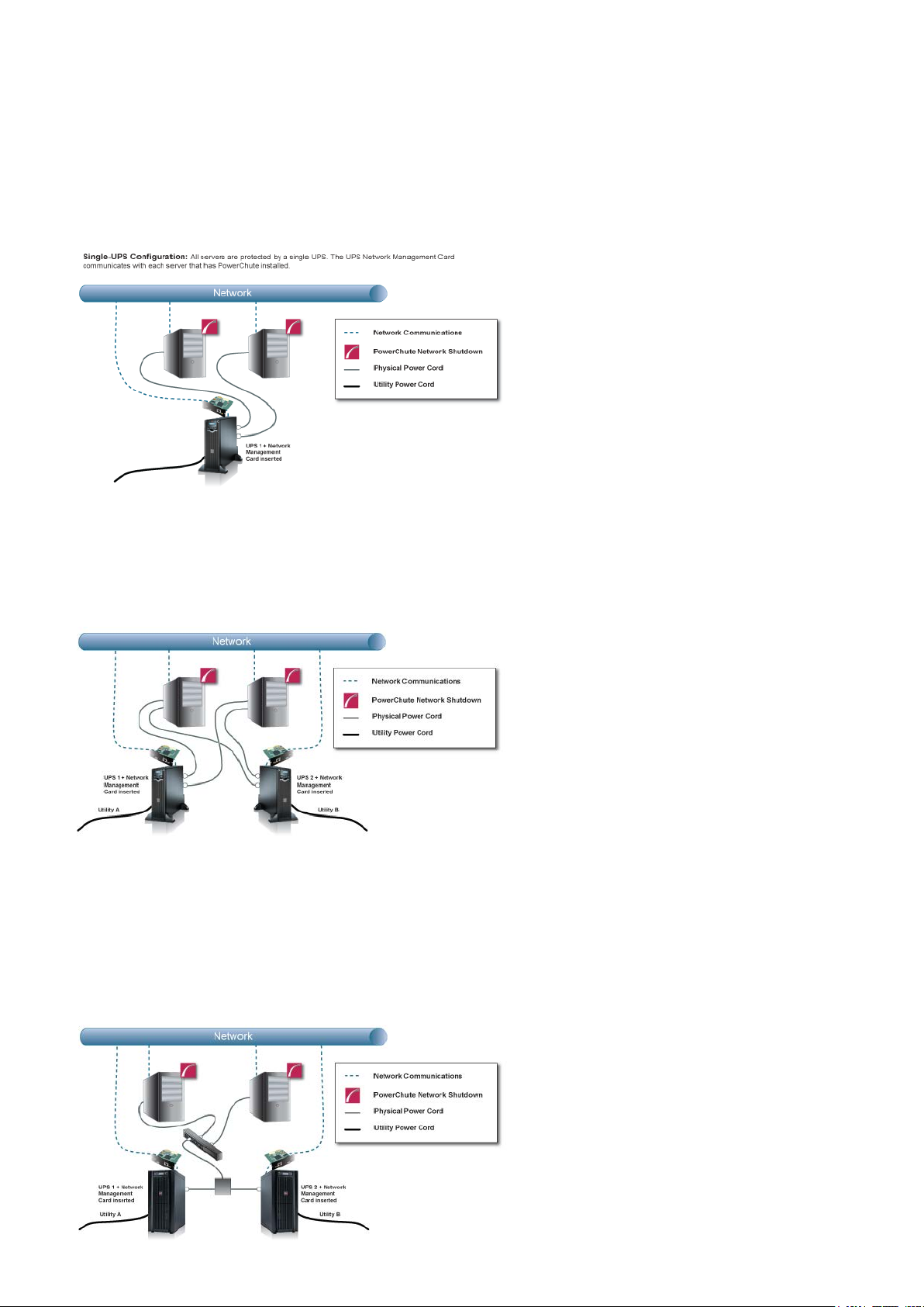
Single-UPS Configuration
Redundant-UPS Configuration
Redundant-UPS Configuration: Two or more UPS's of the same model protect each server. Each UPS
can support the server load on its own. All UPS Network Management Cards communicate with each
server that has PowerChute installed.
For detailed information, please view “Using PowerChute Network Shutdown in a Redundant-UPS
Configuration” Application Note here.
Parallel-UPS Configuration
Parallel-UPS Configuration: Two or more UPS's of the same model protect the load and provide redundancy or
increased capacity depending on the load. The UPS outputs are tied together so a single output goes to the load. All
UPS Network Management Cards communicate with each server that has PowerChute installed.
4
Page 9
PowerChute Network Shutdown: Standard User Guide
Note: To use the Parallel-UPS configuration, your UPS devices must already be configured to operate in parallel
mode.
For detailed information, please view “Using PowerChute Network Shutdown in a Parallel-UPS Configuration”
Application Note here.
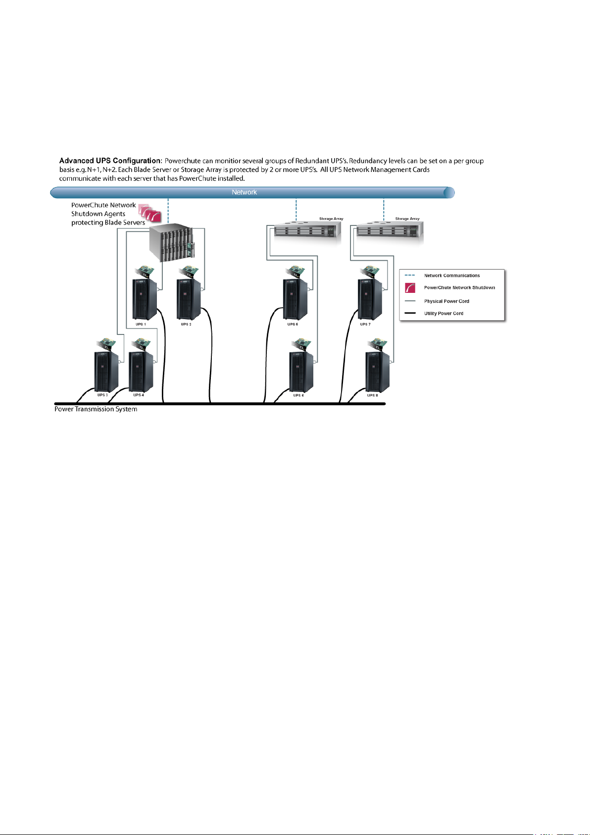
Advanced UPS Configuration
For detailed information, please view the “Using P owerChute Network Shutdown in an Advanced Redundant
Setup” Application Note here.
5
Page 10
UPS Configuration
The NMC uses a self
enable "Accept Untrusted SSL
the NMC if a self
Network Management Card Connection
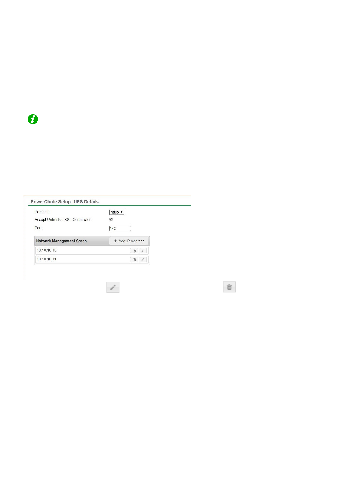
Network Management Card 2 firmware v6.8.0 and higher, and Network Management Card 3 firmware v1.1.0.16
and higher uses the HTTPS protocol by default. T he default protocol for PowerChute is HTTPS which can be
changed to HTTP, although it is not recommended.
The default port is 80 for HTTP, and 443 for HTTPS. Do not change this number unless you changed the port being
used by your NMC.
-signed SSL certificate by default when HTTP S is enabled. You need to
Certificates" to allow PowerChute to establish communication with
-signed certificate is being used by the NMC.
For Redundant and Parallel configurations, you need to enter more than one IP address to enable
communications with all the relevant NMCs.
For more information on UPS configurations and supported UPS models, view the Application Note "PowerChute
Network Shutdown Operating Modes and supported UPS Configurations" here.
Add each IP address using the + Add IP Address butt on. Enter the IP address of the NMC in the UPS. Click OK.
To edit an
IP address, click the icon. To delete an IP address, click the icon.
Adding a Trusted Certificate to PowerChute for NMC communication
When using the HTTPS protocol to communicate with the NMC, you must select the Accept Untrusted SSL
Certificates check box. However, it is possible to create a Trusted Certificate file and add it to the PowerChute
truststore.
Your NMC Security Handbook has details on the Security Wizard used to create the Trusted Certificate file with an
extension .CRT. This file is then used to create com ponents that can be uploaded to the NMC to replace the default
self-signed certificate.
In order to facilitate the trusted SSL communication of PowerChute with the NMC, this Trusted Certificate file must
then be added to the system Java cacerts keystore or to the PowerChutekeystore file. (You can do this using the
Java keytool.exe; for details see the Java help documentation). Adding it to the cacerts keystore means it is
available to all your applications as distinct from just PowerChute.
By default the PowerChute-keystore file is located in APC\PowerChute\group1. If you add the Trusted Certificate
and you subsequently get a connection error with the NMC, then it could be because a) the certificate has expired,
b) it is not yet valid, or c) it has been revoked. In any of these cases, you need to add a new Trusted Certificate to
the PowerChute server or to upload a new valid SSL certificate to the NMC.
6
Page 11

PowerChute Network Shutdown: Standard User Guide
For more information, see the PowerChute Network Shutdown Security Handbook.
The PowerChute-keystore file only exists after the f irst attempt is made to communicate with the
NMC using HTTPS (by using the configuration wizard for example). For this reason, for a silent
installation you must add the Trusted Certificate to the Java cacerts keystore.
PowerChute only checks the keystore when it s se rv i ce starts. After you add the Trusted
Certificate, you will need to re-start the PowerChute service if it ’s already running.
NMC PowerChute Support
In NMC 2 firmware v6.8.0 and higher and NMC 3 firmware v1.1.0.16 and higher, PowerChute support is disabled
by default. This may result in an error while PowerChute registers with the NMC(s). If an error is displayed, log in to
the NMC UI and ensure PowerChute support is enabled.
In the NMC Web UI, you must specify a user name and aut hentication phrase before PowerChute can be enabled.
You must also choose the protocol used to communicate with PowerChute (HTTP/HTTPS). NOTE: The chosen
protocol must be enabled on the NMC before PowerChute communications can be established. For more
information, refer to the NMC User Guide available on the APC website.
7
Page 12
UPS Configuration
Advanced UPS Setups
Add UPS Setup
In an Advanced UPS configuration, a single instan ce of PowerChute Network Shutdown can monitor multiple UPS
setups and initiate graceful shutdown of equipment based on different redundancy levels. Each setup can be a
single UPS or a UPS group. A single UPS setup is represented by the icon. A UPS group is represented by the
icon.
For example, one setup may be a group of UPS's that are conf i gured with N+2 redundancy. Another setup may be
a single UPS.
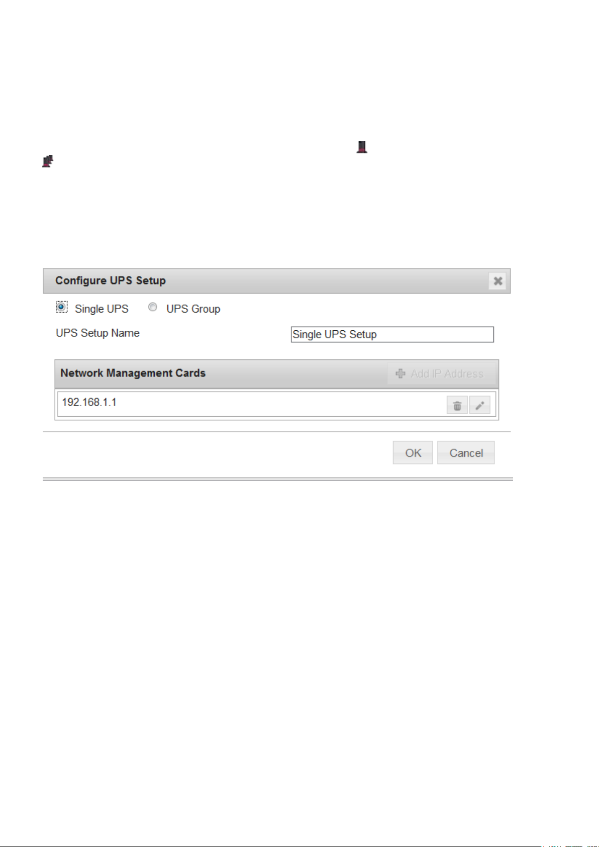
On the UPS Details page of the Setup Wizard, click the + Add UPS(s) button to create a new setup.
To create a setup with a single UPS, on the Configure UP S Setup dialog choose Single UPS:
1. Enter a UPS Setup Name (with a maximum of 20 ASCII characters)
2. Click the + Add IP Address button and enter the IP address of the Netw ork Management card in the UPS.
Click OK.
3. Click OK to complete Single UPS Setup.
8
Page 13
PowerChute Network Shutdown: Standard User Guide
PowerChute has been tested with a total of 16 NMC s in an advanced configurat
possible to configure for more than 16 NMCs in this conf iguration.
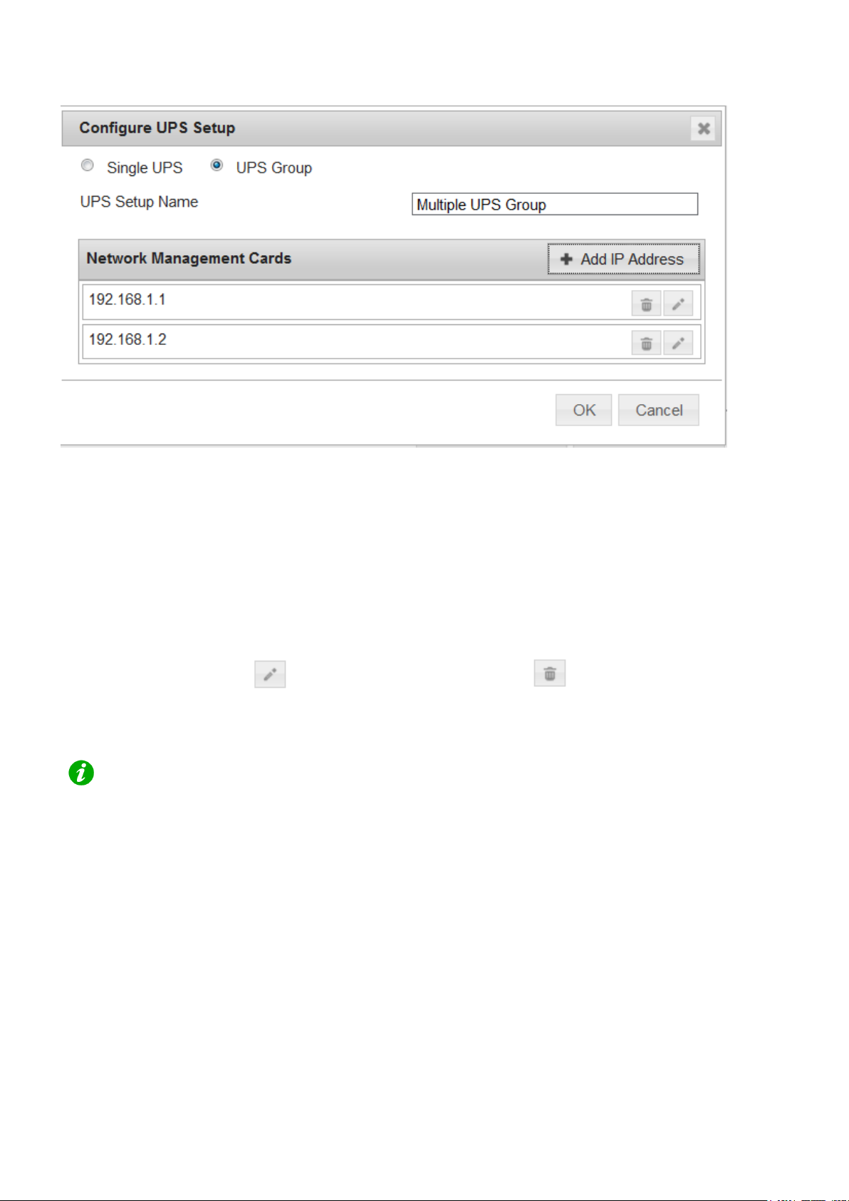
To create a setup with a group of UPS devices, choose UPS Group:
1. Enter a UPS Setup Name (with a maximum of 20 ASCII characters)
2. Click the + Add IP Address button and enter the IP address of the Netw ork Management card in the UPS.
Click OK.
3. Repeat for each of the UPS devices to be added to the UPS group. A minimum of 2 IP addresses is
required to set up a UPS Group.
4. Click OK to complete Group UPS Setup.
Repeat for each UPS setup required.
To edit a UPS Setup, click the icon. To delete a UPS setup, click the icon.
Click the Next button to go to the next step of the Setup Wizard.
ion. However it is
For detailed information, please view the “Using P owerChute Network Shutdown in an Advanced Redundant
Setup” Application Note here.
9
Page 14

UPS Configuration
Outlet Group Registration
If your UPS supports outlet groups you must specif y which one the server is being powered by so that PowerChute
can monitor it for shutdown events and also issue turn-off commands to that outlet group.
UPS Shutdown Behavior in Mixed UPS Environments
If your servers are being powered by a mix of outlet-aware UPS’s (e.g. SMX/ SMT) and non-outlet-aware UP S’ s
(e.g. SU/ SUA) in a Redundant UPS Configuration, P owerChute only provides the option to turn off the UPS and
not the outlet group.
Your servers are still protected if there is a UPS critical event or if the outlet group is commanded to shut down e.g.
via the NMC User Interface.
10
Page 15
PowerChute Network Shutdown: Standard User Guide
Network Management Card Settings
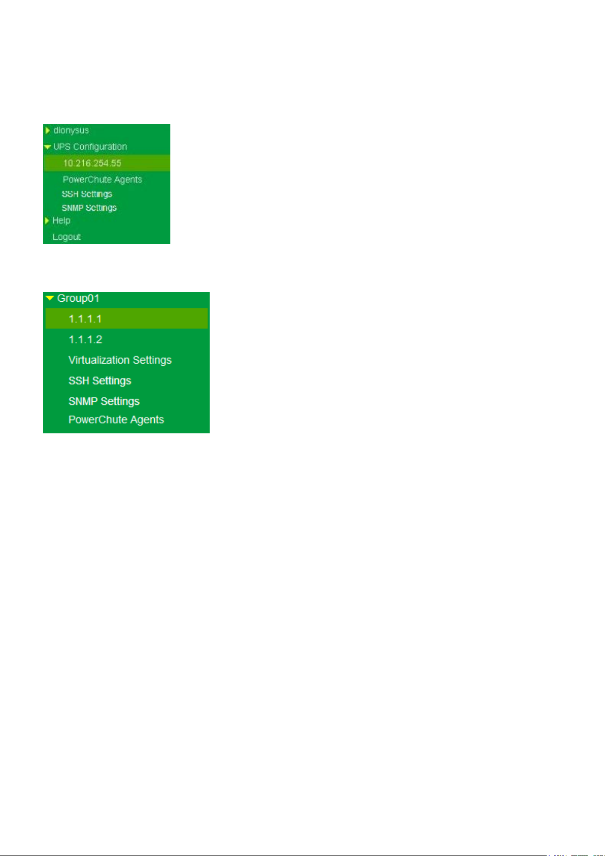
For Single, Redundant and Parallel UPS configurat i ons, the IP address of each NMC that PowerChute is
communicating with is displayed under the UPS Configuration menu option.
For Advanced UPS configuration, each UPS Setup is displayed as a menu item and the IP address of the NMC(s)
with which PowerChute is communicating is displayed under each UPS setup.
Click on the IP address to view the UPS information specific to that NMC.
UPS information displayed includes:
• NMC IP Address
• UPS model name
• UPS configuration
The NMC Host Name from the NMC's DNS settings page under Network - DNS - Configuration is also displayed.
This is not the same as the UPS name that can be set under Configuration - UPS General on the NMC.
Clicking the Launch button opens the NMC user interface.
11
Page 16

Shutdown Settings
The Shutdown Settings page enables you to config ure UPS turnoff and the shutdown command files.
• UPS Shutdown
• Shutdown Command Files
• Shutdown Settings for Advanced UPS Configurati ons
12
Page 17
PowerChute Network Shutdown: Standard User Guide
The default behavior for most UPS’s if they are turne d off following an on
they will turn on again once input power is restored.
The
Shutdown where you can change the behavior to Turn off and Stay off if required.
This is not available for an Advanced UPS Configuration that contains UPS Setups with
Redundant UPS devices.
If one UPS is on battery and anoth
Single UPS turn off has elapsed, then the first UPS will not be turned off.
UPS Shutdown
The default setting is Do not turn off the UPS.
You can select Turn off the UPS if you want to preserve battery power. Some U PS’s do not support UPS turnoff
through PowerChute or the NMC. For these models, i t can only be done at the UPS itself. Please check your UPS
documentation to ensure your model supports UPS turnoff.
If your UPS has Switched Outlet Groups, then t he Turn off the UPS Outlet Group option enables you to turn off
the outlet group that supplies power to the PowerChute protected server after a critical event occurs.
-battery shutdown is that
On-Battery Shutdown Behavior setting can be found in the NMC under Configuration –
Turn Off Single UPS On Battery in a Redundant-UPS Configuration
In a Redundant UPS configuration you have the option to turn off one of the UPS’s after it has switched to battery
power. This is designed to prolong the battery li fe and preserve the battery power of the UPS. If using this feature
on a UPS that supports outlet groups the option "Turn off the UPS" should be enabled.
The load is still protected by the other UPS in t he configuration.
After the specified delay, PowerChute will is sue a command to gracefully turn off the UPS.
er UPS switches to battery before the configur ed delay for
If the shutdown action is enabled for the On Battery event, a Multiple Critical event condition will
occur if a second UPS switches to battery power (aft er the first UPS has been commanded to
turn off by PowerChute). When this occurs the shutdown sequence will start after 10 seconds.
13
Page 18

Shutdown Settings
Shutdown Command Files
A Shutdown Command File can be configured to run if a UPS critical event is triggered.
Full path to command file: You must specify the full path name of the command file, including the disk drive
or volume name. For Linux and Unix systems, the file should execute permissions of chmod +x [command file
name].
The command file must be located in the user_files folder, or a sub-folder, in the PowerChute
installation directory. If the default installation directory was chosen during installation, this location will
be:
• C:\Program Files\APC\PowerChute\user_files for Windows systems
• /opt/APC/PowerChute/user_files/ for Linux systems
NOTE: If you are upgrading to PowerChute v4.4, any command files used in a previous version of
PowerChute must be manually added to the user_files folder. If the command files are not added to the
directory, you will see the below errors/warnings for the ShutdownStarting event, and all events
configured to run a command file, in the Event Log:
ERROR: Event ShutdownStarting is enabled for command file execution, but an
invalid value for shutdownCommandFile is specified.
WARNING:
bad parameters. Please validate the configuration.
It is strongly recommended you validate your configuration after an upgrade.
Duration: Enter the number of seconds that the shutdown command file requires to execute.
NOTE: For Advanced UPS Configurations, if there are different command files configured for each
UPS Setup, PowerChute may need to wait for all command files to finish executing before
proceeding with the final steps in the shutdown se quence. This is dependent on the timing that
UPS critical events occur on each UPS Setup. PowerChute will automatically increase the Outlet
Group Power Off delay or Maximum Required delay (non -outlet aware UPS) to include the
combined total of the shutdown command file durat ions for each UPS Setup. This can impact the
runtime available on the UPSs during a shutdown. To accommodate this, set the low battery
duration on the UPSs accordingly.
You must determine the time required for your comm and file to execute. PowerChute cannot
determine whether the command file has complet ed, so it will wait only the amount of time entered
before triggering an operating system shutdown.
Disabling command file execution for event ShutdownStarting due to
The command file runs using the local system account . For Linux/Unix the command file must be executed with
root privileges. PowerChute cannot execut e programs that require interaction with the desktop; only command li ne
enabled programs are supported.
14
Page 19

PowerChute Network Shutdown: Standard User Guide
Shutdown Settings for Advanced UPS Configurations
With Advanced UPS configurations, PowerChute can monitor multiple UPS setups, including single UPS devices
and groups of redundant UPS devices that you have created (see “Advanced UPS Setups”).
For each setup, you need to specify the following:
Field Description
Number of UPS’s required to
power load
Number of additional (redundant)
UPS’s
Set this value to the minimum number of UPS’s that must be
available to support the equipment that is being powered by the
UPS’s in the setup.
The value set here will be subtracted from the total number of
UPS’s in the setup and used to calculate the numbe r of additional
(redundant) UPS’s.
In redundancy terminology, this is the N in N+x.
This setting is not displayed for UPS Setups with a Singl e UP S
device.
This will appear in a setup with more than one UPS. It represents
the number of extra UPS’s in the setup. This option is associated
with the number of UPS critical events required to trigger
shutdown:
Redundancy level No. of critical events that
will trigger a shutdown
sequence
N+1 2
N+2 3
N+3 4
Multiple critical events occurring on the same UPS does not
impact the above table values.
In redundancy terminology, this is the x in N+x.
This setting is not displayed for UPS Setups with a Si ngle UPS
device.
Total number of UPS’s in Setup This is the total of the above two rows and is calculated
automatically.
15
Page 20

Shutdown Settings
See Shutdown Command Files.
Run Command When a shutdown sequence is triggered you can co nfigure
PowerChute to execute a command file.
Note: If the same command file is configured for each setup and
a shutdown sequence is triggered for more than one setup at the
same time, the command file is only executed once.
Shut down PowerChute Server This is enabled by default and is used to gracefully shut down the
physical machine running PowerChute.
This option should be disabled if the PowerChute machine is not
being powered by the UPS’s in a particular setup, and i f it is
being used to remotely shut down other servers/ equipment.
Shut down if Redundancy lost If this option is enabled, when the number of UPS crit i cal events
is the same as the number of additional (redundant) U PS’s, a
shutdown sequence will be triggered.
This option is associated with the number of UPS critical events
required to trigger shutdown:
UPS Shutdown
Redundancy level No. of critical events that
will trigger a shutdown
sequence
N+1 1
N+2 2
N+3 3
Multiple critical events occurring on the same UPS does not
impact the above table values.
This option is not shown if there are no additional (redundant)
UPS’s. For example, this option will not appear if the number of
UPS’s required to power the load is the same as the total number
of UPS’s in the group.
Use this option to set the required UPS behavior after connected
equipment or servers are gracefully shut down. For more
information see UPS Shutdown.
16
Page 21

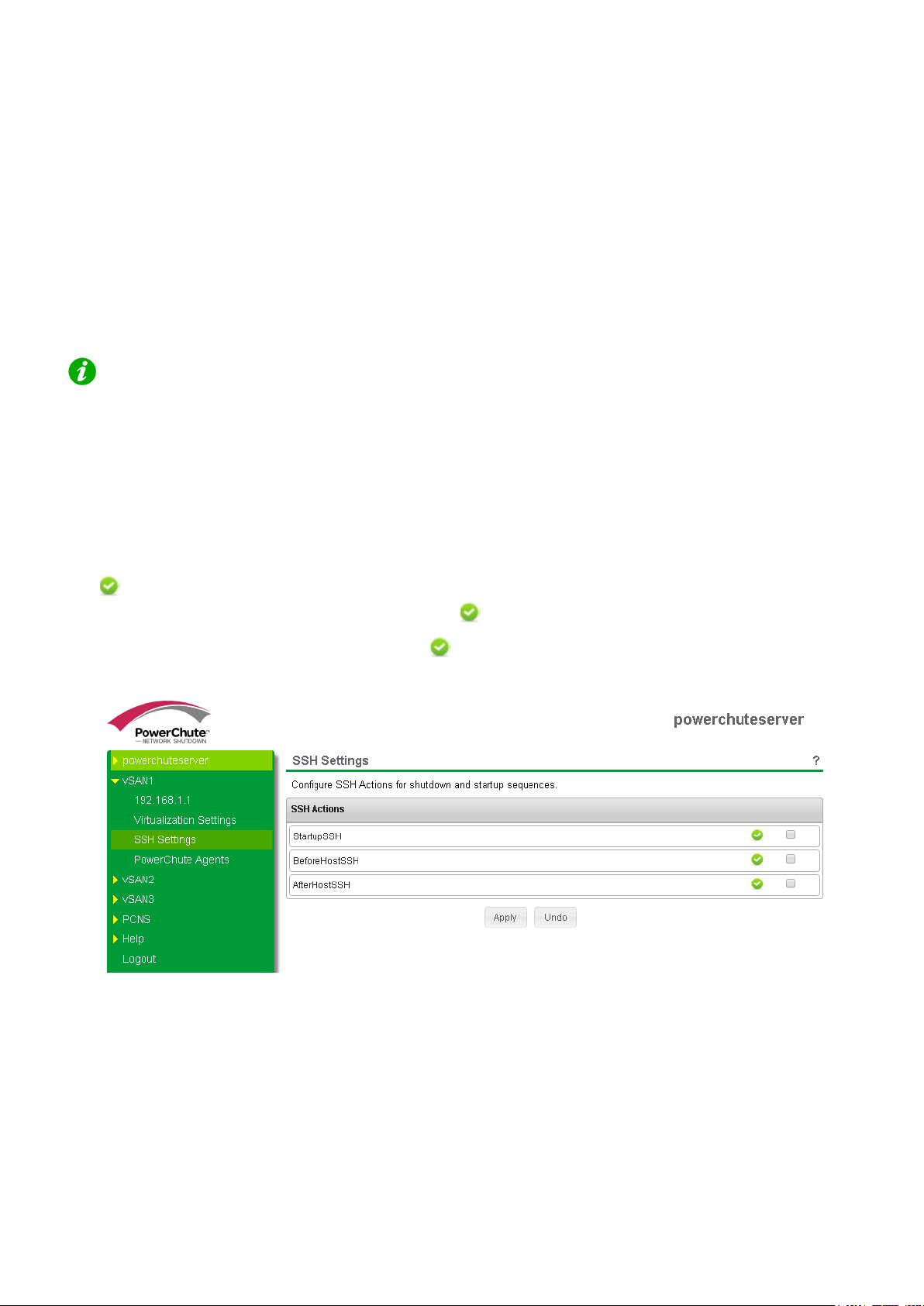
SSH Settings
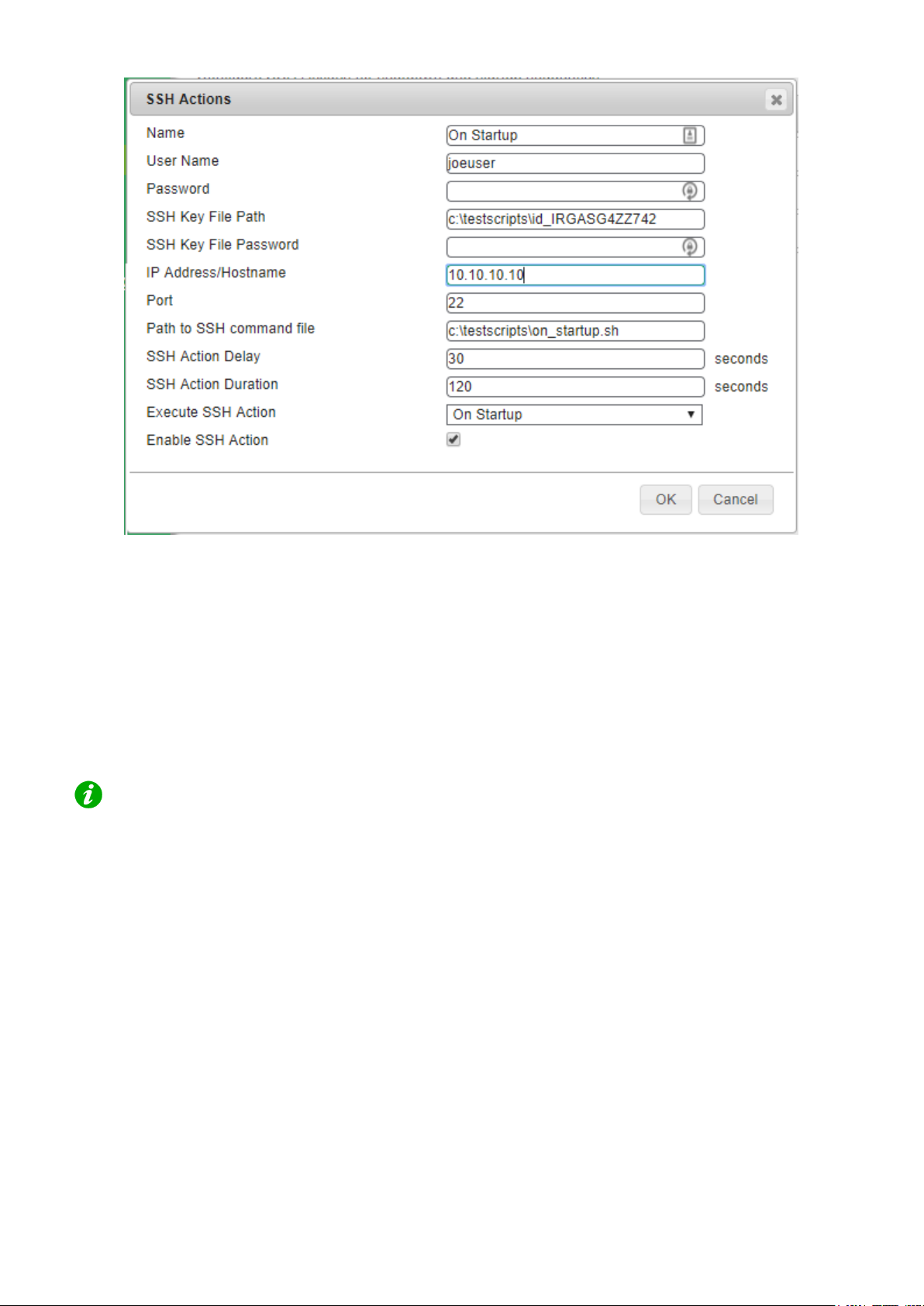
PowerChute Network Shutdown can be config ured to execute commands on a remote host via an SSH connection.
To create an SSH action, click Add Action and configure the following:
1. Name: A unique name for each SSH action of a length less than or equal to 255 ASCII characters.
2. Configure one of the following authentication methods:
• User Name and Password: Enter the user name and password to connect to the remote host.
• User Name, SSH Key File Path and SSH Key File Password: Specify the path to a shared SSH
key. This option requires you to generate an SSH key and c
SSH Command File Location.
3. IP Addresses/FQDN and Port: The IP address or Fully Qualified Domain Name (FQDN) and port of the
target SSH component.
4. Path to SSH command file: You must specify the full path name of the command file, including the disk
drive or volume number. See SSH Command File Location.
5. SSH Action Delay: Enter the amount of time, in seconds, that PowerChute will wait before connecting to
the remote host and begin sending commands. The default value is 0.
6. SSH Action Duration: Enter the amount of time, in seconds, for the SSH action to complete before
proceeding with the rest of the shutdown sequence.
opy it to your target systems. See
Using the SSH Action Duration fi eld, you must allow sufficient time for all your SSH
actions to complete.
7. Execute SSH Action:
• On Startup: Execute the SSH command file when the PowerChute service re-starts. In an
advanced configuration, the SSH command file is executed when the critical UPS event is
resolved.
• Before Host Shutdown: Execute the SSH command file before host shutdown.
• After Host Shutdown: Execute the SSH command file after host shutdown.
8. Enable SSH Action: Allows you to enable or disable the configured SSH action. This checkbox is enabled
by default when a new SSH action is created.
17
Page 22
SSH Settings
NOTES:
• PowerChute takes the command file provided and passes it line-by-line to the remote host
over an SSH connection. As a result, incomplete lines may be interpreted incorrectly by
the remote host. You must ensure that your SSH command file contains complete lines
and commands so the remote host can interpret the file correctly.
• The line ending style of the command file must match that of the PowerChute target host
operating system. For example, a command file configured on PowerChute running on a
Windows host must contain Windows style text line endings.
• Recognized command prompts are:
• $ (Linux)
• # (Linux admin/root)
• > (Windows, or RPDU)
• Custom command prompts can be added via the PowerChute configuration file
(pcnsconfig.ini) by adding the "ssh_prompt_regex" setting to the [SSHAction]
section. For example: to add a custom command prompt of "~", add
"ssh_prompt_regex = \~\s".
• The PowerChute Event Log only displays that an SSH action has completed. The Event
Log does not show if the SSH action has completed successfully or not.
• If a value is specified in the SSH Action Delay field, the Event Log does not log that an
SSH action is running with a configured delay.
18
Page 23
PowerChute Network Shutdown: Standard User Guide
SH Command File Location
S
The
PowerChute installation directory. If the default installation directory was chosen during installation, this location will
be:
• C:\Program Files\APC\PowerChute\user_files for Windows systems
• /opt/APC/PowerChute/user_files/ for Linux systems
key
SSH
NOTE: If you are upgrading to PowerChute v4.4, any key files and/or command files used in a
previous version of PowerChute must be manually added to the user_files folder. If the files
are not added to the directory, you will see the below errors in the Event Log:
ERROR: The ini contains an invalid value for ssh_command_file_path in
section SSHAction0.
ERROR: The ini contains an invalid value for ssh_keyfile_path in
section SSHAction0.
It is strongly recommended you validate your configuration after an upgrade.
file,
if
configured,
and
command
file
must be located in the user_files folder, or a sub-folder, in the
SSH Settings in an Advanced UPS Configuration
In an Advanced UPS configuration, SSH actions can be enabled and disabled for each UPS setup.
The symbol indicates that an SSH action is enabled in the main SSH Settings screen. To run an SSH action for
a particular UPS setup, enable the checkbox next to the
SSH actions that
enabled for a UPS setup.
are not enabled do not display the
symbol.
symbol. These disabled actions will not be executed if
19
Page 24

SNMP Configuration
PowerChute Network Shutdown can be config ured to communicate via Simple Network Management Protocol
(SNMP), and can be discovered via SNMP by Networ k Management tools, such as StruxureWare Data Center
Expert. Using SNMP, you can query and configure P owerChute settings, and generate SNMP traps for UPS critical
events and lost communication events.
SNMPv1 and SNMPv3 are supported by PowerChut e Net work Shutdown. IPv4 and IPv6 are both supported. Go to
SNMP Settings in the web user interface to complete the configuration and make PowerChute accessible via
SNMP. It is not necessary to re-start the PowerChute service when enabling SNMP or making SNMP configuration
changes via the web user interface. PowerChute c onfiguration changes via SNMP are logged to the Event Log.
Enter the SNMP Discovery Port. The default value of 161 is automatically populated, but this can be edited if this
port is already in use. The Port number availabili ty is automatically checked, and if it is not available, a new port
number must be entered.
See:
• SNMPv1 Configuration
NMPv3 Configuration
• S
• SN
• SN
• S
MP Trap Configuration
MP Data Points
NMP Troubleshooting
20
Page 25
PowerChute Network Shutdown: Standard User Guide
Certain Network Management Systems require t he S NMP Engine ID to communicate via SNMP.
The
SNMPv1 Configuration
Select Enable SNMPv1 access to configure the User Profiles required to communicate via SNMPv1. Select Add
Profile and configure:
1. Community Name: The Community Name is sent with each SNMP request to obtain access to a device.
The maximum length is 15 ASCII characters.
2. NMS IP/Host Name: The IP address, Host Name or Fully Qualified Domain Na m e of the Network
Management System (NMS). An NMS is software t hat is used to manage software and hardware
components on the network. It can be used to manage PowerChute via SNMP by issuing SNMP GET and
SET commands. The default value of 0.0.0. 0 permits access from any NMS.
3. Access Type:
• Disable: No SNMP GET or SET requests are permitted.
• Read: Only SNMP GET requests are permitted.
• Read/Write: SNMP GET and SET requests are permit ted.
To edit an existing SNMPv1 user profile, click the button. To delete an SNMPv1 user profile, click the
button.
Click Apply to save the SNMPv1 configuration.
SNMP Engine ID is displayed on the SNMP Settings page of the PowerChute user interface.
SNMPv1 is less secure than SNMPv3. SNMPv1 does not provide encryption or authentication,
and the Community Name is sent over the network in plain text. To use encryption and
authentication with SNMP, configure SNMPv3 settings.
21
Page 26

SNMP Configuration
SNMPv3 Configuration
Select Enable SNMPv3 access to configure the SNMPv3 settings. Select Add Profile and configure:
1. User Name: In SNMPv3, all GET and SET requests and SNMP Traps are matched to a user profile by the
User Name. Enter a user name of a length less than or equal to 32 ASCII characters.
2. Authentication Protocol
to use an SHA-2 protocol, if the NMS supports it.
It is not recommended to use the MD5 protocol.
3. Authentication Passphrase: Enter an authentication password for the protocol selected, of 8-32 ASCII
characters.
4. Privacy Protocol: Select AES-128, AES-192*, AES-192 Ex†, AES-256* , AES-256 Ex†, or DES. It is
recommended to use the AES-256 protocol, if the NMS and PowerChute JRE support it.
5. Privacy Passphrase: Enter a privacy password for the encryption protocol selected, of 8-32 ASCII
characters.
6. Access Type:
• Disable: No SNMP GET or SET requests are permitted.
• Read: Only SNMP GET requests are permitted.
• Read/Write: SNMP GET and SET requests are permitted.
: Select MD5, SHA-1 or SHA-2 (SHA256 or SHA512) protocol. It is recommended
button.
Click Apply to save the SNMPv3 configuration.
Certain Network Management Systems require t he S NMP Engine ID to communicate via SNMP.
The SNMP Engine ID is displayed on the SNMP Settings page of the Powe rChute user interface.
button. To delete an SNMPv3 user profile, click the To edit an existing SNMPv3 user profile, click the
22
Page 27

PowerChute Network Shutdown: Standard User Guide
SNMP Trap Configuration
You can specify the device(s) that receive the SNMP traps generated by PowerChute for UPS critical and lost
communication events.
To configure a Trap Receiver, select Add Trap Receiv er and configure:
1. Enable: Select the checkbox to enable the Trap Receiver.
2. NMS IP/Host Name: The IP address, Host Name or Fully Qualified Domain Name of the NMS.
3. Port: The port on which the NMS will listen for incoming traps. The default port number is 162.
4. SNMPv1: Select this if you want to send the traps via SNMPv1.
o Community Name: Enter the Community Name of the SNMPv1 user pr ofile to be used as an
identifier when SNMPv1 traps are sent to this receiver.
5. SNMPv3: Select this if you want to send the traps via SNMPv3.
o User Name: Select the user name of the SNMPv3 user profile to be used as an identifier when
SNMPv3 traps are sent to this receiver.
Click the SNMP Trap Receiver Test to send a test trap to the confi gured Trap Receiver. Check the Trap Receiver
to ensure that the test trap was received.
To edit an existing SNMP Trap Receiver, click the button. To delete an SNMP Trap Receiver, click the
button.
UPS Critical Events
PowerChute sends SNMP traps to the configured T rap Receiver(s) upon the following events:
• PowerChute Critical Event triggers a Shutdown
When a critical event (such as On Battery) occur s and a Shutdown is triggered, PowerChute sends an
SNMP trap detailing the Event Name, UPS Setup (for advanced configurations), and Affected Virtual
Hosts (if Virtualization support is enabled).
• PowerChute Critical Event Resolved
If the option to Send Trap when condition is cleared is enabled, when a P owerChute Critical Event which
triggered a Shutdown is resolved, PowerChute sends an SNMP trap to the configured NMS.
Lost Communication Events
PowerChute sends SNMP traps to the configured T rap Receiver(s) upon the following events:
• Network Communications Lost
If PowerChute cannot communicate with the Network Managem ent Card of the UPS, a trap is sent to the
configured Trap Receiver.
• UPS Communications Lost
If the Network Management Card cannot commu nicate with the UPS, a trap is sent to the configured Trap
Receiver.
If the option to Send Trap when condition is cleared is enabled, the following traps are sent:
• Network Communications Lost Resolved
If PowerChute regains communication with the Network Management Card of the UPS, a trap is sent to the
configured Trap Receiver.
23
Page 28

SNMP Configuration
• UPS Communications Lost Resolved
If communication is regained between the NMC and the UPS, a trap is sent to the configured Tr
R
eceiver.
Other Events
• Software Update Available Trap
When the PowerChute Auto Update functionality det ects that there is a new update available; a trap is sent
to the configured Trap Receiver.
• PowerChute Test Trap
When configuring a Trap Receiver, a test trap can be sent to determine if the Trap Receiver is receiving th
raps. See SNMP Trap Receiver Test.
t
ee SNMP Data Points > PowerChute Traps for more information on PowerChute SNMP Trap OIDs.
S
Configuring SNMP Trap Notification Settings
To configure the settings for UPS Critical Event or Lost Communication traps:
ap
e
1. Go to SNMP Settings > SNMP Traps
2. Click on the icon next to UPS Critical Events or Lost Communication Events
3. Select the Enable checkbox to enable traps for critical events.
4. Delay: Specify the length of time that Event must persist before a trap i s s ent. If the Event is cleared befor
his time, no trap is sent.
t
5. Repeat Interval: Specify the time interval i n seconds that the trap is re-sent.
6. Select:
• Repeat until condition clears if you want the trap to be sent at the repeat interval until the Event
is cleared.
• Repeat X times to specify the number of times the trap will be sent when the Event occurs.
7. Select Send Trap when condition is cleared to be notified when the Event is cleared.
Note: If the PowerChute server is shut down due to a UPS Critical Event, no clearing Trap will be sent t
he NMS.
t
o
e
24
Page 29

PowerChute Network Shutdown: Standard User Guide
pcnsUIProtocol
The web protocol that is used to connect to the PowerChute
SNMP Data Points
The tables below describe the PowerChute configu rat ion details that are available for SNMP polling and/or
configuration.
PowerChute Identity Information
Object Identifier
Name
pcnshostname read-only The hostname of the PowerChute instance.
pcnsVersion read-only The version of PowerChute installed.
pcnsOS read-only The version of the Operating System upon which
pcnsJavaVersion read-only The version of Java upon which PowerChute is running.
Access Description
PowerChute is installed.
PowerChute Networking Settings
Object Identifier
Name
Access Description
read-only
web user interface.
pcnsHttpPort read-only The port that is used to connect to the PowerChute web
user interface.
pcnsHttpsPort read-only The port that is used to connect via https to the PowerChute
web user interface.
pcnsNetworkConfig read-only Config urat i on of the TCP network: IPv4/IPv6.
pcnsVirtualInstall read-only The Virt ualization technology for which PowerChute is
configured.
25
Page 30

PowerChute Network Management Card Settings
triggered. See Shutdown Command Files.
Shutdown Command Files.
the UPS drops below the threshold,
SNMP Configuration
Object Identifier
Name
pcnsMode read-only
pcnsNMCPort read-only The port used to connect to all of the Network Management
pcnsNMCProtocol read-only The web protocol used to connect to all of the Network
NMC details are contained in an SNMP table named pcnsNmcTable. Each table entry contains:
pcnsNMCIndex read-only The Index of the NMC within the PowerChute setup.
pcnsNMCAddr read-only The IP address of the NMC
pcnsNMCOutlet read-only The Outlet Group of the NMC on which PowerChute is
Access Description
The configuration of the UPSs that PowerChute is
monitoring. See UPS Configuration Options.
Card(s).
Management Card(s).
enrolled.
PowerChute Shutdown Settings
Object Identifier Name Access Description
pcnsShutdownCommandFileEnabled* read-
write
pcnsShutdownCommandFileDelay* read-
write
pcnsShutdownCommandFile* read-
write
pcnsShutdownCommandFileDuration* read-
write
pcnsTurnOffUps* read-
write
Specify if Shutdown a Command File is
configured to run if a UPS critical event is
The number of seconds that a host requires
to shut down, before the command file is
executed. This setting is applicable to
virtualization support only.
The full path name of the command file,
including the disk drive or volume name. See
The number of seconds that the shutdown
command file requires to execute.
The setting to turn off the UPS after
performing a graceful shutdown.
pcnsTurnOffSOG* read-
pcnsRuntimeRemainingThreshold read-
write
write
The setting to turn off the Outlet Group of the
UPS when performing a graceful shutdown.
This defines a threshold for runtime
remaining. When the UPS in running on
battery power and the runtime remaining on
26
Page 31

PowerChute Network Shutdown: Standard User Guide
information.
* Note: These OIDs are not available for Advanced UP S S etups. See below for equivalent OIDs for
Advanced UPS Setups.
PowerChute triggers a shutdown sequence.
See Sequenced Server Shutdown
for more
pcnsRuntimeRemainingCmdFileThreshold read-
write
This defines a threshold for runtime
remaining. When runtime remaining drops
below this threshold, PowerChute executes
the command file.
PowerChute Events
The table below details the OID Names of the Configurable Events that can be configured via SNMP, and the
names of the Events as seen in the PowerChute User Interface.
Object Identifier Name PowerChute UI Reference
pcnsPowerFailed UPS On Battery
pcnsPowerRestored Input Power Restored
pcnsOverload UPS Overloaded
pcnsOverloadSolved UPS Overload Corrected
pcnsRunTimExceeded Runtime exceeded
pcnsRunTimeWithinRange Runtime is sufficient
pcnsRunTimeBelowThreshold Runtime remaining below threshold
pcnsRunTimeAboveThreshold Runtime remaining above threshold
pcnsBatteryDischarged Battery Discharged
pcnsBatteryChargeInRange Battery Recharged
pcnsFaultBypassEnabled Bypass due to hardware error or overload
pcnsBypassEnabled Maintenance Bypass
pcnsBypassManualEnabled Bypass ended
pcnsBypassDisabled Bypass ended
pcnsBypassContactorFailed Bypass Switch failed
27
Page 32

pcnsBypasContactorOk Bypass Switch replaced
pcnsCommunicationLostOnBattery Communication lost while on Battery
pcnsCommunicationLost NMC cannot communicate with the UPS
SNMP Configuration
28
Page 33

PowerChute Network Shutdown: Standard User Guide
pcnsContactFaultX
Object Identifier Name PowerChute UI
Reference
pcnsNetCommunicationLost PowerChute cannot
communicate with the NMC
pcnsCommunicationEstablished Communication established
pcnsMinRedundancyLost Minimum Redundancy lost
pcnsMinRedundancyRegained Minimum Redundancy restored
pcnsParallelRedundancyLost Parallel Redundancy lost
pcnsParallelRedundancyRegained Parallel Redundancy restored
pcnsMaxInternalTempExceeded UPS Temperature Overheated
pcnsMaxInternalTempInRange UPS Temperature Normal Again
pcnsMinLoadCapabilityLost Load (kVA) Alarm Violation
pcnsMinLoadCapabilityRegained Load (kVA) Alarm Violation
cleared
pcnsEnviornmentCommunicationEstablished Communication Established with
EMC
pcnsEnviornmentCommunicationLost Communication Lost with EMC
pcnsTempInRangeProbeX Temperature Probe X In Range
pcnsTempOutOfRangeProbeX Temperature Probe X Out Of
Range
pcnsHumidityInRangeProbeX Humidity Probe X In Range
pcnsHumidityOutOfRangeProbeX Humidity Probe X Out Of Range
Contact Zone X Alarm
pcnsContactNormalX Contact Zone X Normal
29
Page 34

For each event you can access:
[event name]Desc
[event
[event
[event
[event
See pcnsRunTimeBelowThresholdCommandFileThreshold.
[event
[event name]ShutdownDelay
pcnsRunTimeBelowThresholdCommandFileThreshold
If Runtime Remaining falls
pcnsRunTimeBelowThresholdShutdownThreshold
OID Name Access Description
SNMP Configuration
read-
The description of the event.
only
name]EnableLogging
read-
Enable or disable logging to the event log for this eve nt.
write
name]EnableCommandFile
read-
Enable or disable command file execution for thi s ev ent.
write
name]CommandFilePath
name]CommandFileDelay
readwrite
readwrite
Specify a Command File and full path to be executed upon
this event.
The number of seconds that a host requires to shut down,
before the command file is executed.
Note: This is not available for pcnsRunTimeBelowThreshol d.
For some events you can access:
OID Name Access Description
name]EnableShutdown
read-write Perform a graceful shutdown of
the host when this event occurs.
read-write The amount of time in seconds
that PowerChute should wait
before initiating the shutdown
process.
For pcnsRunTimeBelowThreshold you can access:
OID Name Access Description
readwrite
readwrite
below this threshold, the
command file is executed.
If Runtime Remaining falls
below this threshold, a
graceful shutdown of the host
is initiated.
30
Page 35

PowerChute Network Shutdown: Standard User Guide
PowerChute Traps
The table below details the OID Names of the SNMP t raps sent by PowerChute for critical and lost communication
events.
UPS Critical Events
OID Name Level Description
pcnsCriticalEventActive Severe PowerChute Network Shutdown has begun a graceful shutdown of
the host due to a critical event.
pcnsCriticalEventResolved Informational The PowerChute Network Shutdown critical ev ent has been
resolved, and graceful shutdown of the host continues.
Lost Communication Events
OID Name Level Description
pcnsNetworkComsLost Severe PowerChute cannot communicate with the NMC.
pcnsNetworkComsLostResolved Informational PowerChute has regained communication with the NMC.
pcnsNMCComsLost Severe The NMC cannot communicate with the UPS.
pcnsNMCComsLostResolved Informational The NMC has regained communication with the UPS.
Other Events
OID Name Level Description
pcnsTest Informational PowerChute has sent a test trap to the NMS.
pcnsUpdateAvailable Informational PowerChute has detected that an update is available.
31
Page 36

Event Configuration
Descriptions of events are in the
When UPS events occur, PowerChute can be conf i gured to log the event, notify users, execute a command file or
initiate a system shutdown through the Configure E vents screen.
The symbol indicates that the action is enabled for this event while the symbol indicates t hat the action is
not enabled.
PowerChute Events and Logging sections.
32
Page 37

PowerChute Network Shutdown: Standard User Guide
Notifications
PowerChute can send a message to one user or all logged-i n users when an event occurs:
Notify all users: For Windows, the message will be sent to al l users who are on the same network. For Linux or
Unix, all users who are logged onto the server with a terminal prompt open will be notified.
Notify only this user: On Windows, enter the machine name. On Linux or Unix systems, enter the user name. The
user will still need to be logged onto the server with a terminal prompt open to be notified.
Repeat Interval: The time interval, in seconds, at which the message will be repeated while the event condition
exists. If this field is blank or zero, the message wil l not be repeated.
Delay (if required): Enter the amount of time in seconds that P owerChute should wait after the event occurs
before notifying users. Users will be notified immediately if a shutdown event is triggered.
For Windows operating systems, PowerChute can onl y send not ifications if the operating system
supports the messenger service. If not supported, there is no option displayed in the UI. See
Knowledge Base article FA169440 for more information. (If you have difficulty with this link,
enter "FA169440" at https://www.apc.com/us/en/faqs/home/).
33
Page 38

Event Configuration
Event-Driven Command Files
If required, PowerChute can be configured to execute a command file after certain events are triggered. Click the
symbol on the event row and select the Enable Command File check box .
Delay: Enter the amount of time in seconds that PowerChute should wait when the event occurs before executing
the command file.
If a shutdown command file is also configured, both command files will be executed in parallel.
Full path to command file: You must specify the full path name of the command file, including the disk drive or
volume name.
The command file runs using the local system account. PowerChute cannot execute programs that require
interaction with the desktop; only command line-enabled programs are supported.
The command file must be located in the user_files folder, or a sub-folder, in the PowerChute installation
directory. If the default installation directory was chosen during installation, this location will be:
• C:\Program Files\APC\PowerChute\user_files for Windows systems
• /opt/APC/PowerChute/user_files/ for Linux systems
NOTE: If you are upgrading to PowerChute v4.4, any command files used in a previous version of
PowerChute must be manually added to the user_files folder. If the command files are not added to the
directory, you will see the below errors/warnings for all events configured to run a command file in the
Event Log. For example:
ERROR: Event PowerFailed is enabled for command file execution, but an
invalid value for event_PowerFailed_commandFilePath is specified.
WARNING: Disabling command file execution for event PowerFailed due to bad
parameters. Please validate the configuration.
It is strongly recommended you validate your configuration after an upgrade.
34
Page 39

PowerChute Network Shutdown: Standard User Guide
Shutdown Actions
When the Shutdown Action is enabled for an event, PowerChute treats the event as critical and will trigger a
shutdown sequence. Shutdown is not supported for all events: this is indicated by the presence or absence of an
icon on the event row.
The Delay field is the amount of time in seconds that PowerChute should wait before initiating the shutdown
sequence. By default, the On Battery event has a delay of 120 seconds, whereas the default for all other events is
0 seconds.
By default, PowerChute will only trigger a shutdow n sequence if a low battery condition occurs or the UPS is
commanded to turn off. Shutdown cannot be disabl ed for these events using the PowerChute user interface.
35
Page 40

Sequenced Server Shutdown
The Runtime Remaining below Threshold event can be used to sequence the order that your servers shut down
during an extended power outage.
This is useful if you have multiple servers powered by the same UPS and you want to extend the runtime for your
higher priority servers. It also ensures that lower priority servers are the first to be shut down.
This event will trigger a server shutdown command when the UPS is running on battery power and the runtime has
dropped below the threshold configured. You can also configure a command file to execute before shutdown
occurs by specifying a higher runtime threshold valu e f or the Run Command File event action.
Example
1. You have 3 servers powered by the same UPS. Your lowe r priority server is Server C while you want to
keep Server A running as long as possible.
2. You want Server A to shut down when the UPS protecting it has 10 minutes runtime remaining.
3. You want Server B to shut down when the UPS protecting it has 15 minutes runtime remaining.
4. You want Server C to shut down when the UPS protecting it has 20 minutes runtime remaining.
5. Configure each PowerChute Agent with the fol l owing threshold values:
o Server A – 10 minutes
o Server B - 15 minutes
o Server C - 20 minutes
6. Each server is shut down when the runtime remaining drops below the threshold configured.
36
Page 41

Sample Shutdown Scenari os
The following scenarios provide examples of how P owerChute and the UPS behave when a shutdown sequence is
triggered.
37
Page 42

Sample Shutdown Scenarios
UPS without Outlet Groups
Example 1: Turn of UPS enabled, No shutdown command file configured.
The option to Turn off the UPS is enabled on the Shut down settings page. No shutdown command file is
configured.
When a critical UPS event, such as On Battery occur s, the following sequence is triggered.
1. PowerChute reports that the UPS is on battery.
2. After the shutdown delay configured for the On Bat tery event has elapsed, PowerChute sends a command
to turn off the UPS.
3. PowerChute starts the operating system shutdown se quence.
4. After a 70 second delay the operating system start s t o shut down.
5. The UPS will wait the amount of time indicated by one of the following, whichever is greater: Low Battery
Duration or Maximum Required Delay
These are shown on the UPS Shutdown page in the NMC UI.
6. After this delay, a further non-configurable two mi nut e delay is counted down.
7. The UPS will then turn off after the user-configurable Shutdown Delay time has elapsed
This is configurable on the UPS Shutdown page in the NMC UI.
It is recommended that the Low Battery Duration i s configured to allow enough time for the Operating System
shutdown to complete. Ideally the operating system should have shut down before the non-configurable two minute
delay (step 6) starts to count down.
38
Page 43

PowerChute Network Shutdown: Standard User Guide
Example 2: Turn off UPS enabled, shutdown command file configured.
The option to Turn off the UPS is enabled on the Shut down settings page. A shutdown command file is configured.
When a critical UPS event, such as On Battery occur s, the following sequence is triggered.
1. PowerChute reports that the UPS is on battery.
2. After the shutdown delay configured for the On Bat tery event has elapsed, PowerChute then sends a
command to turn off the UPS. UPS turn off starts.
3. PowerChute starts to execute the shutdown command file.
4. After the duration configured for the shutdown command file has elapsed, an additional 70 second delay is
counted down before the operating system starts to shut down.
5. The UPS will wait the amount of time indicated by one of the following, whichever is greater: Low Battery
Duration or Maximum Required Delay. These are shown on the UPS Shutdown page in the NMC UI.
6. After this delay, a further non-configurable two minute delay is counted down.
7. The UPS will then turn off after the user-configurable Shutdown Delay time has elapsed (this is
configurable on the UPS Shutdown page in the NMC UI ).
It is recommended that the Low Battery Duration is configured to allow enough time for the shutdown command
file and operating system shutdown to complete. Ideally, the operating system should have shut down before the
two minute delay (step 6) starts to count down.
39
Page 44

Sample Shutdown Scenarios
UPS with Outlet Groups
Example 1: Turn off Outlet Group enabled, no shutdown command file configured.
The option to Turn off the Outlet Group is enabled o n the Shutdown settings page. No Shutdown command file is
configured.
When a critical UPS event, such as On Battery occur s, the following sequence is triggered.
1. PowerChute reports that the UPS is on battery.
2. After the shutdown delay configured for the On Battery event has elapsed PowerChute sends a command
to turn off the outlet group that PowerChute is regi st ered with.
3. PowerChute starts the operating system shutdown sequence.
4. After a 70 second delay the operating system starts to shut down.
5. The outlet group will turn off after the Power Off Delay configured on the NMC Outlet Group configuration
page has elapsed.
o If registered with the Main Outlet Group, the UPS will wait for any Switched Outlet G roups to turn
off before the Main Outlet Group turnoff starts.
o If registered with a Switched Outlet Group, only that delay is counted down.
40
Page 45

PowerChute Network Shutdown: Standard User Guide
It is recommended that the outlet group Power Off Delay is configured to allow enough time for the operating
system shutdown to complete. You should allow extra time to ensure that the outlet group does not turn off before
the operating system.
41
Page 46
Sample Shutdown Scenarios
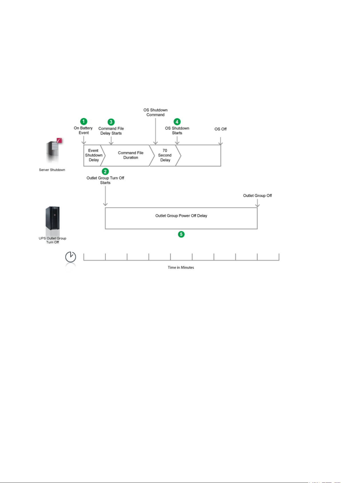
Example 2: Turn off the Outlet Group enabled, shutdown command file configured.
The option to Turn off the Outlet Group is enabled on the Shutdown settings page. A shutdown command file is
configured.
When a critical UPS event, such as On Battery occur s, the following sequence is triggered.
1. PowerChute reports that the UPS is on battery.
2. After the shutdown delay configured for the On Battery event has elapsed, PowerChute then sends a
command to turn off the outlet group that it is registe red with. Outlet Group turn off starts.
3. PowerChute starts to execute the shutdown command file.
4. After the duration configured for the shutdown command file has elapsed, an additional 70 second delay is
counted down before the operating system starts to shut down.
5. The Outlet Group will turn off after the Power Off Delay configured on the NMC Outlet Group configuration
page has elapsed.
o If registered with the Main Outlet Group, the UPS will wait for any Switched Outlet groups to t urn
off before the Main Outlet Group turn off starts.
o If registered with a Switched Outlet Group only that delay is counted down.
It is recommended that the Outlet Group Powe r Off delay is configured to allow enough time for the shutdown
command file and the Operating System shutdown t o complete. You should allow extra time to ensure that the
Outlet Group does not turn off before the Operating System.
42
Page 47

PowerChute Network Shutdown: Standard User Guide
The Low Battery Duration set on the NMC should be equal to or greater than the Power Off Delay
Recommended Power-Off Delays for Outlet groups
By default, the outlet group Power Off Delay will be the same value as the Low Battery duration configured on t he
NMC. PowerChute will automatically increase t he Power Off Delay for the outlet group it is registered with, if the
total shutdown time it needs is greater than the Power Off Delay.
The total shutdown time includes the following values:
• Shutdown Command File Duration
• Built-in delay of 2 minutes (this consists of a 10 second OS shutdown delay and a 60 second OS shutdown
duration; rounded up)
The time required to gracefully shut down your operating system is not covered by the total
shutdown time, as PowerChute cannot determine how long it will take to complete.
The Power Off Delay for the outlet group should be long enough for the OS to gracefully shut
down. You should add extra time to allow for unfores een circumstances.
for the outlet group.
43
Page 48

PowerChute Events and Logging
1000 is the default value, but you can change it using the PowerChute Configuration (INI) File. To
do this:
The Event Log displays UPS events that affect P owerChute and the load that it is protecting. Not all UPS events
are logged. The log is refreshed automatically every 30 seconds.
By default, event logging is enabled for all configurable and non-configurable PowerChute events. To disable
logging of an event, use the Configure Events screen.
The EventLog.txt file is located in the group1 folder where PowerChute is installed. When the file reaches 1000
log entries, the oldest third of the file is deleted.
1. Stop the PowerChute service/daemon. For more information, see Knowledge Base article
FA290624 (Enter "FA290624" at https://www.apc.com/us/en/faqs/home/).
2. Locate the pcnsconfig.ini file in the group1 folder where PowerChute is installed and
open it using a text editor.
3. In the section [EventLog] change the value for logsize to the desired value. For
example, to change the value to 2000 entries, change logsize to:
logsize = 2000
4. Save the pcnsconfig.ini file.
5. Restart the PowerChute service/daemon.
To completely clear the Event Log, use the Delete Log File button. Use Export Log to download a copy of the
Event Log as a text file.
44
Page 49

PowerChute Network Shutdown: Standard User Guide
Configurable Events
• Available runtime has been exceeded
For both conditions below, the “total shutdown time” includes the following durations:
• Shutdown command file duration
• SSH action duration
• Built-in duration of 2 minutes (this consists of a 10 second OS shutdown duration and a 60 second OS
shutdown duration; rounded up)
his event occurs with either of the following conditions:
T
Condition 1.
When the total shutdown time required by PowerChute is greater than the Low Battery Duration minus two
minutes configured for the UPS. In the event of a low bat tery condition, PowerChute will not have enough time to
complete the shutdown sequence before the UPS po wers off. For example, if the total shutdown time required is 3
minutes and Low Battery Duration is 4 minutes, the Available Runtime has been Exceeded event will be triggered.
Resolution: Increase the Low Battery Durati on value on the NMC using Configure - Shutdown or decrease the
shutdown durations being used by PowerChute.
Condition 2.
When the shutdown duration configured for the UPS On B attery event plus the total shutdown time required by
PowerChute is greater than the Runtime Remaining on the UPS minus two minutes. This condition can be caused
by having too great a load on the UPS when the battery i s f ul l y charged.
Resolution:
1. Remove some equipment from the UPS to increase t he available runtime.
2. Decrease the shutdown duration time for the UP S On Battery event.
3. Decrease the command file execution time using t he Shutdown Settings screen.
This event is logged and event actions are carried out even if it occurs on a single UPS in a Redundant or Parallel
UPS configuration.
•
Available runtime is sufficient
available UPS Runtime/ Low Battery Duration is sufficient for PowerChute to shut down all equipment
The
gracefully.
•
Battery is discharged
The
UPS battery runtime has fallen below an acceptable range. If there is a power outage, a low battery condition
will occur. This can be caused if the UPS has been o perat i ng on battery for an extended time period.
If a Battery Recharged event does not occur within four hour s, t he UP S may not be charging properly, please
contact APC Customer Support.
•
Battery has recharged.
The
battery runtime of the UPS has returned to withi n an acceptable range.
45
Page 50

PowerChute Events and Logging
•
UPS in Bypass due to an internal hardware problem or UPS overload.
The UPS has switched to bypass due to an internal hardware problem or because the UPS is overloaded.
UPS has switched to bypass in response to the bypass switch at the UPS, typically for
•
maintenance.
A user put the UPS into bypass mode using a hardware s wit ch.
UPS has switched to bypass in response to the UPS front-panel or a user-initiated software
•
command, typically for maintenance.
The UPS has switched to bypass and cannot protect the load if a power outage occurs. This is a normal condition
if maintenance is being performed on the UPS.
If this event occurs when the UPS was not deliberately put into bypass, please contact Customer Support.
•
UPS is no longer in Bypass.
The UPS is no longer in a bypass state.
•
Bypass switch is not working properly.
The bypass contactor is not operating properly. This will prevent the UPS from being placed in bypass or returning
from bypass. Please contact Customer Support.
•
Bypass switch has been replaced.
The bypass contactor is now operating properly.
•
Communication has been lost while on battery.
PowerChute lost communication while the UPS was on battery and cannot detect a Low Battery condition if t he
power outage continues. Graceful shutdown cannot be guaranteed.
This occurs when the UPS is on battery and:
• The Management Card cannot communicate with the UPS
or
• PowerChute cannot communicate with the Mana gement Card.
•
Network Management Card cannot communicate with the UPS.
Communication between the NMC and the UPS has been lost. Make sure that the NMC is firmly inserted in its
slot. This can occur during a firmware upgrade of the NMC.
•
PowerChute cannot communicate with the Network Management Card.
Network communication between PowerChute and t he NMC has been lost. See Network Management Card
Troubleshooting. This can occur during a firmware upgrade of the NMC.
46
Page 51

PowerChute Network Shutdown: Standard User Guide
•
Communication has been established.
Communication has been established between PowerChute and the NMC.
UPS has switched to battery power.
•
The UPS has switched to battery operation due to a power outage. If you can’t restore power to the UPS, do the
following:
1. If there is no general power outage (i.e. if only t his UPS has lost input power), check the building wiring and
circuit breakers.
2. If this event occurs occasionally and briefly , check to see if equipment on the same electrical circuit as the
UPS uses high power periodically.
3. This event can also be caused by poor power quality (i.e. power fluctuation). Decrease the sensitivity of the
UPS through the NMC user interface.
4. If the condition persists, contact an electricia n to analyze your utility power.
•
UPS is no longer running on battery power or output power has been turned on.
The UPS is no longer running on battery power.
•
The load has exceeded the user specified alarm threshold.
The load on your UPS has exceeded the maximum load threshold, set in the NMC user interface. Reduce the load
on the UPS or upgrade to a device that can support the existing load.
•
The load no longer exceeds the user specified alarm threshold.
The load on your UPS is no longer above the load threshold.
Minimum redundancy lost.
•
The UPS has too great a load or there are not enough pow er m odules operational to support the desired
redundancy.
Check to see that all power modules are functioning properly and that the redundancy configuration is correct.
If the condition persists, contact Customer Support.
•
Minimum redundancy restored.
The UPS can now support the desired redundancy.
Parallel redundancy lost.
•
The system has too great a load or there are not enough operational UPS’s to support the desired redundancy
level.
Check to see that all UPS’s are functioning properly and that the redundancy configuration is correct.
If the condition persists, contact Customer Support.
47
Page 52

PowerChute Events and Logging
•
Parallel redundancy restored.
The Parallel UPS system can now support the desired red undancy.
The runtime remaining has dropped below the configured threshold while on Battery.
•
The runtime remaining has dropped below the configured threshold while on battery. You can configure this
threshold using the shutdown action on the Config ure Events page.
When the UPS in running on battery power and the runtime remaining on the UPS drops below the threshold,
PowerChute will trigger a shutdown sequence. S ee “Sequenced Server Shutdown” for more information.
•
The runtime remaining is now above the configured threshold or input power has been restored.
Occurs when the UPS runtime is greater than the user defined threshold or if the UPS is no longer running on
battery power.
•
UPS has overheated which can cause damage.
The UPS’s internal temperature is too high. Make sur e t hat there is at least one inch of clearance around the UPS,
and that the UPS ventilation ports are not blocked. I f this condition is not resolved quickly, damage may occur to
your UPS.
•
UPS is no longer overheated.
The UPS’s internal temperature has returned to an a cc ept able level.
UPS output overload.
•
The UPS has sensed a load greater than 100 per cent of its rated capacity. Remove attached equipment from the
UPS until the condition is corrected. If this condit i on happens occasionally and briefly, check to see if some
equipment connected to the UPS is using high power periodically (e.g. connected laser printers or photocopiers).
If the condition persists, contact Customer Support.
•
UPS overload condition has been corrected.
A condition that caused the UPS output overload event to occur has been corrected.
48
Page 53

PowerChute Network Shutdown: Standard User Guide
Configurable Environmental Events
The following events are logged and event actions are carried out even if they occur on a single UPS in a
Redundant or Parallel UPS configuration.
Ambient Temperature Out Of Range Probe X.
•
The temperature exceeds the threshold configured for the Environmental temperature probe.
Ambient Temperature In Range Probe X.
•
The temperature no longer exceeds the threshold configured for the Environmental temperature probe.
Humidity out of Range Probe X.
•
The humidity exceeds the threshold configured for the Environmental humidity probe.
Humidity In Range Probe X.
•
The humidity no longer exceeds the threshold conf igured for the Environmental humidity probe.
Communication lost with Environmental Monitor.
•
PowerChute has stopped receiving data from t he Environmental Monitoring Card or the probe has been remov ed
from the Universal I/O (UIO) port on the NMC.
Check to see that the Environmental Monitoring Card is firmly inserted in its slot and has power. Check that
environmental monitoring information is ac ce ssi b le through the NMC user interface.
If PowerChute cannot communicate with the NMC you will need to correct that problem first.
•
Communication established with the Environmental Monitor.
PowerChute Network Shutdown is receiving dat a f rom the Environmental Monitoring Card/Probe.
Contact X Alarm.
•
One of the environmental input contacts is in an alar m st at e. Check in the location being monitored by this
contact.
•
Contact X Normal.
One of the environmental input contacts has returned to a normal condition.
49
Page 54

PowerChute Events and Logging
Non-Configurable Events
• Three unsuccessful logon attempts detected. Temporarily denying logon att em pts from machine
with IP <IP address>.
There have been three invalid login attempts from a machine with the IP address listed in the event. Further login
attempts will be prevented from this machine for t wo minutes. This is a security measure designed to prevent
brute-force login attempts.
•
Username was changed by user [User] from IP address [IP address]. New username is
[Username].
The Username has been changed by the user at the specifi ed IP address. This is a security feature to notify the
user when the Username has been changed.
•
Password was changed by user [User] from IP address [IP address].
The password has been changed by the user at the specified IP address. This is a security feature to notify the
user when the password has been changed.
•
Authentication phrase was changed by user [User] from IP address [IP address].
The authentication phrase has been changed by the user at the specified IP address. This is a security feature to
notify the user when the authentication phrase has been changed.
•
Low-battery condition occurred.
The runtime remaining on the UPS has dropped belo w t he Low battery duration value while the UPS was on
battery.
•
UPS Turn off has been initiated.
A graceful shutdown command has been issued to the UPS using the NMC User Interface, the LCD display or by
PowerChute. This event is logged for all UPS Configurations.
•
PowerChute Network Shutdown version X monitoring started.
The PowerChute Web service has been started.
•
Shutdown process started ‹OS name› will shut down soon.
The operating system has started to shut down in response to a critical UPS event.
•
Error: Outlet Group X is turned off for NMC X.
The outlet group that PowerChute is registered with is turned off. This can indicate that PowerChute is not
configured for the correct outlet group.
50
Page 55

PowerChute Network Shutdown: Standard User Guide
•
Warning: Outlet Group X is turning off for NMC X.
The outlet group that PowerChute is registered with is shutting down. A shutdown sequence will be started as a
result.
•
No Outlet Group specified. Using outlet group X.
If PowerChute was not registered with an Outlet group during setup it will be automatically registered with the first
outlet group on the UPS by default.
•
PowerChute is unable to open TCP port [number]. Check that TCP port [number] is free.
PowerChute uses TCP ports 3052 and 6547 for the Web User Interface. This event will be logged if another
application is already using either of the above port s.
Use the netstat command to identify which process is using these ports or change the values using the
PowerChute Configuration File.
•
PowerChute is attempting to open TCP port [number]
PowerChute has begun to open the port it requires f or the Web UI.
•
PowerChute successfully opened TCP port [number].
PowerChute has successfully opened the port it requires for the Web UI.
PowerChute is unable to open UDP port 3052. Check that UDP port 3052 is free. This is
•
required for NMC communication.
PowerChute uses UDP port 3052 for communicati on with the NMC. This event will be logged if another application
is already using this port. Use the netstat command t o i dentify which application is using the port. This port cannot
be changed.
•
PowerChute is attempting to open UDP port 3052.
PowerChute has begun to open the port required for NMC communications.
PowerChute successfully opened UDP port 3052.
•
PowerChute was able to open the port it needs for N M C co m m unications.
PowerChute cannot communicate with Network Management Card [ip_address]
•
Reported when the PowerChute Agent cannot communicate with the Network Management Card over the
network. This could be due to a mismatch in security c redentials or a network issue.
•
Network Management Card [ip_address] cannot communicate with the UPS.
Reported when the Network Management Card cannot communicate with the UPS. If this issue persists please
contact technical support.
51
Page 56

PowerChute Events and Logging
• Connection unsuccessful because PowerChute received an untrusted SSL certificate from the
NMC
[protocol]://[ip_address]
This can occur if registering with an NMC that has HTTPS enabled and is using an SSL certificate that is not signed
by a trusted root certification authority.
To accept the certificate, enable the option "Accept Untrusted SSL Certificates?" on the UPS Details page of the
PowerChute Setup Wizard or add the certificate to the PowerChute-keystore.
• PowerChute received an untrusted SSL certificate from the NMC https://[ip_address].
Occurs when registering with an NMC that has HTTPS enabled if the SSL cert is not signed by a trusted root
certification authority.
• PowerChute added a Network Management Card Self-Signed Certificate to the keystore.
If the option Accept Untrusted SSL certificates is enabled, PowerChute will automatically add self-signed and
untrusted certs to its local keystore.
• UPS [ip_address] is running on battery power
Reported when one UPS goes on battery in a UPS configuration with multiple UPS's.
• The On Battery UPS is no longer running on Battery power or output power has been turned on.
Reported when one UPS in a UPS configuration with multiple UPS's returns to On Line operation.
• Outlet on UPS is turning off / UPS is turning off.
The advanced option is enabled under UPS Shutdown Settings for a Redundant UPS Configuration and one UPS
is on Battery.
• UPS [ip_address] has turned off.
Reported when one UPS turns off in a UPS configuration with multiple UPS's.
• The turned off UPS has switched to On Line operation.
Reported when one UPS turns back on in a UPS configuration with multiple UPS's.
• Multiple UPS's have been commanded to turn off / Outlet Group turn off has been initiated on
Multiple UPS's.
Reported in a Redundant UPS Configuration.
In n+1 redundancy, this is reported when 2 UPS's turn off.
In n+2 redundancy, this is reported when 3 UPS's turn off.
In n+3 redundancy, this is reported when 4 UPS's turn off.
52
Page 57

PowerChute Network Shutdown: Standard User Guide
• Multiple UPS have turned off.
Reported in a Redundant UPS Configuration.
In n+1 redundancy, this is reported when 2 UPS's turn off.
In n+2 redundancy, this is reported when 3 UPS's turn off.
In n+3 redundancy, this is reported when 4 UPS's turn off.
• Multiple Critical Events occurred.
This occurs in a Redundant or Parallel-Redundant UPS Configuration when two different critical UPS events are
active.
• Parallel-UPS Configuration not supported at address [ip_address].
One of the UPS devices in a Parallel-UPS configuration has been removed from the Parallel system.
• Turning off UPS [NMC IP Address].
PowerChute has sent a graceful shutdown command to the UPS. This is logged when a critical event occurs and
the option to Turn off the UPS is enabled on the Shutdown settings page.
• Turning off outlet [Outlet Name] on UPS [NMC IP Address]
PowerChute has sent a graceful shutdown command to the UPS Outlet group. This is logged when a critical event
occurs and the option to Turn off the UPS Outlet Group is enabled on the Shutdown settings page.
• SNMP[version]: New connection by user [User] from [IP Address].
A new user has connected to PowerChute via SNMP. This event is logged the first time a user connects after the
PowerChute service restarts, or a SNMP setting is changed.
• SNMP[version]: Unsuccessful connection attempt by user [User] from [IP Address].
PowerChute detected a new user attempting to connect via SNMP. This event is logged the first time a user is
unable to connect after the PowerChute service restarts, or a SNMP setting is changed.
NOTE: Some SNMP managers make unsuccessful attempts as part of their connection process. This will be
indicated by the user "initial".
• SNMP: Configuration changed by user [User] from [IP Address]. [Config.ini Section].[Config.ini
Key] set to [New Value].
A PowerChute setting has been changed by [User] via SNMP.
53
Page 58

PowerChute Events and Logging
Configuration (INI) File Events
The table below lists events that may be logged as a r esult of m anual changes to the PowerChute Configuration
File.
See PowerChute Configuration File.
Before editing the Configuration file manually you should save a backup copy locally.
• Error: PowerChute cannot find the configuration file or the backup configuration file. Shutting
down.
PowerChute cannot locate pcsnconfig.ini or pcnsconfig_backup.ini to error.log in the group1 folder where
PowerChute is installed. Please re-install PowerChute. If this does not resolve the issue contact APC technical
support.
• Error: The ini file is missing the required [x] section
A required section is missing or incorrectly named.
• Error: The ini file is missing [x] key from section [x].
A required key is missing. Replace the missing key from a backup file.
• Error: The ini file could not find IP address information in section [x].
NMC IP addresses are missing from the [NetworkManagementCard] section.
• Error: The ini contains an invalid value for [x] in section [x].
An invalid value is present in the file and no previous good value or default is available in the backup file.
• Error: The ini contains an invalid value for [x] in section [x]. Using {2} instead. Please validate
the configuration.
An invalid value is found in the file but a previous valid value or default value is available in the backup file. This
should be checked but no further action may be needed.
• Error: The key [x] in section [x], did not match the supplied regular expression.
This can occur if you enter a username value that contains unsupported characters or if you entered a value other
than http/https for the key protocol.
• Error: Could not convert the value of [x] in section [x] to its expected type.
This can occur if you enter a non-numeric value where a numeric value is expected for example.
• Error: Event [x] is enabled for command file execution, but an invalid value for [x] is specified
The command file specified cannot be found.
54
Page 59

PowerChute Network Shutdown: Standard User Guide
•
The ini file has entries defined outside of a section.
There are extra entries outside of a section that PowerChute does not recognize. These can be deleted.
The invalid key [x] should be deleted from section [x] in the ini file.
•
The configuration file contains keys that PowerC hute does not recognize. These can be deleted.
The ini file has detected duplicate values for [x] in section [x].
•
When this occurs PowerChute will use the first value and this may result in an incorrect value being used e.g. if
you enter 2 values for the HTTP port (80 and 8080), Powe rC hute will use 80 instead of 8080.
•
The invalid section [x] should be removed from the ini file.
The configuration file contains a section that P owerChute does not recognize. This can be deleted.
Disabling command file execution for event [x] due to bad parameters. Please validate the
•
configuration.
This can occur on a Linux/ Unix system if the path to the com m and file is valid but the file itself does not have
execute permissions.
•
Username was changed from [Username 1] to [Username 2] via ini file.
This notifies the user that the username has been cha nged via the ini file, for security purposes.
Password was changed via ini file.
•
This notifies the user that the password has been cha nged via the ini file, for security purposes.
Authentication phrase was changed via ini file.
•
This notifies the user that the authentication phrase has been modified via the ini file, for security purposes.
55
Page 60

PowerChute Events and Logging
SSH Action Events
• Running SSH Action: [Action].
PowerChute is running the SSH action [Action] on the remote host.
SSH Action [Action] has already run.
•
In an advanced UPS configuration, PowerChute r uns each SSH action once for each host in the advanced group.
This may result in multiple hosts attempting t o run the same SSH action at the same time.
This event is shown if a SSH action has already run on a host in the advanced group.
•
SSH Action [Action] has completed.
PowerChute has successfully completed execut i ng the SSH action [Action] on the remote host.
SSH Action [Action] has not completed within the configured duration.
•
The SSH action [Action] could not complete as in suf ficient time was configured. Ensure sufficient time is provided
in the SSH Action Duration field in the SSH Settings screen for your SSH actions to com plete.
56
Page 61

PowerChute Network Shutdown: Standard User Guide
Java Update Events
• Updating Java using [Java file].
PowerChute is attempting to update the Java version used by PowerChute to [Java file]. Allow 2-3 minutes for the
Java update to complete.
•
Java has successfully updated. Restarting PowerChute.
The Java version used with PowerChute has successfully updated. The PowerChute service will restart for
changes to take effect.
•
Unable to update Java. See error.log for details.
PowerChute was unable to update the Java version used with PowerChute. For more information, see error.log.
57
Page 62

PowerChute Events and Logging
This topic does not apply to Advanced Configuratio n with Advanced UPS Setups. For more
information about Critical Events in Advanced UP S Setups, please view the “Using P
Network Shutdown in an Advanced Redundant Setup” Application Note
Critical Events in a Redundant-UPS Configuration
owerChute
here.
PowerChute Network Shutdown considers all UP S devices in a Redundant configuration as one UPS System.
Each UPS must be able to support the entire load itse l f.
PowerChute follows these shutdown rules when it detects critical events:
• 2 identical critical events (such as Low-Battery Condition Occurred OR UPS turn off has been
initiated) occurring in succession on 2 UPS devices caus e a shutdown. The shutdown is immediate and
no configured delay is counted down.
• 2 identical user-configured critical events such as UPS On Battery occurring in succession on 2 UPS
devices will cause a shutdown. Any configured del ay is counted down first.
• 2 different critical events (such as Low-Battery Condition Occurred and PowerChute cannot
communicate with the Management Card ) occurring in succession on 2 UPS devices cause the event
called Multiple Critical Events occurred which always leads to a shutdown. Prior to the PowerChute
shutdown process starting, a 10-second delay is counted. No configured delay time is counted down.
58
Page 63

PowerChute Network Shutdown: Standard User Guide
Critical Events in a Parallel-UPS Configuration
In Parallel-UPS configurations, the combined outputs of several UPS devices support the load. With this setup,
PowerChute monitors the load as it changes to determi ne whether the mode of operation is Parallel Capacity or
Parallel Redundant.
For example, you are operating in a Parallel Redundant mode (i.e., there are more UPS devices available than are
required to provide power to the load) and then y ou i ncrease the load by adding new servers. PowerChute detects
if the mode of operation changes to Parallel Capacity (i.e., all UPS devices in the configuration are now required to
provide power to the load). This could cause PowerChute to initiate a shutdown if just one critical event is
triggered.
Scenario 1: Three 10kVA UPS devices supporting a 16kVA Server Load (Parallel
Redundant)
In this Parallel Redundant configuration, two or more critical events occurring cause PowerChute to trigger a
graceful shutdown of the server(s).
PowerChute follows these shutdown rules.
• 2
identical critical events (such as Low-Battery Condition: Occurred OR UPS turn off has bee
i
nitiated) occurring in succession on 2 UPS devices cause a shutdown. The shutdown is immediate an
no
configured delay is counted down.
n
d
• 2 identical user-configured critical events such as UPS: On Battery occurring in succession on 2 UPS
devices will cause a shutdown. Any configured del ay is counted down first.
• 2 different critical events (such as Low-Battery Condition: Occurred and PowerChute cannot
communicate with the Management Card ) occurring in succession on 2 UPS devices cause the event
called Multiple Critical Events occurred which always leads to a shutdown. Prior to the PowerChut
s
hutdown process starting, a 10-second delay is counted. No configured delay time is counted down.
e
Scenario 2: Three 10kVA UPS devices supporting a 13kVA Server Load (Parallel
Capacity)
In this Parallel Capacity configuration, one critical event triggers a graceful shutdown of the server(s).
However, if 2 occur, they have these delays.
• I
f 2 identical critical events occur in a parallel capacity conf i guration, then the event is only reported onc
and
any configured delay is counted down.
• If 2 different critical events occur, then both events are reported separately and the shortest shutdow
del
ay of the two is counted down.
e
n
Scenario 3: Two 10kVA UPS devices supporting an 8kVA Server Load (Parallel Capacity)
In this Parallel Capacity configuration, one critical event occurs and graceful shutdown of the server(s) is not
triggered as the single UPS device can still support the co nnected load.
Scenario 4: Two 10kVA UPS devices supporting an 8kVA Server Load (Parallel Capacit y)
In this Parallel Capacity configuration, two identical critical ev ents occurring causes PowerChute to trigger a
graceful shutdown of the server(s). The shutd own is immediate and no configured delay is counted down.
59
Page 64

General
This section contains information on the topics below:
• Communications Settings
• PowerChute Agents
• PowerChute Configuration (INI) File
• J
ava Update
• User Interface Session Timeout
• Check for Updates
• Customer Support
• Customer Experience Improvement Program (CEIP)
60
Page 65

PowerChute Network Shutdown: Standard User Guide
If you forget your password, see
Communications Settings
PowerChute Access
HTTPS is enabled by default and provides secure access t o the PowerChute user interface. You may change the
Protocol to HTTP (unencrypted) and this will come into eff ect after you restart the PowerChute service. For more
information, please see Application Note “PowerChute Network Shutdown Security Features Overview” here.
PowerChute Security
The Username and Authentication Phrase are used to authenticate communications between PowerChute and the
NMC. Therefore, you must set these values to be the same in both PowerChute and the NMC.
• The maximum number of characters for the user nam e i s 10.
• The authentication phrase must be 15 to 32 ASCII charact ers.
• The password specified here is unique to PowerChut e. The password requires:
• Minimum 8 and maximum 128 characters in length
• One upper and lower case letter
• One number and special character
• The username also cannot be part of the password.
Changes to the Username, Password and Authentication Phrase are logged to the event log. For more information
see Non-Configurable Events.
If PowerChute is registered with more than one NMC, they should all use the same administrator user name and
authentication phrase.
Click the Check Details button on the Communications Settings page to validate that the PowerChute settings are
the same as the NMC(s).
Resetting your PowerChute username or password.
61
Page 66

General
If you uninstall a PowerChute Agent, its IP addre ss remains registered with the NMC and must be
removed manually using the NMC UI.
PowerChute Agents
The PowerChute Agents page, under the UPS Configuration menu option, lists all PowerChute Agents registered
with the same NMC(s).
Loading this screen may be slow as PowerChute tries to resolve the host name for each Agent. If the host name
cannot be resolved, just the IP address will be displa yed. You can click on an IP address to launch the PowerChute
user interface for that Agent.
A maximum of 50 PowerChute Agents can be registered with a single NMC. For more information, please view
Application Note “PowerChute Network Shutdown with more than 50 computers” here.
If System Problem Report is displayed when accessing the screen, this is because PowerChute has not received
the information it requires from the NMC(s). During normal operation, this can happen due to network traffic. Try
the menu selection again in a few minutes.
This may also occur if PowerChute cannot establish communication with the NMC.
See Network Management Card Troubleshooti ng.
62
Page 67

PowerChute Network Shutdown: Standard User Guide
PowerChute Configuration File
PowerChute stores all its settings in a configuration file called pcnsconfig.ini, located in the group1 folder where
PowerChute is installed.
This file is updated when running the PowerChute Setup and when you make configuration changes through the
user interface, e.g. enabling shutdown actions for ev ents.
After you have configured one installation of PowerChut e wit h your required settings you can use the pcnsconfig.ini
file to apply the same settings to another copy of PowerChute on a different machine. Certain settings such as the
localHostAddress or UnicastAddress values in the [Networking] section will need to be edited manually for the
target machine.
To apply the settings on the target machine:
Stop the PowerChute service. For more information, see Knowledge Base article FA290624 (Enter "FA290624" at
https://www.apc.com/us/en/faqs/home/).
Replace the existing copy of pcnsconfig.ini in the group1 folder.
Start the PowerChute service.
Resetting your PowerChute username or password
If you forget your username or password, you can re-set them by editi ng t he pcnsconfig.ini file.
In the [NetworkManagementCard] section of the INI file, set the followin g li nes with your new values:
username= new user name
password= new password
Save the file and re-start the PowerChute service.
63
Page 68

General
PowerChute v4.3+ supports Java 11 or above. You can only update the Java version used
Java Update
The Java Update feature enables you to change the Jav a Runtime Environment (JRE) used by PowerChute to any
other JRE already installed on your system. Follow the steps below to update the Java version used by
PowerChute.
1. Download a valid JRE on your system. JREs can be downloaded from the OpenJDK website.
with PowerChute to a 64-bit JRE.
The Java versions supported by PowerChute a re posted on the APC website at
http://www.apc.com/wp/?um=200.
2. Navigate to the PowerChute installation directory, and create a new folder called “Updates”. If
the default installation directory was chosen during installation, this location will be:
• /C:\Program Files\APC\PowerChute\Updates for Windows systems
• /opt/APC/PowerChute/Updates/ for Linux systems
3. Copy the Java file downloaded in Step 1 above to the Updates directory.
4. Navigate to the About screen in the PowerChute UI (Help > About). In the Java Update
Available field, the downloaded Java file will be listed in a drop-down box.
5. Select the Java version you want to update PowerChute to use from the drop-down box, and
click Upgrade.
6. A confirmation dialog will appear. Click OK.
7. Another dialog will appear and PowerChute restarts. Wait 2-3 minutes for the Java version to
successfully update.
8. When the PowerChute service restarts, refresh your browser and navigate to the About
screen. The Java Version field will be updated to show the new Java used by PowerChute.
It is not necessary to keep the downloaded Java fil es in the Updates directory after the Java
update is complete.
64
Page 69

PowerChute Network Shutdown: Standard User Guide
User Interface Session Timeout
The PowerChute user interface has a ten minute sessi on timeout by default. Following ten minutes of inactivity, the
session will be terminated and the login screen will display to enter the username and password. It is possible to
increase or decrease the duration of the session timeout by editing the Web.xml file.
To change the session timeout duration:
1. Stop the PowerChute service. For more information, see Knowledge Base article FA290624 (Enter
"FA290624"
2. Open the folder where the installed files are located, and locate the file at the following location:
\group1\comp\http\html\WEB-INF\web.xml
Open the Web.xml file with a text editor.
3. Locate the the <session-config> element, e.g:
<session-config>
<session-timeout>10</session-timeout>
at https://www.apc.com/us/en/faqs/home/).
</session-config>
4. The duration value in the <session-timeout> element can be changed. For example to change the timeout
to 15 minutes, change the <session-timeout> value to 15, e.g.:
<session-config>
<session-timeout>15</session-timeout>
</session-config>
5. Save the Web.xml file.
6. Start the PowerChute service.
The PowerChute UI will now timeout following a period of inactivity that corresponds to the new <session-
timeout> value.
65
Page 70

General
Check for Updates
The Enable Automatic Updates feature is selected by default and informs you when a new software update is
available.
When enabled, PowerChute checks for available software updates when the service is started and every seven
days after that. You can also check for updates immediately by clicking the Check Now button.
When a new software version is released, key details and a link to download the new version are displayed on the
Check for Updates screen and logged in the Event Log and MIB browser via SNMP traps.
You can disable the software update notifications feature on t he last screen of the PowerChute Setup wizard or on
the Check for Updates page.
66
Page 71

PowerChute Network Shutdown: Standard User Guide
Customer Support
For customer support options, please visit www.apc.com/support as a starting point.
The Knowledge Base there contains detailed t roubleshooting information for product issues.
You can also browse discussion forums or submit a q uery using e-mail.
For country-specific support centers’ contact det ails, go to www.apc.com/support/contact and select your country
from the drop-down box list. This lists the contact det ails for support services you may require.
67
Page 72

General
Customer Experience Improvement Program (CEIP)
PowerChute's Customer Experience Improvement Program (CEIP) provides us with the information that enables
us to improve our product and services, and helps us to advise you on how best to deploy and configure
PowerChute.
As part of the CEIP, we will collect certain information about how you configure and use PowerChute Network
Shutdown in your environment. This information is completely anonymous, and cannot be used to personally
identity any individual. For more information, please refer to the CEIP Frequency Asked Questions on the APC
website.
By default, you are participating in the PowerChute CEIP. If you prefer not to participate, unselect the Join
PowerChute Customer Experience Improvement Program ("CEIP") checkbox in the PowerChute CEIP page.
You can join or leave the CEIP at any time.
68
Page 73

Troubleshooting
This section contains information on the topics below:
• Network Management Card Troubleshooting
• Br
owser Troubleshooting
• SS
• SN
• Gene
H Actions Troubleshooting
MP Troubleshooting
ral Troubleshooting
69
Page 74

Troubleshooting
Network Management Card Troubleshooting
PowerChute does not register with the Network Management Card(s) or PowerChute reports communications lost with the Network Management Card(s):
1. Verify that the Administrator Username and Authentication Phrase are the same for PowerChute and the
NMC.
2. Verify that UDP port 3052 is not being blocked by a f i rewall.
3. Check the IP settings on the PowerChute machine and on the NMC user interface to verify that the default
gateway and subnet mask are correct.
4. Check that the IP address of the Network Managem ent Card has not changed after PowerChute was
registered with the NMC. To check this, click on the Communications Settings menu item in PowerChute
and check that the IP address shown in the Network Managem ent Card section is correct.
5. Verify that there is a network connection between t he PowerChute client computer and the Network
Management Card. Attempt to access the Networ k Management Card from the PowerChute client
computer, or use the ping utility from the Network Management Card.
6. A PowerChute Network Shutdown client that acquires its IP address through DHCP will lose
communications with the Network Management Card when the client renews its DHCP address lease and
acquires a different IP address. To resolve this iss ue,each system using PowerChute Network
Shutdown must have a permanent IP address. Reserve IP addresses in the DHCP server by using the
MAC address of the clients, so that they never change f or the specified machines. The NMC should also
have a static IP address.
7. Verify that the PowerChute service is started. If it is already started, stop the service and then restart it
again.
8. Update the firmware on the NMC to the latest version which can be downloaded from the APC Web site, or
contact “Customer Support”.
70
Page 75

PowerChute Network Shutdown: Standard User Guide
Browser Troubleshooting
The PowerChute Web UI is accessed using a browse r. F or a l ist of supported browsers please view the Operating
System Compatibility chart.
PowerChute requires cookies and JavaScript to be enabled in the browser in order to function correctly. If cookies
are being blocked this will prevent logging into the PowerChute UI. To avoid this, allow cookies for the PowerChute
URL.
Known Issues with Internet Explorer
• IE Enhanced Security is enabled by default for most Window s operating systems and this can block
JavaScript for the PowerChute Application - to av oi d this add the PowerChute URL to the Trusted Sites List
under Tools - Internet Options - Security.
71
Page 76

Troubleshooting
SSH Actions Troubleshooting
Error shown on screen when session times out
• When the user session times out or the PowerChute service restarts, clicking on the edit or delete icons on
the SSH List View screen will result in an error message being shown on screen. Click on any of the menu
items to return to the log in screen.
72
Page 77

PowerChute Network Shutdown: Standard User Guide
SNMP Troubleshooting
The Network Management System (NMS) cannot connect to PowerChute via SNMPv1:
1. Verify that there is a network connection between t he NMS and PowerChute.
2. Verify that the SNMP Port specified during installation (161 by default) is not blocked for inbound
communications by a firewall.
3. Verify that SNMPv1 is enabled in the PowerChute.
4. Verify that the Community Name specified in Power Chute matches the Community Name used by the
NMS. The Community Name is case sensitive.
5. Verify that the NMS IP or Hostname specified in Power Chute matches the IP/Hostname of the NMS.
6. Verify that the Access Type specified in PowerC hut e is set to Read for SNMP Get requests, or Read/Write
for SNMP Set requests.
The Network Management System (NMS) cannot connect to PowerChute via SNMPv3:
1. Verify that there is a network connection between t he NMS and PowerChute.
2. Verify that the SNMP Port specified during installation (161 by default) is not blocked for inbound
communications by a firewall.
3. Verify that SNMPv3 is enabled in the PowerChute.
4. Verify that the User Name specified in PowerChute matches the User Name used by the NMS. The user
name is case sensitive.
5. Verify that the Authentication Protocol. Authenti cat ion Passphrase, Privacy Protocol and Privacy
Passphrase used by the NMS match those specified in PowerChute.
6. Verify that the Access Type specified in PowerC hut e is set to Read for SNMP Get requests, or Read/Write
for SNMP Set requests.
SNMP Traps sent by PowerChute are not received by the NMS:
1. Verify that there is a network connection between P owerChute and the NMS.
2. Verify that a Trap receiver has been added in PowerChute:
• Verify that the UDP Port specified (162 by default) is not blocked for outbound communications by
a firewall.
• Verify that the SNMPv1 Community Name, or SNMPv3 User Profile used to send the Trap is
configured in the NMS.
• Verify that the Privacy Protocol selected is compat i bl e with the Java JRE used by PowerChute:
• Verify that the SNMP Trap Receiver Test was successful.
3. Verify that Traps for UPS Critical events are enabl ed.
4. Verify that Traps for Lost Communication event s are enabled.
73
Page 78

Troubleshooting
General Troubleshooting
The PowerChute service does not start if m11.cfg file is missing
If the m11.cfg file is moved, renamed, or deleted, the PowerChute service cannot start. If the m11.bak file is
present, PowerChute will restore the m11.cfg file using this backup file when the PowerChute service is started.
However, you will need to start the PowerChute service again after t he m11.cfg file is restored.
If both the m11.cfg and m11.bak files are not present, you must uninstall and reinstall PowerChute.
Administrator access is required on all operating sy stems to open and edit the m11.cfg file.
Ensure that the m11.cfg file is not modified in any way.
74
Page 79

APC by Schneider Electric
Worldwide Customer Support
Customer support for this or any other APC by Schneider Electric product is available at no charge in
any of the following ways:
• Visit the APC by Schneider Electric web site, www.apc.com to access documents in the APC
Knowledge Base and to submit customer support requests.
– www.apc.com (Corporate Headquarters)
Connect to localized APC by Schneider Electric web site for specific countries, each of which
provides customer support information.
– www.apc.com/support/
Global support searching APC Knowledge Base and using e-support.
• Contact the APC by Schneider Electric Customer Support Center by telephone or e-mail.
– Local, country specific centers: go to www.apc.com/support/contact for contact information.
– For information on how to obtain local customer support, contact the APC by Schneider
Electric representative or other distributor from whom you purchased your APC by Schneider
Electric product.
© 2021 Schneider Electric. All Rights Reserved. Schneider Electric, APC and PowerChute are trademarks and the
property of Schneider Electric SE, its subsidiaries and affiliated companies. All other trademarks are property of their
990-4595H-001
respective owners.
01/2021
 Loading...