


 Loading...
Samsung UE40D5003BW, UE26D4003BW, UE32D4003BW, LE32D400E1W, LE32D403E2W Service Manual
...LED/LCD-TV
Chassis: U57E |
Chassis: U56G |
|
Model : UE40D5003BW |
Model : LE32D400E1W |
|
UE26D4003BW |
LE32D403E2W |
|
UE32D4003BW |
LE40D503F7W |
|
Chassis: U57F |
||
|
||
Model : UE22D5003BW |
|
|
UE19D4003BW |
|
SERVICE Manual 
TFT-LED/LCD TV |
|
|
Contents |
|
|
|
|
|
|
|
|
|
1. |
Precautions |
|
|
2. |
Product specifications |
|
|
|
3. Disassembly and Reassembly |
|
|
4. |
Troubleshooting |
|
|
5. |
Wiring Diagram |
|
|
|
|
|
UE32D4003BW
LE32D400E1W
Contents
1. Precautions............................................................................................................... |
1-1 |
|
1-1. |
Safety Precautions.......................................................................................................... |
1-1 |
1-2. |
Servicing Precautions...................................................................................................... |
1-2 |
1-3. |
Electrostatically Sensitive Devices (ESD) Precautions................................................... |
1-2 |
1-4. |
Installation Precautions................................................................................................... |
1-3 |
2. Product specifications............................................................................................. |
2-1 |
|
2-1. |
Feature & Specifications................................................................................................. |
2-1 |
2-2. |
Detail Factory Option....................................................................................................... |
2-9 |
2-3. Accessories................................................................................................................... |
2-10 |
|
2-4. |
New Features explanation............................................................................................. |
2-11 |
3. Disassembly and Reassembly................................................................................ |
3-1 |
|
3-1. Disassembly and Reassembly........................................................................................ |
3-1 |
|
4. Troubleshooting....................................................................................................... |
4-1 |
|
4-1. Troubleshooting............................................................................................................... |
4-1 |
|
4-2. Alignments and Adjustments......................................................................................... |
4-36 |
|
4-3. Factory Mode Adjustments............................................................................................ |
4-37 |
|
4-4. White Balance - Calibration........................................................................................... |
4-44 |
|
4-5. White Ratio (Balance) Adjustment................................................................................. |
4-45 |
|
4-6. Servicing Information..................................................................................................... |
4-46 |
|
4-7. How To Upgrade Sub Micom......................................................................................... |
4-47 |
|
4-8. Mechanical diagram...................................................................................................... |
4-48 |
|
4-9. PCB diagram................................................................................................................. |
4-49 |
|
5. Wiring Diagram......................................................................................................... |
5-1 |
|
5-1. |
Wiring Diagram................................................................................................................ |
5-1 |
5-2. |
Connector........................................................................................................................ |
5-3 |
5-3. |
Connector Functions....................................................................................................... |
5-6 |
5-4. |
Cables............................................................................................................................. |
5-6 |

This Service Manual is a property of Samsung Electronics Co.,Ltd.
Any unauthorized use of Manual can be punished under applicable International and/or domestic law.
© 2011 Samsung Electronics Co.,Ltd. All rights reserved.
Printed in Korea
1. Precautions
1. Precautions
1-1. Safety Precautions
Follow these safety, servicing and ESD precautions to prevent damage and to protect against potential hazards such as electrical shock.
1-1-1. Warnings
1.For continued safety, do not attempt to modify the circuit board.
2.Disconnect the AC power and DC power jack before servicing.
1-1-2. Servicing the LED/LCD TV
1.When servicing the LED/LCD TV, Disconnect the AC line cord from the AC outlet.
2.It is essential that service technicians have an accurate voltage meter available at all times. Check the calibration of this meter periodically.
1-1-3. Fire and Shock Hazard
Before returning the LED/LCD TV to the user, perform the following safety checks:
1.Inspect each lead dress to make certain that the leads are not pinched or that hardware is not lodged between the chassis and other metal parts in the LED/LCD TV.
2.Inspect all protective devices such as nonmetallic control knobs, insulating materials, cabinet backs, adjustment and compartment covers or shields, isolation resistorcapacitor networks, mechanical insulators, etc.
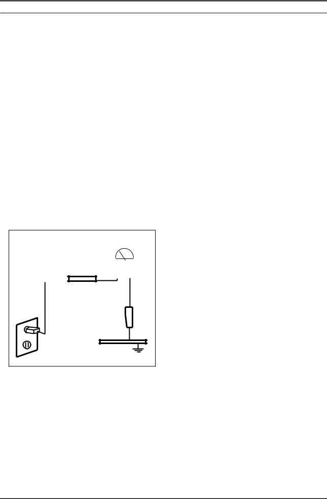
3.Leakage Current Hot Check (Figure 1-1):
WARNING : Do not use an isolation transformer during this test.
Use a leakage current tester or a metering system that complies with American National Standards Institute (ANSI C101.1, Leakage Current for Appliances), and Underwriters Laboratories (UL Publication UL1410, 59.7).
(READING SHOULD)
NOT BE ABOVE 0.5mA
|
|
|
|
|
|
|
|
|
|
LEAKAGE |
|
DEVICE |
|
|
|
||
|
|
|
CURRENT |
||
UNDER |
|
|
|
||
|
|
|
TESTER |
||
TEST |
|
|
|
||
|
|
|
|
|
|
|
TEST ALL |
|
|
|
|
|
|
|
|
||
|
EXPOSED METAL |
|
|
|
|
|
SURFACES |
|
|
|
|
2-WIRE CORD |
|
|
|
||
*ALSO TEST WITH |
|
|
PLUG REVERSED |
|
|
(USING AC ADAPTER |
|
|
PLUG AS REQUIRED) |
EARTH |
|
|
|
|
|
GROUND |
Figure 1-1. Leakage Current Test Circuit |
|
|
4.With the unit completely reassembled, plug the AC line cord directly into a 120V AC outlet. With the unit’s AC switch first in the ON position and then OFF, measure the current between a known earth ground (metal water pipe, conduit, etc.) and all exposed metal parts, including: metal cabinets, screwheads and control shafts.
The current measured should not exceed 0.5 milliamp.
Reverse the power-plug prongs in the AC outlet and repeat the test.
1-1-4. Product Safety Notices
Some electrical and mechanical parts have special safetyrelated characteristics which are often not evident from visual inspection. The protection they give may not be obtained by replacing them with components rated for higher voltage, wattage, etc. Parts that have special safety characteristics are identified by  on schematics and parts lists. A substitute replacement that does not have the same safety characteristics as the recommended replacement part might create shock, fire and/or other hazards. Product safety is under review continuously and new instructions are issued whenever appropriate.
1-1

1. Precautions
1-2. Servicing Precautions
WARNING: An electrolytic capacitor installed with the wrong polarity might explode.
Caution: Before servicing units covered by this service manual, read and follow the Safety Precautions section of this manual.
Note: If unforeseen circumstances create conflict between the following servicing precautions and any of the safety precautions, always follow the safety precautions.
1-2-1 General Servicing Precautions
1.Always unplug the unit’s AC power cord from the AC power source and disconnect the DC Power Jack before attempting to:
(a) remove or reinstall any component or assembly, (b) disconnect PCB plugs or connectors, (c) connect a test component in parallel with an electrolytic capacitor.
2.Some components are raised above the printed circuit board for safety. An insulation tube or tape is sometimes used. The internal wiring is sometimes clamped to prevent contact with thermally hot components. Reinstall all such elements to their original position.
3.After servicing, always check that the screws, components and wiring have been correctly reinstalled. Make sure that the area around the serviced part has not been damaged.
4.Check the insulation between the blades of the AC plug and accessible conductive parts (examples: metal panels, input terminals and earphone jacks).
5.Insulation Checking Procedure: Disconnect the power cord from the AC source and turn the power switch ON.
Connect an insulation resistance meter (500 V) to theblades of the AC plug.
The insulation resistance between each blade of the AC plug and accessible conductive parts (see above) should be greater than 1 megohm.
6.Always connect a test instrument’s ground lead to the instrument chassis ground before connecting the positive lead; always remove the instrument’s ground lead last.
1-3. Electrostatically Sensitive Devices (ESD) Precautions
Some semiconductor (solid state) devices can be easily damaged by static electricity. Such components are commonly called Electrostatically Sensitive Devices (ESD). Examples of typical ESD are integrated circuits and some field-effect transistors. The following techniques will reduce the incidence of component damage caused by static electricity.
1.Immediately before handling any semiconductor components or assemblies, drain the electrostatic charge from your body by touching a known earth ground. Alternatively, wear a discharging wrist-strap device. To avoid a shock hazard, be sure to remove the wrist strap before applying power to the LED/LCD TV.
2.After removing an ESD-equipped assembly, place it on a conductive surface such as aluminum foil to prevent accumulation of an electrostatic charge.
3.Do not use freon-propelled chemicals. These can generate electrical charges sufficient to damage ESDs.
4.Use only a grounded-tip soldering iron to solder or desolder ESDs.
5.Use only an anti-static solder removal device. Some solder removal devices not classified as “anti-static” can generate electrical charges sufficient to damage ESDs.
6.Do not remove a replacement ESD from its protective package until you are ready to install it. Most replacement ESDs are packaged with leads that are electrically shorted together by conductive foam, aluminum foil or other conductive materials.
7.Immediately before removing the protective material from the leads of a replacement ESD, touch the protective material to the chassis or circuit assembly into which the device will be installed.
Caution: Be sure no power is applied to the chassis or circuit and observe all other safety precautions.
8.Minimize body motions when handling unpackaged replacement ESDs. Motions such as brushing clothes together, or lifting your foot from a carpeted floor can generate enough static electricity to damage an ESD.
1-2

1. Precautions
1-4. Installation Precautions
1.For safety reasons, more than a people are required for carrying the product.
2.Keep the power cord away from any heat emitting devices, as a melted covering may cause fire or electric shock.
3.Do not place the product in areas with poor ventilation such as a bookshelf or closet. The increased internal temperature may cause fire.
4.Bend the external antenna cable when connecting it to the product. This is a measure to protect it from being exposed to moisture. Otherwise, it may cause a fire or electric shock.
5.Make sure to turn the power off and unplug the power cord from the outlet before repositioning the product. Also check the antenna cable or the external connectors if they are fully unplugged. Damage to the cord may cause fire or electric shock.
6.Keep the antenna far away from any high-voltage cables and install it firmly. Contact with the highvoltage cable or the antenna falling over may cause fire or electric shock.
7.When installing the product, leave enough space (0.4m) between the product and the wall for ventilation purposes.
A rise in temperature within the product may cause fire.
1-3

2. Product specifications
2. Product specifications
2-1. Feature & Specifications
Model |
|
|
UE22D5003BW |
|
|
|
|
|
|
|
Feature |
|
|
||
DTV/ATV, 2-HDMI, 1-SCART, 1-USB2.0 |
|
||
Brightness : 480 cd/m2 |
|
|
|
High Contrast Ratio : 6,000 :1 |
|
|
|
Response Time : 8.5 ms |
|
|
|
|
|
|
|
|
|
|
Specifications |
|
|
|
|
Item |
|
|
Description |
|
|
|
|
LCD Panel |
|
22 inch FHD |
|
|
|
|
|
Scanning Frequency |
|
Horizontal : 50 kHz ~ 75 kHz (Automatic) |
|
|
|
Vertical : 47 Hz ~ 63 Hz (Automatic) |
|
|
|
|
|
Display Colors |
|
16.7M color |
|
|
|
|
|
Maximum resolution |
|
Horizontal : 1920 Pixels |
|
|
|
Vertical : 1080 Pixels |
|
|
|
|
|
Input Signal |
|
Analog 0.7 Vp-p ± 5% positive at 75Ω , internally terminated |
|
|
|
|
|
Input Sync Signal |
|
H/V Separate, TTL, P. or N. |
|
|
|
|
|
Maximum Pixel Clock rate |
|
80 MHz |
|
|
|
|
|
Active Display |
|
|
|
Horizontal/Vertical |
|
476.64(H) x 268.11(V) mm |
|
|
|
|
|
AC power voltage & Frequency |
|
AC 110 V ~ 220 V, 60 Hz |
|
|
|
|
|
Power Consumption |
|
Under 110 W (Under 0.3 W, Stand by) |
|
|
|
|
|
Dimensions |
|
|
|
Set (W x D x H) |
|
515.8 x 124 x 350.0 mm_with stand |
|
|
|
515.8 x 39.9 x 315.6 mm_without stand |
|
|
|
|
|
Weight |
|
3.5 kg_with stand |
|
|
|
3.4 kg_without stand |
|
|
|
|
|
Stand Weight |
|
0.1 kg |
|
|
|
|
|
TV System |
|
Tuning |
Frequency Synthesize (Refer to detailed Frequency Table) |
|
|
|
|
|
|
System |
DVB-T/C, PAL, SECAM, NT4.43 |
|
|
|
|
|
|
Sound |
BG, DK, L/L’, NICAM, MPEG1, DD, DD+, HE-AAC |
|
|
|
|
Environmental Considerations |
|
Operating Temperature : 50˚F ~ 104˚F (10˚C ~ 40˚C) |
|
|
|
Operating Humidity : 10% ~ 80%, non-condensing |
|
|
|
Storage temperature : -13˚F ~ 113˚F (-25˚C ~ 45˚C) |
|
|
|
Storage Humidity : 5% ~ 95%, non-condensing |
|
|
|
|
|
Audio Spec. |
|
- MAX Internal Audio Output Power : Each 3 W (Left/Right) |
|
|
|
- BASS Control Range : -8 dB ~ + 8dB |
|
|
|
- TREBLE Control Range : -8 dB ~ +8 dB |
|
|
|
- Headphone Out : 10 mW MAX |
|
|
|
- Output Frequency : RF : 80 Hz ~ 15 kHz |
|
|
|
|
AV/Componet/HDMI : 80 Hz ~ 20 kHz |
|
|
|
|
2-1

2. Product specifications
Model |
UE40D5003BW |
|
|
Feature
DTV/ATV, 2-HDMI, 1-SCART, 1-USB2.0
Brightness : 480 cd/m2
High Contrast Ratio : 6,000 :1Response Time : 8.5 ms
|
|
Specifications |
|
|
|
Item |
|
Description |
|
|
|
LCD Panel |
40 inch FHD |
|
|
|
|
Scanning Frequency |
Horizontal : 50 kHz ~ 75 kHz (Automatic) |
|
|
Vertical : 47 Hz ~ 63 Hz (Automatic) |
|
|
|
|
Display Colors |
16.7M color |
|
|
|
|
Maximum resolution |
Horizontal : 1920 Pixels |
|
|
Vertical : 1080 Pixels |
|
|
|
|
Input Signal |
Analog 0.7 Vp-p ± 5% positive at 75Ω , internally terminated |
|
|
|
|
Input Sync Signal |
H/V Separate, TTL, P. or N. |
|
|
|
|
Maximum Pixel Clock rate |
80 MHz |
|
|
|
|
Active Display |
|
|
Horizontal/Vertical |
885.6(H) x 498.15(V) mm |
|
|
|
|
AC power voltage & Frequency |
AC 110 V ~ 220 V, 60 Hz |
|
|
|
|
Power Consumption |
Under 110 W (Under 0.3 W, Stand by) |
|
|
|
|
Dimensions |
|
|
Set (W x D x H) |
943.8 x 219.4 x 603.5 mm_with stand |
|
|
943.8 x 51.0 x 561.4 mm_without stand |
|
|
|
|
Weight |
11 kg_with stand |
|
|
10.6 kg_without stand |
|
|
|
|
Stand Weight |
0.4 kg |
|
|
|
|
TV System |
Tuning |
Frequency Synthesize (Refer to detailed Frequency Table) |
|
|
|
|
System |
DVB-T/C, PAL, SECAM, NT4.43 |
|
|
|
|
Sound |
BG, DK, L/L’, NICAM, MPEG1, DD, DD+, HE-AAC |
|
|
|
Environmental Considerations |
Operating Temperature : 50˚F ~ 104˚F (10˚C ~ 40˚C) |
|
|
Operating Humidity : 10% ~ 80%, non-condensing |
|
|
Storage temperature : -13˚F ~ 113˚F (-25˚C ~ 45˚C) |
|
|
Storage Humidity : 5% ~ 95%, non-condensing |
|
|
|
|
Audio Spec. |
- MAX Internal Audio Output Power : Each 3 W (Left/Right) |
|
|
- BASS Control Range : -8 dB ~ + 8dB |
|
|
- TREBLE Control Range : -8 dB ~ +8 dB |
|
|
- Headphone Out : 10 mW MAX |
|
|
- Output Frequency : RF : 80 Hz ~ 15 kHz |
|
|
|
AV/Componet/HDMI : 80 Hz ~ 20 kHz |
|
|
|
2-2

2. Product specifications
Model |
UE19D4003BW |
|
|
Feature
DTV/ATV, 2-HDMI, 1-SCART, 1-USB2.0
Brightness : 480 cd/m2
High Contrast Ratio : 6,000 :1Response Time : 8.5 ms
|
|
Specifications |
|
|
|
Item |
|
Description |
|
|
|
LCD Panel |
19 inch HD |
|
|
|
|
Scanning Frequency |
Horizontal : 50 kHz ~ 75 kHz (Automatic) |
|
|
Vertical : 47 Hz ~ 63 Hz (Automatic) |
|
|
|
|
Display Colors |
16.7M color |
|
|
|
|
Maximum resolution |
Horizontal : 1920 Pixels |
|
|
Vertical : 1080 Pixels |
|
|
|
|
Input Signal |
Analog 0.7 Vp-p ± 5% positive at 75Ω , internally terminated |
|
|
|
|
Input Sync Signal |
H/V Separate, TTL, P. or N. |
|
|
|
|
Maximum Pixel Clock rate |
80 MHz |
|
|
|
|
Active Display |
|
|
Horizontal/Vertical |
409.8(H) x 230.4(V) mm |
|
|
|
|
AC power voltage & Frequency |
AC 110 V ~ 220 V, 60 Hz |
|
|
|
|
Power Consumption |
Under 110 W (Under 0.3 W, Stand by) |
|
|
|
|
Dimensions |
|
|
Set (W x D x H) |
447.2 x 124 x 312.4 mm_with stand |
|
|
447.2 x 39.9 x 277.8 mm_without stand |
|
|
|
|
Weight |
2.9 kg_with stand |
|
|
2.8 kg_without stand |
|
|
|
|
Stand Weight |
0.1 kg |
|
|
|
|
TV System |
Tuning |
Frequency Synthesize (Refer to detailed Frequency Table) |
|
|
|
|
System |
DVB-T/C, PAL, SECAM, NT4.43 |
|
|
|
|
Sound |
BG, DK, L/L’, NICAM, MPEG1, DD, DD+, HE-AAC |
|
|
|
Environmental Considerations |
Operating Temperature : 50˚F ~ 104˚F (10˚C ~ 40˚C) |
|
|
Operating Humidity : 10% ~ 80%, non-condensing |
|
|
Storage temperature : -13˚F ~ 113˚F (-25˚C ~ 45˚C) |
|
|
Storage Humidity : 5% ~ 95%, non-condensing |
|
|
|
|
Audio Spec. |
- MAX Internal Audio Output Power : Each 3 W (Left/Right) |
|
|
- BASS Control Range : -8 dB ~ + 8dB |
|
|
- TREBLE Control Range : -8 dB ~ +8 dB |
|
|
- Headphone Out : 10 mW MAX |
|
|
- Output Frequency : RF : 80 Hz ~ 15 kHz |
|
|
|
AV/Componet/HDMI : 80 Hz ~ 20 kHz |
|
|
|
2-3

2. Product specifications
Model |
UE26D4003BW |
|
|
Feature
DTV/ATV, 2-HDMI, 1-SCART, 1-USB2.0
Brightness : 480 cd/m2
High Contrast Ratio : 6,000 :1Response Time : 8.5 ms
|
|
Specifications |
|
|
|
Item |
|
Description |
|
|
|
LCD Panel |
26 inch HD |
|
|
|
|
Scanning Frequency |
Horizontal : 50 kHz ~ 75 kHz (Automatic) |
|
|
Vertical : 47 Hz ~ 63 Hz (Automatic) |
|
|
|
|
Display Colors |
16.7M color |
|
|
|
|
Maximum resolution |
Horizontal : 1920 Pixels |
|
|
Vertical : 1080 Pixels |
|
|
|
|
Input Signal |
Analog 0.7 Vp-p ± 5% positive at 75Ω , internally terminated |
|
|
|
|
Input Sync Signal |
H/V Separate, TTL, P. or N. |
|
|
|
|
Maximum Pixel Clock rate |
80 MHz |
|
|
|
|
Active Display |
|
|
Horizontal/Vertical |
575.679(H) x 323.721(V) mm |
|
|
|
|
AC power voltage & Frequency |
AC 110 V ~ 220 V, 60 Hz |
|
|
|
|
Power Consumption |
Under 110 W (Under 0.3 W, Stand by) |
|
|
|
|
Dimensions |
|
|
Set (W x D x H) |
624.0 x 169.4 x 418.3 mm_with stand |
|
|
624.0 x 45.1 x 377.2 mm_without stand |
|
|
|
|
Weight |
4.4 kg_with stand |
|
|
4.1 kg_without stand |
|
|
|
|
Stand Weight |
0.3 kg |
|
|
|
|
TV System |
Tuning |
Frequency Synthesize (Refer to detailed Frequency Table) |
|
|
|
|
System |
DVB-T/C, PAL, SECAM, NT4.43 |
|
|
|
|
Sound |
BG, DK, L/L’, NICAM, MPEG1, DD, DD+, HE-AAC |
|
|
|
Environmental Considerations |
Operating Temperature : 50˚F ~ 104˚F (10˚C ~ 40˚C) |
|
|
Operating Humidity : 10% ~ 80%, non-condensing |
|
|
Storage temperature : -13˚F ~ 113˚F (-25˚C ~ 45˚C) |
|
|
Storage Humidity : 5% ~ 95%, non-condensing |
|
|
|
|
Audio Spec. |
- MAX Internal Audio Output Power : Each 3 W (Left/Right) |
|
|
- BASS Control Range : -8 dB ~ + 8dB |
|
|
- TREBLE Control Range : -8 dB ~ +8 dB |
|
|
- Headphone Out : 10 mW MAX |
|
|
- Output Frequency : RF : 80 Hz ~ 15 kHz |
|
|
|
AV/Componet/HDMI : 80 Hz ~ 20 kHz |
|
|
|
2-4
2. Product specifications
Model |
UE32D4003BW |
|
|
Feature
DTV/ATV, 2-HDMI, 1-SCART, 1-USB2.0
Brightness : 480 cd/m2
High Contrast Ratio : 6,000 :1Response Time : 8.5 ms
|
|
Specifications |
|
|
|
Item |
|
Description |
|
|
|
LCD Panel |
32 inch HD |
|
|
|
|
Scanning Frequency |
Horizontal : 50 kHz ~ 75 kHz (Automatic) |
|
|
Vertical : 47 Hz ~ 63 Hz (Automatic) |
|
|
|
|
Display Colors |
16.7M color |
|
|
|
|
Maximum resolution |
Horizontal : 1920 Pixels |
|
|
Vertical : 1080 Pixels |
|
|
|
|
Input Signal |
Analog 0.7 Vp-p ± 5% positive at 75Ω , internally terminated |
|
|
|
|
Input Sync Signal |
H/V Separate, TTL, P. or N. |
|
|
|
|
Maximum Pixel Clock rate |
80 MHz |
|
|
|
|
Active Display |
|
|
Horizontal/Vertical |
679.6845(H) x 392.256(V) mm |
|
|
|
|
AC power voltage & Frequency |
AC 110 V ~ 220 V, 60 Hz |
|
|
|
|
Power Consumption |
Under 110 W (Under 0.3 W, Stand by) |
|
|
|
|
Dimensions |
|
|
Set (W x D x H) |
756.4 x 182.4 x 498.1 mm_with stand |
|
|
756.4 x 47.8 x 454.0 mm_without stand |
|
|
|
|
Weight |
7.2 kg_with stand |
|
|
6.3 kg_without stand |
|
|
|
|
Stand Weight |
0.9 kg |
|
|
|
|
TV System |
Tuning |
Frequency Synthesize (Refer to detailed Frequency Table) |
|
|
|
|
System |
DVB-T/C, PAL, SECAM, NT4.43 |
|
|
|
|
Sound |
BG, DK, L/L’, NICAM, MPEG1, DD, DD+, HE-AAC |
|
|
|
Environmental Considerations |
Operating Temperature : 50˚F ~ 104˚F (10˚C ~ 40˚C) |
|
|
Operating Humidity : 10% ~ 80%, non-condensing |
|
|
Storage temperature : -13˚F ~ 113˚F (-25˚C ~ 45˚C) |
|
|
Storage Humidity : 5% ~ 95%, non-condensing |
|
|
|
|
Audio Spec. |
- MAX Internal Audio Output Power : Each 3 W (Left/Right) |
|
|
- BASS Control Range : -8 dB ~ + 8dB |
|
|
- TREBLE Control Range : -8 dB ~ +8 dB |
|
|
- Headphone Out : 10 mW MAX |
|
|
- Output Frequency : RF : 80 Hz ~ 15 kHz |
|
|
|
AV/Componet/HDMI : 80 Hz ~ 20 kHz |
|
|
|
2-5

2. Product specifications
Model |
LE40D503F7W |
|
|
Feature
DTV/ATV, 2-HDMI, 1-SCART, 1-USB2.0
Brightness : 480 cd/m2
High Contrast Ratio : 6,000 :1Response Time : 8.5 ms
|
|
Specifications |
|
|
|
Item |
|
Description |
|
|
|
LCD Panel |
40 inch HD |
|
|
|
|
Scanning Frequency |
Horizontal : 50 kHz ~ 75 kHz (Automatic) |
|
|
Vertical : 47 Hz ~ 63 Hz (Automatic) |
|
|
|
|
Display Colors |
16.7M color |
|
|
|
|
Maximum resolution |
Horizontal : 1920 Pixels |
|
|
Vertical : 1080 Pixels |
|
|
|
|
Input Signal |
Analog 0.7 Vp-p ± 5% positive at 75Ω , internally terminated |
|
|
|
|
Input Sync Signal |
H/V Separate, TTL, P. or N. |
|
|
|
|
Maximum Pixel Clock rate |
80 MHz |
|
|
|
|
Active Display |
|
|
Horizontal/Vertical |
575.679(H) x 323.721(V) mm |
|
|
|
|
AC power voltage & Frequency |
AC 110 V ~ 220 V, 60 Hz |
|
|
|
|
Power Consumption |
Under 110 W (Under 0.3 W, Stand by) |
|
|
|
|
Dimensions |
|
|
Set (W x D x H) |
967.0 x 199.9 x 626.1 mm_with stand |
|
|
967.0 x 107.1 x 586.3 mm_without stand |
|
|
|
|
Weight |
13.25 kg_with stand |
|
|
11.6 kg_without stand |
|
|
|
|
Stand Weight |
1.65 kg |
|
|
|
|
TV System |
Tuning |
Frequency Synthesize (Refer to detailed Frequency Table) |
|
|
|
|
System |
DVB-T/C, PAL, SECAM, NT4.43 |
|
|
|
|
Sound |
BG, DK, L/L’, NICAM, MPEG1, DD, DD+, HE-AAC |
|
|
|
Environmental Considerations |
Operating Temperature : 50˚F ~ 104˚F (10˚C ~ 40˚C) |
|
|
Operating Humidity : 10% ~ 80%, non-condensing |
|
|
Storage temperature : -13˚F ~ 113˚F (-25˚C ~ 45˚C) |
|
|
Storage Humidity : 5% ~ 95%, non-condensing |
|
|
|
|
Audio Spec. |
- MAX Internal Audio Output Power : Each 3 W (Left/Right) |
|
|
- BASS Control Range : -8 dB ~ + 8dB |
|
|
- TREBLE Control Range : -8 dB ~ +8 dB |
|
|
- Headphone Out : 10 mW MAX |
|
|
- Output Frequency : RF : 80 Hz ~ 15 kHz |
|
|
|
AV/Componet/HDMI : 80 Hz ~ 20 kHz |
|
|
|
2-6

2. Product specifications
Model |
LE32D403E2W |
|
|
Feature
DTV/ATV, 2-HDMI, 1-SCART, 1-USB2.0
Brightness : 480 cd/m2
High Contrast Ratio : 6,000 :1Response Time : 8.5 ms
|
|
Specifications |
|
|
|
Item |
|
Description |
|
|
|
LCD Panel |
32 inch HD |
|
|
|
|
Scanning Frequency |
Horizontal : 50 kHz ~ 75 kHz (Automatic) |
|
|
Vertical : 47 Hz ~ 63 Hz (Automatic) |
|
|
|
|
Display Colors |
16.7M color |
|
|
|
|
Maximum resolution |
Horizontal : 1920 Pixels |
|
|
Vertical : 1080 Pixels |
|
|
|
|
Input Signal |
Analog 0.7 Vp-p ± 5% positive at 75Ω , internally terminated |
|
|
|
|
Input Sync Signal |
H/V Separate, TTL, P. or N. |
|
|
|
|
Maximum Pixel Clock rate |
80 MHz |
|
|
|
|
Active Display |
|
|
Horizontal/Vertical |
697.6(H) x 392.2(V) mm |
|
|
|
|
AC power voltage & Frequency |
AC 110 V ~ 220 V, 60 Hz |
|
|
|
|
Power Consumption |
Under 110 W (Under 0.3 W, Stand by) |
|
|
|
|
Dimensions |
|
|
Set (W x D x H) |
784.4 x 181.9 x 542.3 mm_with stand |
|
|
784.4 x 103.3 x 502.9 mm_without stand |
|
|
|
|
Weight |
8.66 kg_with stand |
|
|
7.65 kg_without stand |
|
|
|
|
Stand Weight |
1.01 kg |
|
|
|
|
TV System |
Tuning |
Frequency Synthesize (Refer to detailed Frequency Table) |
|
|
|
|
System |
DVB-T/C, PAL, SECAM, NT4.43 |
|
|
|
|
Sound |
BG, DK, L/L’, NICAM, MPEG1, DD, DD+, HE-AAC |
|
|
|
Environmental Considerations |
Operating Temperature : 50˚F ~ 104˚F (10˚C ~ 40˚C) |
|
|
Operating Humidity : 10% ~ 80%, non-condensing |
|
|
Storage temperature : -13˚F ~ 113˚F (-25˚C ~ 45˚C) |
|
|
Storage Humidity : 5% ~ 95%, non-condensing |
|
|
|
|
Audio Spec. |
- MAX Internal Audio Output Power : Each 3 W (Left/Right) |
|
|
- BASS Control Range : -8 dB ~ + 8dB |
|
|
- TREBLE Control Range : -8 dB ~ +8 dB |
|
|
- Headphone Out : 10 mW MAX |
|
|
- Output Frequency : RF : 80 Hz ~ 15 kHz |
|
|
|
AV/Componet/HDMI : 80 Hz ~ 20 kHz |
|
|
|
2-7

2. Product specifications
Model |
LE32D400E1W |
|
|
Feature
DTV/ATV, 2-HDMI, 1-SCART, 1-USB2.0
Brightness : 480 cd/m2
High Contrast Ratio : 6,000 :1Response Time : 8.5 ms
|
|
Specifications |
|
|
|
Item |
|
Description |
|
|
|
LCD Panel |
32 inch HD |
|
|
|
|
Scanning Frequency |
Horizontal : 50 kHz ~ 75 kHz (Automatic) |
|
|
Vertical : 47 Hz ~ 63 Hz (Automatic) |
|
|
|
|
Display Colors |
16.7M color |
|
|
|
|
Maximum resolution |
Horizontal : 1920 Pixels |
|
|
Vertical : 1080 Pixels |
|
|
|
|
Input Signal |
Analog 0.7 Vp-p ± 5% positive at 75Ω , internally terminated |
|
|
|
|
Input Sync Signal |
H/V Separate, TTL, P. or N. |
|
|
|
|
Maximum Pixel Clock rate |
80 MHz |
|
|
|
|
Active Display |
|
|
Horizontal/Vertical |
697.6(H) x 392.2(V) mm |
|
|
|
|
AC power voltage & Frequency |
AC 110 V ~ 220 V, 60 Hz |
|
|
|
|
Power Consumption |
Under 110 W (Under 0.3 W, Stand by) |
|
|
|
|
Dimensions |
|
|
Set (W x D x H) |
784.4 x 181.9 x 542.3 mm_with stand |
|
|
784.4 x 103.3 x 502.9 mm_without stand |
|
|
|
|
Weight |
9.2 kg_with stand |
|
|
8.1 kg_without stand |
|
|
|
|
Stand Weight |
1.1 kg |
|
|
|
|
TV System |
Tuning |
Frequency Synthesize (Refer to detailed Frequency Table) |
|
|
|
|
System |
DVB-T/C, PAL, SECAM, NT4.43 |
|
|
|
|
Sound |
BG, DK, L/L’, NICAM, MPEG1, DD, DD+, HE-AAC |
|
|
|
Environmental Considerations |
Operating Temperature : 50˚F ~ 104˚F (10˚C ~ 40˚C) |
|
|
Operating Humidity : 10% ~ 80%, non-condensing |
|
|
Storage temperature : -13˚F ~ 113˚F (-25˚C ~ 45˚C) |
|
|
Storage Humidity : 5% ~ 95%, non-condensing |
|
|
|
|
Audio Spec. |
- MAX Internal Audio Output Power : Each 3 W (Left/Right) |
|
|
- BASS Control Range : -8 dB ~ + 8dB |
|
|
- TREBLE Control Range : -8 dB ~ +8 dB |
|
|
- Headphone Out : 10 mW MAX |
|
|
- Output Frequency : RF : 80 Hz ~ 15 kHz |
|
|
|
AV/Componet/HDMI : 80 Hz ~ 20 kHz |
|
|
|
2-8
2. Product specifications
2-2. Detail Factory Option
If you replace the main board with new one, please change the factory option as well. The options you must change are "Type" and "Front Color".
2-2-1. UD5003 / UD4003
Model Name |
|
UE22D5003BW |
UE40D5003BW |
UE19D4003BW |
UE26D4003BW |
UE32D4003BW |
|
|
|
|
|
|
|
|
|
|
|
Vendor |
AML |
CHILIN(CMI) |
AML |
CHILIN(CMI) |
CHLIN(CMI) |
Panel |
|
|
|
|
|
|
|
|
CODE |
BN07-01044A |
BN07-00990B |
BN07-01043A |
BN07-01049A |
BN07-00988D |
|
|
|
|
|
|
|
|
|
|
|
SPEC |
LTM215HT04-V |
LD400BGC-C2 |
LTM185AT05-V |
LD260AGC-C1 |
LD320AGC-C4 |
|
|
|
|
|
|
|
|
|
|
Vendor |
POWER |
SEC |
POWER |
SEC |
SEC |
SMPS |
|
|
|
|
|
|
|
|
CODE |
BN44-00467A |
BN44-00473A |
BN44-00467A |
BN44-00471A |
BN44-00472A |
|
|
|
|
|
|
|
|
|
|
|
SPEC |
PD22A0_BPNV |
PD46G0_BSM |
PD22A0_BPNV |
PD26G0S_BSM |
PD32G0S_BSM |
|
|
|
|
|
|
|
|
1Factory Reset
2Type
3 |
Local set |
EU |
EU |
EU |
EU |
EU |
|
|
|
|
|
|
|
4 |
Model |
UD5003 |
UD5003 |
UD4003 |
UD4003 |
UD4003 |
|
|
|
|
|
|
|
5 |
TUNER |
SEC_TC |
SEC_TC |
SEC_TC |
SEC_TC |
SEC_TC |
6Ch Table
7Front Color
2-2-2. LD503/LD403/LD400
Model Name |
|
LE40D503F7W |
LE32D403E2W |
LE32D400E1W |
|
|
|
|
|
|
|
|
|
Vendor |
AML |
SHARP |
AML |
Panel |
|
|
|
|
|
|
CODE |
BN07-01052A |
BN07-01050A |
BN07-00978A |
|
|
|
|
|
|
|
|
|
SPEC |
LTF400HM05 |
CD320AGD-T1 |
LTF320AP11 |
|
|
|
|
|
|
|
|
Vendor |
HANSOL |
SEC |
SEC |
SMPS |
|
|
|
|
|
|
CODE |
BN44-00469B |
BN44-00468A |
BN44-00438A |
|
|
|
|
|
|
|
|
|
SPEC |
IV40F1_BHS |
PSIV121411C |
PSIV121411A |
|
|
|
|
|
|
1Factory Reset
2Type
3 |
Local set |
EU |
EU |
EU |
|
|
|
|
|
4 |
Model |
LD503 |
LD403 |
LD400 |
|
|
|
|
|
5 |
TUNER |
SEC_TC |
SEC_TC |
SEC_TC |
6Ch Table
7Front Color
2-9
2. Product specifications
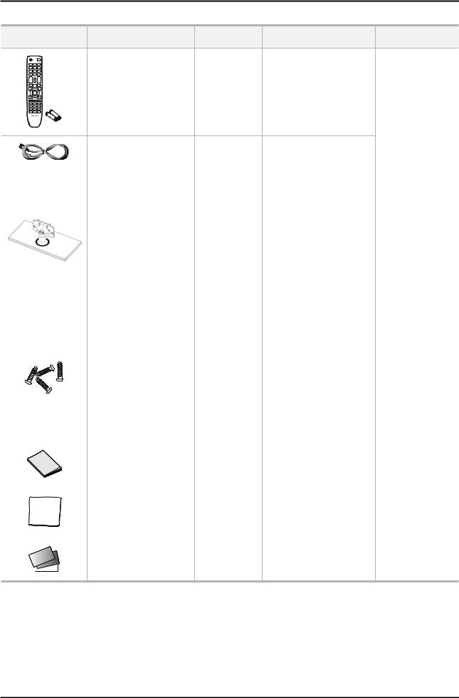
2-3. Accessories
Product |
Description |
Mode |
Code. No |
Remark |
Remote Control & Batteries |
ALL |
AA59-00496A |
|
(AAA x 2) |
4301-000121 |
||
|
|
Power Cord |
ALL |
3903-000525 |
|
|
|
|
|
|
|
|
5003 |
22" : BN90-03532B |
|
|
|
40" : BN90-03523C |
|
|
|
|
|
|
|
|
|
|
|
|
|
|
|
19" : BN90-03532B |
|
|
|
4003 |
26" : BN90-03524C |
|
|
Stand |
|
32" : BN90-03522C |
|
|
|
|
|
|
|
|
503 |
40" : BN90-03541B |
|
|
|
|
|
|
|
|
403 |
32" : BN90-03540B |
|
|
|
|
|
|
|
|
400 |
32" : BN90-03549A |
Samsung Electronics |
|
|
|
|
|
|
|
|
22" : 6003-001782 |
Service center |
|
|
|
|
|
|
|
5003 |
40" : 6002-001294 |
|
|
|
|
6001-002621 |
|
|
|
|
|
|
|
Screw |
4003 |
19" : 6003-001782 |
|
|
6001-002621 : M4 x L8 |
26" : 6002-001294 |
|
|
|
6003-001782 : M4 x L12 |
|
32" : 6001-002621 |
|
|
|
|
|
|
|
|
|
|
|
|
|
503 |
40" : 6002-001294 |
|
|
|
|
|
|
|
|
400/403 |
32" : 6002-001294 |
|
|
|
|
|
|
|
|
5003/4003 |
BN68-03713A |
|
|
Quick Start Guide |
|
|
|
503/403/400 |
BN68-03717A |
|
||
|
|
|
||
|
|
|
|
|
|
Cleaning Cloth |
ALL |
BN63-01798B |
|
|
|
|
|
|
|
Warranty Card / Registration |
|
BN68-00514K |
|
|
Card / Safety Guide Manual |
ALL |
|
|
|
BN68-03019A |
|
||
|
(Not available in all locations) |
|
|
|
|
|
|
|
2-10
2. Product specifications
2-4. New Features explanation
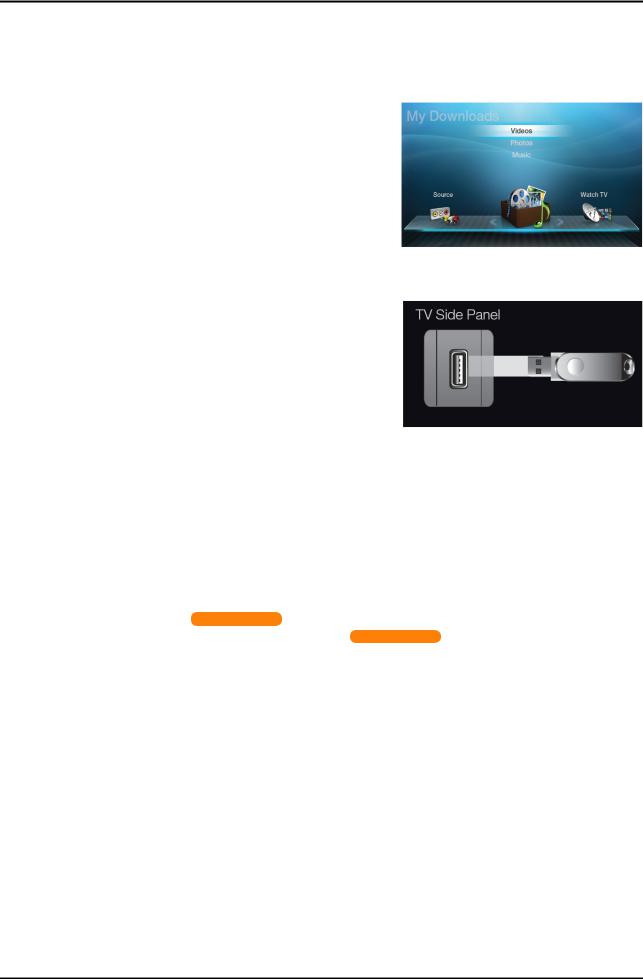
2-4-1. My Contents
Using the My Contents
Enjoy photos, music and/or movie files saved on a USB Mass Storage Class (MSC) device and/or your PC.
1.Press the CONTENT button to select My Contents.
2.Press u/dbutton to select desired menu (Videos, Photos, Music), then press the ENTEREbutton.
* It may differ depending on the model.
Connecting a USB Device
1.Turn on your TV.
2.Connect a USB device containing photo, music and/or movie files to the USB jack on the side of the TV.
3.When USB is connected to the TV, popup window appears. Then you can select Connected Device.
* It may differ depending on the model.
N It might not work properly with unlicensed multimedia files.
NNeed-to-Know List before using My Contents.
•MTP (Media Transfer Protocol) is not supported.
•The file system supports FAT16, FAT32 and NTFS.
•Certain types of USB Digital camera and audio devices may not be compatible with this TV.
•My Contents only supports USB Mass Storage Class (MSC) devices. MSC is a Mass Storage Class Bulk-Only Transport device. Examples of MSC are Thumb drives, Flash Card Readers and USB HDD (USB HUB are not supported). Devices should be connected directly to the TV’s USB port.
•Before connecting your device to the TV, please back up your files to prevent them from damage or loss of data. SAMSUNG is not responsible for any data file damage or data loss.
•USB (HDD) is not supported. for LED 4000 series
•Connect a USB HDD to the dedicated port, USB 1 (HDD) port. for LED 5000 series
•Do not disconnect the USB device while it is loading.
•The higher the resolution of the image, the longer it takes to display on the screen.
•The maximum supported JPEG resolution is 15360X8640 pixels.
•For unsupported or corrupted files, the “Not Supported File Format” message is displayed.
•If the files are sorted by Basic View, up to 1000 files can be displayed in each folder.
•MP3 files with DRM that have been downloaded from a non-free site cannot be played. Digital Rights Management (DRM) is a technology that supports the creation, distribution and management of the content in an integrated and comprehensive way, including the protection of the rights and interests of the content providers, the prevention of the illegal copying of contents, as well as managing billings and settlements.
•If more than 2 PTP devices are connected, you can only use one at a time.
•If more than two MSC devices are connected, some of them may not be recognized. A USB device that requires high power (more than 500mA or 5V) may not be supported. If an over-power warning message is displayed while you are connecting or using a USB device, the device may not be recognized or may malfunction.
•If the TV has been no input during time set in Auto Protection Time, the Screensaver will run.
•The power-saving mode of some external hard disk drives may be released automatically when connected to the TV.
•If a USB extension cable is used, the USB device may not be recognized or the files on the device may not be read.
•If a USB device connected to the TV is not recognized, the list of files on the device is corrupted or a file in the list is not played, connect the USB device to the PC, format the device and check the connection.
•If a file deleted from the PC is still found when My Contents is run, use the “Empty the Recycle Bin” function on the PC to permanently delete the file.
2-11
2. Product specifications
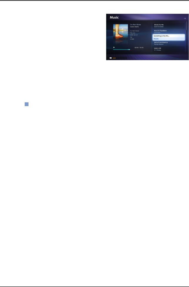
Music
01. Playing Music
1.Press the ◄/►/▲/▼ button to select the desired Music in the file list.
2.Press the ENTERE button or (Play) button.
–You can use (REW) and μ(FF) buttons during playback.
NOnly displays the files with MP3 and PCM file extension. Other file extensions are not displayed, even if they are saved on the same USB device.
NIf the sound is abnormal when playing MP3 files, adjust the Equalizer in the Sound menu. (An over-modulated MP3 file may cause a sound problem.)
02.Playing selected music
1.Press the C (Edit Mode) button.
2.Select the desired music.
–The check box appears to the left of the selected files.
3.Press the TOOLS button and select Play Selected Contents.
–You can select or deselect all music pressing the Select All/Deselect All.
2-12

2. Product specifications
Photos
01. Viewing a Photo (or Slide Show)
1.Press the ◄/►/▲/▼ button to select the desired Music in the file list.
2.Press the ENTERE button or (Play) button.
–When a selected photo is displayed, press the ENTERE button to start the slide show.
–During the slide show, all files in the file list will be displayed in order.
N When you press the (Play) button in the file list, slide show will be started immediately.
N Music files can be automatically played during the Slide Show if the Background Music is set to On. N The BGM Mode cannot be changed until the BGM has finished loading.
2-13

2. Product specifications
2-4-2. e-Manual
How to view the e-Manual
2-14
2. Product specifications
2-15
3. Disassembly and Reassembly
3. Disassembly and Reassembly
This section of the service manual describes the disassembly and reassembly procedures for the LED/LCD TV.
 WARNING: This LED/LCD TV contains electrostatically sensitive devices. Use caution when handling these components.
3-1. Disassembly and Reassembly
Cautions: 1. |
Disconnect the LED/LCD TV from the power source before disassembly. |
|
|
2. |
Follow these directions carefully; never use metal instruments to pry apart the cabinet. |
|
|
LE32D400 |
|
|
|
|
|
|
|
|
Description |
Picture Description |
Screws |
|
|
|
|
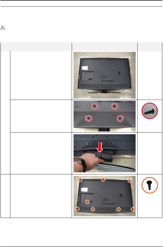
1 Place the TV face down on cushioned table. |
|
|
|
Remove 4 screws from the Stand.
6003-001785
Remove Stand.
2 |
Remove the screws of Rear-Cover. |
• 32D400/32D403/32D503 : |
|
|
Remove the 8 screws. |
6003-001782
3-1
3. Disassembly and Reassembly
Description |
Picture Description |
Screws |
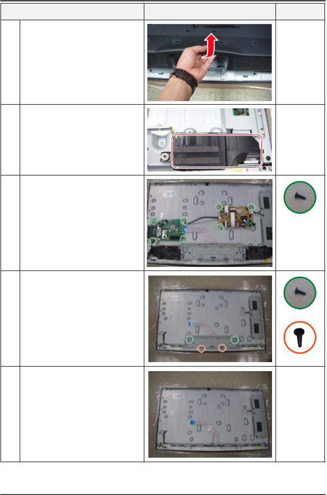
3 Lift up the Rear-Cover.
4 Remove the left and right speaker.
5 |
Remove the 4 screws of Main Board. |
Remove the 5 screws of SMPS Board. |
6003-001782
6 |
Remove the 6 screws of Bracket Stand Link & |
Guide. (Machine type : 4 EA) |
6003-001782
7 Remove the Stand Link.
3-2
3. Disassembly and Reassembly
Description |
Picture Description |
Screws |
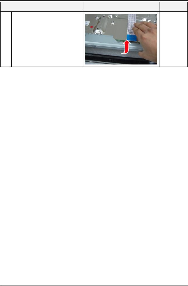
8 Lift up the Panel.
Reassembly procedures are in the reverse order of disassembly procedures.
3-3
3. Disassembly and Reassembly
UE32D4003
Description |
Picture Description |
Screws |
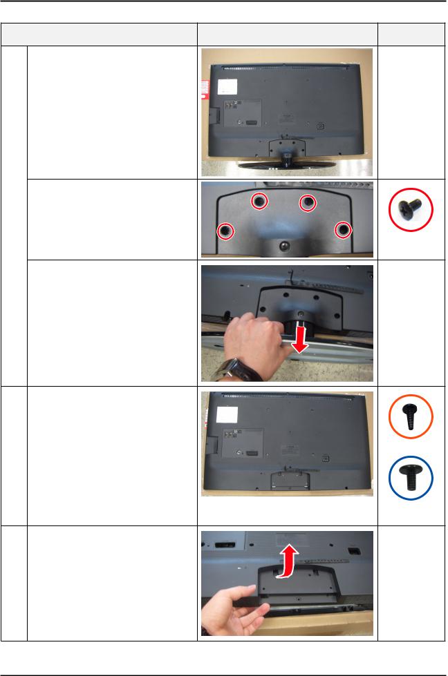
1 Place the TV face down on cushioned table.
Remove 4 screws from the Stand.(machine type)
6001-002621 (Machine)
Remove Stand.
2 |
Remove the screws of Rear-Cover. |
|
• 26D4003 |
: Remove the 4 screws. |
|
|
• 32D4003 |
: Remove the 10 screws. |
|
|
(machine type : 1 EA) |
|
• 40D5003 |
: Remove the 11 screws. |
|
|
(machine type : 3 EA) |
6001-002671 (Machine)
3 Lift up the Rear-Cover.
3-4
3. Disassembly and Reassembly
Description |
Picture Description |
Screws |
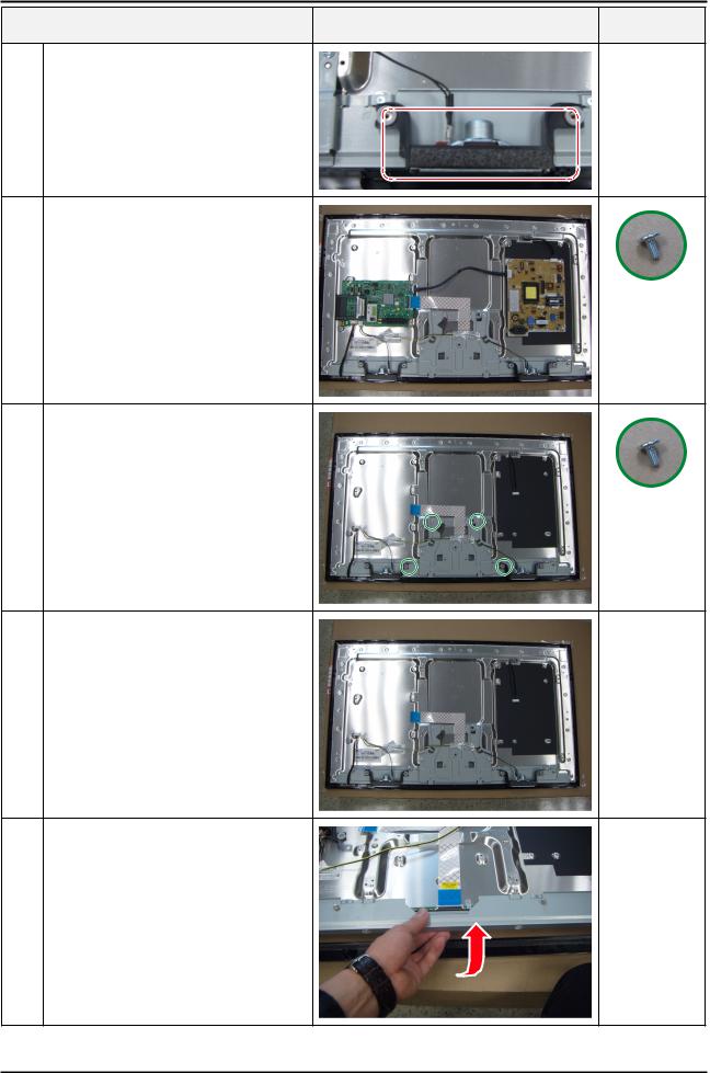
4 Remove the left and right speaker.
5 |
Remove the 4 screws of Main Board. |
Remove the 5 screws of SMPS Board. |
6001-002653
(Machine)
6 Remove the 4 screws of Bracket Stand Link
6001-002653
(Machine)
7 Remove the Stand Link.
8 Lift up the Panel.
Reassembly procedures are in the reverse order of disassembly procedures.
3-5
3. Disassembly and Reassembly
UE22D5003
|
Description |
Picture Description |
Screws |
|
|
|
|
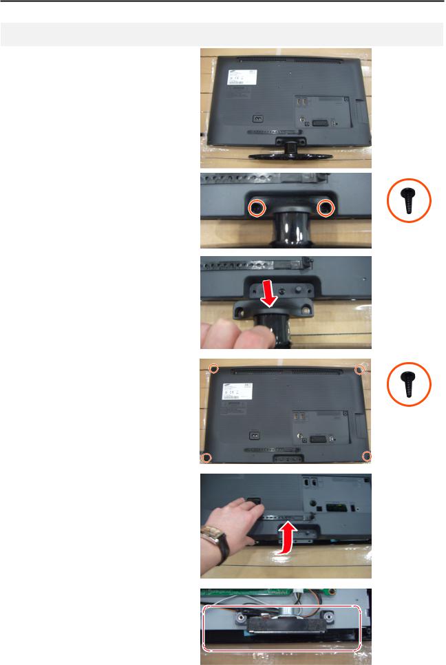
1 |
Place the TV face down on cushioned table. |
|
|
|
|
|
|
|
Remove 2 screws from the stand. |
|
|
|
(machine type) |
|
|
|
|
|
6003-001782 |
|
|
|
|
|
Remove Stand. |
|
|
|
|
|
|
2 |
Remove the screws of Rear-Cover. |
|
|
• 19D4003/22D5003 : Remove the 4 screws. |
|
|
|
|
|
|
6003-001782 |
|
|
|
|
3 |
Lift up the Rear-Cover. |
|
|
|
|
|
|
4 |
Remove the left and right speaker. |
|
|
|
|
|
|
|
|
|
|
3-6
3. Disassembly and Reassembly
|
Description |
Picture Description |
Screws |
|
|
|
|
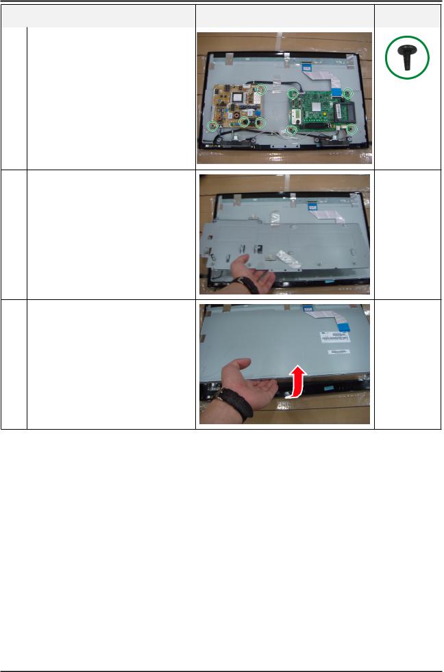
5 |
Remove the 4 screws of Main Board. |
|
|
Remove the 3 screws of SMPS Board. |
|
|
6003-000115
6 Remove the Stand Link.
7 Lift up the Panel.
Reassembly procedures are in the reverse order of disassembly procedures.
3-7
4. Troubleshooting
4. Troubleshooting
4-1. Troubleshooting
4-1-1. Previous check
1.Check the various cable connections first.
•Check to see if any cables are damaged or burnt.
•Check to see if there is a disconnected or loose cable connection.
•Check to see if the cables are connected according to the connection diagram.
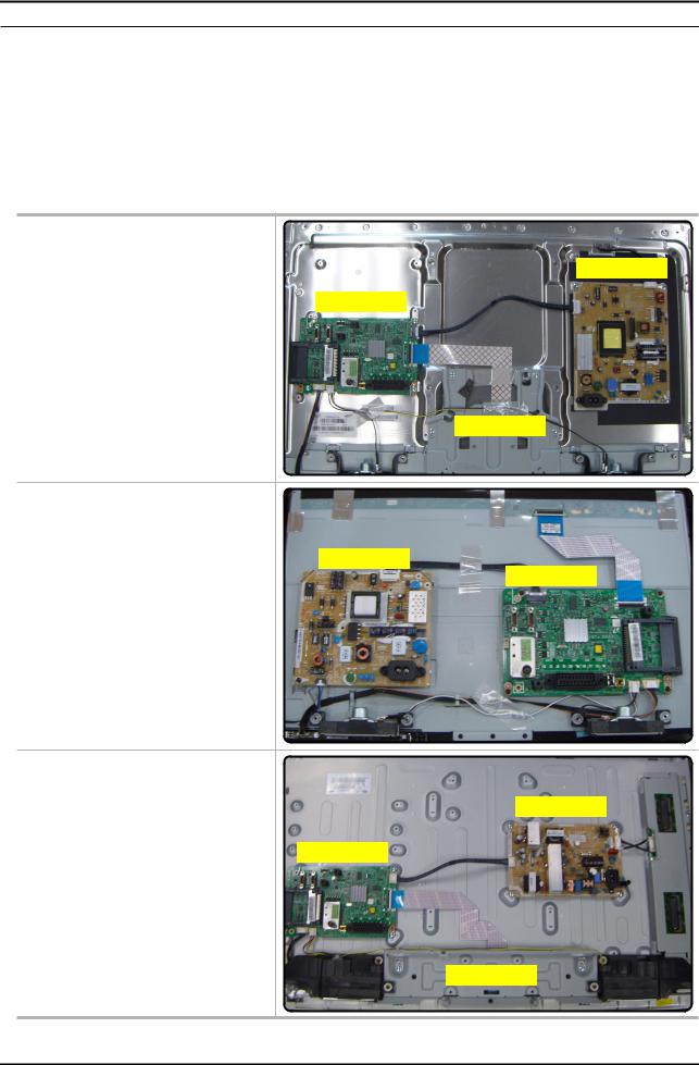
2.Check the power input to the Main Board.
UD4003(19", 26", 32") UD5003(22", 40")
SMPS BOARD
MAIN BOARD
T-CON
UD4003(19")
UD5003(22")
SMPS BOARD
MAIN BOARD
LD400 / LD403(32")
LD503(40")
SMPS BOARD
MAIN BOARD
T-CON
4-1
4. Troubleshooting
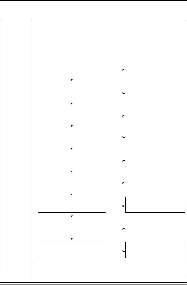
4-1-2. Flip (UE40D5003BW*** / UE26/32D4003BW*** / LE40D503F7W*** / LE32D400E1W*** / LE32D403E2W***)
No Power
Symptom |
-- The LEDs on the front panel do not work when connecting the power cord. |
||||||
-- The SMPS relay does not work when connecting the power cord. |
|
|
|||||
|
-- The units appears to be dead. |
|
|
|
|
||
|
The IP relay or the LEDs on the front panel does not work when connecting the power cord if the cables are |
||||||
Major |
improperly connected or the Main Board or SMPS is not functioning. In this case, check the following: |
||||||
-- Check the internal cable connection status inside the unit. |
|
|
|||||
checkpoints |
-- Check the fuses of each part. |
|
|
|
|
||
|
-- Check the output voltage of SMPS. |
|
|
|
|
||
|
-- Replace the Main Board. |
|
|
|
|
||
|
|
|
|
|
|
|
|
|
|
Lamp(Backlight) Off, |
No |
Change the 14p power cable. |
|
||
|
|
power indicator LED on? |
|
||||
|
|
|
|
|
|
||
|
|
|
|
|
|
|
|
|
|
|
Yes |
|
|
|
|
|
|
|
|
|
|
|
|
|
|
|
|
|
|
|
|
|
|
Lamp(Backlight) Off, |
No |
Change INVERTER/BALANCE B'D. |
|
||
|
|
power indicator LED on ? |
|
||||
|
|
|
|
|
|
||
|
|
|
|
|
|
|
|
|
|
|
Yes |
|
|
|
|
|
|
|
|
|
|
|
|
|
|
|
|
|
|
|
|
|
|
Does proper Stand-By DC A5V |
No |
|
|
||
|
|
appear at VIA - A5V_PW ? |
|
|
|||
|
|
|
|
|
|
||
|
|
|
|
|
|
|
|
|
|
|
Yes |
|
|
|
|
|
|
|
|
|
|
|
|
|
|
|
|
|
|
||
|
|
Does proper Main DC B13V, B5V |
No |
|
|
||
|
|
appear at VIA - B13V_PW, B5V_PW ? |
|
|
|
|
|
|
|
|
|
|
|
|
|
|
|
|
Yes |
|
|
Change the Main Assy. |
|
|
|
|
|
|
|
||
|
|
|
|
|
|
|
|
|
|
|
|
|
|
||
|
|
Does proper DC A3.3V |
No |
|
|
||
Diagnostics |
|
appear at VIA - A3.3V_PW ? |
|
|
|
|
|
|
|
|
|
|
|||
|
|
|
|
|
|
|
|
|
|
Yes |
|
|
|
|
|
|
|
|
|
|
|
|
|
|
|
|
|
|
|
|
|
|
|
|
|
|
|
||
|
|
Does proper B3.3V, B1.5V appear at |
No |
|
|
||
|
|
VIA - B3.3V_PW, B1.5V_PW |
|
|
|
|
|
|
|
|
|
|
|
|
|
|
|
|
Yes |
|
|
|
|
|
|
|
|
|
|
|
|
Does proper DC B13V
appear at LVDS connector No Change the LVDS cable.
Pin #1~5 of T-con b'd?
|
Yes |
|
|
|
|
|
|
|
|
||
|
|
|
|
||
Does proper DC B13V |
No |
Change the T-con b'd. |
|||
appear at F1 of T-con b'd? |
|||||
|
|
|
|||
|
|
|
|
|
|
Yes
Check a other function.
A power is supplied to set? No (No picture part)
Replace a LCD Panel.
Caution Make sure to disconnect the power before working on the IP board.
4-2
Loading...