


SAMSUNG Home Appliance Service
For the latest parts information, please access to our service web site (http://www.e4buyer.com/refrigerator)
SIDE-BY-SIDE REFRIGERATOR
Model:
RS20NCSL
RS20NCSW
RS20NESL
RS20NESW

WARNING
IMPORTANT SAFETY NOTICE
The service guide is for service men with adequate backgrounds of electrical, electronic, and mechanical experience. Any attempt to repair a major appliance may result in personal injury and property damage. The manufacturer or dealer cannot be responsible for the interpretation of this information.
SAMSUNG ELECTRONICS
Technical Service Guide
Copyright 2002
All rights reserved. This service guide may not be reproduced in whole or in part in any form without written permission from the SAMSUNG ELECTRONICS Company.
2

Contents
1.SAFETY WARNINGS 


 4
4
2.INSTRUCTION 


 6
6
3.INSTALLATION 


 7
7
4.NOMENCLATURE 


 8
8
5.SPECIFICATIONS 


 9
9
6.INTERIOR VIEWS AND DIMENSIONS 


 12
12
7.FREEZING CYCLE AND COOL AIR CIRCULATION ROUTE 


 14
14
8.MECHANICAL DISASSEMBLY


 16
16
9.FUNCTIONS AND OPERATION 


 22
22
10.CIRCUIT DESCRIPTION 


 27
27
11.DIAGNOSIS AND TROUBLESHOOTING 


 36
36
12.ILLUSTRATED PARTS CATALOGUE 


 42
42
 APPENDIX (CIRCUIT DIAGRAM)


 57
57
3
1.SAFETY WARNINGS
●Pull the power plug out already for the change or repair of electric parts.
→ Be careful the electric shock.
●When exchanging the parts, use the correct parts.
→Check the model name, rating voltage, rating current, running temperature symbols.
●When troubleshooting, connect firmly the types of harness. → Make not to be separated when some power is imposed.
●Check the traces of water infiltration at the electric parts.
→ If there is a trace of water infiltration, exchange or tape the parts.
●Check the assemble status of parts after troubleshooting. → It should be done indiscriminately as before the repair.
●Check the use circumstance of refrigerator.
→ If the refrigerator is installed at the place that is damp or wet, or status of installation is unstable, change the installation place.
● Do earth in case of need.
→ Particularly, Be sure to earth when there is a risk of an electric leakage by humidity or wetness.
● Do not use multi plugs in a plug socket at the same time.
Check the power cord and socket is damaged, pressed, squeezed, or fired.
→If the plug or plug socket is damaged, repair or exchange that immediately.
●Do not store the foods unstable or bottles in the freezing room.
●Do not repair the refrigerator by user himself.
●Do not store another materials except the foods.
→Drugs or scientific materials : difficult to keep a precise temperature.
→The inflammables(alcohol, benzene, ether, LP gas, butane gas etc.): have a risk of explosion.
4
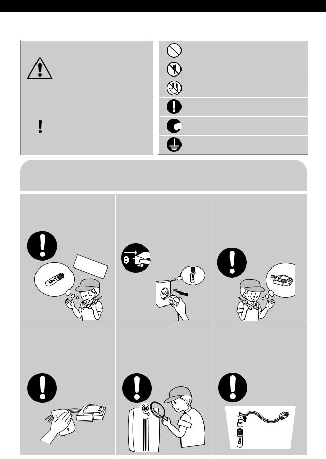
1. SAFETY WARNINGS
CAUTION / WARNING SYMBOLS DISPLAYED SYMBOLS
Indicates that a
 Warning danger of death or serious injury
exists.
Indicates that a risk
 Caution of personal injury or material damage
exists.
means “Prohibition”.
means “Do not disassemble”.
means “No contact”.
means ”The things to be followed”.
 means “Power cord should be
 unplugged from the consent”
means “Earth to prevent Electric shock”.
 Caution
Use the rated components |
Pull the power plug out to |
On repair, make sure that |
|
on the replacement. |
exchange the interior lamp |
the wires such as harness |
|
●Check the correct model, rated |
of the refrigerator. |
are bundled tightly. |
|
voltage, rated current, operating |
|||
|
●Bundle tightly wires in order not to |
||
temperature and so on. |
|
||
● It may cause electric shock. |
be detached by the external force and |
||
|
|||
|
|
then not to be wetted. |
On repair, remove |
After repair, check the |
Check if there is any trace |
||
completely dust or other |
assembled state of |
indicating the permeation |
||
things of housing parts, |
components. |
of water. |
||
harness parts, and check |
●It must be in the same assembled |
●If there is that kind of trace, change |
||
parts. |
state when compared with the state |
the related components or do the |
||
before disassembly. |
necessary treatment such as taping |
|||
●Cleaning may prevent the possible |
|
|||
|
using the insulating tape. |
|||
fire by tracking or short. |
|
|||
|
|
|
|
|
|
|
|
|
|
5
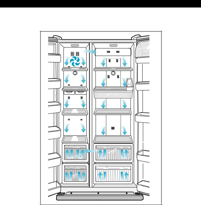
2. INSTRUCTION
 A newly developed SAMSUNG side by side refrigerator has the following characteristics.
1) Multi-Flow System
 Cool air circulates through multiple vents on each shelf level. This provides even distribution of cooling inside of freezer/refrigerator and keeps food fresher for longer.
2) High humidity for fresher food
 You can keep food, fruit and vegetables fresh for longer because your refrigerator supplies highly humidified cold air.
3) Door Alarm
 When the refrigerator door is left open for more than two minutes, a musical alarm is automatically triggered. This feature helps you save electricity and preserve stored foods.
6
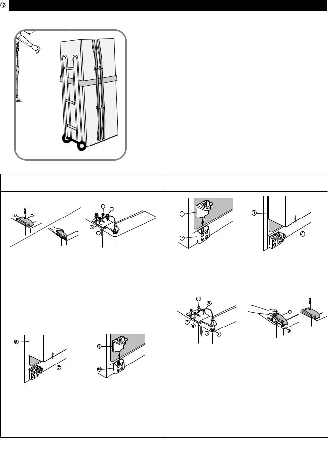
3. INSTALLATION
1)To protect refrigerator in movement
Use padded hand truck as shown. If entrance width is less than 30 , remove doors prior to installation and reattach doors according to procedure below.
2) Remove all protective tape and pad in refrigerators.
Please adjust the clearance between the doors.
3)Set the temperature control to the temperature and wait for an hour.
The refrigerator should get slightly chilled and the motor runs smoothly.
4)Once the refrigerator temperature is sufficiently cool
You can store food in the refrigerator. After starting the refrigerator, it takes a few hours to reach the appropriate temperature.
Disassemble the refrigerator |
|
Assemble the refrigerator |
|
1) |
2) |
1) |
2) |
1) With the door closed, disassemble screw( |
) by |
1) Insert the lower hinge ( ) in the bracket lower |
||||||
using (+) screw driver and then disassemble the |
||||||||
hinge ( ). |
|
|
|
|||||
upper hinge cover( |
). |
|
|
|
|
|||
|
|
|
|
|
||||
2) Disassemble bolts ( |
) and screws ( ) to the |
2) Assemble the door ( |
) in the lower hinge ( |
). |
||||
|
|
|
|
|||||
counter-clockwise by using a tool, and take off the |
3) |
4) |
|
|||||
upper hinge ( |
) along the arrow ( ). Take care |
|
|
|
|
|||
when you disassemble the door to ensure that it does |
|
|
|
|
||||
not fall on you. |
|
|
|
|
|
|
|
|
3) |
|
4) |
|
|
|
|
|
|
|
|
|
|
3) Insert the upper hinge shaft ( |
) into the hole ( |
). After |
||
|
|
|
|
leveling between the upper hinge hole ( ) and the |
||||
|
|
|
|
hole of the refrigerator ( |
), assemble bolts ( |
) |
||
3) Disassemble the door from the lower hinge ( ) by |
and screws ( ) to the clockwise by using a tool. |
|||||||
|
|
|
|
|||||
lifting the door ( ). |
|
|
4) Put the front part of the upper hinge cover ( |
) on the |
||||
|
|
|
|
|||||
4) Disassemble the lower hinge ( ) from the bracket |
front part of the upper hinge ( |
) and assemble, |
||||||
lower hinge ( |
) by lifting the lower hinge ( |
) in the |
starting with the front part of the upper hinge |
|||||
direction of the arrow. |
|
|
cover. Assemble the screw to the clock wise by |
|||||
|
|
|
|
using a tool. |
|
|
|
|
7
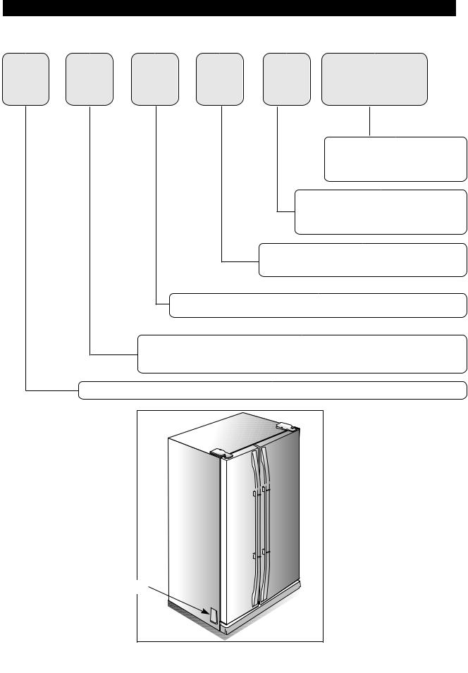
4. NOMENCLATURE
R S 20 N C |
SW |
Color
SW : Snow White
SL : Stainless Looking
Handle
C ; Sky
E ;
Option
N : Nothing
Capacity ; Cu. ft
Door Type
S - Side By Side
Product ; R - |
Label Location |
8 |
5. SPECIFICATIONS
5-1. Model Specification
|
|
Items |
|
|
|
Specification |
|
|||||
|
|
|
|
|
|
|
|
|
|
|
|
|
|
|
Model Name |
|
|
RS20N*** |
|
|
|
||||
Volume |
|
Total Volume |
|
496 l(17.5 cu.ft) |
|
|||||||
|
|
|
|
|
|
|
|
|
|
|
|
|
|
Freezer Volume |
|
188 l(6.6 cu.ft) |
|
||||||||
capacity |
|
|
|
|||||||||
|
|
|
|
|
|
|
|
|
|
|
|
|
|
|
Refrigerator Volume |
|
308 l(10.9 cu.ft) |
|
|||||||
|
|
|
|
|
|
|
|
|
||||
Outer dimensions(width x depth x height) |
850mm×724mm×1722mm |
|
||||||||||
|
Rated frequency |
Hz |
60 |
60 |
|
50 |
|
|
50/60 |
|
50 |
|
|
|
|
|
|
|
|
|
|
|
|
|
|
|
Rated voltage |
V |
110 115 |
127 |
|
220 |
|
|
220 |
|
230 |
|
|
|
|
|
|
|
|
|
|
|
|
||
Rated consumption of Comp W |
140 |
125 |
|
120 |
|
|
140 |
|
125 |
|||
|
|
|
|
|
|
|
|
|
|
|
||
Rated consumption of Electric heater W |
|
|
394 |
|
|
|
|
|
||||
|
|
|
|
|
|
|
|
|
|
|
||
|
Refrigerator type |
|
|
Frost free |
|
|
|
|||||
|
|
|
|
|
|
|
|
|
|
|
|
|
|
|
Refrigerant |
|
|
|
HFC - 134a |
|
|
|
|||
|
|
|
|
|
|
|
|
|
|
|
||
|
Refrigerant quantity |
|
|
|
190gr |
|
|
|
||||
|
|
|
|
|
|
|
|
|
|
|
|
|
|
Freezing Capacity |
|
|
|
|
|
|
|
|
|
||
|
|
|
|
|
|
|
|
|
|
|||
|
|
|
|
|
|
|
|
|
|
|
|
|
|
Products weight |
|
|
|
106kg |
|
|
|
||||
|
|
|
|
|
|
|
|
|
|
|
|
|
9
5-2. Electric Parts Specification
Freezing parts
Inner Temperature detection parts
Parts related defrost
|
Items |
|
|
|
|
|
Specification |
|||||||||
|
Model Name |
|
|
|
RS20N*** |
|
|
|
||||||||
|
Performance of freezer |
|
|
|
|
|
|
|
|
|
|
|
|
|||
|
|
|
|
|
|
|
|
|
|
|
|
|
||||
|
|
|
|
Type |
110V/60Hz |
|
127V/60Hz |
|
220V/50Hz |
|
220V/50,60Hz |
|
230V/50Hz |
|||
|
|
|
|
|
|
|
|
|||||||||
|
|
|
|
|
|
|
|
|
|
|
|
|
|
|
|
|
|
|
MK183CL2U/EH1 |
|
MK183PL2U/EO1 |
|
DK190KT2U/EO1 |
|
SK190HL2U/E01 |
|
MK183QL2U/EO1 |
||||||
|
|
|
|
|
|
|
|
|
||||||||
Compressor |
|
|
|
|
|
|
|
|
|
|
|
|
|
|
|
|
|
|
Operation type |
|
|
|
|
|
R.S.C.R |
|
|
|
|||||
|
|
|
|
|
|
|
|
|
|
|
|
|
|
|
|
|
|
|
|
|
Sealing oils |
|
|
FREOL α- 15 (ESTER) |
|||||||||
|
|
|
|
|
|
|
|
|
|
|
|
|
|
|
|
|
|
Cooler |
|
|
Freezer |
|
|
SPLIT FIN TYPE |
|||||||||
|
|
|
|
|
|
|
|
|
|
|
|
|
|
|
||
|
Condensing method |
Force and natural convection method |
||||||||||||||
|
|
|
|
|
|
|
|
|
|
|
|
|
|
|
||
|
Drying agent |
|
|
MOLECULAR SIEVE XH-9 |
||||||||||||
|
|
|
|
|
|
|
|
|
|
|
|
|
|
|
||
|
Capillary tube |
|
|
0.82×3200, 5.5 kg/cm2 |
||||||||||||
|
Refrigerant |
|
|
|
HFC-134a |
|
|
|
||||||||
|
Types |
|
|
Freezer temp. |
ON( ) |
|
|
|
OFF( ) |
|||||||
|
|
|
|
|
|
|||||||||||
Freezer |
|
|
|
|
|
|
|
|
|
|
|
|
|
|
|
|
(F-sensor) |
|
|
Normal |
-19.0 |
|
|
|
|
|
|
-21.0 |
|||||
|
Thermistor |
|
|
Colder |
-24.0 |
|
|
|
|
|
|
-26.0 |
||||
|
502AT |
|
|
|
|
|
|
|
|
|
|
|
|
|
|
|
|
|
|
Cold |
-15.0 |
|
|
|
|
|
|
-17.0 |
|||||
|
|
|
|
|
|
|
|
|
|
|||||||
|
|
|
|
|
|
|
|
|
|
|
|
|
|
|
|
|
Refrigerator |
Types |
|
|
Refrigerator temp. |
ON( ) |
|
|
|
OFF( ) |
|||||||
|
|
|
|
|
|
|
|
|
|
|
|
|
|
|
|
|
Thermistor |
|
|
Colder |
2.0 |
|
|
|
|
|
|
0.0 |
|
|
|||
|
|
|
|
|
|
|
|
|
|
|
||||||
|
|
|
|
|
|
|
|
|
|
|
|
|
|
|
|
|
|
(R-sensor) |
|
|
Normal |
4.0 |
|
|
|
|
|
|
2.0 |
|
|
||
|
502AT |
|
|
|
|
|
|
|
|
|
|
|
|
|
|
|
|
|
|
Cold |
7.0 |
|
|
|
|
|
|
5.0 |
|
|
|||
|
|
|
|
|
|
|
|
|
|
|
|
|||||
|
|
|
|
|
|
|
|
|
|
|
|
|
|
|||
Defrostperiod |
Period of initial defrost (F defrost) |
|
|
4 hours ± 10 mins |
||||||||||||
|
|
|
|
|
|
|
|
|
|
|
|
|
|
|
||
|
Pause |
|
|
7 ± 2 minutes |
||||||||||||
|
Defrost period of freezer |
6~11 hours(Variable according to the use conditions)defrost |
||||||||||||||
|
|
|
|
|
|
|
|
|
|
|
|
|
|
|
|
|
Defrost sensor |
sensor |
|
|
Spec |
|
|
5.0 at 25 |
|
|
|
||||||
|
F-defrost |
|
|
Types |
|
|
THERMISTOR (PX41C) |
|||||||||
|
|
|
|
|
|
|
|
|
|
|
|
|
|
|
|
|
Temperature fuse |
|
|
Rating |
|
|
AC 250V 10A |
||||||||||
|
|
|
|
|
|
|
|
|
|
|
|
|
|
|
||
|
|
Operation temp. |
+0 |
|
|
|
|
|
|
|||||||
|
|
|
|
|
|
|
|
|
|
|||||||
|
|
|
|
|
|
|
77 - 5 |
|
|
|
||||||
10
|
|
|
|
|
|
|
|
|
|
|
|
|
|
|
|
|
|
|
|
|
|
|
|
|
|
|
|
|
|
|
|
|
|
|
|
Items |
|
|
|
|
Specification |
|
|
|
|
|||||
|
|
|
|
|
|
|
|
|
|
|
|
|
|
|
|
|
|
|
F-room defrost heater |
Conducting at F defrosting |
|
|
|
|
200W |
|
|
|
|
|
|
||
|
|
F room heater sub |
Conducting at F defrosting |
|
|
|
|
|
60W |
|
|
|
|
|
|
|
|
|
|
|
|
|
|
|
|
|
|
|
|
|
|
|
|
|
|
F room heater glass |
Conducting at F defrosting |
|
|
|
|
130W |
|
|
|
|
|
|
||
|
|
|
|
|
|
|
|
|
|
|
|
|
|
|
|
|
|
|
R-room cover damper |
|
|
|
|
|
3W |
|
|
|
|
|
|
||
|
|
|
|
|
|
|
|
|
|
|
|
|
|
|
|
|
|
|
R room electrically driven damper |
|
|
|
|
|
1W |
|
|
|
|
|
|
||
|
|
|
|
|
|
|
|
|
|
|
|
|
|
|
||
|
|
Condenser for |
Running |
250VAC,12 |
250VAC,12 |
350VAC,5 |
350VAC,5 |
350VAC,5 |
||||||||
|
|
Comp.(monolithic) |
Start |
- |
|
|
- |
|
- |
|
- |
|
- |
|
|
|
|
|
Start relay |
Type |
J531Q32E4R7M1802 |
J531Q32E4R7M1802 |
J531Q34E220M3502 |
J531Q34E220M3502 |
J531Q35E330M3852 |
|
|||||||
|
|
Action |
Initial resistance: 68Ω±20% (Ambient temperature : 25 ) |
|
||||||||||||
|
|
|
||||||||||||||
|
Electricparts |
|
OFF temperature |
4TM437RHBYY-53 |
4TM437RHBYY-53 |
69 ± 9 |
4TM317SHBYY-53 |
4TM265RHBYY-53 |
|
|||||||
|
|
|
Type |
4TM317SHBYY-53 |
||||||||||||
|
|
Overload relay |
ON temperature |
|
|
|
130 ± 5 |
|
|
|
|
|||||
|
|
|
|
|
|
|
|
|
|
|
|
|
|
|
||
|
|
L.V.T(LOW VOLTAGE TRANSFORMER) |
110 115V/60Hz |
|
127V/60Hz |
|
220V/50Hz |
230 240V/50Hz |
||||||||
|
|
|
|
|
|
|
|
|
|
|
|
|
|
|
|
|
|
|
F room cooling fan motor |
|
DC 12V DREP3030LA 0.3A |
|
|
|
|
||||||||
|
|
|
|
|
|
|
|
|
||||||||
|
|
Comp. Cooling fan motor |
|
DC 12V DRCP3030LA 0.24A |
|
|||||||||||
|
|
|
|
|
||||||||||||
|
|
Freezer interior light |
30W (110 |
127V) |
|
25W (220 |
230V) |
|
||||||||
|
|
|
|
|
|
|
|
|
|
|
|
|
|
|
|
|
|
|
Refrigerator interior light |
30W (110 |
127V) |
|
25W (220 |
230V) |
|||||||||
|
|
|
|
|
||||||||||||
|
|
Door switch |
|
|
|
AC 250V 0.5A |
2EA |
|
|
|
|
|||||
|
|
|
|
|
|
|
|
|
|
|
||||||
|
|
Supply cord |
TO BE FOLLOWED LOCAL STANDARD |
|
||||||||||||
|
|
|
|
|||||||||||||
|
|
Grounding screw |
|
BSBN (Bronze screw)×4EA |
|
|
|
|
||||||||
|
|
|
|
|
|
|
|
|
||||||||
11
6. INTERIOR VIEWS AND DIMENSIONS
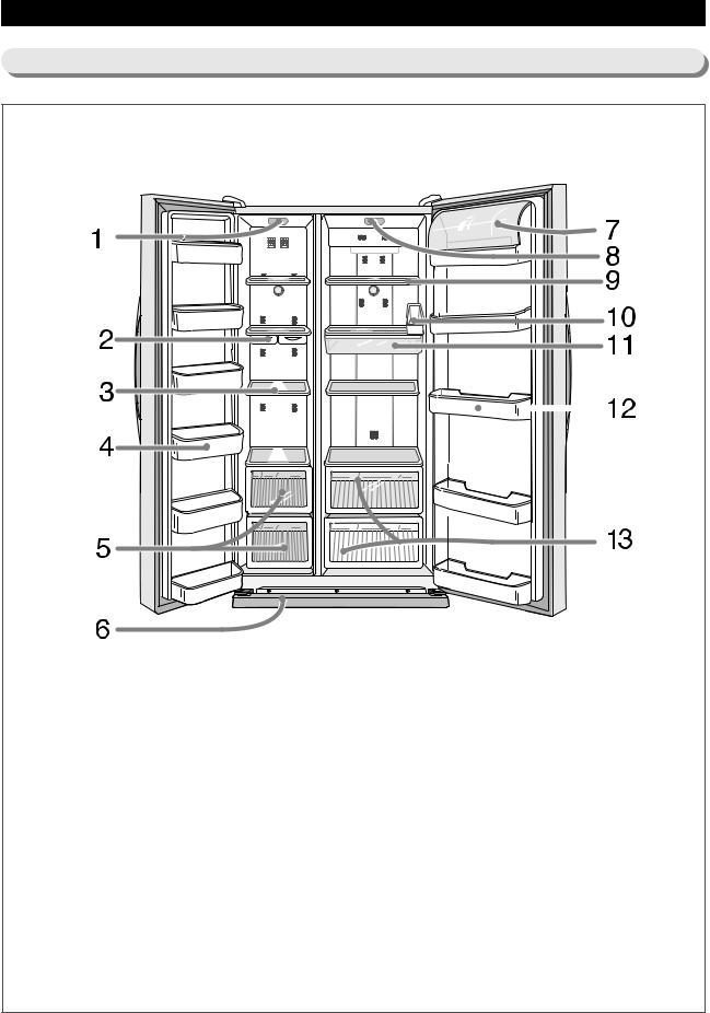
6-1. The Name of Each Part
Freezer |
|
Refrigerator |
|
Interior light |
|
Dairy compartment |
|
Ice tray |
|
Interior light |
|
Shelf |
|
Shelf |
|
Food Guard |
|
Egg tray |
|
Drawer |
|
Fresh container(option) |
|
Leg cover |
|
Food Guard |
|
|
|
Vegetable and fruit drawer |
|
12
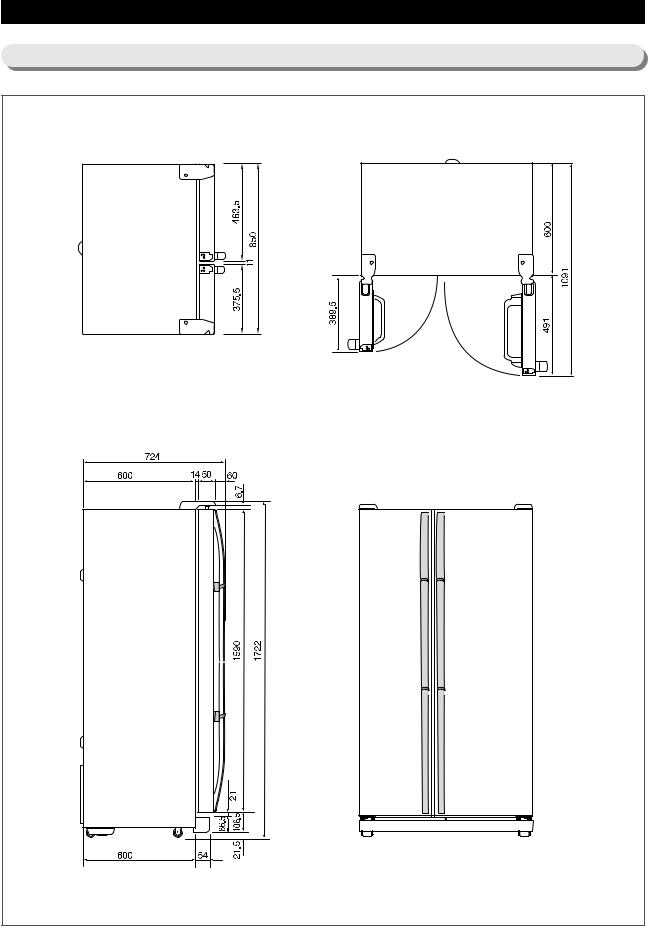
6-2. Dimensions of Unit
13
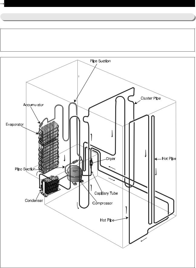
7. FREEZING CYCLE AND COOL AIR CIRCULATION ROUTE
7-1. Freezing Cycle
Compressor Condenser |
Pipe cluster |
Pipe hot |
Dryer |
Capillary tube |
Evaporator |
Accumulator |
Pipe suction |
Compressor |
|
|
|
14 |

7-2. Cooling Air Circulation
Freezer |
Refrigerator |
|
15 |
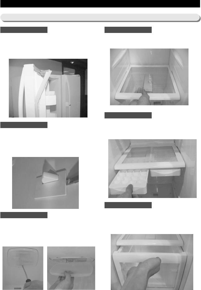
8. MECHANICAL DISASSEMBLY
8-1. Accessories for storage and parts for lightening
Door Gasket
The door gasket is set into groove on door liner.
1)Open the door.
2)Grasp the gasket and pull it out from the door liner.
LIGHT SWITCHES
The unit have two light switches on the side wall of freezer & refrigerator.
1)Use a small flat-blade screw driver to unlock the hook and pull the switch out until the wire connector is exposed.
LIGHTS
The light of freezer & refrigerator are located at upper side of each compartment.
1)Remove the screws.
2)Remove the lamp cover by unlocking the hook.
SHELVES
1)Pull the shelf out as far as it goes.
2)Lift it up and pull it out from the unit.
ICE TRAYS
The ice tray is located at bottom of freezer shelfmid.
1) Pull the tray out by sliding.
DRAWERS
The drawers are located at bottom side of freezer and refrigerator.
1)Pull the drawer out as far as it goes.
2)Lift it up slightly and pull it out from the unit.
16
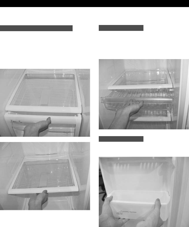
SHELF LOW REF. IN REFIGERATOR
The shelf low ref. in refrigerator can be removed as following sequence.
1)First, remove the drawer upp..
2)Pull the shelf out as far as it goes.
3)Lift it up and pull it out from the unit.
TRAY-REF
The tray-ref is located at bottom of shelf-ref in refrigerator compartment.
1)Pull the tray-ref out as far as it goes.
2)Lift it up slightly and pull it out from the shelf.
FOOD GUARDS
1) Lift the guard up and pull it out from door liner.
17

8-2. Cooling Unit
COVER EVAP FRONT IN FREEZER
Before disassemble the cover, Should be removed all accessories in freezer.
1)Pull the screw cap out (4 EA).
2)Remove the screws (6 EA).
3)Grasp the bottom edge of the cover, and pull it out from the unit.
COVER DUCT FRONT IN FREEZER
Before disassemble the cover, should be cover evap. front.
1)Pull the screw cap out (1 EA).
2)Remove the screws (1 EA).
3)Grasp the bottom edge of the cover, and pull it out from the unit.
4)Disconnect the sensor wire connector and pull the cover out from the unt.
COVER DUCT REAR IN FREEZER
Before disassemble the cover, Should be removed cover duct. front.
1)Remove the screws (3 EA).
2)Grasp the bottom edge of the cover, and pull it out from the unit.
3)Disconnect the wire connector and pull the cover out from the unt.
FAN MOTOR
1)Remove the fan propeller (1 EA).
2)Disconnect the wire connector from body of the cover.
3)Remove the screws (3 EA) and separate the fan motor case.
4)Open the case and remove fan motor.
18
 Loading...