


Samsung 2 Door 2 Drawer Convertible Side by Side Training Manual
RM255BARB
RM255BASB
RM255BABB
|
|
|
|
|
|
|
|
|
|
|
|
|
|
|
|
|
|
|
|
|
|
|
|
|
|
|
|
|
|
|
|
|
|
|
|
|
|
|
|
|
|
|
|
|
|
|
|
|
|
|
|
|
|
|
Maytag Technical Institute, 2006 |
|
|
|
|
|
|
|
|
|
L2006-028 |
|
|
|
|
|
|
|
|
|
||
|
|
|
|
|
|
|
|
|

Authorized Training Center Campuses
Maytag maintains an affiliation with ten institutions in the US and Canada to offer technical training sessions focused on Maytag branded product. Maytag supplies the course content and product but each school operates as an independent agent and collects fees accordingly. All training sessions include classroom (30%) and lab time (70%) and cover both basic and advanced troubleshooting techniques. There are three standard one-week courses, Laundry, Refrigeration and Kitchen (Cooking and Dishwashers) and shorter 1, 2 and 3-day offerings. Check the MAC website or LTS publications for class schedules. Contact the schools for additional information and brochures
Kwantlen University |
Hibbing Community College |
College |
|
12666 72nd Ave |
1515 East 25th St |
Surrey, BC |
Hibbing, MN. 55746 |
Canada V3W2M8 |
218-262-7231 |
604-599-2962 |
|
Los Mendanos College
2700 East Leland Rd
Pittsburg, CA 94565
925-439-2181
Center for Manufacturing Excellence 3000 Log City Trail Galesburg, IL 61401
309-345-3501
Bay State School of Technology
225 Turnpike St
Canton, MA. 02021
888-828-3434
Elizabethtown Technical College
610 College St Rd
Elizabethtown KY 42701
270-769-2371
Appliance Repair Institute |
Tulsa Technology Center |
|
|
275 South G St |
3850 North Peoria |
Miami Lakes |
|
San Bernadino, CA 92410 |
Tulsa, OK 74147-7200 |
||
Education Center |
|||
909-888-3600 |
918-828-2038 |
||
5780 NW 158th St |
|||
|
|
||
|
Louisiana Technical College |
Miami, FL 33014 |
|
|
305-557-1100 EXT 2332 |
||
|
111 Pride Dr |
|
|
|
Hammond, LA 70404-0489 |
|
|
|
985-543-4123 |
|

WARNING
IMPORTANT SAFETY NOTICE
This service guide is for service technicians with adequate backgrounds and electrical, electronic, and mechanical experience. Any attempt to repair a major appliance may result in personal injury and property damage.The manufacturer or dealer cannot be responsible for the interpretation of this information.
SAMSUNG ELECTRONICS AMERICA, INC.
Technical Service Guide
Copyright 2005
All rights reserved. This service guide may not be reproduced in whole or in part in any form without written permission from the SAMSUNG ELECTRONICS Company.
CONTENTS
PRECAUTIONS................................................................................... |
5 |
PRODUCT SPECIFICATIONS ........................................................... |
8 |
OPERATING INSTRUCTIONS & INSTALLATION........................ |
13 |
DIASSEMBLY and REASSEMBLY................................................... |
24 |
TROUBLESHOOTING........................................................................ |
37 |
WIRING DIAGRAM............................................................................ |
60 |
PCB DIAGRAM................................................................................... |
73 |
CIRCUIT (SCHEMATIC) DIAGRAM................................................ |
74 |
CURCUIT DESCRIPTIONS................................................................ |
75 |
REFERENCE INFORMATION........................................................... |
81 |

1. PRECAUTIONS(SAFETY WARNINGS)
Unplug the refrigerator before making any repairs or any replacements. Avoid electric shock.
Use rated components for the replacements.
Check that they have the correct model number, rated voltage, rated current, operating temperature and so on.
On repair, be sure that the wires such as harness are bundled tightly and are not exposed by water.
Bundle wires tightly in order not to be detached by an the external force.
Upon repair, completely remove dust, particles or other items from housing areas, harness parts, and connectors.
Cleaning may prevent fire by tracking or short.
Check if there is any trace of water infitration on electrical parts.
If there is kind of trace, change the related components or do the necessary action such as taping using the insulating tape.
After repair, check the appearance of the assembled parts.
They must look the same as they did before disassembly.
Check the conditions surrounding the installed refrigerator.
When the refrigerator is located at humid or wet place, or the installed state is unstable, change the location.
If necessary instal a ground conductor.
This appliance must be properly grounded, especially if there is a possibility of electrical leakage.
Do not allow consumers to use one outlet for several plugs.
Check whether the power cord has been placed under an other appliance and gotten, damaged, worn-out squeezed.
Repair the defective power plug or outlet immediately.
Make sure that the power cord is not placed under an other appliance or pinched.
Do not allow consumers to keep bottles or the likes in the Freezer or to keep foods in unstable positions.
Do not allow consumers to repair the appliance by themselves.
Do not allow consumers to keep other chemicals except food.
Medicines and other materials for research, this appliance will not maintain the precisely constant temperature for them.
Volatile materials (Alcohol, Benzene, Ether, LP gas etc.) - possibility of explosion
4
PRECAUTIONS(SAFETY WARNINGS)
Read all instructions before repairing the product, and follow to the instructions in order to prevent danger or property damage.
CAUTION/WARNING SYMBOLS DISPLAYED
Indicates that a
danger of death Warning or serious injury
exists.
Indicates that a risk
of personal injury Caution or material damage
exists.
SYMBOLS
 means “Forbidden”.
 means “do not disassemble”.
 means “do not touch”
means “Instructions that need to be followed”
 means “power cord should be

 unplugged from the consent”
means “Ground to prevent Electric shock”.
 Warning & Caution
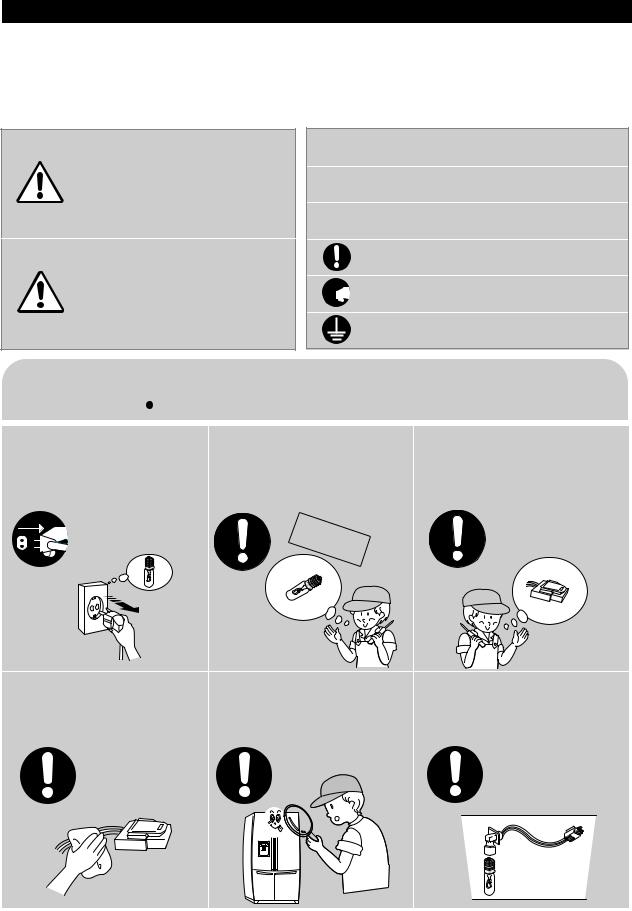
Pull the power plug out to exchange the interior lamp of the refrigerator.
It may cause electric shock.
Unplug
Use rated components for the replacement.
Check for the correct model, rated voltage, rated current, operating temperature and so on.
componentsRated
Upon repair, make sure that the wires such as harness are bundled tightly.
Bundle wires tightly for them not to be detached by an external force and not to get wet.
Uponrepair,removecompletelydustor otheritemsformthehousingareas, harnesses,andcheckpartsappearance.
Cleaning may prevent the possible fire by tracking or short.
After repair, check the appearance of the assembled components.
IThey must look the same as they did before disassembly.
Check if there is any trace indicating water permeation.
If there is that kind of trace, change the related components or do the
necessary treatment such as taping using the insulating tape.
5

PRECAUTIONS(SAFETY WARNINGS)
Please ler users know following warnings & cautions in detail.
 Warning & Caution
Do not allow users to put glass |
Do not allow users to store narrow |
Do not allow users to store |
bottles or similar in the freezer. |
and long bottles or foods in a small |
pharmaceutical products, scientific |
|
multi-purpose room. |
materials, etc., in the refrigerator. |
Freezing the contents may cause . |
It may hurt you when the refrigerator door |
Products which require temperature control |
|
is opened and closed resulting in stuff falling |
should not be stored in the refrigerator. |
|
down. |
|
Forbidden |
Forbidden |
Forbidden |
Do not allow users to insert the |
Do not allow users to |
Do not allow users to bend the |
|
power plugs for many products |
disassemble, repair or alter. |
power cord with excessive force or |
|
at the same time. |
It may cause fire or abnormal operation |
do not allow the power |
|
cord to get pinched by a heavy item. |
|||
May cause abnormal generation of |
leading to injury. |
||
May cause fire. |
|||
heat or fire. |
|
||
|
|
Forbidden |
Do not |
disassemble 
Do not allow users to store |
Do not allow users to install the |
Ensure grounding. |
|
articles on top of the product. |
refrigerator in a wet place or a |
If grounding is not done, it will cause |
|
place where water splashes. |
|||
Opening or closing the door may cause |
breakdown and electric shock. |
||
Deterioration of the insulation of electric |
|
||
things to fall down, witch may cause injury. |
|
||
parts may cause electric shock or fire. |
|
||
|
|
Forbidden
Ground
6
2. PRODUCT SPECIFICATIONS
2-1) |
Introduction of main functions................................................... |
8 |
2-2) |
Model Specifications.................................................................. |
9 |
2-4) |
Electric Parts Specifications....................................................... |
10 |
2-6) |
Optional Material Specifications................................................ |
12 |

PRODUCT SPECIFICATIONS
2-1) Introduction of main function
THE SAMSUNG side by side refrigerator has the following characteristics:
TDM System(Time-Divided-Multi-evaporator system)
• Each compartment has one evaporator, so this refrigerator has 4 evaporators. Also, microprocessors and a refrigerant control valve control the refrigeration cycle of the 4 evaporators to achieve high efficiency and high humidity in the fridge. Food odor from one compartment of the refrigerator does not affect food in the other compartments because of separate cooler and air flow systems.
Multi-Flow System
• Cool air circulates through multiple vents on every shelf level. This provides even distribution of cooling inside cabinets to keep your food fresh longer.
|
Door Alarm |
|
• A beeper reminds you that the door is open. |
|
Xtra FreshTM |
|
• Optimized humidity control keeps vegetables & fruits fresh. |
|
Arctic Select ZoneTM Drawer |
|
• The Arctic Select Zone Drawer is convertible from a freezer |
|
to a refrigerator by the TDM system. The user can select |
|
Power Freeze, Freezer, Soft Freeze, or Cool according to the |
|
type of food. |
|
Fresh Select ZoneTM Drawer |
|
• The user can select Soft Freeze, Chill, Cool or Fresh |
|
according to the type of food. Especially in Cool and Fresh, |
|
the drawer humidity is high by the TDM system. |
|
This operation instruction covers various models. |
NOTE |
The characteristics of your appliance may differ slightly from those described in this |
|
manual. |
9
8

PRODUCT SPECIFICATIONS
2-2) Model Specification
Item |
Specification |
|
|
|
|
RM25 |
|
|
|||||
|
|
|
|
|
|
|
|||
|
Dispenser without beverage station |
||||||||
|
|
|
|||||||
|
|
|
|
|
|
|
|
|
|
|
|
Total |
|
|
24.8 ft3 |
|
|||
|
|
Fridge |
|
|
11.6 ft3 |
|
|||
Net Capacity |
|
Freezer |
|
|
7.0 ft3 |
|
|||
|
|
CR |
|
|
3.8 ft |
3 |
|
||
|
|
Fresh Select Zone |
|
|
|
|
|||
|
|
CF |
|
|
2.4 ft3 |
|
|||
|
|
Arctic Select Zone |
|
|
|
|
|
|
|
|
7 |
1 |
|
|
|||||
38 |
|
35 |
|
|
70 |
||||
8 |
4 |
|
|||||||
Rated Voltage and Frequency |
115V/60Hz |
||||||||
|
|
|
|
|
|
|
|
||
Motor Rated Power Consumption |
|
|
183W |
|
|||||
|
|
|
|
|
|
|
|
||
Electric Heater Rated Power Consumption |
|
|
470W |
|
|||||
|
|
|
|
|
|
|
|||
Refrigerator Type |
Indirect Cooling Method Refrigerator |
||||||||
|
|
|
|
|
|
|
|
||
Refrigerant |
|
|
R-134a |
|
|||||
|
|
|
|
|
|
|
|||
Refrigerant Input Amount |
235g(8.29oz) |
||||||||
|
|
|
|
|
|
|
|
||
Product Weight |
before packing : 353lbs |
||||||||
after packing : 386lbs |
|||||||||
|
|
|
|||||||
9
PRODUCT SPECIFICATIONS
2-4) Electric Parts Specification
|
|
|
Item |
|
Specification |
|
|
|
|||
|
|
|
Model |
|
RM25 |
|
|
|
|||
|
|
|
|
Model |
|
|
MK183C-L2U |
|
|
|
|
|
Compressor |
Starting type |
|
|
R.S.C.R |
|
|
|
|||
|
|
|
|
Oil Charge |
|
FREOL |
- 10 (ESTER) |
|
|
||
Components |
|
|
|
Freezer |
|
SPLIT FIN TYPE |
|
|
|
||
Evaporator |
Fridge |
|
SPLIT FIN TYPE |
|
|
|
|||||
|
|
|
|
|
|||||||
|
CR |
|
SPLIT FIN TYPE |
|
|
|
|||||
|
|
|
|
|
|
|
|
||||
|
|
|
|
Fresh Select Zone |
|
|
|
|
|
|
|
|
|
|
|
CF |
|
SPLIT FIN TYPE |
|
|
|
||
|
|
|
|
Arctic Select Zone |
|
|
|
|
|
|
|
Freezer |
|
|
Condenser |
Forced and natural convection type |
|
|
|||||
|
|
|
Dryer |
|
Molecular sieve XH-9 |
|
|
|
|||
|
|
|
|
|
|
|
|
||||
|
|
|
|
|
F capi 0.85 |
3300mm(0.033 |
129.9 |
) |
|||
|
|
|
Capillary tube |
R capi 0.85 |
3000mm(0.033 |
118.1 |
) |
||||
|
|
|
|
|
C capi 3.56 |
650mm(0.140 |
25.6 ) |
|
|||
|
|
|
|
|
|
|
|
|
|
|
|
|
|
|
Refrigerant |
|
|
R-134a |
|
|
|
||
Components |
Freezer |
|
Model |
Temperature Selection |
ON( |
) |
|
OFF( |
) |
|
|
|
THERMISTOR |
-14 |
-12 |
|
|
|
-16 |
|
|
||
|
|
|
(F-SENSOR) |
-2 |
0 |
|
|
|
-4 |
|
|
|
|
|
502AT |
6 |
8 |
|
|
|
4 |
|
|
TemperatureSensor |
RefrigeratorCycle |
|
Model |
Temperature Selection |
ON( |
) |
|
OFF( |
) |
|
|
|
Defrost Cycle(FRE) |
8 ~ 16hr (varies according to conditions of use) |
|||||||||
|
|
|
THERMISTOR |
34 |
36 |
|
|
|
32 |
|
|
|
|
|
(R-SENSOR) |
38 |
40 |
|
|
|
36 |
|
|
|
|
|
502AT |
46 |
48 |
|
|
|
44 |
|
|
|
|
|
|
|
|
|
|
|
|||
|
|
|
First Defrost Cycle (Concurrent defrost of F and R) |
|
|
4 hr |
10 min |
|
|
|
|
Room |
Defrost |
|
|
|
|
|
|
|
|
|
|
|
|
Pause time |
|
|
10 |
1 min |
|
|
|
||
|
|
|
Defrost Cycle(REF) |
8 ~ 16 hr (varies according to conditions of use) |
|||||||
|
|
|
|
|
|
|
|
|
|
||
ComponentsRelated |
|
|
R Defrost- |
Model |
|
THERMISTOR (502AT) |
|
|
|||
CycleDefrost |
|
Sensor |
SPEC |
|
|
5.0 |
at 77 |
|
|
|
|
|
|
|
|
|
|
|
|
||||
|
|
|
|
|
|
|
|
|
|
||
|
|
|
F Defrost- |
Model |
|
THERMISTOR (502AT) |
|
|
|||
|
|
|
Sensor |
SPEC |
|
|
5.0 |
at 77 |
|
|
|
|
|
|
|
|
|
|
|
|
|
||
|
|
|
CF Defrost- |
Model |
|
THERMISTOR (502AT) |
|
|
|||
|
|
|
Sensor |
SPEC |
|
|
5.0 |
at 77 |
|
|
|
|
|
|
|
|
|
|
|
|
|
||
Defrost |
|
|
CR Defrost- |
Model |
|
THERMISTOR (502AT) |
|
|
|||
|
|
Sensor |
SPEC |
|
|
5.0 |
at 77 |
|
|
|
|
|
|
|
|
|
|
|
|
||||
|
|
|
|
|
|
|
|
|
|||
|
|
Bimetal |
Operating temperature |
60 OFF / 40 |
ON(140 OFF / 104 |
ON) |
|||||
|
|
|
|
|
|
|
|
|
|
|
|
10

PRODUCT SPECIFICATIONS
Electric Components
|
Items |
|
Specifications |
|
||||||
|
Model |
Dispenser |
|
|
|
Home Bar |
|
|||
|
|
|
|
|
||||||
|
Defrost-Heater(FRE) |
|
Conducting F Defrosting |
|
|
|
|
|
||
|
|
|
200W |
|
|
|||||
|
|
|
|
|
|
|
|
|
|
|
|
Defrost-Heater(REF) |
|
Conducting R Defrosting |
|
80 W |
|
|
|||
|
|
|
|
|
|
|
|
|
|
|
|
Defrost-Heater(CF) |
|
Conducting CF Defrosting |
|
100 W |
|
|
|||
|
|
|
|
|
|
|
|
|
|
|
|
Defrost-Heater(CR) |
|
Conducting CR Defrosting |
|
80 W |
|
|
|||
|
|
|
|
|
|
|
|
|
|
|
|
DRAIN PIPE(FRE) |
|
Conducting F Defrosting |
|
5 W |
|
|
|||
|
|
|
|
|
|
|
|
|
|
|
|
DRAIN PIPE(REF) |
|
Conducting R Defrosting |
|
5 W |
|
|
|||
|
|
|
|
|
|
|
|
|
|
|
|
DISPENSER Heater |
|
Interlock with F-FAN |
|
|
7W |
|
|
||
|
WATER PIPE Heater |
|
- |
|
|
5W |
|
|
||
|
WATER TANK Heater |
|
- |
|
|
3W |
|
|
||
|
Bimetal |
60 |
OFF / 40 |
ON |
|
|||||
|
(140 |
OFF / 104 |
ON) |
|
||||||
|
|
|
|
|
|
|||||
|
|
|
|
|
|
|
|
|
|
|
|
Condenser for |
|
|
Running |
|
250VAC-12 F |
|
|
||
|
COMP |
|
|
|
|
|
|
|
|
|
|
|
|
Starting |
|
|
- |
|
|
||
|
(Package type) |
|
|
|
|
|
|
|||
|
|
|
|
|
|
|
|
|||
|
Starting-Relay |
|
|
Model |
J531Q32E4R7M182 |
|
||||
|
|
|
|
|
|
|
|
|
|
|
|
|
|
Operation |
|
4.7 |
20% |
|
|
||
|
|
|
|
|
|
|
||||
|
|
|
|
|
|
|
|
|||
|
|
|
|
Model |
4TM445PHBYY-53 |
|
||||
|
Over-load Relay |
|
|
|
|
|
|
|
|
|
|
|
|
Temp. ON |
|
257 |
41 |
|
|
||
|
|
|
|
|
|
|
|
|
|
|
|
|
|
|
Temp. OFF |
|
156.2 |
48.2 |
|
|
|
|
|
|
|
|
|
|
|
|
||
|
Rated Voltage |
|
115V/60Hz |
|
|
|||||
|
|
|
|
|
|
|
|
|
||
|
MOTOR-BLDC(FRE) |
|
DREP3020LA |
|
|
|||||
|
|
|
|
|
|
|
|
|
||
|
MOTOR-BLDC(REF) |
|
DREP3020LA |
|
|
|||||
|
|
|
|
|
|
|
|
|
||
|
MOTOR-BLDC (Circuit) |
|
DREP3030LA |
|
|
|||||
|
|
|
|
|
|
|
|
|||
|
Lamp(FRE) |
AC120V/40W |
2 |
|
||||||
|
|
|
|
|
|
|
|
|||
|
Lamp(REF) |
AC120V/40W |
3 |
|
||||||
|
|
|
|
|
|
|
|
|||
|
Lamp(CF) |
AC130V/30W |
1 |
|
||||||
|
|
|
|
|
|
|
|
|||
|
Lamp(CR) |
AC130V/30W |
1 |
|
||||||
|
|
|
|
|
|
|
|
|||
|
Door Switch |
AC250V 0.5A |
4 |
|
||||||
|
|
|
|
|
|
|
|
|
||
|
Power cord |
|
AC125V 15A |
|
|
|||||
|
|
|
|
|
|
|
||||
|
Ground Screw |
BSBN (BRASS SCREW) |
|
|||||||
|
|
|
|
|
|
|
|
|
|
|
|
|
|
|
|
|
|
|
|
|
|
11
PRODUCT SPECIFICATIONS
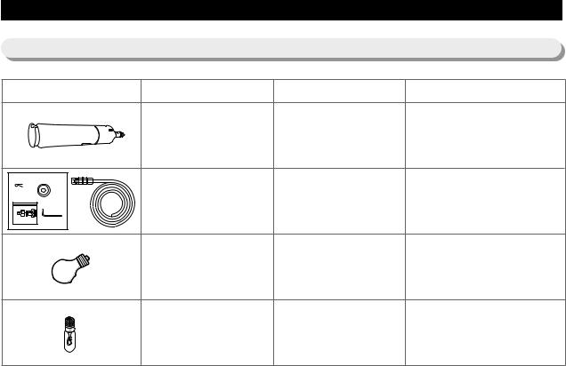
2-6) Optional Material Specifications
Photograph |
Part Name |
Part Code |
Remarks |
|
FILTER |
DA29-00012A |
|
|
WATER-ASSY |
|
|
|
|
|
ASSY-INSTALL
DA97-01469D
FILTER
Refrigerator : 3pcs INCANDENT LAMP 4713-001194 Freezer : 2pcs
120V, 40W
CF : 1pcs INCANDENT LAMP 4713-001172 CR : 1pcs
130V, 30W
12
3. OPERATING INSTRUCTIONS & INSTALLATION
3-1) Digital Panel........................................................................................... |
14 |
||
3-2) Temperature Control Operation ............................................................. |
14 |
||
3-3) Power Freeze and Vacation Operation................................................... |
15 |
||
3-4) Lock Function ....................................................................................... |
16 |
||
3-5) Functions Where the Ice Dispenser and Water Dispenser Have Been |
|
||
Attached (External Type)............................................................................... |
16 |
||
3-6) |
Light Operation ...................................................................................... |
17 |
|
3-7) |
Machine Room F-Fan Motor Delay Function........................................ |
17 |
|
3-8) |
Ice Maker Function ................................................................................ |
18 |
|
3-9) |
Defrosting Function................................................................................ |
22 |
|
3-10) Arctic Select Zone Function................................................................. |
23 |
||
3-11) Select Fresh Zone Function.................................................................. |
23 |
||
3-13) Alarm Function .................................................................................... |
26 |
||
3-14) Communication Error Display Function.............................................. |
26 |
||
3-15) |
Self-Diagnostics Function.................................................................... |
27 |
|
3-16) |
Load Condition Display Function........................................................ |
31 |
|
3-17) |
Operation Condition Recovery Function in Case of Power Outage .... |
32 |
|
3-18) |
Option Setting Function ....................................................................... |
32 |
|
OPERATING INSTRUCTIONS & INSTALLATION
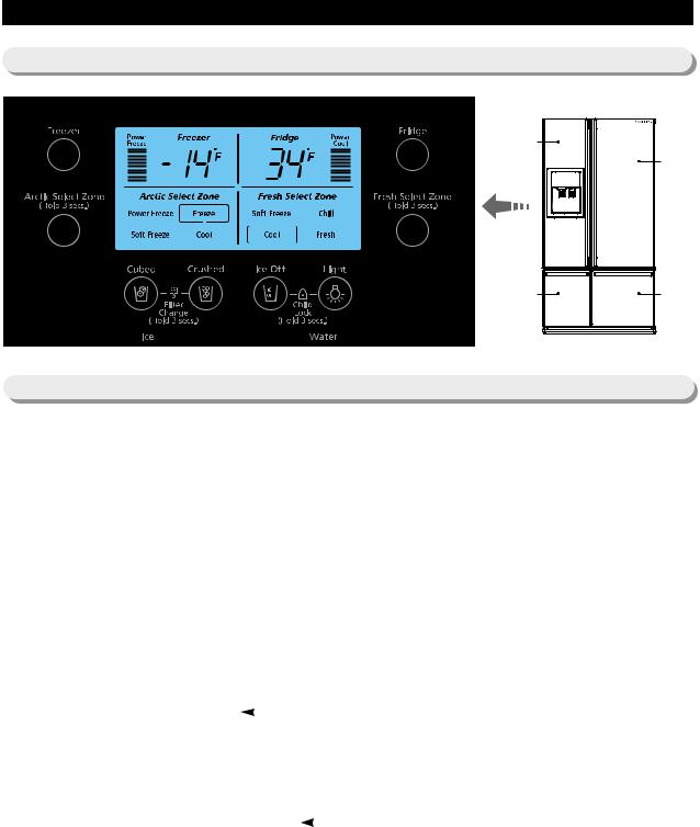
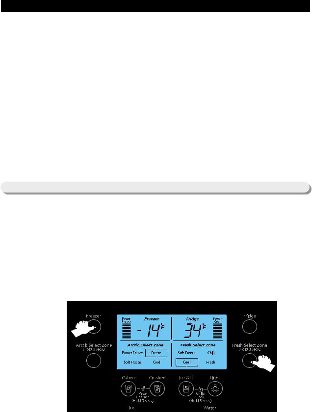
3-1) Digital Panel
Freezer |
|
|
Fridge |
Arctic Select Zone |
Fresh Select |
(CF) |
Zone (CR) |
3-2) Temperature Control Operation
1)Temperature Selection for the Freezer Compartment
1-1) There are automatic temperature asettings of -2 for the freezer compartment and 38 for the fridge compartment
when initially applying electric power after installing refrigerator.
The numbers on the display represent the inside temperature of the refrigerator product. when the set temperature and the displayed temperature are diffrent from each other, it will be automatically adjusted to the
|
|
set temperature. (actual display range of temperature : 15 |
~ 80 |
for the fridge compartment and –25 ~80 |
|||||||||||
|
|
|
for the freezer compartment) |
|
|
|
|
|
|
|
|
||||
|
|
when the freezer temperature is set, it will display the set temperature for the first 5 seconds. and then, it will |
|||||||||||||
|
|
display its current temperature. |
|
|
|
|
|
|
|
|
|||||
1-2) The temperature of the freezer compartment may be set to 6 |
~ –14 |
by operating the temperature selection |
|||||||||||||
|
|
button for the freezer compartment. |
|
|
|
|
|
|
|
|
|||||
|
|
-2 |
-4 |
|
|
-14 |
Power Freeze 6 |
8 |
-2 |
|
Selected in rotating sequence |
||||
|
|
|
|
||||||||||||
|
|
|
|
|
|
|
|
|
|
|
|
||||
2) Temperature Selection for the Refrigerator Compartment |
|
|
|
|
|
|
|
||||||||
2-1) The temperature of the refrigerator compartment may be set to 46 |
~ 34 by operation the temperature |
||||||||||||||
|
|
selection button for the refrigerator compartment. |
|
|
|
|
|
|
|
||||||
|
|
(Example: |
|
38 |
36 |
34 |
Power Cool |
46 |
44 |
…. |
38 ) |
|
|
||
|
|
|
|
|
|||||||||||
|
|
|
|
|
|
|
|
|
|
|
|
|
|
|
|
2-2) Temperature that has been set for the freezer compartment/ the refrigerator compartment may vary by a little difference depending on ambient temperature and user’s food storage style. (Take heed because if food would contact too closely with refrigerator temperature sensor position, then under cooling overcooling may arise as
Note) If temperature in the freezer compartment is lower than 41 (when electric power is supplied again after momentary electricity interruption / when electric power had been cut off for a short time by unstable electric supply because of electricity supply line problem so as to be connected again, then the refrigerator judges it as momentary power interruption. So the refrigerator reads again to use them after saving the temperatures and the functions that had been set in EEPROM
16
14

OPERATING INSTRUCTIONS & INSTALLATION
3-3) Power Freeze and Power cool Operation
1)Power Freeze Operation
1-1) Select 'Power Freeze' by pressing the freezer compartment button. If 'Power Freeze' function is selected, icon display immediately changes to show the newly selected condition but actual function starts to operate after 10 seconds. Where if 'Power Freeze' function is terminated by reselecting the ordinary freezer compartment button during performance of 'Power Freeze' selection, then icon turns off simultaneously with button input as well as 'Power Freeze' function is instantly terminated.
1-2) If power freeze is selected, the COMP and F-FAN operate continuously for 2 hours and 30 minutes.
1-3) The refrigerator compartment operates per the current set condition even during power freeze operation.
1-4) When power freeze is terminated, ICON signifying the power freeze turns off automatically and operation there is by temperature ordinarily set for the freezer compartment. This temperature ordinarily set for the freezer compartment when power freezing operation has been terminated is automatically set at -2
1-5) Even if the condition to start defrosting has been met while the power freezing is in progress, defrosting is delayed until termination of power freezing. If power freezing is selected during defrosting , the ICON turns on readily but the COMP and F-FAN turn on only after defrosting is terminated.
2)Power cool Operation
2-1) If power cool is selected by pressing the fridge compartment button, icon display is lighted and the operation is executed. If power cool is canceled by using the fridge compartment button, the icon is extinguished simultaneously and the well as power cool operation is terminated instantly.
2-2) The temperature setting of the freezer compartment is feasible even under the condition where power freezing has been selected.
2-3) If power cool is selected, COMP and R-FAN operate continuously until the fridge compartment temperature drops down to 24.8 When the function automatically terminates if the continuous operation time reaches 2 hours 30 minutes.
2-4) If the fridge compartment temperature reached 24.8 power cool function terminates after operation for 1 hour at
33.8by in inside function irrespective of current setting.
2-5) Icon of power cool is automatically extinguished at time point when power cool function is terminated (namely either after elapse of 2 hours 30 minutes or after termination of operation for 1 hour at 33.8 from time point of arriving at 24.8 ) and afterwards operation is according to temperature ordinarily set for the fridge compartment. (The fridge compartment is converted to the setting of 37.4 when power cool function is automatically terminated.)
2-6) Control may vary according to various variables (temperature setting etc.) besides the above conditions.
3) If Power Freezing and Power cool Have Been Selected Simultaneously
3-1) The respective functions apply simultaneously. Namely the power freezing operates the COMP. and F-FAN continuously without restriction to the power cool function, while this power cool function operates the COMP and R- FAN continuously until the Fridge Compartment temperature drops down to 24.8 .
17
15

OPERATING INSTRUCTIONS & INSTALLATION
4) At Initial Power On
4-1) At initial power on of fridge product when temperature in the freezer compartment is not lower than 14 and temperature in the fridge compartment is not lower than 50 , if power freezing and power cool functions are selected, operation will be different from the above functions.
4-2) In this case, R-FAN turns off for a little while if power freezing is selected whereas F-FAN turns off for a little while if power cool is selected. This operation works only once at time of initial power on.
4-3) This function is to powerfully cool down only the ROOM preferably wanted by customer when using fridge product for first time while temperature in product would be rather high.
3-4) Lock Function
The lock function is set and canceled by the ICE-OFF and the LIGHT BUTTONS.
-Lock function is set if ICE-OFF BUTTON and LIGHT BUTTON are simultaneously depressed for 3 seconds under lock cancellation status.
-If the lock function has been set, then the ice selection function, functions related to the dispenser, and all other functions are to be held because temperature control / power functions / Arctic Select Zone function / Fresh Select Zone function / ice selection function etc. maintain their current setting conditions. (when the lock LED is on.) This function has been developed to prevent random operation by children (infants).
-If to cancel lock function under condition where lock function has been selected, then lock function may be relieved if ICE-BUTTON and LIGHT BUTTON are simultaneously depressed for 3 seconds so as to be
able to operate on front panel.
If the lock function has been canceled, the lock LED turns off and you may perform key selection. We recommend you to use lock function for user's necessity, and to be well acquainted with it in advance because this function may bring about customer's NON-SENSE CALL.
3-5) Functions in Case Where Ice Dispenser and Water Dispenser Have Been Attached (External Type)
This function applies only for model where ice maker and ice/water dispenser have been attached.
1)CUBE / CRUSHED / ICE OFF Selection Function
1-1) This function is to operate in CUBE/ CRUSHED / (ICE OFF function according to selection upon DISPLAY by user, which selection is made use by each corresponding button.
1-2) CRUSHED is automatically selected at initial POWER ON of the refrigerator product.
1-3) Water is extracted by operating the WATER SOLENOID VALVE under the condition of WATER LEVER ON. 1-4) Operate by using AUGERMOTOR and cubic ice solenoid the ice that has been made in ice tray when drawing
out ice after selecting the CUBE.
1-5) Operate by using only AUGER MOTOR the ice that has been made in ice tray when drawing out ice after selecting the CRUSHED .
1-6) ICE-MAKER stops operation if function of ICE OFF has been selected. After if cubic / crushed are selected, function of ice off is automatically halted so as to facilitate again execution of ice maker function that was in use before ice off.
18
16

OPERATING INSTRUCTIONS & INSTALLATION
=> ICE-MAKER stops operation if function of ICE OFF has been selected. After if cubic / crushed are selected, then water is supplied. If cubic / crushed are selected, now you can be promptly provided with ice only that was already formed before selecting ice off.
1-7) When drawing out ice, this is extracted after DISPENSER SWITCH is depressed and ICE COVER is completely opened.
1-8) ICE COVER is shut after 5 seconds from time point when DISPENSER SWITCH turned off after drawing out ice. 1-9) If DISPENSER SWITCH turned ON or WATER SWITCH turned ON, DISPENSER LAMP is lighted but turns off after 5 seconds from time point when DISPENSER SWITCH and WATER SWITCH would have turned OFF.
Caution : because if ice cover is coercively closed then it may be damaged, please draw out ice once again if ice cover would not be closed, so that the cover operate rationally.
Note) When drawing out ice after selecting the ice stop, only the ice remaining in ice tray may be drawn out. And even when ice stop has been selected, cubic / crushed may be used restricted to the remaining ice.
2)Water Dispenser Function
2-1) As this function is type of direct connection to water, it works so that water is extracted by opening of water solenoid valve installed at right side of machine compartment if water lever is depressed. If abnormality occurred in water dispenser function, repair it by checking solenoid itself, connection tube, water supply status etc.
3-6) Light Operation
6-1) This function is selected or canceled by light selection button.
6-2) If the light button is selected under light cancellation status, the LIGHT LED and the DISPENSER LIGHT turn on. 6-3) If the WATER SWITCH or the DISPENSER SWITCH is turned on, under the condition of light cancellation status, the
DISPENSER LIGHT turns on.
6-4) Under the condition of light function selection, the LIGHT LED and the DISPENSER LIGHT are always turned on regardless of WATER SWITCH and DISPENSER SWITCH operation conditions.
3-7) Machine Room F-Fan Motor Delay Function
The temperature in this refrigerator is automatically controlled by program depending on ambient temperature. Among the operative functions depending on ambient temperature, the compressor cooling fan (machine room fan) is controlled as shown in the table below. Accordingly, in case that cooling fan may revolve with delay or may not revolve at all according to conditions when operating the compressor, please be acquainted with details and refer to them during service.
|
Temperature Range |
Load Operation Condition |
Machine Room |
Exterior temperature 46.4 |
Machine room fan is immediately tuned on as the compressor is ON. |
|
|
|
Fan Delay Function |
|
|
Exterior temperature 44.6 |
Machine room fan is OFF regardless of the compressor. |
|
|
|
|
19
17
OPERATING INSTRUCTIONS & INSTALLATION
3-8) ICE-MAKER Function (applies only for model with dispenser function)
This ICE-MAKER function is option specification so as to be drawn to the function explanation for relevant model.
ICE-MAKER is model attached with unit equipment where is furnished function of automatic ice making so that ice may be made in container inside the freezer compartment and may be drawn out by using ice dispenser under storage status ==> The equipment.
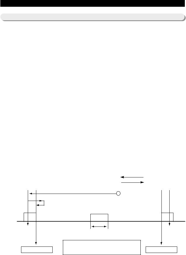
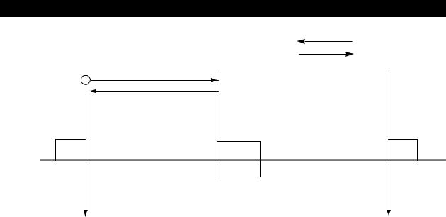
1) Initial Operation
This is operation at initial “power on” or at that after “power off” due to electricity interruption which operation is to restore to horizontality by revolving ice extraction motor.
1-1) At first no operation is performed for 2 seconds after initial power on or after power returns after a momentary power outage. But after that, an initial horizontality operation of the ice extraction is performed.
2-1) Because the condition of the ice maker is unknown, first the ice extraction motor is turned in the reverse direction to let it come to its most horizontal position possible. The judgment of horizontal position is done by the ice extraction S/W. If this S/W is on for more than 2 seconds during the reverse rotation of the ice extraction motor, then it is judged that the transition to the most horizontal position possible has been made and the ice extraction motor is stopped (1). It waits a second in this condition.
3-1) Because condition 2-1) is an upset twisted condition caused by the reverse direction rotation of 2 seconds after sensing the horizontal position, the motor revolves in the forward direction for 200 ms after ice tray S/W off (2) and then It waits 1 second.
4-1) Finally to achieve horizontality, the ice tray motor turns again in the reverse direction but it will stop immediately if the ice tray S/W comes on (3), which condition may be interpreted as the horizontal
5-1) The standby condition is maintained for 2 hours regardless of any conditions after Ice-Tray horizontality operation. Therefore, under the initial power on condition, there is no movement for 2 hours except for the ice tray horizontality operation.
6-1) Ice is made if the ice making temperature has been reached according to the ice tray temperature check after a 2 hours wait period (initial ice extraction mode).
Reverse rotation : CCW
Forward rotation : CW
(1)
(2)
(3)
Ice extraction
S/W
Signal generated by ice inspection lever when returning to horizontal position
Instrumental
lock position
Horizontal position
Interval about 880ms
S/W cognition debounce is taken about 2 seconds at time of reverse rotation of interval (1) so as not to mistake this interval as horizontal position
Instrumental lock position
Maximum torsion point
FigureHorizontal movement operation at initial power on of the product (referes to ice extraction S/W)
20
18

OPERATING INSTRUCTIONS & INSTALLATION
2)Water Supply Function
2-1) After finishing the ice extraction operation (initial ice extraction operation, normal ice extraction operation and ice extraction operation of test function) and performing the ice receptacle horizontality operation, if it is judged to have attained horizontality, then there is executed operation of water solenoid located in refrigerator machine compartment for time check function so as to supply water into the ice maker receptacle.
Model |
Water Supply Time |
Remark |
|
|
|
Model furnished with |
Cf. OPTION function & |
It may be altered by OPTION function and water supply rate may vary |
ice-maker function |
FLOW_SENSOR function |
depending on water pressure since it is connected directly to the |
option |
|
water source. |
|
|
|
3) Ice-Making Function
Here is referred to period until it is opined that water in ICE -TRAY(ice maker vessel) has completely become ice after finishing the water supply operation, which period is judged by sensed temperature (which is alterable option) of ice maker sensor.
3-1) The ice maker sensor temperature is automatically checked after 58 minutes have elapsed (65 minutes in case of overload) from the time when water was supplied into the ice maker receptacle.
3-2) If the ice maker sensor maintains below stays 1.4 for 5 minutes, then it is judged that the ice making cycle has been completed.
3-3) In case of initial electric power application to the product or in case of recovery from a power outage, the ice extraction is operated after waiting 2 hours, not detaching the ice after checking the the ice maker sensor even though the temperature may be checked to have reached below 1.4
Note) While it is not full of ice is not fully frozen or when ICE OFF has not been selected, it operates internally at -13. until it becomes full of ice (until the ice tray is of ice). As soon as full ice is achieved, the freezer compartment temperature is automatically controlled at the temperature set by the customer.
4) Ice Extraction Function
The ice extraction function is to separate the ice in the ice extraction (ice maker vessel) after completing the ice making process. This function is achieved by operating in accordance with to the following steps. These operations are classified into full ice case and non-full ice case according to the
ice extraction S/W condition variation: |
|
|
|
||||
|
Full ice case : step 1 |
step 2 |
step 3 |
step 4 |
step 5 |
step 6 |
|
|
Non-full ice case : step 1 |
step 2 |
step 6 |
|
|
|
|
4-1) Step 1: this is stage to check firstly the ice making temperature in order to perform ice extraction where check is performed both if the current ice making temerature is below 1.4 and if 90 minutes (55minutes in case of power freezing) have elapsed after water supply.
-If the F compartment enters defrosting while waiting for ice tray, counting is restarted from 0 after defrosting is completed so that the check is performed if the ice extraction waiting (58 minutes) has elapsed after defrosting
the F compartment. The ice maker temperature sensor enters step 2 if 5 minutes pass after going below 1.4 .
19
OPERATING INSTRUCTIONS & INSTALLATION
4-2) Step 2 : operation is to overturn tray in order to separate the ice in the ice tray where tray is overturned by direction rotation of ice extraction motor.
-In case the storage container is full ice: if the ice extraction S/W is ON again before 3.6 seconds elapse from the time the extraction S/W condition changed to “on off” has occurred after starting rotation of the ice extraction motor, then this means that the storage tray is full of ice so that direction rotation of the motor is interrupted so as to start reverse direcion rotation (horizontal movement) after waiting a second. Step 6 is executed.
- In case the storage is not full ice: if the ice extraction S/W is not ON again after 3.6 seconds from the time when the ice extraction S/W condition changed to “on off” has occurred after starting rotation of the ice extraction motor, then this is judged to mean that it is not full of ice, in which case normal ice extraction movement is performed and step 3 is executed.
4-3) Step 3 : if the ice extraction S/W is not ON again after 3.6 seconds from the time when the ice extraction S/W condition changed to on “on off” has occurred after starting rotation of the ice extraction motor, then this is judged to mean that it is for normal ice extraction operation. If F compartment door is opened during ice extraction operation thereafter, operation stops for a while and restarts after Door Close.
4-4) Step 4 : motor rotation stops if the ice extraction S/W turns on after 3.6 seconds have elapsed from the start of the rotation. This point is the maximum torsion point and waits a second under this condition.
4-5) Step 5 : It is a step that ice extraction restores horizontally accomplished by reverse rotation of ice extraction motor. So after step 4, the ice extraction motor turns in the reverse direction when the ice extraction S/W always senses the full ice lever signal regardless of the ice existence of the ice storage container so as to be called the "Return Pulse".
4-6) Step 6 : if the ice extraction S/W turns ON after the "Return Pulse, the reverse rotation of the ice extraction horizontally motor stops and the ice extraction is judged to be in the horizontal position. If now it has been restored horizontally after sensing full ice, water is not supplied but ice extraction is retried consecutively in 1 hour intervals until full ice cancellation. So thereafter, water is supplied if normal ice extraction has been performed.
4-7) Figure shows operation specification of ice extraction (in case of non full ice / full ice). |
|
|
|||
(bold numerals indicate relevant ice tray steps.) |
|
|
Reverse rotation : CCW |
||
(1) |
|
|
|
Forward rotation : CW |
|
|
(2) |
(3) |
|
(4) |
|
|
|
||||
(6)
(5)
Return Pulse
Ice extraction S/W
Return Pulse in case of non-full ice
:doesn`t - occur during forward direction rotation
:occurs at reverse direction rotation
Horizontal position |
|
Maximum torsion point |
|
|
|
Figure - Normal ice extraction and horizontality operation (in reference to the ice extraction S/W)
20
OPERATING INSTRUCTIONS & INSTALLATION
Reverse rotation : CCW
Forward rotation : CW
(1) |
(2) |
|
|
(6) |
|
Return Pulse
Ice extraction S/W
Return Pulse in case of full ice
: occurs at forward direction rotation
Horizontal position |
|
Maximum torsion point |
|
|
|
Figure - ice extraction and horizontality operation in case of full ice (in reference to the ice extraction S/W)
5) Test Function
This function is useful when there is a need for forced operation for testing purposes, A/S, cleaning etc. This function is executed when the test S/W attached to the automatic ice maker itself is pressed for more than 1.5 seconds.
5-1) The test function by pressing test button cannot be engaged during ice extraction, horizontality noise or water supply operation but can operate when in the horizontal condition. Also, the test function cannot operate when ice is full. The operation is only feasible when full ice has been relieved..
5-2) If the test button is pressed for more than 1. 5 seconds in horizontal status, the ice extraction is operated directly regardless of the ice making condition of the ice maker container. Beware that water pours out if test function operates with unfrozen water. 1 cycle of water supply is executed at the horizontal noise operation after the ice transfer operation. Therefore it is feasible to check ice extraction operation, horizontality operation and water supply problems by using the test button. When the test function is normally executed, the buzzer sounds “ding dong” and the water supply function is executed. If buzzer does not sound "ding-dong", it signifies abnormality so check and repair is needed.
5-3) If the water supply has finished, it then goes through a normal cycle of ice making |
ice extraction |
|
horizontality operation |
water supply again. |
|
6) ICE OFF Function
Ice making can be stopped by pressing the ice selection button to select ICE OFF when either ice is not wanted or its use is not needed.
6-1) ICE OFF is selected if the ice selection button is pressed on the DISPLAY and ICE OFF is canceled if the button is pressed again.
6-2) When the electric power turns on, the refrigerator operates automatically in the ice making mode where fragment ice is automatically selected and the lamp is lit.
6-3) If you want to, ICE OFF is selected by using the ice selection button, then the ice maker does not operate and it maintains the stop condition.
21

OPERATING INSTRUCTIONS & INSTALLATION
6-4) Display lamp is directly extinguished right at the stop selection, but it maintains stop condition after the completion of final water supply if water supply, ice extraction or horizontality noise is under progress.
7) At test operation by test key, ice tray operates regardless of F compartment door opening.
This function basically stops the operation if the F compartment door is opened , so that noise may be minimized.
7-1) The ice extraction function promptly stops the operation when the F compartment door is opened while the ice extraction is working where as normal operation is restored when the door is closed.
7-2) During water supply, normal function is performed regardless of the F compartment door opening.
7-3) When checking by opening the F compartment door, if the extraction has been tilted or is not horizontal, it is a stop condition during ice extraction or horizontality operation because of the F compartment door opening. Then check again after more than 30 seconds elapse from the time when the F compartment door closed to ensure a horizontal condition after the water supply operation, if the extraction has not restored its horizontal status, it is ok to judge it to be a trouble/ failure. When operation stops by the F compartment door opening during (ice extraction) operation, because it has been during actual operation, even the test function does not work, but it may work after water supply completion.
=> When checking by opening the F compartment door during ice extraction or horizontality operation, if the tray i tilted or distorted , it is a stop condition because of F compartment door opening. Then check again after more than 30 seconds have elapsed from time when the F compartment door closed, if the tray has not restored its horizontal status, it is ok to judge it to be a trouble/ failure. When operation stops by the F compartment door opening during ice extraction operation, because it has been during actual operation, even the test function does not work.
7-4) During test operation by using the test key, the ice extraction operates regardless of F compartment door opening.
3-9) Defrosting Function
1)Defrosting of the F compartment, Arctic Select Zone, R compartment and the Fresh Select Zone is determined by the cumulated time period of COMP. ON.
2)In case of initial POWER ON of the refrigerator product, defrosting of the Freezer Compartment and Arctic Zone is executed when 4 hrs. of cumulated COMP. ON time period have elapsed.
3)The defrosting period is fixed to 8 hours.
4)Judgment of the defrosting period is determined by the exterior temperature, the number of times the F, R DOOR OPEN, and the duration of the F, R DOOR OPEN period.
5)The defrosting point temperature HEATER ON (start temperature) is determined by the temperature reading of the R defrosting sensor, the F defrosting sensor, the Artic Zone defrosting sensor and the Fresh Zone defrosting sensor as follows:
|
R |
F |
Arctic Zone |
|
|
|
|
|
|
Fresh Zone |
Remarks |
||
|
Compartment |
Compartment |
Other Setting |
When Setting to COOL |
||
|
|
|
||||
Defrosting Recovery |
53.6 |
53.6 |
53.6 |
62.6 |
62.6 |
|
Temperature |
|
|||||
|
|
|
|
|
|
|
Note) The defrosting recovery temperature may be changed at any time, for performance improvement etc..
22

OPERATING INSTRUCTIONS & INSTALLATION
3-10) Arctic Select Zone Function
1)Arctic Select Zone is set to Freeze at initial POWER ON.
2)The function is set and changed as follows by pressing the Arctic Select Zone button.
|
|
Freeze |
|
|
Soft Freeze |
|
Cool |
|
|
Power Freeze |
|
|
|
|
|
|
|
|
|
||||
|
|
|
|
|
|
|
|
|
|
|
|
|
|
|
|
|
|
|
|
|
|
|
|
3)If pressing the button for initial setting of Arctic Select Zone for 3 seconds, buzzer sound is heard and simultaneously Arctic and Fresh Select Zones are converted to a function setting mode.
4)If the Arctic Select setting button is pressed again, in the function setting mode, the function setting is sequentially changed as in item 2 above).
5)The function setting mode is canceled when 10 seconds have elapsed after pressing the button and entering the Arctic function setting mode.
6)The Arctic Select Zone function operates as follows.
FUNCTION |
OPERATION SPECIFICATION |
|
REMARKS |
|
|
|
|
|
|
Freeze |
Interlocked with the set temp. (5 |
~ -13 |
) of the |
|
freezer compartment |
|
|
||
|
|
|
||
|
|
|
|
|
Soft Freeze |
Arctic Select Zone, 23 |
operation |
|
|
|
|
|
|
|
Cool |
Arctic Select Zone, 37.4 |
operation |
|
|
|
|
|
||
Power Freeze |
- IIf this function is selected, it operates continuously for 2 hours and 30 minutes. |
|
||
- If this function finishes automatically, it is automatically converted to Freeze. |
|
|||
|
|
|||
|
|
|
|
|
3-11) Fresh Select Zone Function
1)At initial POWER ON of the refrigerator, the Fresh select Zone is set to Cool.
2)This function is set and changed as follows by pressing the Select Fresh Zone button.
|
|
Cool |
|
|
Fresh |
|
Soft Freeze |
|
|
Chill |
|
|
|
|
|
|
|
|
|
||||
|
|
|
|
|
|
|
|
|
|
|
|
|
|
|
|
|
|
|
|
|
|
|
|
3)If initially the button to set the Fresh select Zone is pressed for 3 seconds, the buzzer sounds, and at same time, the mode is converted to the Arctic and Fresh Select Zones function setting mode.
4)If the Fresh Select setting button is pressed again, in the setting mode, function setting is sequentially changed as in item 2 above).
5)The function setting mode is canceled after 10 seconds have elapsed from pressing the button to Fresh Select Zone.
6)Fresh Select Zone function operates as follows.
23
OPERATING INSTRUCTIONS & INSTALLATION
FUNCTION |
OPERATION SPECIFICATION |
REMARK |
|
|
|
|
|
Cool |
Fresh Select Zone temp. is controlled by interlock with the set |
|
|
temp. (33.8 ~ 44.6 ) of the Fridge compartment |
|
||
|
|
||
|
|
|
|
Fresh |
Fresh Select Zone, 37.4 |
operation |
|
|
|
|
|
Soft Freeze |
Fresh Select Zone, 23 |
operation |
|
|
|
|
|
Chill |
Fresh Select Zone, 30.2 |
operation |
|
|
|
|
|
3-12) Test Functions (Forced Operation Start and Forced Defrosting Functions)
If the Fresh Select Zone key and the F compartment key on the PANEL PCB are simultaneously pressed for more than 8 seconds, then the TEST MODE is entered. Now, whether the F compartment key, the R compartment key, the Arctic Select Zone key or the Fresh Select Zone key is pressed, it operates as a TEST KEY.
If a TEST KEY is pressed, the test function is changed in sequence to forced operation start (FF) forced
R, CR defrosting |
forced R, CR,F, CF defrosting |
test cancellation (normal operation) |
forced |
operation start. |
|
|
|
To cancel the function during test function operation, it is the most desirable way to turn on the power again after turning it off.
24

OPERATING INSTRUCTIONS & INSTALLATION
1)Forced Start Operation Function
1-1) Forced start operation is selected if the test key is pressed once while in the test mode. At that time the buzzer executes an alarm by making a beep sound.
2-1) If forced start operation is selected , then COMP. operates immediately without a 5 minute delay, regardless of operating mode. If it is during defrosting, defrosting shall promptly stop.
3-1) If forced start operation is selected, then the COMP. and F FAN perform a PULL-DOWN operation for 24 hours while the R compartment is controlled by the set temperature.
4-1) The forced start operation is performed continuously performed until completed, canceled or converted to an other mode (forced F, R, CF, CR defrosting).
5-1) If the forced start operation is selected , then along with it, a automatic selection is made for the F compartment
”-13 |
and for the R compartment “33.8 |
These settings are not changed (maintains “-13 |
and “33.8 |
) |
||
even if forced defrosting or test cancellation is selected after more than 1 minute elapses under the condition |
|
|||||
where forced start operation has been selected Nevertheless the setting are restored to the temperatures that |
||||||
were set before the change to ”-13 |
and “33.8 |
if forced defrosting or test cancellation is selected before 1 |
||||
minute elapses from the time when the forced start operation was selected.
6-1) If forced start operation is finished(24 hours), then F, CF compartment defrosting is executed regardless of previous condition.
7-1) Next, it proceeds normal defrosting opera according to CASE judgment, performing defrosting of the R compartment defrosting.
8-1) If randomly canceled during forced start operation (by cancellation mode), the COMP. ON time period during the forced start operation is also added to the accumulation to be considered for the defrosting period.
9-1) The power freezing and power refrigeration functions do not work during forced start operation. If any of these functions is selected, the LED display for the selected POWER function turns off spontaneously after approximately 10 seconds..
2)Forced Defrosting Function
1-1) If test button is pressed a second time, then R compartment / CR compartment defrosting is executed, and if the test button is pressed a third time, then simultaneous defrosting of F, CF, R, CR compartments is executed, and a beeping sound alarm is also executed.
2-1) The beeping sound alarm is executed until completion time of the heating and pause time.
3)Test Cancellation Mode
3-1) If the display panel is converted to the test mode and the test button is pressed once more, under the simultaneous defrosting condition, then defrosting of freeze and refrigeration partitions is canceled simultaneously to return to normal operation. Or if main power is turned on after turnoff, then all test functions are canceled.
25

OPERATING INSTRUCTIONS & INSTALLATION
3-13) Alarm Function
1)Button Touch Sound (Refer to Sounds Table)
1-1) When touching each button on the control panel, an input confirmation sound is generated (see the following table), according to each operating condition.
Description |
Sound Group |
Sound Pattern |
When selecting power freezing / power refrigeration / |
SUB ON |
|
lock / stop icing / Filter Reset / light |
(Function Selection) |
|
When canceling power freezing / power refrigeration |
SUB OFF |
|
/ lock / stop icing / light |
(Function Cancellation) |
|
|
|
|
When selecting the cube ice / crushed ice |
MODE |
|
When selecting the Arctic Select Zone function |
(Function |
|
When selecting the Fresh Select Zone function |
Change "Ding") |
|
|
|
|
When selecting the refrigerator compartment / freezer |
VERTICAL |
|
compartment |
(Temperature Setting) |
|
When water supply is finished, in the ice maker test mode |
Ding Dong Sound |
ExistingDingDongSound |
Door-open alarm sound |
ALERT(Warning Sound) |
|
1-2) If several plural buttons are pressed simultaneously or in case of wrong button operation, an input confirmation sound is not generated.
2)DOOR-OPEN Alarm Sound
2-1) If F compartment, R compartment, Arctic Zone, or Fresh Zone door remains open for 2 minutes in row, alarm sound is generated by 10 times.
2-2) If the door open condition is maintained even longer, the operation recycles generating the alarm sound 10 times per 1 minute period.
2-3) The alarm sound stops readily if the refrigerator compartment and the freezer compartment are both closed.
3-14) Communication Error Display Function
1) Display Function at PANEL |
MAIN MICOM Communication Error |
1-1) If 10 seconds elapse without response, after transmission of a communication request from the PANEL MICOM, the PANEL PCB repeats ON/OFF until the communication error is cleared (by repeting ALL ON for 0. 5 second and ALL OFF for 0. 5 second).
2) Display Function at MAIN |
LOAD MICOM Communication Error |
2-1) If 10 seconds elapse without response, after transmission of a communication request from the MAIN MICOM to the LOAD [SUB(ORDINATE)] MICOM, then the PANEL PCB DISPLAY repeats ON/OFF until the communication error is cleared (by repeting ALL ON for 0. 5 second and ALL OFF for 0. 5 second).
26
 Loading...