


 Loading...
LCD-TV
Chassis : N82B
Model : LE26C35***
LE32C35***
SERVICE Manual 
TFT-LCD TV |
|
Contents |
|
|
|
1. Precautions
2. Product specifications
3. Disassembly and Reassembly
4. Troubleshooting
5. Exploded View & Part List
6. Wiring Diagram
LE26C35***/LE32C35***
Refer to the service manual in the GSPN (see the rear cover) for the more information.
Contents
1. Precautions............................................................................................................... |
1-1 |
|
1-1. |
Safety Precautions.......................................................................................................... |
1-1 |
1-2. |
Servicing Precautions...................................................................................................... |
1-2 |
1-3. |
Electrostatically Sensitive Devices (ESD) Precautions................................................... |
1-2 |
1-4. |
Installation Precautions................................................................................................... |
1-3 |
2. Product specifications............................................................................................. |
2-1 |
|
2-1. |
Feature & Specifications................................................................................................. |
2-1 |
2-2. |
Specification Comparison to Old Models........................................................................ |
2-3 |
2-3. |
Detail Factory Option....................................................................................................... |
2-4 |
2-4. Accessories..................................................................................................................... |
2-5 |
|
3. Disassembly and Reassembly................................................................................ |
3-1 |
3-1. Disassembly and Reassembly........................................................................................ |
3-1 |
4. Troubleshooting....................................................................................................... |
4-1 |
4-1. Troubleshooting............................................................................................................... |
4-1 |
4-2. Alignments and Adjustments......................................................................................... |
4-25 |
4-3. Factory Mode Adjustments............................................................................................ |
4-26 |
4-4. White Balance - Calibration........................................................................................... |
4-34 |
4-5. White Ratio (Balance) Adjustment................................................................................. |
4-34 |
4-6. Servicing Information..................................................................................................... |
4-35 |
4-7. How To Upgrade Sub Micom With Ddc Manager.......................................................... |
4-36 |
4-8. Mechanical diagram...................................................................................................... |
4-38 |
4-9. PCB diagram................................................................................................................. |
4-39 |
5. Exploded View & Part List....................................................................................... |
5-1 |
5-1. LE26C35*** Exploded View............................................................................................ |
5-1 |
5-2. LE26C35*** Parts List..................................................................................................... |
5-3 |
5-3. LE32C35*** Exploded View............................................................................................ |
5-8 |
5-4. LE32C35*** Parts List................................................................................................... |
5-10 |
6. Wiring Diagram......................................................................................................... |
6-1 |
6-1. Wiring Diagram................................................................................................................ |
6-1 |
6-2. Connector........................................................................................................................ |
6-2 |
6-3. Connector Functions....................................................................................................... |
6-4 |
6-4. Cables............................................................................................................................. |
6-4 |

GSPN (Global Service Partner Network)
Area |
Web Site |
|
|
North America |
http://service.samsungportal.com |
|
|
Latin America |
http://latin.samsungportal.com |
|
|
CIS |
http://cis.samsungportal.com |
|
|
Europe |
http://europe.samsungportal.com |
|
|
China |
http://china.samsungportal.com |
|
|
Asia |
http://asia.samsungportal.com |
|
|
Mideast & Africa |
http://mea.samsungportal.com |
|
|
This Service Manual is a property of Samsung Electronics Co.,Ltd.
Any unauthorized use of Manual can be punished under applicable International and/or domestic law.
© 2010 Samsung Electronics Co.,Ltd. All rights reserved.
Printed in Korea P/N: BN82-00744A-00

3. Disassembly and Reassembly
3. Disassembly and Reassembly
This section of the service manual describes the disassembly and reassembly procedures for the LE32C35*** LCD TV.
 WARNING: This LCD TV contains electrostatically sensitive devices. Use caution when handling these components.
3-1. Disassembly and Reassembly
Cautions: 1. |
Disconnect the LCD TV from the power source before disassembly. |
|
|
2. |
Follow these directions carefully; never use metal instruments to pry apart the cabinet. |
|
|
|
|
|
|
Description |
Picture Description |
Screws |
|
1.Place the TV face down on cushioned table. Remove 8 screws from the back cover.
6002-001294
(M4, L16,Tapping)
2.Lift up the rear cover.
Remove the 3 screws of main board and 4 screws of IP board.
6003-001188
(M4, L10, TAPTYPE)
3. Remove 4 screw.
6003-001188
(M4, L10, TAPTYPE)
4. Remove 6 screws.
6002-001294
(M4, L16,Tapping)
3-1

3. Disassembly and Reassembly
Description |
Picture Description |
Screws |
5. Lift up the panel.
Reassembly procedures are in the reverse order of disassembly procedures.
3-2

5. Exploded View & Part List
5. Exploded View & Part List
5-1. LE26C350D1W Exploded View
R001A
P001A
PANEL
M0014
T0003
T0175
M0027
T0175
5-1

5. Exploded View & Part List
5-1-1. LE26C350D1W Parts List
Location No. |
Code No. |
Description & Specification |
Q’ty |
S.A/S.N.A |
Remark |
|
|
|
|
|
|
F001A |
BN96-12858B |
ASSY COVER P-FRONT;LC350 26,EO,PC+ABS,V0 |
1 |
SA |
|
|
|
|
|
|
|
M0014 |
BN94-02670A |
ASSY PCB MAIN;LC350,N82B |
1 |
SA |
|
|
|
|
|
|
|
P001A |
BN44-00368B |
AC VSS(I)-TV;I26HD_AHS,I26HD_AHS,11mA,12 |
1 |
SA |
|
|
|
|
|
|
|
PANEL |
BN07-00866A |
LCD-PANEL;T260HA01-DB,CLC3AC1,8bits,26,1 |
1 |
SA |
|
|
|
|
|
|
|
R001A |
BN96-12866A |
ASSY COVER P-REAR;LC350 26,EO,HIPS,V0,BK |
1 |
SA |
|
|
|
|
|
|
|
SB04A |
BN96-12869B |
ASSY STAND P-BASE;LC350 26,PC+ABS,V0,BK0 |
1 |
SA |
|
|
|
|
|
|
|
T0175 |
BN96-13058A |
ASSY SPEAKER P;16ohm,4pin,5W,L:600 R:150 |
1 |
SA |
|
|
|
|
|
|
|
5-2

5. Exploded View & Part List
5-2. LE26C350D1W Parts List
Service Bom (SA: SERVICE AVAILABLE, SNA: SERVICE NOT AVAILABLE)
Level |
Location No. |
Code No. |
Description & Specification |
Q’ty |
SA/SNA |
Remark |
|
|
|
|
|
|
|
0.1 |
|
BN90-02519B |
ASSY COVER FRONT;LC350 26 |
1 |
SNA |
|
|
|
|
|
|
|
|
..2 |
F001A |
BN96-12858B |
ASSY COVER P-FRONT;LC350 26,EO,PC+ABS,V0 |
1 |
SA |
|
|
|
|
|
|
|
|
...3 |
M0081 |
6003-001024 |
SCREW-TAPTYPE;RWH,+,B,M4,L12,ZPC(WHT),SW |
4 |
SNA |
|
|
|
|
|
|
|
|
...3 |
T0069 |
BN60-00048A |
SPACER-FELT;50Q9,FELT,620L,BLK,0.35T,10W |
2 |
SNA |
|
...3 |
CCM1 |
BN63-02183F |
COVER-SHEET;Rhcm,PE Vinyl,T0.04,900mm,20 |
0.28 |
SNA |
|
|
|
|
|
|
|
|
...3 |
CCM1 |
BN63-05199P |
COVER-SHEET;AMBER,PE,T0.08,W1000,200M,CL |
0.16 |
SNA |
|
...3 |
F001 |
BN63-06675B |
COVER-FRONT;LC350 26,EO,PC+ABS,V0,BK0008 |
1 |
SNA |
|
|
|
|
|
|
|
|
...3 |
C457 |
BN64-01302A |
WINDOW-REMOCON;32LC350,PC,V0,VIOLET |
1 |
SNA |
|
|
|
|
|
|
|
|
...3 |
T0175 |
BN96-13058A |
ASSY SPEAKER P;16ohm,4pin,5W,L:600 R:150 |
1 |
SA |
|
|
|
|
|
|
|
|
...3 |
M0125 |
BN96-13063B |
ASSY BOARD P-TOUCH FUNCTION&IR;LC350,FR- |
1 |
SA |
|
|
|
|
|
|
|
|
0.1 |
R001A |
BN90-02523D |
ASSY COVER REAR;LC350 26 |
1 |
SNA |
|
..2 |
T0081 |
6002-001294 |
SCREW-TAPPING;BH,+,,M4,L16,ZPC(BLK) |
7 |
SA |
|
|
|
|
|
|
|
|
..2 |
R001A |
BN96-12866A |
ASSY COVER P-REAR;LC350 26,EO,HIPS,V0,BK |
1 |
SA |
|
...3 |
T0069 |
AA60-00091D |
SPACER-FELT;FELT,200X10,BLK,T0.35 |
2 |
SNA |
|
|
|
|
|
|
|
|
...3 |
R001 |
BN63-06694A |
COVER-REAR;LC350 26,EO,HIPS,V0,BK0020 |
1 |
SNA |
|
|
|
|
|
|
|
|
...3 |
T0071 |
BN64-01320A |
INLAY-TERMINAL;LC350,32,PS SHEET,T0.5,BL |
1 |
SNA |
|
|
|
|
|
|
|
|
...3 |
T0139 |
BN65-00002A |
CLAMPER CORE;BORDEAUX,LDPE,BLK |
1 |
SNA |
|
|
|
|
|
|
|
|
0.1 |
S001A |
BN90-02526B |
ASSY STAND;LC350 26 |
1 |
SNA |
|
..2 |
SB04A |
BN96-12869B |
ASSY STAND P-BASE;LC350 26,PC+ABS,V0,BK0 |
1 |
SA |
|
|
|
|
|
|
|
|
...3 |
CCM1 |
BN63-02183D |
COVER-SHEET;Rhcm,PE Vinyl,T0.04,680mm,20 |
0.4 |
SNA |
|
...3 |
|
BN63-06687B |
COVER-STAND BASE;LC350 26,PC+ABS,V0,BK00 |
1 |
SNA |
|
|
|
|
|
|
|
|
....4 |
|
0103-005041 |
RESIN-PC;V0,PC+ABS |
407 |
SNA |
|
...3 |
M0126 |
BN73-00052B |
RUBBER-FOOT;42Q9,c9,CR Rubber Gray,T3.0 |
4 |
SNA |
|
|
|
|
|
|
|
|
0.1 |
M0017 |
BN91-04865A |
ASSY CHASSIS;LC350,N82B |
1 |
SNA |
|
|
|
|
|
|
|
|
..2 |
M0014 |
BN94-02670A |
ASSY PCB MAIN;LC350,N82B |
1 |
SA |
|
...3 |
|
0202-001608 |
SOLDER-WIRE FLUX;LFC7-107,D0.8,99.3Sn/0. |
0.025 |
SNA |
|
|
|
|
|
|
|
|
...3 |
|
3701-001480 |
CONNECTOR-DSUB;15P,3R,FEMAIL,STAMPED PIN |
1 |
SA |
|
...3 |
HB01A |
3711-006715 |
HEADER-BOARD TO CABLE;BOX,4P,1R,2.5mm,AN |
1 |
SNA |
|
|
|
|
|
|
|
|
...3 |
HB01A |
3711-007321 |
HEADER-BOARD TO CABLE;BOX,12P,2R,2mm,STR |
1 |
SA |
|
...3 |
CIS3 |
BN40-00173A |
TUNER;DTOS40CVL081A,DVB-T/C,164CH,38.9MH |
1 |
SA |
|
|
|
|
|
|
|
|
...3 |
|
BN97-00688A |
ASSY HDCP;BN46-00018A,PS-42V6S,D73A,GENE |
1 |
SNA |
|
....4 |
|
BN46-00018A |
KEY CODE-CERTIFICATE;(HDCP KEY)PPM42M5S, |
1 |
SNA |
|
|
|
|
|
|
|
|
...3 |
|
BN97-04022A |
ASSY SMD;LC350,N82B,BN94-02670A |
1 |
SNA |
|
|
|
|
|
|
|
|
....4 |
DS01A |
0401-001056 |
DIODE-SWITCHING;MMBD4148SE,100V,200mA,SO |
9 |
SA |
|
....4 |
|
0403-001180 |
DIODE-ZENER;BZX84C6V2,5.8-6.6V,350mW,SOT |
1 |
SA |
|
|
|
|
|
|
|
|
....4 |
|
0403-001783 |
DIODE-ZENER;BZB84-C6V2,5.8/6.6V,300mW,SO |
13 |
SNA |
|
....4 |
D0254 |
0404-001404 |
DIODE-SCHOTTKY;BAT721C,40V,200mA,SOT-23, |
1 |
SA |
|
|
|
|
|
|
|
|
....4 |
T0139 |
0406-001200 |
DIODE-TVS;RCLAMP0504F,6/-/-V,150W,SC-70 |
1 |
SA |
|
....4 |
T0139 |
0406-001271 |
DIODE-TVS;RCLAMP0524P,6/-/-V,150W,SLP251 |
2 |
SNA |
|
|
|
|
|
|
|
|
....4 |
SD3 |
0407-000114 |
DIODE-SWITCHING;KDS184,80V,100mA,SOT-23, |
2 |
SNA |
|
|
|
|
|
|
|
|
....4 |
KQ1 |
0501-000279 |
TR-SMALL SIGNAL;KSA1182-Y,PNP,150mW,SOT- |
1 |
SA |
|
....4 |
Q101 |
0501-000445 |
TR-SMALL SIGNAL;KTC3875S-Y,NPN,150mW,SOT |
14 |
SA |
|
|
|
|
|
|
|
|
....4 |
CEQ2 |
0505-000110 |
FET-SILICON;2N7002,N,60V,115mA,7.5ohm,0. |
5 |
SA |
|
....4 |
Q409 |
0505-000274 |
FET-SILICON;AO4435L,P,-30V,-11A,0.014ohm |
1 |
SNA |
|
|
|
|
|
|
|
|
....4 |
IC104 |
0801-002630 |
IC-CMOS LOGIC;74AHCT1G08,2-INPUT AND GAT |
1 |
SA |
|
|
|
|
|
|
|
|
....4 |
ND51C2 |
0801-002780 |
IC-CMOS LOGIC;74LVC1G17,SCHMITT-TRIGGER |
1 |
SA |
|
|
|
|
|
|
|
|
....4 |
IC104 |
0801-003330 |
IC-CMOS LOGIC;Octal buffer,DQFN,20P,4.5x |
3 |
SA |
|
|
|
|
|
|
|
|
....4 |
IC104 |
0802-001012 |
IC-CMOS LOGIC;74LCX245,TRANSCEIVER,DQFN, |
1 |
SNA |
|
|
|
|
|
|
|
|
5-3

5. Exploded View & Part List
Level |
Location No. |
Code No. |
Description & Specification |
Q’ty |
SA/SNA |
Remark |
|
|
|
|
|
|
|
....4 |
|
1006-001474 |
IC-LINE DRIVER;DRV604PWP,HPSSOP,28P,9.8x |
1 |
SA |
|
|
|
|
|
|
|
|
....4 |
IC112 |
1103-000129 |
IC-EEPROM;24C02,2Kbit,256x8,SOP,8P,5x4mm |
3 |
SA |
|
....4 |
IC112 |
1103-001385 |
IC-EEPROM;AT24C256,256Kbit,32Kx8,SOP,8P, |
1 |
SA |
|
|
|
|
|
|
|
|
....4 |
|
1105-002058 |
IC-DDR2 SDRAM;K4T1G164QE-HCF8,DDR2,1Gbit |
2 |
SA |
|
....4 |
T0124 |
1201-002992 |
IC-POWER AMP;STA369BWS,PSSO,36P,10.3x7.5 |
1 |
SA |
|
|
|
|
|
|
|
|
....4 |
T0087 |
1203-001815 |
IC-POSI.FIXED REG.;78M09,TO-252,3P,PLAST |
1 |
SA |
|
....4 |
T0087 |
1203-002835 |
IC-POSI.FIXED REG.;KIA7805AF,DPAK,3P,6.6 |
1 |
SA |
|
|
|
|
|
|
|
|
....4 |
T0087 |
1203-002898 |
IC-POSI.FIXED REG.;G950T45R,T0-252,3P,6. |
1 |
SA |
|
|
|
|
|
|
|
|
....4 |
|
1203-004364 |
IC-VOL. DETECTOR;RT9818C-42PV,SOT-23,3P, |
1 |
SA |
|
....4 |
|
1203-005559 |
IC-BACKLIGHT DRIVER;MP3302DJ,TSOT23,5P,2 |
1 |
SA |
|
|
|
|
|
|
|
|
....4 |
|
1203-006013 |
IC-DC/DC CONVERTER;AOZ1031AI,SO-8,8P,4.9 |
1 |
SA |
|
....4 |
|
1203-006017 |
IC-VOL. DETECTOR;RT9824GJ8,TSOT23,8P,2.9 |
1 |
SA |
|
|
|
|
|
|
|
|
....4 |
T0087 |
1203-006135 |
IC-POSI.FIXED REG.;AP1117D-33-GZ-13-89,T |
1 |
SA |
|
....4 |
T0087 |
1203-006136 |
IC-POSI.FIXED REG.;AP1117D-18-GZ-13-89,T |
1 |
SA |
|
|
|
|
|
|
|
|
....4 |
IC012 |
1203-006138 |
IC-POSI.ADJUST REG.;AP1117DGZ-13-89,TO-2 |
1 |
SA |
|
|
|
|
|
|
|
|
....4 |
|
1204-003088 |
IC-DEMODULATOR;DRX39XYK,PQFN,64P,9x9x0.8 |
1 |
SA |
|
....4 |
|
1204-003096 |
IC-VIDEO DECODER;HIDTVPRO-SX,PBGA,580P,P |
1 |
SA |
|
|
|
|
|
|
|
|
....4 |
|
1205-003201 |
IC-BUS SWITCH;TC7WB125FK,SSOP,8P,2x2.3mm |
2 |
SA |
|
....4 |
|
1205-003479 |
IC-SWITCH;TPS2051BDBVR,SOT-23,5P,2.9x1.6 |
1 |
SA |
|
|
|
|
|
|
|
|
....4 |
|
1205-003735 |
IC-SWITCH;AP2151WG-7,SOT25,5P,2.9x1.6mm, |
1 |
SA |
|
....4 |
|
1405-001185 |
VARISTOR;24Vdc,1.6x0.8x0.36mm,TP |
1 |
SA |
|
|
|
|
|
|
|
|
....4 |
|
1405-001271 |
VARISTOR;20Vdc,5A,1.0x0.5x0.6mm,TP |
19 |
SA |
|
|
|
|
|
|
|
|
....4 |
PR4 |
2007-000052 |
R-CHIP;10Kohm,1%,1/10W,TP,1608 |
1 |
SA |
|
....4 |
R105 |
2007-000138 |
R-CHIP;100ohm,5%,1/16W,TP,1005 |
25 |
SA |
|
|
|
|
|
|
|
|
....4 |
AR49 |
2007-000140 |
R-CHIP;1Kohm,5%,1/16W,TP,1005 |
9 |
SNA |
|
....4 |
MR306 |
2007-000141 |
R-CHIP;2.2Kohm,5%,1/16W,TP,1005 |
14 |
SNA |
|
|
|
|
|
|
|
|
....4 |
R319 |
2007-000143 |
R-CHIP;4.7Kohm,5%,1/16W,TP,1005 |
40 |
SNA |
|
....4 |
|
2007-000146 |
R-CHIP;6.8Kohm,5%,1/16W,TP,1005 |
2 |
SNA |
|
|
|
|
|
|
|
|
....4 |
R104 |
2007-000148 |
R-CHIP;10Kohm,5%,1/16W,TP,1005 |
53 |
SA |
|
|
|
|
|
|
|
|
....4 |
R102 |
2007-000149 |
R-CHIP;12Kohm,5%,1/16W,TP,1005 |
6 |
SA |
|
....4 |
HDR2 |
2007-000151 |
R-CHIP;15Kohm,5%,1/16W,TP,1005 |
1 |
SNA |
|
|
|
|
|
|
|
|
....4 |
HDR9 |
2007-000152 |
R-CHIP;20Kohm,5%,1/16W,TP,1005 |
2 |
SNA |
|
....4 |
MR36 |
2007-000153 |
R-CHIP;22Kohm,5%,1/16W,TP,1005 |
8 |
SNA |
|
|
|
|
|
|
|
|
....4 |
AR43 |
2007-000155 |
R-CHIP;27Kohm,5%,1/16W,TP,1005 |
1 |
SNA |
|
....4 |
MR13 |
2007-000157 |
R-CHIP;47Kohm,5%,1/16W,TP,1005 |
3 |
SNA |
|
|
|
|
|
|
|
|
....4 |
R123 |
2007-000159 |
R-CHIP;56Kohm,5%,1/16W,TP,1005 |
1 |
SNA |
|
....4 |
DR39 |
2007-000162 |
R-CHIP;100Kohm,5%,1/16W,TP,1005 |
2 |
SNA |
|
|
|
|
|
|
|
|
....4 |
MR16 |
2007-000168 |
R-CHIP;470Kohm,5%,1/16W,TP,1005 |
1 |
SA |
|
|
|
|
|
|
|
|
....4 |
R509 |
2007-000170 |
R-CHIP;1Mohm,5%,1/16W,TP,1005 |
1 |
SNA |
|
....4 |
R111 |
2007-000171 |
R-CHIP;0ohm,5%,1/16W,TP,1005 |
11 |
SNA |
|
|
|
|
|
|
|
|
....4 |
R338 |
2007-000173 |
R-CHIP;22ohm,5%,1/16W,TP,1005 |
15 |
SNA |
|
....4 |
MR9 |
2007-000455 |
R-CHIP;18Kohm,1%,1/10W,TP,1608 |
1 |
SA |
|
|
|
|
|
|
|
|
....4 |
ER13 |
2007-000669 |
R-CHIP;2Kohm,1%,1/10W,TP,1608 |
1 |
SNA |
|
|
|
|
|
|
|
|
....4 |
R726 |
2007-000695 |
R-CHIP;3.3ohm,5%,1/10W,TP,1608 |
1 |
SNA |
|
|
|
|
|
|
|
|
....4 |
|
2007-000755 |
R-CHIP;330Kohm,1%,1/10W,TP,1608 |
1 |
SA |
|
|
|
|
|
|
|
|
....4 |
R124 |
2007-000775 |
R-CHIP;33Kohm,5%,1/16W,TP,1005 |
3 |
SNA |
|
....4 |
DR37 |
2007-000932 |
R-CHIP;470ohm,5%,1/16W,TP,1005 |
1 |
SNA |
|
|
|
|
|
|
|
|
....4 |
|
2007-001285 |
R-CHIP;5.6ohm,5%,1/16W,TP,1005 |
2 |
SA |
|
....4 |
OTR1 |
2007-001292 |
R-CHIP;33ohm,5%,1/16W,TP,1005 |
10 |
SNA |
|
|
|
|
|
|
|
|
....4 |
DR43 |
2007-001298 |
R-CHIP;51ohm,5%,1/16W,TP,1005 |
1 |
SNA |
|
....4 |
R326 |
2007-001325 |
R-CHIP;3.3Kohm,5%,1/16W,TP,1005 |
7 |
SNA |
|
|
|
|
|
|
|
|
5-4

5. Exploded View & Part List
Level |
Location No. |
Code No. |
Description & Specification |
Q’ty |
SA/SNA |
Remark |
|
|
|
|
|
|
|
....4 |
MR316 |
2007-002796 |
R-CHIP;510ohm,5%,1/16W,TP,1005 |
1 |
SA |
|
|
|
|
|
|
|
|
....4 |
PR24 |
2007-002970 |
R-CHIP;56ohm,5%,1/16W,TP,1005 |
2 |
SA |
|
....4 |
TR30 |
2007-007009 |
R-CHIP;75ohm,5%,1/16W,TP,1005 |
10 |
SNA |
|
|
|
|
|
|
|
|
....4 |
|
2007-007134 |
R-CHIP;39Kohm,1%,1/16W,TP,1005 |
1 |
SA |
|
....4 |
DR4 |
2007-007142 |
R-CHIP;10Kohm,1%,1/16W,TP,1005 |
3 |
SNA |
|
|
|
|
|
|
|
|
....4 |
|
2007-007156 |
R-CHIP;1ohm,5%,1/16W,TP,1005 |
5 |
SNA |
|
....4 |
|
2007-007316 |
R-CHIP;3.3Kohm,1%,1/16W,TP,1005 |
1 |
SA |
|
|
|
|
|
|
|
|
....4 |
|
2007-007318 |
R-CHIP;1Kohm,1%,1/16W,TP,1005 |
4 |
SNA |
|
|
|
|
|
|
|
|
....4 |
|
2007-007334 |
R-CHIP;200Kohm,1%,1/16W,TP,1005 |
1 |
SNA |
|
....4 |
MR11 |
2007-008015 |
R-CHIP;75ohm,1%,1/16W,TP,1005 |
13 |
SA |
|
|
|
|
|
|
|
|
....4 |
|
2007-008134 |
R-CHIP;12.4Kohm,1%,1/16W,TP,1005 |
1 |
SC |
|
....4 |
|
2007-008563 |
R-CHIP;270ohm,1%,1/16W,TP,1005 |
1 |
SA |
|
|
|
|
|
|
|
|
....4 |
|
2007-008593 |
R-CHIP;750ohm,1%,1/16W,TP,1005 |
1 |
SA |
|
....4 |
ZRN10 |
2011-001261 |
R-NETWORK;33ohm,5%,1/16W,L,CHIP,8P,TP,2. |
6 |
SA |
|
|
|
|
|
|
|
|
....4 |
DAR09 |
2011-001262 |
R-NETWORK;22ohm,5%,1/16W,L,CHIP,8P,TP,2. |
5 |
SA |
|
|
|
|
|
|
|
|
....4 |
|
2011-001448 |
R-NETWORK;10ohm,5%,1/16W,L,4P,T,1010 |
4 |
SA |
|
....4 |
|
2011-001449 |
R-NETWORK;22ohm,5%,1/16W,L,4P,TP,1010 |
5 |
SA |
|
|
|
|
|
|
|
|
....4 |
DRP9 |
2011-001474 |
R-NETWORK;47ohm,5%,1/16W,L,CHIP,8P,TP,2. |
1 |
SA |
|
....4 |
|
2011-001519 |
R-NETWORK;33OHM,5%,1/16W,L,CHIP,4P,TP,1. |
3 |
SA |
|
|
|
|
|
|
|
|
....4 |
|
2011-001527 |
R-NETWORK;4.7Kohm,5%,1/16W,L,CHIP,4P,TP, |
8 |
SNA |
|
....4 |
PC43 |
2203-000233 |
C-CER,CHIP;0.1nF,5%,50V,C0G,TP,1005 |
4 |
SA |
|
|
|
|
|
|
|
|
....4 |
MC302 |
2203-000425 |
C-CER,CHIP;.018nF,5%,50V,C0G,TP,1005 |
2 |
SA |
|
|
|
|
|
|
|
|
....4 |
C254 |
2203-000438 |
C-CER,CHIP;1nF,10%,50V,X7R,TP,1005 |
8 |
SA |
|
....4 |
AC139 |
2203-000491 |
C-CER,CHIP;2.2nF,10%,50V,X7R,1608 |
2 |
SA |
|
|
|
|
|
|
|
|
....4 |
MC9 |
2203-000627 |
C-CER,CHIP;.022nF,5%,50V,C0G,TP,1005 |
2 |
SNA |
|
....4 |
DC374 |
2203-000659 |
C-CER,CHIP;0.27nF,5%,50V,C0G,1608 |
1 |
SA |
|
|
|
|
|
|
|
|
....4 |
AD480 |
2203-000679 |
C-CER,CHIP;0.027nF,5%,50V,C0G,1005 |
1 |
SNA |
|
....4 |
DC25 |
2203-000812 |
C-CER,CHIP;.033nF,5%,50V,C0G,1005 |
10 |
SA |
|
|
|
|
|
|
|
|
....4 |
CK40B |
2203-000838 |
C-CER,CHIP;0.39NF,5%,50V,C0G,TP,1608 |
3 |
SNA |
|
|
|
|
|
|
|
|
....4 |
KFC6 |
2203-000872 |
C-CER,CHIP;0.0030nF,0.25pF,50V,C0G,1608 |
2 |
SNA |
|
....4 |
HDC5 |
2203-001072 |
C-CER,CHIP;0.056nF,5%,50V,NP0,1005 |
2 |
SA |
|
|
|
|
|
|
|
|
....4 |
C101 |
2203-001124 |
C-CER,CHIP;0.68NF,10%,50V,X7R,TP,1005 |
1 |
SNA |
|
....4 |
AD480 |
2203-001428 |
C-CER,CHIP;470nF,10%,50V,X7R,TP,2012 |
2 |
SNA |
|
|
|
|
|
|
|
|
....4 |
AD480 |
2203-002285 |
C-CER,CHIP;10nF,10%,50V,X7R,1005 |
17 |
SNA |
|
....4 |
AD480 |
2203-002525 |
C-CER,CHIP;0.56nF,10%,50V,X7R,TP,1005 |
6 |
SNA |
|
|
|
|
|
|
|
|
....4 |
AAC1 |
2203-005249 |
C-CER,CHIP;100nF,10%,50V,X7R,TP,1608 |
5 |
SNA |
|
....4 |
AD480 |
2203-005511 |
C-CER,CHIP;27nF,10%,10V,X7R,TP,1005 |
2 |
SA |
|
|
|
|
|
|
|
|
....4 |
AD480 |
2203-005968 |
C-CER,CHIP;4.7NF,10%,50V,X7R,TP,1005 |
1 |
SNA |
|
|
|
|
|
|
|
|
....4 |
PC11 |
2203-006141 |
C-CER,CHIP;1000nF,10%,16V,X5R,1608 |
1 |
SNA |
|
....4 |
C102 |
2203-006158 |
C-CER,CHIP;100nF,10%,16V,X7R,1005 |
108 |
SNA |
|
|
|
|
|
|
|
|
....4 |
AD480 |
2203-006307 |
C-CER,CHIP;1000nF,10%,25V,X5R,2012 |
2 |
SNA |
|
....4 |
JC10 |
2203-006324 |
C-CER,CHIP;2200nF,10%,10V,X5R,1608 |
2 |
SA |
|
|
|
|
|
|
|
|
....4 |
AD480 |
2203-006336 |
C-CER,CHIP;10000nF,10%,25V,X5R,3216 |
14 |
SA |
|
|
|
|
|
|
|
|
....4 |
C125 |
2203-006361 |
C-CER,CHIP;10000nF,10%,10V,X5R,TP,2012 |
47 |
SC |
|
|
|
|
|
|
|
|
....4 |
HE4 |
2203-006474 |
C-CER,CHIP;22000nF,20%,6.3V,X5R,2012 |
3 |
SA |
|
|
|
|
|
|
|
|
....4 |
HDC11 |
2203-006562 |
C-CER,CHIP;1000nF,10%,10V,X5R,TP,1005 |
9 |
SNA |
|
....4 |
AD480 |
2203-006841 |
C-CER,CHIP;1000nF,10%,16V,X5R,1005 |
10 |
SNA |
|
|
|
|
|
|
|
|
....4 |
AD480 |
2203-006992 |
C-CER,CHIP;0.33nF,5%,50V,C0G,TP,1005 |
2 |
SNA |
|
....4 |
AD480 |
2203-007176 |
C-CER,CHIP;10000nF,10%,16V,X5R,TP,2012 ( |
2 |
SNA |
|
|
|
|
|
|
|
|
....4 |
AD480 |
2203-007233 |
C-CER,CHIP;22000nF,10%,16V,X5R,TP,3216 |
1 |
SA |
|
....4 |
T0052 |
2703-000158 |
INDUCTOR-SMD;1uH,10%,2012 |
4 |
SA |
|
|
|
|
|
|
|
|
5-5
5. Exploded View & Part List
Level |
Location No. |
Code No. |
Description & Specification |
Q’ty |
SA/SNA |
Remark |
|
|
|
|
|
|
|
....4 |
T0052 |
2703-000296 |
INDUCTOR-SMD;680nH,10%,1608 |
1 |
SA |
|
|
|
|
|
|
|
|
....4 |
VL6 |
2703-000398 |
INDUCTOR-SMD;10uH,10%,3225 |
3 |
SA |
|
....4 |
T0052 |
2703-001239 |
INDUCTOR-SMD;3.3uH,10%,1608 |
2 |
SA |
|
|
|
|
|
|
|
|
....4 |
L607 |
2703-001254 |
INDUCTOR-SMD;1.8uH,10%,2012 |
1 |
SA |
|
....4 |
T0052 |
2703-003149 |
INDUCTOR-SMD;2.2uH,20%,5050 |
2 |
SA |
|
|
|
|
|
|
|
|
....4 |
X202 |
2801-003326 |
CRYSTAL-SMD;24MHz,30ppm,28-ABX,20pF,50oh |
1 |
SA |
|
....4 |
X202 |
2801-004004 |
CRYSTAL-SMD;20.25MHz,20ppm,28-AAN,13pF,2 |
1 |
SA |
|
|
|
|
|
|
|
|
....4 |
F103 |
2901-001506 |
FILTER-EMI SMD;5V,0.13A,0pF,2x1x0.5mm,TP |
2 |
SA |
|
|
|
|
|
|
|
|
....4 |
T0568 |
3301-001186 |
BEAD-SMD;600ohm,3216,2500mA,TP,553ohm/93 |
4 |
SA |
|
....4 |
T0568 |
3301-001236 |
BEAD-SMD;60ohm,1608 |
8 |
SA |
|
|
|
|
|
|
|
|
....4 |
T0568 |
3301-002039 |
BEAD-SMD;26ohm,1608,TP |
37 |
SA |
|
....4 |
|
3701-001591 |
CONNECTOR-HDMI;19P,2ROW,FEMALE,SMD-S,AU |
1 |
SNA |
|
|
|
|
|
|
|
|
....4 |
AC510 |
3708-001150 |
CONNECTOR-FPC/FFC/PIC;30P,1mm,SMD-A,SN,Y |
1 |
SA |
|
....4 |
HB01A |
3711-005941 |
HEADER-BOARD TO CABLE;BOX,8P,1R,2mm,SMD- |
1 |
SA |
|
|
|
|
|
|
|
|
....4 |
|
BN41-01349A |
PCB MAIN;LC350,FR-4,4,0.0,1.2,192x96,BAC |
1 |
SNA |
|
|
|
|
|
|
|
|
....4 |
|
BN97-04023A |
ASSY MICOM-MAIN;N82A,2009.11.10,T-TDT5DE |
1 |
SNA |
|
.....5 |
|
1107-001818 |
IC-NAND FLASH;KFG1G16U2C-DIB6,1024Mbit,6 |
1 |
SNA |
|
|
|
|
|
|
|
|
....4 |
|
BN97-04024A |
ASSY MICOM-SUB;N82A,2009.11.10,T-TDT5DEU |
1 |
SNA |
|
.....5 |
IC115 |
1107-001580 |
IC-FLASH MEMORY;MX25L4005,4Mbit,512Kx8,S |
1 |
SNA |
|
|
|
|
|
|
|
|
....4 |
|
1203-005538 |
IC-DC/DC CONVERTER;AOZ1021HAIL,SOP,8P,4. |
1 |
SA |
|
....4 |
|
1205-003201 |
IC-BUS SWITCH;TC7WB125FK,SSOP,8P,2x2.3mm |
1 |
SA |
|
|
|
|
|
|
|
|
....4 |
PR6 |
2007-000072 |
R-CHIP;47ohm,5%,1/10W,TP,1608 |
1 |
SNA |
|
|
|
|
|
|
|
|
....4 |
PR6 |
2007-000072 |
R-CHIP;47ohm,5%,1/10W,TP,1608 |
3 |
SNA |
|
....4 |
HDR7 |
2007-000139 |
R-CHIP;220ohm,5%,1/16W,TP,1005 |
3 |
SNA |
|
|
|
|
|
|
|
|
....4 |
|
2007-007135 |
R-CHIP;18Kohm,1%,1/16W,TP,1005 |
1 |
SNA |
|
....4 |
C711 |
2203-002982 |
C-CER,CHIP;6.8nF,10%,50V,X7R,1005 |
1 |
SA |
|
|
|
|
|
|
|
|
....4 |
L1103 |
2703-000403 |
INDUCTOR-SMD;22uH,10%,3225 |
1 |
SA |
|
....4 |
|
0202-001767 |
SOLDER-CREAM;LST-5710,D20~38,Sn-57Bi-1Ag |
0.087 |
SNA |
|
|
|
|
|
|
|
|
....4 |
Q409 |
0505-002572 |
FET-SILICON;AO4801AL,P,-30V,-5.6A,0.075o |
1 |
SA |
|
|
|
|
|
|
|
|
....4 |
|
1203-006288 |
IC-VOL. DETECTOR;RT9818B-18GV,SOT-23-3,3 |
1 |
SA |
|
....4 |
|
0403-001552 |
DIODE-ZENER;DDZ16,15.69/16.51V,500mW,SOD |
1 |
SA |
|
|
|
|
|
|
|
|
....4 |
HR3 |
2007-000903 |
R-CHIP;430ohm,1%,1/10W,TP,1608 |
1 |
SNA |
|
....4 |
|
2007-002768 |
R-CHIP;6.2Kohm,1%,1/10W,TP,1608 |
1 |
SA |
|
|
|
|
|
|
|
|
....4 |
|
2007-007317 |
R-CHIP;2.2Kohm,1%,1/16W,TP,1005 |
1 |
SA |
|
....4 |
|
2007-008275 |
R-CHIP;30Kohm,1%,1/16W,TP,1005 |
1 |
SNA |
|
|
|
|
|
|
|
|
....4 |
DC87 |
2203-001153 |
C-CER,CHIP;.068nF,5%,50V,NP0,1005 |
2 |
SA |
|
....4 |
MR31 |
2007-001305 |
R-CHIP;120ohm,5%,1/16W,TP,1005 |
5 |
SNA |
|
|
|
|
|
|
|
|
....4 |
AD480 |
2203-000714 |
C-CER,CHIP;3.3nF,10%,50V,X7R,TP,1005,- |
4 |
SA |
|
|
|
|
|
|
|
|
....4 |
T0087 |
1203-005134 |
IC-POSI.FIXED REG.;RT9167A-33PB,SOT-23-5 |
1 |
SNA |
|
...3 |
|
BN97-04098A |
ASSY CI PLUS;BN46-00025A,LC5F,SX1 platfo |
1 |
SNA |
|
|
|
|
|
|
|
|
....4 |
|
BN46-00025A |
KEY CODE-CI PLUS KEY;CI PLUS KEY,TCTC,SE |
1 |
SNA |
|
...3 |
CN906 |
3707-001096 |
CONNECTOR-OPTICAL;STRAIGHT W/L,SPDIF |
1 |
SA |
|
|
|
|
|
|
|
|
...3 |
JA330 |
3722-003038 |
JACK-PHONE;7P/1C W/L,SN,BLK |
1 |
SA |
|
|
|
|
|
|
|
|
...3 |
|
3722-003039 |
JACK-SCART;21P,Sn,BLK |
1 |
SA |
|
|
|
|
|
|
|
|
...3 |
T0066 |
BN62-00040A |
HEAT SINK-ES;SAPPHIRE,T2.0,36*36*6.6,BLK |
1 |
SNA |
|
|
|
|
|
|
|
|
...3 |
T0066 |
BP62-00047A |
HEAT SINK-ES;DLP,A6063S,T2.5,13,13,TAPE |
2 |
SNA |
|
...3 |
|
3709-001600 |
CONNECTOR-CARD SLOT;68P,1.27mm,stmap,AU, |
1 |
SA |
|
|
|
|
|
|
|
|
...3 |
JA333 |
3722-003052 |
JACK-PIN;5P+Shield W/L,NI/SN,GN/BL/RD/WH |
1 |
SA |
|
...3 |
|
3722-003088 |
JACK-USB;4P/1C,NI/PD/AU/SN,GRY,STRAIGHT, |
1 |
SA |
|
|
|
|
|
|
|
|
0.1 |
|
BN91-04868A |
ASSY SHIELD;LE26C350D1WX* |
1 |
SNA |
|
..2 |
T0081 |
6002-001294 |
SCREW-TAPPING;BH,+,,M4,L16,ZPC(BLK) |
6 |
SA |
|
|
|
|
|
|
|
|
5-6

5. Exploded View & Part List
Level |
Location No. |
Code No. |
Description & Specification |
Q’ty |
SA/SNA |
Remark |
|
|
|
|
|
|
|
..2 |
M0081 |
6003-001188 |
SCREW-TAPTYPE;BH,+,-,B,M4,L10,ZPC(WHT),S |
13 |
SNA |
|
|
|
|
|
|
|
|
..2 |
M2893 |
BN39-01278A |
LEAD CONNECTOR;LC350,Flat Connector Ass' |
1 |
SA |
|
..2 |
P001A |
BN44-00368B |
AC VSS(I)-TV;I26HD_AHS,I26HD_AHS,11mA,12 |
1 |
SA |
|
|
|
|
|
|
|
|
..2 |
SG04 |
BN61-06270A |
GUIDE-STAND LINK;LC350 26/32,ABS V0,BK00 |
1 |
SA |
|
..2 |
AC271 |
BN63-06729A |
COVER-MAIN;LC350,32,HIPS,V0,BK0020 |
1 |
SNA |
|
|
|
|
|
|
|
|
..2 |
EC11 |
BN96-12845B |
ASSY POWER CORD;250/2.5A,LP-21L,H03VVH2F |
1 |
SA |
|
..2 |
|
BN73-00206A |
SILICON/RUBBER-GAPPAD;UE40B7000WWXXC,SIL |
2 |
SNA |
|
|
|
|
|
|
|
|
..2 |
FL06 |
BN96-12469U |
ASSY CABLE P;LE26C350,FFC CABLE,160mm,30 |
1 |
SA |
|
|
|
|
|
|
|
|
0.1 |
|
BN91-05046A |
ASSY LCD-CHILIN;BN07-00866A |
1 |
SNA |
|
..2 |
PANEL |
BN07-00866A |
LCD-PANEL;T260HA01-DB,CLC3AC1,8bits,26,1 |
1 |
SA |
|
|
|
|
|
|
|
|
0.1 |
|
BN92-05484B |
ASSY LABEL;LE26C350D1WX*,32 |
1 |
SNA |
|
..2 |
CCM1 |
BN68-01176A |
LABEL RATING;W/W,SS,PET POLYESTER,T0.05, |
1 |
SNA |
|
|
|
|
|
|
|
|
0.1 |
|
BN92-05555D |
ASSY BOX;LC350 26 |
1 |
SNA |
|
..2 |
T0077 |
BH68-00329D |
LABEL BAR CODE-02;NO CE,NO WT`Y,MPRII,LA |
1 |
SNA |
|
|
|
|
|
|
|
|
..2 |
|
BN69-04689D |
BOX-01,SET;26LC350,CB,A-01,DW2,YEL,W748, |
1 |
SNA |
|
|
|
|
|
|
|
|
0.1 |
|
BN92-05559A |
ASSY P/MATERIAL;LC350 26 |
1 |
SNA |
|
..2 |
T0246 |
BN69-04644A |
CUSHION-SET;26LC350,EPS,16.7g/l |
1 |
SNA |
|
|
|
|
|
|
|
|
..2 |
|
6902-001113 |
BAG ROLL;HDPE/HDPE/NITRON,T0.5,W700,L175 |
1.7 |
SNA |
|
..2 |
|
AA01-00004A |
FOIL;2000,2000,NTR,SEH |
1 |
SNA |
|
|
|
|
|
|
|
|
..2 |
|
BN69-03760A |
PALLET-WOOD;PS50B55,CB,1520,1140,130,-g |
1 |
SNA |
|
..2 |
|
BN69-03934A |
WRAP STRETCH FILM;All,HDPE,0.012,500,300 |
1 |
SNA |
|
|
|
|
|
|
|
|
..2 |
|
BN69-04045A |
PAD PACKING-EDGE;CB,B800,W50x50,L2400,YE |
1 |
SNA |
|
|
|
|
|
|
|
|
..2 |
T0214 |
BN74-00008A |
TAPE-OPP MASKING;OPP-2,T0.05,W100,L800M, |
1.8 |
SNA |
|
..2 |
|
BN81-02321A |
BAG-AIR;LIGHT FLEX PLASTIK,PE WHITE,L120 |
1 |
SNA |
|
|
|
|
|
|
|
|
0.1 |
ACCE1 |
BN92-05712D |
ASSY ACCESSORY;LE26C350D1WX*,32 |
1 |
SNA |
|
..2 |
ACCE2 |
BN96-12429C |
ASSY ACCESSORY-CABLE;LE22C350D1WXXC |
1 |
SNA |
|
|
|
|
|
|
|
|
...3 |
T0120 |
4301-000121 |
BATTERY-MN;1.5V,R03,10.5x44.5m,HOLDER,7. |
2 |
SNA |
|
...3 |
T0081 |
6002-001294 |
SCREW-TAPPING;BH,+,,M4,L16,ZPC(BLK) |
3 |
SA |
|
|
|
|
|
|
|
|
...3 |
T0524 |
6902-001107 |
BAG PE;LDPE,T0.05,W450,L400,TRP,0,3Separ |
1 |
SNA |
|
|
|
|
|
|
|
|
...3 |
REMO2 |
BN59-01005A |
REMOCON;TM940,SAMSUNG,20PIN SINGLE,39KEY |
1 |
SA |
|
...3 |
M9889 |
BN63-01798B |
CLOTH-CLEAN;cloth,180,200,sea blue,ToC |
1 |
SA |
|
|
|
|
|
|
|
|
...3 |
T0524 |
6902-001169 |
BAG PE;LDPE,T0.1,W60,L60,Sealing |
1 |
SNA |
|
..2 |
|
BN96-12429H |
ASSY ACCESSORY-MANUAL;LE26C350D1WX*,32 |
1 |
SNA |
|
|
|
|
|
|
|
|
...3 |
|
AA69-02656A |
BAG ACCESSORY;PJTV,LDPE,T0,05,L400,W280, |
1 |
SNA |
|
...3 |
|
BN68-00514E |
MANUAL FLYER-05,WARRANTY CARD;comm,Samsu |
1 |
SNA |
|
|
|
|
|
|
|
|
...3 |
|
BN68-02589B |
MANUAL USERS;C350,SAMSUNG,4LANGS,GERMANY |
1 |
SNA |
|
...3 |
|
BN68-02763B |
MANUAL FLYER-STAND GUIDE;L350(26~32),SAM |
1 |
SNA |
|
|
|
|
|
|
|
|
...3 |
|
AA68-03242V |
MANUAL FLYER-SAFETY GUIDE;comm,Samsung,1 |
1 |
SNA |
|
|
|
|
|
|
|
|
5-7
1. Precautions
1. Precautions
1-1. Safety Precautions
Follow these safety, servicing, and ESD precautions to prevent damage and to protect against potential hazards such as electrical shock.
1-1-1. Warnings
1. For continued safety, do not attempt to modify any circuitry.
1-1-2. Servicing the LCD TV
1.When servicing the LCD TV, Disconnect the AC line cord from the AC outlet.
2.It is essential that service technicians have an accurate voltage meter available at all times. Check the calibration of this meter periodically.
1-1-3. Fire and Shock Hazard
Before returning the LCD TV to the user, perform the following safety checks:
1.Inspect each lead dress to make certain that the leads are not pinched or that hardware is not lodged between the chassis and other metal parts in the LCD TV.
2.Inspect all protective devices such as nonmetallic control knobs, insulating materials, cabinet backs, adjustment and compartment covers or shields, isolation resistor capacitor networks, mechanical insulators, etc.
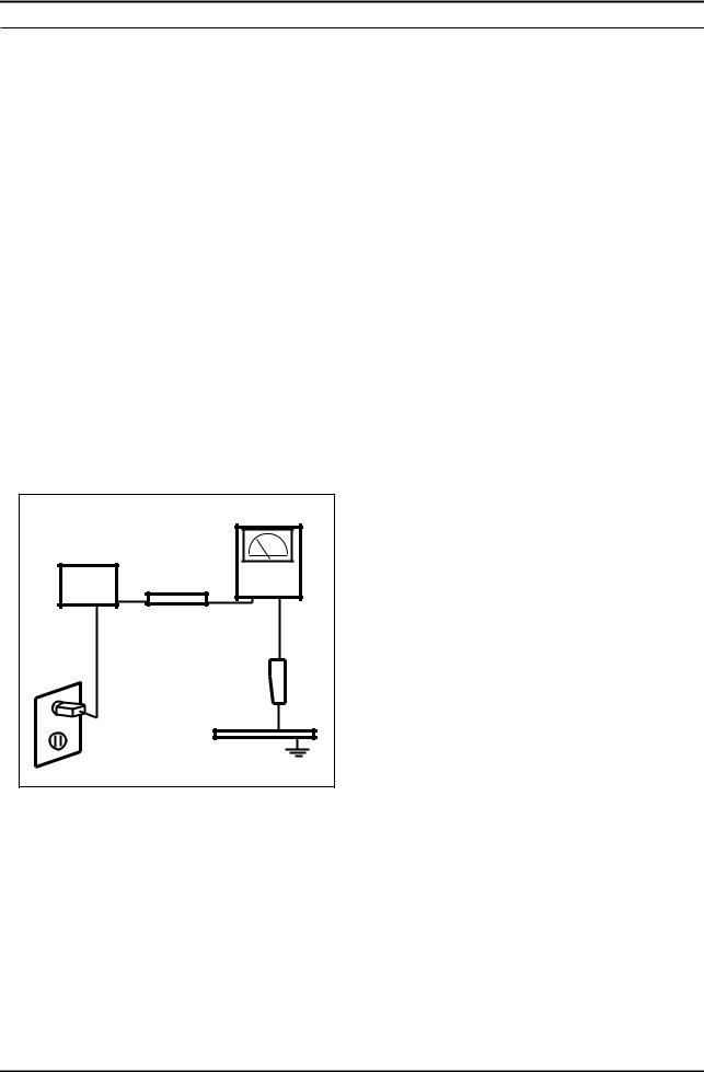
3.Leakage Current Hot Check (Figure 1-1):
WARNING : Do not use an isolation transformer during this test.
Use a leakage current tester or a metering system that complies with American National Standards Institute (ANSI C101.1, Leakage Current for Appliances), and Underwriters Laboratories (UL Publication UL1410, 59.7).
4.With the unit completely reassembled, plug the AC line cord directly into a 120V AC outlet. With the unit’s AC switch
(READING SHOULD)
NOT BE ABOVE 0.5mA
DEVICE |
LEAKAGE |
|
CURRENT |
|
|
UNDER |
|
|
TESTER |
|
|
TEST |
|
|
|
|
|
TEST ALL |
|
|
EXPOSED METAL |
|
|
SURFACES |
|
|
2-WIRE CORD |
|
|
*ALSO TEST WITH |
|
|
PLUG REVERSED |
|
|
(USING AC ADAPTER |
|
|
PLUG AS REQUIRED) |
EARTH |
|
|
|
|
|
GROUND |
Figure 1-1. Leakage Current Test Circuit |
|
|
first in the ON position and then OFF, measure the current between a known earth ground (metal water pipe, conduit, etc.) and all exposed metal parts, including: metal cabinets, screwheads and control shafts.
The current measured should not exceed 0.5 milliamp.
Reverse the power-plug prongs in the AC outlet and repeat the test.
1-1-4. Product Safety Notices
Some electrical and mechanical parts have special safety related characteristics which are often not evident from visual inspection. The protection they give may not be obtained by replacing them with components rated for higher voltage, wattage, etc. Parts that have special safety characteristics are identified by  on schematics and parts lists. A substitute replacement that does not have the same safety characteristics as the recommended replacement part might create shock, fire and/or other hazards. Product safety is under review continuously and new instructions are issued whenever appropriate.
1-1

1. Precautions
1-2. Servicing Precautions
WARNING: An electrolytic capacitor installed with the wrong polarity might explode.
Caution: Before servicing units covered by this service manual, read and follow the Safety Precautions section of this manual.
Note: If unforeseen circumstances create conflict between the following servicing precautions and any of the safety precautions, always follow the safety precautions.
1-2-1 General Servicing Precautions
1.Always unplug the unit’s AC power cord from the AC power source and disconnect the DC Power Jack before attempting to:
(a) remove or reinstall any component or assembly, (b) disconnect PCB plugs or connectors, (c) connect a test component in parallel with an electrolytic capacitor.
2.Some components are raised above the printed circuit board for safety. An insulation tube or tape is sometimes used. The internal wiring is sometimes clamped to prevent contact with thermally hot components. Reinstall all such elements to their original position.
3.After servicing, always check that the screws, components and wiring have been correctly reinstalled. Make sure that the area around the serviced part has not been damaged.
4.Check the insulation between the blades of the AC plug and accessible conductive parts (examples: metal panels, input terminals and earphone jacks).
5.Insulation Checking Procedure: Disconnect the power cord from the AC source and turn the power switch ON.
Connect an insulation resistance meter (500 V) to the blades of the AC plug. The insulation resistance between each blade of the AC plug and accessible conductive parts (see above) should be greater than 1 mega ohm.
6.Always connect a test instrument’s ground lead to the instrument chassis ground before connecting the positive lead; always remove the instrument’s ground lead last.
1-3. Electrostatically Sensitive Devices (ESD) Precautions
Some semiconductor (solid state) devices can be easily damaged by static electricity. Such components are commonly called Electrostatically Sensitive Devices (ESD). Examples of typical ESD are integrated circuits and some field-effect transistors. The following techniques will reduce the incidence of component damage caused by static electricity.
1.Immediately before handling any semiconductor components or assemblies, drain the electrostatic charge from your body by touching a known earth ground. Alternatively, wear a discharging wrist-strap device. To avoid a shock hazard, be sure to remove the wrist strap before applying power to the LCD TV.
2.After removing an ESD-equipped assembly, place it on a conductive surface such as aluminum foil to prevent accumulation of an electrostatic charge.
3.Do not use freon-propelled chemicals. These can generate electrical charges sufficient to damage ESDs.
4.Use only a grounded-tip soldering iron to solder or desolder ESDs.
5.Use only an anti-static solder removal device. Some solder removal devices not classified as “anti-static” can generate electrical charges sufficient to damage ESDs.
6.Do not remove a replacement ESD from its protective package until you are ready to install it. Most replacement ESDs are packaged with leads that are electrically shorted together by conductive foam, aluminum foil or other conductive materials.
7.Immediately before removing the protective material from the leads of a replacement ESD, touch the protective material to the chassis or circuit assembly into which the device will be installed.
Caution: Be sure no power is applied to the chassis or circuit and observe all other safety precautions.
8.Minimize body motions when handling unpackaged replacement ESDs. Motions such as brushing clothes together, or lifting your foot from a carpeted floor can generate enough static electricity to damage an ESD.
1-2

1. Precautions
1-4. Installation Precautions
1.For safety reasons, more than a people are required for carrying the product.
2.Keep the power cord away from any heat emitting devices, as a melted covering may cause fire or electric shock.
3.Do not place the product in areas with poor ventilation such as a bookshelf or closet. The increased internal temperature may cause fire.
4.Bend the external antenna cable when connecting it to the product. This is a measure to protect it from being exposed to moisture. Otherwise, it may cause a fire or electric shock.
5.Make sure to turn the power off and unplug the power cord from the outlet before repositioning the product. Also check the antenna cable or the external connectors if they are fully unplugged. Damage to the cord may cause fire or electric shock.
6.Keep the antenna far away from any high-voltage cables and install it firmly. Contact with the high-voltage cable or the antenna falling over may cause fire or electric shock.
7.When installing the product, leave enough space (4 in) between the product and the wall for ventilation purposes.
A rise in temperature within the product may cause fire.
1-3

1. Precautions
MEMO
1-4

2. Product specifications
2. Product specifications
2-1. Feature & Specifications
Model |
LE26C35*** |
|
|
Feature
DIGITAL-TV, RF, 1-HDMI, 1-COMPONENT, 1-A/V, D-SUB, 1-SCART
Brightness : 350cd/m2Contrast Ratio : 3000:1Response time : 8.5ms
|
|
Specifications |
|
|
|
|
|
Item |
|
Description |
|
|
|
|
|
LCD Panel |
TFT-LCD Panel, RGB Vertical stripe, Normaly balck |
||
|
|
|
|
Scanning Frequency |
Horizontal : 40 kHz ~ 80 kHz (Automatic) |
||
|
Vertical : 47 Hz ~ 63 Hz (Automatic) |
||
|
|
|
|
Display Colors |
16.7M color |
|
|
|
|
|
|
Maximum resolution |
Horizontal : 1366 Pixels |
||
|
Vertical : 768 Pixels |
||
|
|
|
|
Input Signal |
Analog 0.7 Vp-p ± 5% positive at 75Ω , internally terminated |
||
|
|
|
|
Input Sync Signal |
H/V Separate, TTL, P. or N. |
||
|
|
|
|
Maximum Pixel Clock rate |
86MHz |
|
|
|
|
|
|
Active Display |
|
|
|
Horizontal/Vertical |
22.7 x 12.7 inches (525.8(H) x 323.7(V) mm) |
||
|
|
|
|
AC power voltage & Frequency |
AC 110V ~ 240 @ 50/60 Hz |
||
|
|
|
|
Power Consumption |
Under 80W (Under 1W , Stand by) |
||
|
|
|
|
Dimensions |
26.5 x 8.75 x 20.21 inches (673.3 x 222.2 x 513.4 mm) with stand |
||
Set (W x D x H) |
|||
26.5 x 3.31 x 17.95 inches (673.3 x 84.0 x 456.0 mm) without stand |
|||
|
|
|
|
Weight (Set) |
13.45 lbs (6.1 Kg)_with stand |
||
|
12.57 lbs (5.7 Kg)_without stand |
||
|
|
|
|
TV System |
Tuning |
Frequency Synthesize (Refer to detailed Frequency Table) |
|
|
|
|
|
|
System |
PAL/SECAM, DVB-T |
|
|
|
|
|
|
Sound |
MONO, STEREO, NICAM, MPEG, DD, DD+, HE-AAC |
|
|
|
|
|
Environmental Considerations |
Operating Temperature : 50˚F ~ 104˚F (10˚C ~ 40˚C) |
||
|
Operating Humidity : 10% ~ 80%, non-condensing |
||
|
Storage temperature : -13˚F ~ 113˚F (-25˚C ~ 45˚C) |
||
|
Storage Humidity : 5% ~ 95%, non-condensing |
||
|
|
||
Audio Spec. |
- MAX Internal Audio Output Power : Each 5W(Left/Right) |
||
|
- BASS Control Range : -8 dB ~ + 8dB |
||
|
- TREBLE Control Range : -8 dB ~ +8 dB |
||
|
- Headphone Out : 10 mW MAX |
||
|
- Output Frequency : RF : 80 Hz ~ 15 kHz |
||
|
|
A/V : 80 Hz ~ 20 kHz |
|
Note: Media play, Game Mode, Energy Saving
2-1

2. Product specifications
Model |
LE32C35*** |
|
|
Feature
DIGITAL-TV, RF, 1-HDMI, 1-COMPONENT, 1-A/V, D-SUB, 1-SCART
Brightness : 350cd/m2Contrast Ratio : 3,000:1Response time : 8.5ms
|
|
Specifications |
|
|
|
|
|
Item |
|
Description |
|
|
|
|
|
LCD Panel |
TFT-LCD Panel, RGB Vertical stripe, Normaly balck |
||
|
|
|
|
Scanning Frequency |
Horizontal : 44 kHz ~ 53 kHz (Automatic) |
||
|
Vertical : 50 Hz ~ 60 Hz (Automatic) |
||
|
|
|
|
Display Colors |
16.7M color |
|
|
|
|
|
|
Maximum resolution |
Horizontal : 1366 Pixels |
||
|
Vertical : 768 Pixels |
||
|
|
|
|
Input Signal |
Analog 0.7 Vp-p ± 5% positive at 75Ω , internally terminated |
||
|
|
|
|
Input Sync Signal |
H/V Separate, TTL, P. or N. |
||
|
|
|
|
Maximum Pixel Clock rate |
86MHz |
|
|
|
|
|
|
Active Display |
|
|
|
Horizontal/Vertical |
27.47 x 11.50 inches (697.68(H) x 392.26(V) mm) |
||
|
|
|
|
AC power voltage & Frequency |
AC 110V ~ 240 @ 50/60 Hz |
||
|
|
|
|
Power Consumption |
Under 95W (Under 1W , Stand by) |
||
|
|
|
|
Dimensions |
31.31 x 9.73 x 23.04 inches (795.3 x 247.2 x 585.3 mm)_with stand |
||
Set (W x D x H) |
|||
31.31 x 3.3 x 20.70 inches (795.3 x 84.0 x 525.8 mm)_without stand |
|||
|
|
|
|
Weight (Set) |
16.76 lbs (7.6 Kg)_with stand |
||
|
15.65 lbs (7.1 Kg)_without stand |
||
|
|
|
|
TV System |
Tuning |
Frequency Synthesize (Refer to detailed Frequency Table) |
|
|
|
|
|
|
System |
PAL/SECAM, DVB-T |
|
|
|
|
|
|
Sound |
MONO, STEREO, NICAM, MPEG, DD, DD+, HE-AAC |
|
|
|
|
|
Environmental Considerations |
Operating Temperature : 50˚F ~ 104˚F (10˚C ~ 40˚C) |
||
|
Operating Humidity : 10% ~ 80%, non-condensing |
||
|
Storage temperature : -13˚F ~ 113˚F (-25˚C ~ 45˚C) |
||
|
Storage Humidity : 5% ~ 95%, non-condensing |
||
|
|
||
Audio Spec. |
- MAX Internal Audio Output Power : Each 5W(Left/Right) |
||
|
- BASS Control Range : -8 dB ~ + 8dB |
||
|
- TREBLE Control Range : -8 dB ~ +8 dB |
||
|
- Headphone Out : 10 mW MAX |
||
|
- Output Frequency : RF : 80 Hz ~ 15 kHz |
||
|
|
A/V : 80 Hz ~ 20 kHz |
|
Note: Media play, Game Mode, Energy Saving
2-2

2. Product specifications
2-2. Specification Comparison to Old Models
O : application, X : non-application
Model |
LC3D(LE26/32C35***) |
LB3F(LE**B35***) |
Design
Display Type |
LCD TV |
|
LCD TV |
|
|
|
|
|
|
Built-in Tuner |
O |
|
O |
|
|
|
|
|
|
Resolution |
1360 x 768 |
|
1360 x 768 |
|
|
|
|
|
|
LCD Panel |
TFT LCD Panel 50Hz |
|
TFT LCD Panel 50Hz |
|
|
|
|
|
|
Screen Size |
26"/32" |
|
26"/32" |
|
|
|
|
|
|
Picture ratio |
16 : 9 |
|
16 : 9 |
|
|
|
|
|
|
26 |
26.5 x 8.75 x 20.21 inches_with stand |
26 |
26.2 x 8.5 x 19.5 inches_with stand |
|
Dimensions (W x H x D) |
|
|
|
|
32 |
31.31 x 9.73 x 23.04 inches_with stand |
32 |
31.4 x 8.6 x 22.6 inches_with stand |
|
|
|
|
|
|
26 |
9.92 lbs_with stand |
26 |
15.78 lbs_with stand |
|
Weight |
|
|
|
|
32 |
11.99 lbs_with stand |
32 |
22.13 lbs_with stand |
|
|
|
|
|
|
Brightness |
|
300 cd/m2 |
|
250 ~ 450 cd/m2 |
Contrast Ratio |
3,000:1 |
|
800 ~ 5,000:1 |
|
|
|
|
|
|
Picture Enhacer |
DNIe(SETD-10) |
|
DNIe (Saturn4) |
|
|
|
|
|
|
Equalizer |
O |
|
O |
|
|
|
|
|
|
Auto Volume Control |
O |
|
O |
|
|
|
|
|
|
Surround Sound |
Virtural Surround |
|
SRS TruSurround HD |
|
|
|
|
|
|
Speaker Output |
|
5W |
|
5W |
Energy Saving |
O |
|
O |
|
|
|
|
|
|
Antenna |
1(Air/CABLE) |
|
1(Air) |
|
2-3

2. Product specifications
2-3. Detail Factory Option
If you replace the main board with new one, please change the factory option as well. The options you must change are “Type”.
|
|
Model Name |
LE26C35*** |
LE32C35*** |
|
|
|
|
|
|
|
|
|
Vendor |
CHILIN |
CHILIN |
|
|
Panel |
|
|
|
|
|
CODE |
BN07-00866A |
BN07-00867A |
||
|
|
|
|
|
|
|
|
SPEC |
T260HA01-DB |
T315HA01-DB |
|
|
|
|
|
|
|
|
SMPS |
Vendor |
HANSOE |
HANSOE |
|
|
|
|
|
|
|
|
|
CODE |
BN44-00368B |
BN44-00369B |
|
|
|
|
|
|
|
Byte |
Item |
SPEC |
I26HD_AHS |
I32HD_AHS |
|
|
|
Adjustment Range |
|
|
|
|
|
|
|
|
|
1 |
Factory Reset |
- |
|
|
|
|
|
|
|
|
|
|
|
19D6THOC/19I6THOC/22D6THOC/ |
|
|
|
|
|
22L6THOC/22I6THOC/26D6THOC/ |
|
|
|
|
|
26L6AHOC/32A6AHOC/32L6AHOC/ |
|
|
|
|
|
32D6AHOC/37L6AHOC/37I6AHOC/ |
|
|
|
2 |
Type |
40L6AHOC/32A6AFOC/32L6AFOC/ |
26P6AHOC |
32P6AHOC |
|
|
|
32D6AFOC/37L6AFOC/37D6AFOC/ |
|
|
|
|
|
40A6AFOC/40L6AFOC/40D6AFOC/ |
|
|
|
|
|
46A6AFOC/46L6AFOC/46D6AFOC/ |
|
|
|
|
|
52A6AFOC/52L6AFOC/ |
|
|
|
|
|
|
|
|
|
3 |
Local set |
EU/EU_ITALY/EU_AFRICA/EU_LSRAEL |
EU |
EU |
|
/NORDIG/AD_Au/CIS |
|||||
|
|
|
|
||
|
|
|
|
|
|
4 |
Model |
LC350/LC450/LC530/LC550/LC650 |
LC350 |
LC350 |
|
|
|
|
|
|
|
5 |
TUNER |
DRXKXEMCO/S2SEMCO/T2CXD/DRXKSEM_E |
DRXKXEMCO |
DRXKXEMCO |
|
DRXKAALPS/DRXKSEM_2 |
|||||
|
|
|
|
||
|
|
|
|
|
|
6 |
DDR |
0/1/2 |
0 |
0 |
|
|
|
|
|
|
|
7 |
Light Effect |
On/Off |
Off |
Off |
|
|
|
|
|
|
|
8 |
Ch Table |
SUWON/SESK/SHE/TTSEC/SDMA/ |
|
|
|
SERK/SEIN/SAVINA/SIEL/TSE/s |
|
|
|||
|
|
|
|
||
|
|
|
|
|
|
9 |
Country |
- |
- |
- |
|
|
|
|
|
|
|
10 |
PDP GROUP |
P43A_42Sn |
**** |
**** |
|
|
|
|
|
|
|
11 |
Front Color |
|
|
|
|
|
|
|
|
|
2-4
Loading...