


LE19C350D1WXBT
Table of contents
 Loading...
LCD-TV
Chassis : N82C
Model : LE19C35***
SERVICE
LE22C35***
Manual
TFT-LCD TV Contents
1. Precautions
2. Product specications
3. Disassembly and Reassembly
4. Troubleshooting
5. Exploded View & Part List
6. Wiring Diagram
LE19C35*** / LE22C35***
Refer to the service manual in the GSPN (see the rear cover) for the more information.

Contents
1. Precautions .............................................................................................................. 1-1
1-1. Safety Precautions ......................................................................................................... 1-1
1-2. Servicing Precautions .....................................................................................................1-2
1-3. Electrostatically Sensitive Devices (ESD) Precautions .................................................. 1-2
1-4. Installation Precautions .................................................................................................. 1-3
2. Product specications ............................................................................................ 2-1
2-1. Feature & Specications ................................................................................................. 2-1
2-2. Specication Comparison to Old Models ........................................................................ 2-3
2-3. Detail Factory Option ...................................................................................................... 2-4
2-4. Accessories .................................................................................................................... 2-8
3. Disassembly and Reassembly ............................................................................... 3-1
3-1. Disassembly and Reassembly ....................................................................................... 3-1
4. Troubleshooting ...................................................................................................... 4-1
4-1. Troubleshooting .............................................................................................................. 4-1
4-2. Alignments and Adjustments ........................................................................................ 4-25
4-3. Factory Mode Adjustments ........................................................................................... 4-26
4-4. White Balance - Calibration .......................................................................................... 4-34
4-5. White Ratio (Balance) Adjustment ................................................................................ 4-34
4-6. Servicing Information .................................................................................................... 4-35
4-7. How To Upgrade Sub Micom With Ddc Manager ......................................................... 4-36
4-8. Mechanical diagram ..................................................................................................... 4-38
4-9. PCB diagram ................................................................................................................ 4-39
5. Exploded View & Part List ...................................................................................... 5-1
5-1. Exploded View ................................................................................................................ 5-1
5-2. Parts List ......................................................................................................................... 5-3
6. Wiring Diagram ........................................................................................................ 6-1
6-1. Wiring Diagram ............................................................................................................... 6-1
6-2. Connector ....................................................................................................................... 6-3
6-3. Connector Functions ...................................................................................................... 6-4
6-4. Cables ............................................................................................................................ 6-4
GSPN (Global Service Partner Network)
Area Web Site
North America http://service.samsungportal.com
Latin America http://latin.samsungportal.com
CIS http://cis.samsungportal.com
Europe http://europe.samsungportal.com
China http://china.samsungportal.com
Asia http://asia.samsungportal.com
Mideast & Africa http://mea.samsungportal.com
This Service Manual is a property of Samsung Electronics Co.,Ltd.
Any unauthorized use of Manual can be punished under applicable
International and/or domestic law.
© 2010 Samsung Electronics Co.,Ltd.
All rights reserved.
Printed in Korea
P/N: BN82-00930A-00
1. Precautions
1. Precautions
1-1. Safety Precautions
Follow these safety, servicing, and ESD precautions to prevent damage and to protect against potential hazards such as
electrical shock.
1-1-1. Warnings
For continued safety, do not attempt to modify any circuitry.1.
1-1-2. Servicing the LCD TV
When servicing the LCD TV, Disconnect the AC line cord from the AC outlet.1.
It is essential that service technicians have an accurate voltage meter available at all times. 2.
Check the calibration of this meter periodically.
1-1-3. Fire and Shock Hazard
Before returning the LCD TV to the user, perform the following safety checks:
Inspect each lead dress to make certain that the leads are not pinched or that hardware is not lodged between the 1.
chassis and other metal parts in the LCD TV.
Inspect all protective devices such as nonmetallic control knobs, insulating materials, cabinet backs, adjustment and 2.
compartment covers or shields, isolation resistor capacitor networks, mechanical insulators, etc.
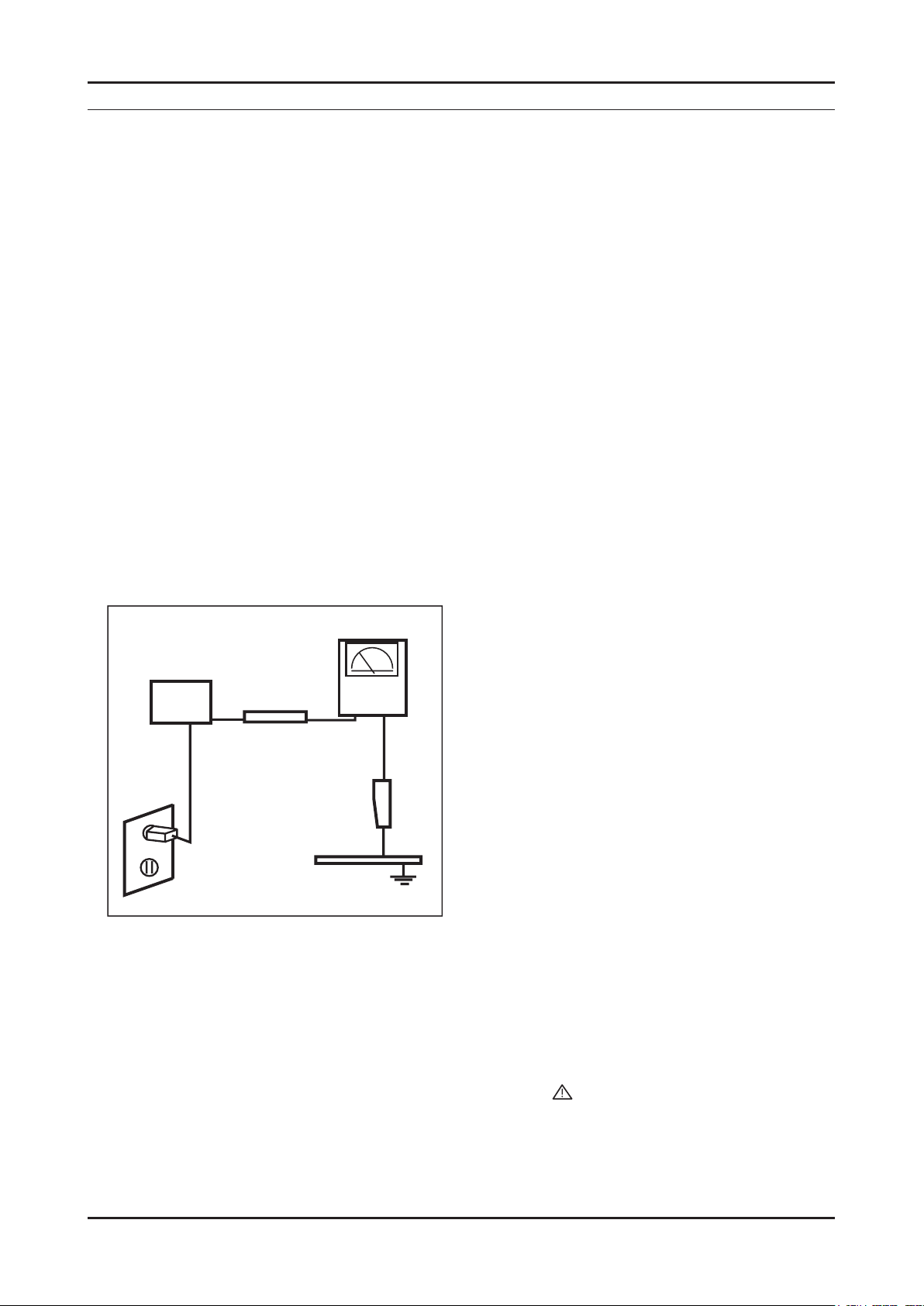
Leakage Current Hot Check (Figure 1-1): 3.
WARNING : Do not use an isolation transformer during this test.
Use a leakage current tester or a metering system that complies with American National Standards Institute (ANSI
C101.1, Leakage Current for Appliances), and Underwriters Laboratories (UL Publication UL1410, 59.7).
With the unit completely reassembled, plug the AC line cord directly into a 120V AC outlet. With the unit’s AC switch 4.
(READING SHOULD)
NOT BE ABOVE 0.5mA
DEVICE
UNDER
TEST
2-WIRE CORD
*ALSO TEST WITH
PLUG REVERSED
(USING AC ADAPTER
PLUG AS REQUIRED)
TEST ALL
EXPOSED METAL
SURFACES
LEAKAGE
CURRENT
TESTER
EARTH
GROUND
Figure 1-1. Leakage Current Test Circuit
rst in the ON position and then OFF, measure the current between a known earth ground (metal water pipe, conduit,
etc.) and all exposed metal parts, including: metal cabinets, screwheads and control shafts.
The current measured should not exceed 0.5 milliamp.
Reverse the power-plug prongs in the AC outlet and repeat the test.
1-1-4. Product Safety Notices
Some electrical and mechanical parts have special safety related characteristics which are often not evident from visual
inspection. The protection they give may not be obtained by replacing them with components rated for higher voltage,
wattage, etc. Parts that have special safety characteristics are identied by on schematics and parts lists. A substitute
replacement that does not have the same safety characteristics as the recommended replacement part might create
shock, re and/or other hazards. Product safety is under review continuously and new instructions are issued whenever
appropriate.
1-1

1-2
1. Precautions
1-2. Servicing Precautions
WARNING: An electrolytic capacitor installed with the wrong polarity might explode.
Caution: Before servicing units covered by this service manual, read and follow the Safety Precautions section of
this manual.
Note: If unforeseen circumstances create conict between the following servicing precautions and any of the
safety precautions, always follow the safety precautions.
1-2-1 General Servicing Precautions
Always unplug the unit’s AC power cord from the AC power source and disconnect the DC Power Jack before 1.
attempting to:
(a) remove or reinstall any component or assembly, (b) disconnect PCB plugs or connectors, (c) connect a test
component in parallel with an electrolytic capacitor.
Some components are raised above the printed circuit board for safety. An insulation tube or tape is sometimes 2.
used. The internal wiring is sometimes clamped to prevent contact with thermally hot components. Reinstall all such
elements to their original position.
After servicing, always check that the screws, components and wiring have been correctly reinstalled. Make sure that 3.
the area around the serviced part has not been damaged.
Check the insulation between the blades of the AC plug and accessible conductive parts (examples: metal panels, 4.
input terminals and earphone jacks).
Insulation Checking Procedure: Disconnect the power cord from the AC source and turn the power switch ON. 5.
Connect an insulation resistance meter (500 V) to the blades of the AC plug. The insulation resistance between each
blade of the AC plug and accessible conductive parts (see above) should be greater than 1 mega ohm.
Always connect a test instrument’s ground lead to the instrument chassis ground before connecting the positive lead; 6.
always remove the instrument’s ground lead last.
1-3. Electrostatically Sensitive Devices (ESD) Precautions
Some semiconductor (solid state) devices can be easily damaged by static electricity. Such components are commonly
called Electrostatically Sensitive Devices (ESD). Examples of typical ESD are integrated circuits and some eld-effect
transistors. The following techniques will reduce the incidence of component damage caused by static electricity.
Immediately before handling any semiconductor components or assemblies, drain the electrostatic charge from your 1.
body by touching a known earth ground. Alternatively, wear a discharging wrist-strap device. To avoid a shock hazard,
be sure to remove the wrist strap before applying power to the LCD TV.
After removing an ESD-equipped assembly, place it on a conductive surface such as aluminum foil to prevent 2.
accumulation of an electrostatic charge.
Do not use freon-propelled chemicals. These can generate electrical charges sufcient to damage ESDs.3.
Use only a grounded-tip soldering iron to solder or desolder ESDs.4.
Use only an anti-static solder removal device. Some solder removal devices not classied as “anti-static” can generate 5.
electrical charges sufcient to damage ESDs.
Do not remove a replacement ESD from its protective package until you are ready to install it. Most replacement ESDs 6.
are packaged with leads that are electrically shorted together by conductive foam, aluminum foil or other conductive
materials.
Immediately before removing the protective material from the leads of a replacement ESD, touch the protective 7.
material to the chassis or circuit assembly into which the device will be installed.
Caution: Be sure no power is applied to the chassis or circuit and observe all other safety precautions.
Minimize body motions when handling unpackaged replacement ESDs. Motions such as brushing clothes together, 8.
or lifting your foot from a carpeted oor can generate enough static electricity to damage an ESD.

1-3
1. Precautions
1-4. Installation Precautions
For safety reasons, more than a people are required for carrying the product.1.
Keep the power cord away from any heat emitting devices, as a melted covering may cause re or electric shock.2.
Do not place the product in areas with poor ventilation such as a bookshelf or closet. The increased internal 3.
temperature may cause re.
Bend the external antenna cable when connecting it to the product. This is a measure to protect it from being exposed 4.
to moisture. Otherwise, it may cause a re or electric shock.
Make sure to turn the power off and unplug the power cord from the outlet before repositioning the product. Also check 5.
the antenna cable or the external connectors if they are fully unplugged. Damage to the cord may cause re or electric
shock.
Keep the antenna far away from any high-voltage cables and install it rmly. Contact with the high-voltage cable or the 6.
antenna falling over may cause re or electric shock.
When installing the product, leave enough space (4 in) between the product and the wall for ventilation purposes. 7.
A rise in temperature within the product may cause re.

1. Precautions
MEMO
1-4
2. Product specications
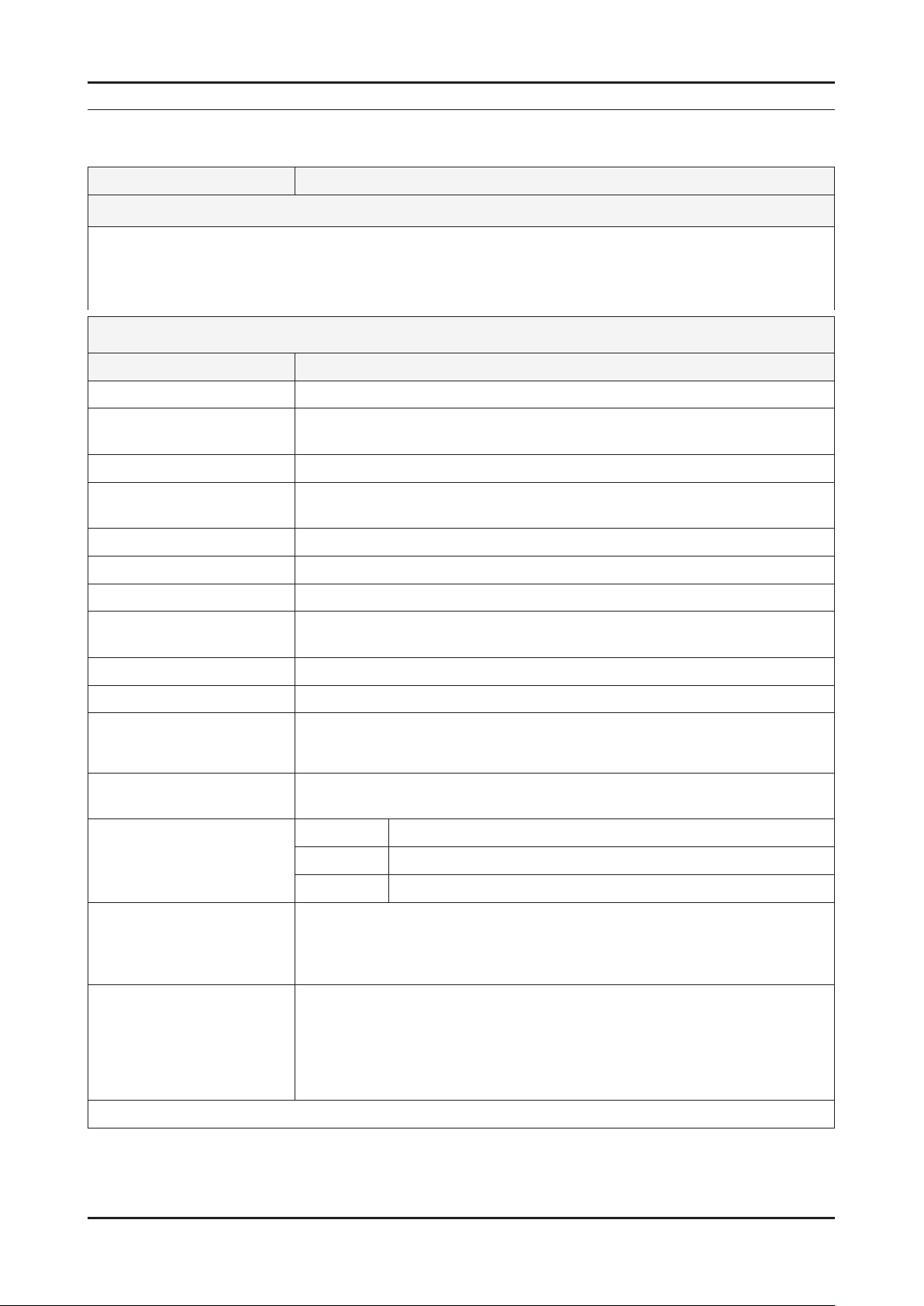
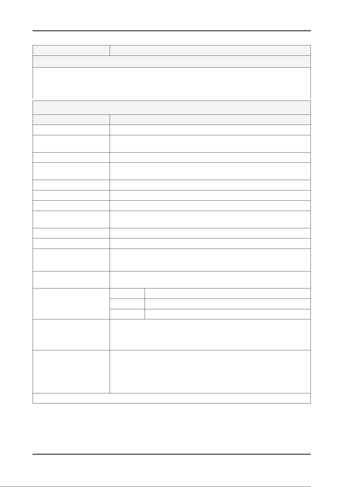
2-1. Feature & Specications
Model LE19C35***
2. Product specications
Feature
DIGITAL-TV, RF, 1-HDMI, 1-COMPONENT, 1-A/V, D-SUB, 1-SCART ሪ
Brightness : 250cd/m ሪ
Contrast Ratio : 1,000:1 ሪ
Response time : 5ms ሪ
Item Description
LCD Panel TFT-LCD Panel, RGB Vertical Stripe, Normally white, TN
Scanning Frequency Horizontal : 34KHz ~ 70KHz (Automatic)
Display Colors 16.7M color
Maximum resolution Horizontal : 1366 Pixels
Input Signal Analog 0.7 Vp-p ± 5% positive at 75Ω , internally terminated
Input Sync Signal H/V Separate, TTL, P. or N.
Maximum Pixel Clock rate 95.6MHz
Active Display
Horizontal/Vertical 16.13 x 9.07 inches (409.8(H) x 230.4 (V) mm)
AC power voltage & Frequency AC 110V ~ 240 @ 50/60 Hz
2
Specications
Vertical : 50Hz ~ 76Hz (Automatic)
Vertical : 768 Pixels
Power Consumption Under 35W (Under 1W , Stand by)
Dimensions
Set (W x D x H)
Weight (Set) 9.03 lbs (4.1 Kg)_with stand
TV System Tuning Frequency Synthesize (Refer to detailed Frequency Table)
Environmental Considerations Operating Temperature : 50˚F ~ 104˚F (10˚C ~ 40˚C)
Audio Spec. - MAX Internal Audio Output Power : Each 3W(Left/Right)
Note: DNSe, Game Mode, Energy Saving
18.16 x 7.09 x 13.7 inches (461.3 x 180.2 x 348.0 mm)_with stand
18.16 x 2.54 x 12.69 inches (461.2 x 64.4 x 322.2 mm)_without stand
8.59 lbs (3.9 Kg)_without stand
System PAL/SECAM, DVB-T
Sound MONO, STEREO, NICAM, MPEG, DD, DD+, HE-AAC
Operating Humidity : 10% ~ 80%, non-condensing
Storage temperature : -13˚F ~ 113˚F (-25˚C ~ 45˚C)
Storage Humidity : 5% ~ 95%, non-condensing
- BASS Control Range : -8 dB ~ + 8dB
- TREBLE Control Range : -8 dB ~ +8 dB
- Headphone Out : 10 mW MAX
- Output Frequency : RF : 80 Hz ~ 15 kHz
A/V : 80 Hz ~ 20 kHz
2-1
2-2
2. Product specications
Model LE22B35***
Feature
DIGITAL-TV, RF, 1-HDMI, 1-COMPONENT, 1-A/V, D-SUB, 1-SCART ሪ
Brightness : 300cd/m ሪ
2
Contrast Ratio : 800:1 ሪ
Response time : 5ms ሪ
Specications
Item Description
LCD Panel TFT-LCD Panel, RGB Vertical Stripe, Normally white, TN
Scanning Frequency Horizontal : 30 KHz ~ 60 KHz (Automatic)
Vertical : 57 Hz ~ 63 Hz (Automatic)
Display Colors 16.7M color
Maximum resolution Horizontal : 1366 Pixels
Vertical : 768 Pixels
Input Signal Analog 0.7 Vp-p ± 5% positive at 75Ω , internally terminated
Input Sync Signal H/V Separate, TTL, P. or N.
Maximum Pixel Clock rate 82MHz
Active Display
Horizontal/Vertical 18.80 x 10.57 inches (477.42(H) x 268.42(V) mm)
AC power voltage & Frequency AC 110V ~ 240 @ 50/60 Hz
Power Consumption Under 55W (Under 1W , Stand by)
Dimensions
Set (W x D x H)
21.07 x 6.76 x 16.57 inches (535.3 x 171.8 x 420.9 mm)_with stand
21.07 x 3.37 x 14.40 inches (535.3 x 85.5 x 365.8 mm)_without stand
Weight (Set) 9.25 lbs (4.2 Kg)_with stand
8.58 lbs (3.9 Kg)_without stand
TV System Tuning Frequency Synthesize (Refer to detailed Frequency Table)
System PAL/SECAM, DVB-T
Sound MONO, STEREO, NICAM, MPEG, DD, DD+, HE-AAC
Environmental Considerations Operating Temperature : 50˚F ~ 104˚F (10˚C ~ 40˚C)
Operating Humidity : 10% ~ 80%, non-condensing
Storage temperature : -13˚F ~ 113˚F (-25˚C ~ 45˚C)
Storage Humidity : 5% ~ 95%, non-condensing
Audio Spec. - MAX Internal Audio Output Power : Each 3W(Left/Right)
- BASS Control Range : -8 dB ~ + 8dB
- TREBLE Control Range : -8 dB ~ +8 dB
- Headphone Out : 10 mW MAX
- Output Frequency : RF : 80 Hz ~ 15 kHz
A/V : 80 Hz ~ 20 kHz
Note: DNSe, Game Mode, Energy Saving
2-3
2. Product specications
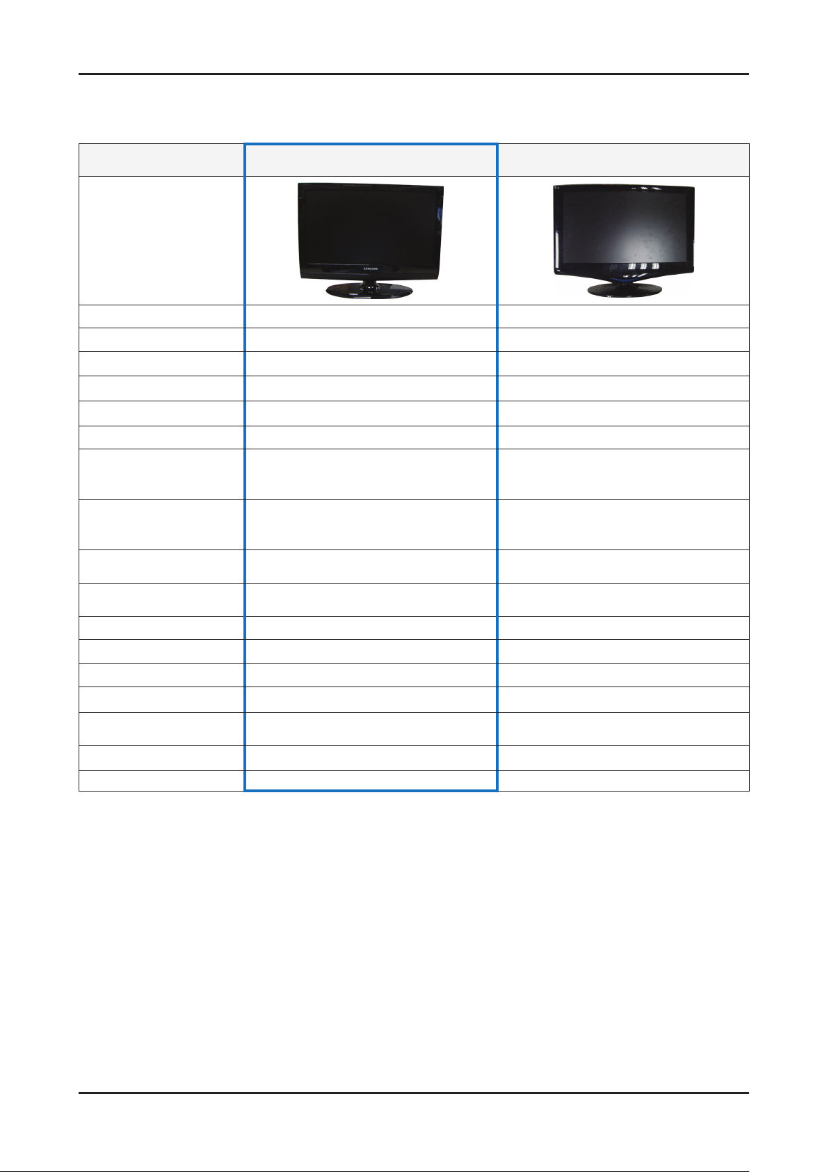
2-2. Specication Comparison to Old Models
O : application, X : non-application ※
Model LC3D (LE19/22C35***) LC3D(LE19/22C35***)
Design
Display Type LCD TV LCD TV
Built-in Tuner O O
Resolution 1360 x 768 1366 x 768
LCD Panel TFT LCD Panel 50Hz TFT LCD Panel 50Hz
Screen Size 19" / 22" 22"
Picture ratio 16 : 9 16 : 9
Dimensions (W x H x D)
Weight
Brightness
Contrast Ratio
Picture Enhacer DNIe(SETD-10) DNIe (Saturn4)
Equalizer O O
Auto Volume Control O O
Surround Sound Virtural Surround SRS TruSurround XT
Speaker Output 3W + 3W 3W + 3W
Energy Saving O O
Antenna 1(Cable/Air) 1(Cable/Air)
19 18.16 x 6.34 x 14.33 inches_with stand
22 21.07 x 6.76 x 16.57 inches_with stand
19 9.03 lbs_with stand
22 9.25 lbs_with stand
19" : 250 cd/m
22" : 300 cd/m
19" : 1,000:1
22" : 800:1
2
2
22 21.95 x 16.73 x 7.98 inches_with stand
22 8.82 lbs_with stand
300 cd/m
2
800 : 1
2-4
2. Product specications
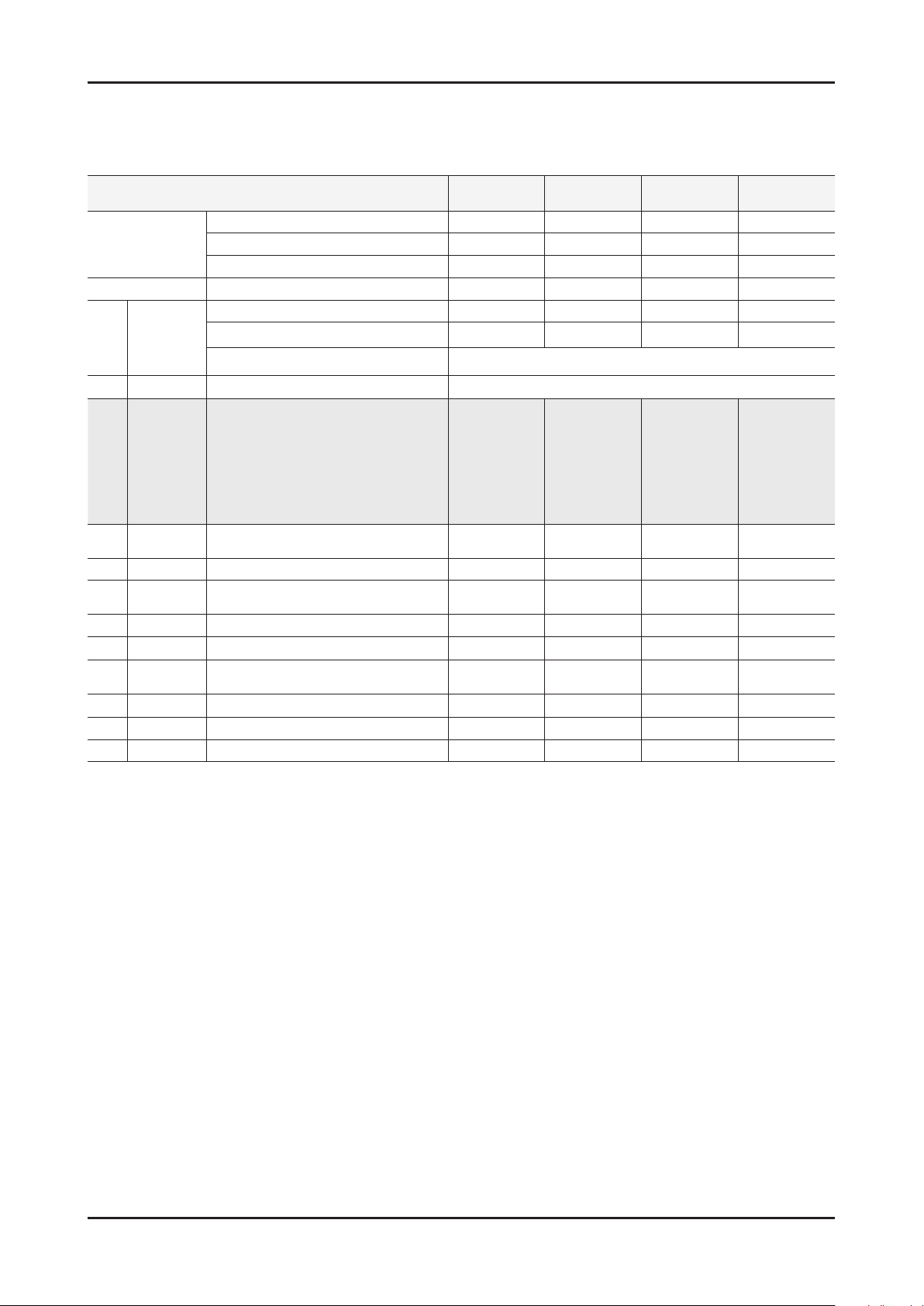
2-3. Detail Factory Option
If you replace the main board with new one, please change the factory option as well. ※
The options you must change are “Type”.
Model Name LE19C35*** LE19C35*** LE19C35*** LE22C35***
Vendor INNOL CPT AML CHILIN
Panel
SMPS Vendor FSP FSP SEMCO AMBIT
Byte Item
1 Factory Reset -
19D6THOC/19I6THOC/22D6THOC/
22L6THOC/22I6THOC/26D6THOC/
26L6AHOC/32A6AHOC/32L6AHOC/
2 Type
3 Local set
4 Model LC350/LC450/LC530/LC550/LC650 LC350 LC350 LC350 LC350
5 TUNER
6 DDR 0/1/2 0 0 0 0
7 Light Effect On/Off Off Off Off Off
8 Ch Table
9 Country - - - - -
10 PDP GROUP P43A_42Sn **** **** **** ****
11 Front Color
32D6AHOC/37L6AHOC/37I6AHOC/
40L6AHOC/32A6AFOC/32L6AFOC/
32D6AFOC/37L6AFOC/37D6AFOC/
40A6AFOC/40L6AFOC/40D6AFOC/
46A6AFOC/46L6AFOC/46D6AFOC/
EU/EU_ITALY/EU_AFRICA/EU_LSRAEL
DRXKXEMCO/S2SEMCO/T2CXD/DRXKSEM_E
DRXKAALPS/DRXKSEM_2
SUWON/SESK/SHE/TTSEC/SDMA/
SERK/SEIN/SAVINA/SIEL/TSE/s
CODE BN07-00766A BN07-00623A BN07-00703A BN07-00744A
SPEC MT185GW01 V2 CLAA185WA03 LTM185AT01-V T216HA01-DB
CODE BN44-00328B BN44-00328B BN44-00328A BN44-00366B
SPEC FSP035-2PI10 FSP035-2PI10 PSIV350310A K02P140.00
Adjustment Range
1906THOC 19I6THOC 19A6TH0C 22P6THOC
52A6AFOC/52L6AFOC/
/NORDIG/AD_Au/CIS
EU EU EU EU
DRXKXEMCO DRXKXEMCO DRXKXEMCO DRXKXEMCO
2-5
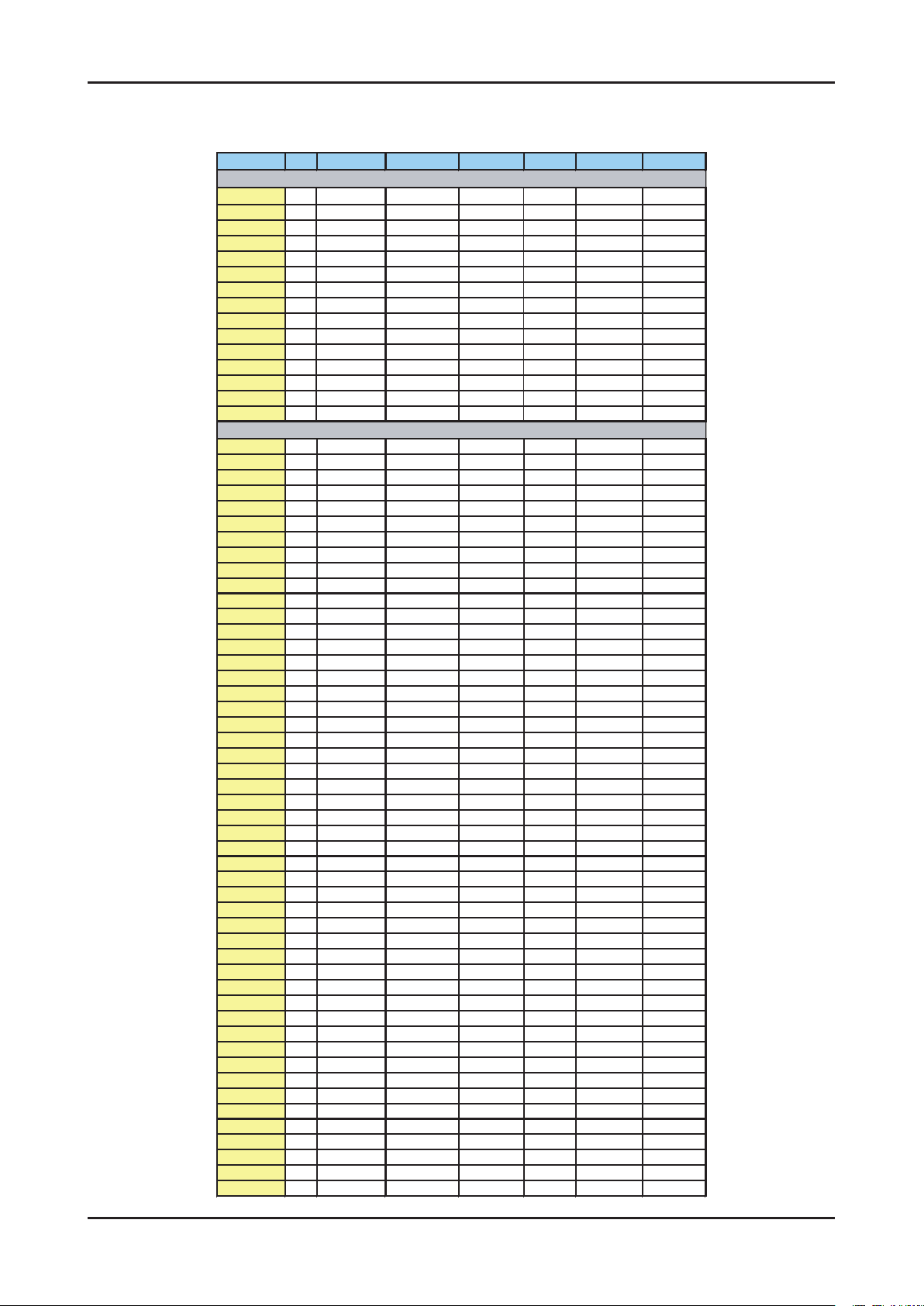
2. Product specications
Frequency (DTV)
Channel UK France Germany Italy Spain Sweden Finland
VHF
[A] 56
[B] 64.5
[C] 84.5
[D] 177.5
[5] 178.75 [5] 177.5 [E] 186 [5] 177.5 [5] 177.5
[6] 186.75 [6] 184.5 [F] 194.5 [6] 184.5 [6] 184.5
[7] 194.75 [7] 191.5 [G] 203.5 [7] 191.5 [7] 191.5
[8] 202.75 [8] 198.5 [H] 212.5 [8] 198.5 [8] 198.5
[9] 210.75 [9] 205.5 [H1] 219.5 [9] 205.5 [9] 205.5
[10] 218.75
[10] 212.5 [H2] 226.5 [10] 212.5
[10] 212.5
[11] 219.5 [11] 219.5
[11] 219.5
[12] 226.5 [12] 226.5
[12] 226.5
UHF
21 474 474 474 474 474 474 474
22 482 482 482 482 482 482 482
23 490 490 490 490 490 490 490
24 498 498 498 498 498 498 498
25 506 506 506 506 506 506 506
26 514 514 514 514 514 514 514
27 522 522 522 522 522 522 522
28 530 530 530 530 530 530 530
29 538 538 538 538 538 538 538
30 546 546 546 546 546 546 546
31 554 554 554 554 554 554 554
32 562 562 562 562 562 562 562
33 570 570 570 570 570 570 570
34 578 578 578 578 578 578 578
35 586 586 586 586 586 586 586
36 594 594 594 594 594 594 594
37 602 602 602 602 602 602 602
38 610 6
10 610 610 610 610 610
39 618 618 618 618 618 618 618
40 626 626 626 626 626 626 626
41 634 634 634 634 634 634 634
42 642 642 642 642 642 642 642
43 650 650 650 650 650 650 650
44 658 658 658 658 658 658 658
45 666 666 666 666 666 666 666
46 674 674 674 674 674 674 674
47 682 682 682 682 682 682 682
48 690 690 690 690 690 690 690
49 698 698 698 698 698 698 698
50 706 706 706 706 706 706 706
51 714 714 714 714 714 714 714
52 722 722 722 722 722 722 722
53 730 730 730 730 730 730 730
54 738 738 738 738 738 738 738
55 746 746 746 746 7
46 746 746
56 754 754 754 754 754 754 754
57 762 762 762 762 762 762 762
58 770 770 770 770 770 770 770
59 778 778 778 778 778 778 778
60 786 786 786 786 786 786 786
61 794 794 794 794 794 794 794
62 802 802 802 802 802 802 802
63 810 810 810 810 810 810 810
64 818 818 818 818 818 818 818
65 826 826 826 826 826 826 826
66 834 834 834 834 834 834 834
67 842 842 842 842 842 842 842
68 850 850 850 850 850 850 850
69 858 858 858 858 858 858
2-6
2. Product specications
Australia Netherlands China Hongkong Taiwan
[0] 48.5 [1]52. 5
[1] 59.5
[2]60.5
[2] 66.5
[3]68.5
[3] 88.5
[4]80
[4] 97.5 [5] 174.5
[5]88
[5] 104.5 [6] 181.5
[6]171
[5A] 140.5 [7] 188.5
[7]179
[6] 177.5 [8] 195.5
[8]187
[7] 184.5 [9] 202.5
[9]195
[8] 191.5 [10] 209.5
[10]203
[9] 198.5 [11] 216.5
[11]211
[9A] 205.5 [12] 223.5
[12]219
[10] 212.5
[11] 219.5
[12] 226.5
474 [13]474 [21]474 [14]473
482 [14]482 [22]482 [15]479
490 [15]490 [23]490 [16]485
498 [16]498 [24]498 [17]491
506 [17]506 [25]506 [18]497
514 [18]514 [26]514 [19]503
520~526, 6MHz
522 [19]522 [27]522 [20]509
529.5 530 [20]530 [28]530 [21]515
536.5 538 [21]538 [29]538 [22]521
543.5 546 [22]546 [30]546 [23]527
550.5 554 [23]554 [31]554 [24]533
557.5 562 [24]562 [32]562 [25]539
564.5 570 [25]610 [33]570 [26]545
571.5 578 [26]618 [34]578 [27]551
578.5 586 [27]626 [35]586 [28]557
585.5 594 [28]634 [36]594 [29]563
592.5 602 [29]642 [37]602 [30]569
599.5 610 [30]650 [38]610 [31]575
606.5 618 [31]658 [39]618 [32]581
613.5 626 [32]666 [40]626 [33]58
7
620.5 634 [33]674 [41]634 [34]593
627.5 642 [34]682 [42]642 [35]599
634.5 650 [35]690 [43]650 [36]605
641.5 658 [36]698 [44]658 [37]611
648.5 666 [37]706 [45]666 [38]617
655.5 674 [38]714 [46]674 [39]623
662.5 682 [39]722 [47]682 [40]629
669.5 690 [40]730 [48]690 [41]635
676.5 698 [41]738 [49]698 [42]641
683.5 706 [42]746 [50]706 [43]647
690.5 714 [43]754 [51]714 [44]653
697.5 722 [44]762 [52]722 [45]659
704.5 730 [45]770 [53]730 [46]665
711.5 738 [46]778 [54]738
[47]671
718.5 746 [47]786 [55]746 [48]677
725.5 754 [48]794 [56]754 [49]683
732.5 762 [49]802 [57]762 [50]689
739.5 770 [50]810 [58]770 [51]695
746.5 778 [51]818 [59]778 [52]701
753.5 786 [52]826 [60]786 [53]707
760.5 794 [53]834 [61]794 [54]713
767.5 802 [54]842 [62]802 [55]719
774.5 810 [55]850 [63]810 [56]725
781.5 818 [56]858 [64]818 [57]731
788.5 826 [57]866 [65]826 [58]737
795.5 834 [58]874 [66]834 [59]743
802.5 842 [59]882 [67]842 [60]749
809.5 850 [60]890 [
68]850 [61]755
816.5 858 [61]898 [69]858 [62]761
[62]906 [63]767
[63]914 [64]773
[65]779
[66]785
[67]791
[68]797
[69]803
2-7
2. Product specications
CH
NEWZEAL CHINA
(PAL D/K)
1 69-855.25 49.25
69-855.25
176.00 69-855.25 45.25 49.25
2 48.25 E2-48.25 59.25 184.00 FA-47.75 55.25 57.25
3 55.25 E3-55.25 77.25 192.00 FB-55.75 62.25 65.25
4 62.25 E4-62.25 85.25 200.00
FC1-60.50
175.25 77.25
5 175.25 X -69.25 93.25 208.00 FC-53.75 182.25 85.25
6 182.25 Y -76.25 175.25 216.00 B-116.75 189.25 168.25
7 189.25 Z -83.25 183.25 C-128.25 196.25 176.25
8 196.25 Z1-90.25 191.25 D-140.75 203.25 184.25
9 203.25 Z2-97.25 199.25 E-152.75 210.25 192.25
10 210.25 S1-105.25 207.25 F-164.75 217.25 200.25
11 217.25 S2-112.25 215.25 F1-176.00 224.25 208.25
12 224.25 S3-119.25 223.25 G -176.75 216.25
13 S4-126.25 F2-184.00 471.25
14 S5-133.25 H -188.75 479
.25
15 S6-140.25 F3-192.00 487.25
16 S7-147.25 F4-200.00 495.25
17 S8-154.25 I -200.75 503.25
18 S9-161.25 F5-208.00 511.25
19 S10-168.25 J -212.75 519.25
20 E5-175.25 F6-216.00 527.25
21 471.25 E6-182.25 471.25 471.25 K -224.75 535.25
22 479.25 E7-189.25 479.25 479.25 L -236.75 543.25
23 487.25 E8-196.25 487.25 487.25 M -248.75 551.25
24 495.25 E9-203.25 495.25 495.25 N -260.75 559.25
25 503.25
E10-210.25
503.25 503.25 O -272.75 607.25
26 511.25
E11-217.25
511.25 511.25 P -284.75 615.25
27 519.25
E12-224.25
519.25 519.25 Q -296.75 623.25
28 527.25
S11-231.25
527.25 527.25 631.25
29 535.25
S12-238.25
535.25 535.25 639.25
30 543.25
S13-245.25
543.25 543.25 647.25
31 551.25
S14-252.25
551.25 551.25 655.25
32 559.25
S15-259.25
559.25 559.25 663.25
33 567.25
S16-266.25
567.25 567.25 671.25
34 575.25
S17-273.25
575.25 575.25 679.25
35 583.25
S18-280.25
583.25 583.25 687.25
36 591.25
S19-287.25
591.25 591.25 695.25
37 599.25
S20-294.25
599.25 599.25 703.25
38 607.25
S21-303.25
607.25 607.25 711.25
39 615.25
S22-311.25
615.25 615.25 719.25
40 623.25
S23-319.25
623.25 623.25 727.25
41 631.25
S24-327.25
631.25 631.25 735.25
42 639.25
S25-335.25
639.25 639.25 743.25
43 647.25
S26-343.25
647.25 647.25 751.25
44 655.25
S27-351.25
655.25 655.25 759.25
45 663.25
S28-359.25
663.25 663.25 767.25
46 671.25
S29-367.25
671.25 671.25 775.25
47 679.25
S30-375.25
679.25 679.25 783.25
48 687.25
S31-383.25
687.25 687.25 791.25
49 695.25
S32-391.25
695.25 695.25 799.25
50 703.25
S33-399.25
703.25 703.25 807.25
51 711.25
S34-407.25
711.25 711.25 815.25
52 719.25
S35-415.25
719.25 719.25 823.25
53 727.25
S36-423.25
727.25 727.25 831.25
54 735.25
S37-431.25
735.25 735.25 839.25
55 743.25
S38-439.25
743.25 743.25 847.25
56 751.25
S39-447.25
751.25 751.25 855.25
57 759.25
S40-455.25
759.25 759.25 863.25
58 767.25
S41-463.25
767.25 767.25 871.25
59 775.25 775.25 775.25 879.25
60 783.25 783.25 783.25 887.25
61 791.25 791.25 791.25 895.25
62 799.25 799.25 799.25 903.25
63 807.25 807.25 807.25 911.25
64 815.25 815.25 815.25 919.25
65 823.25 823.25 823.25 927.25
66 831.25 831.25 831.25 935.25
67 839.25 839.25 839.25 943.25
68 847.25 847.25 847.25 951.25
FRANCE
(SECAM-L)
CCIR
(PAL B/G)
OIRT
(SECAM D/K)
Frequency (ATV)
2. Product specications
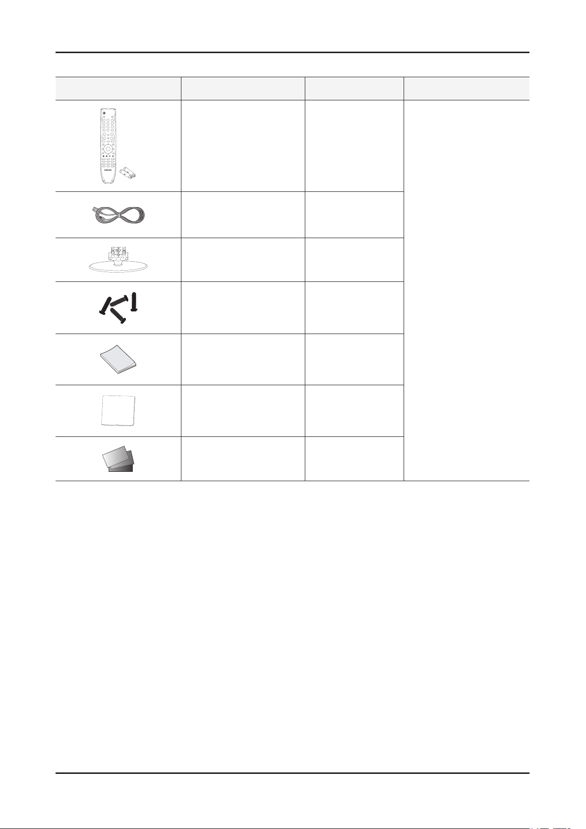
2-4. Accessories
Product Description Code. No Remark
Remote Control & Batteries
(AAA x 2)
Power Cord 3903-000456
Stand
Screws
(for the stand - M4)
Owner’s Instructions BN68-02588A
Cleaning Cloth BN63-01798B
BN59-01005A
19" : BN96-12868B
22" : BN96-12887B
6002-001294
Samsung Electronics
Service center
Warranty Card / Registration
Card / Safety Guide Manual
(Not available in all locations)
-
2-8
3. Disassembly and Reassembly
3. Disassembly and Reassembly
This section of the service manual describes the disassembly and reassembly procedures for the LE19/22C450 LCD TV.
WARNING: This LCD TV contains electrostatically sensitive devices. Use caution when handling these components.
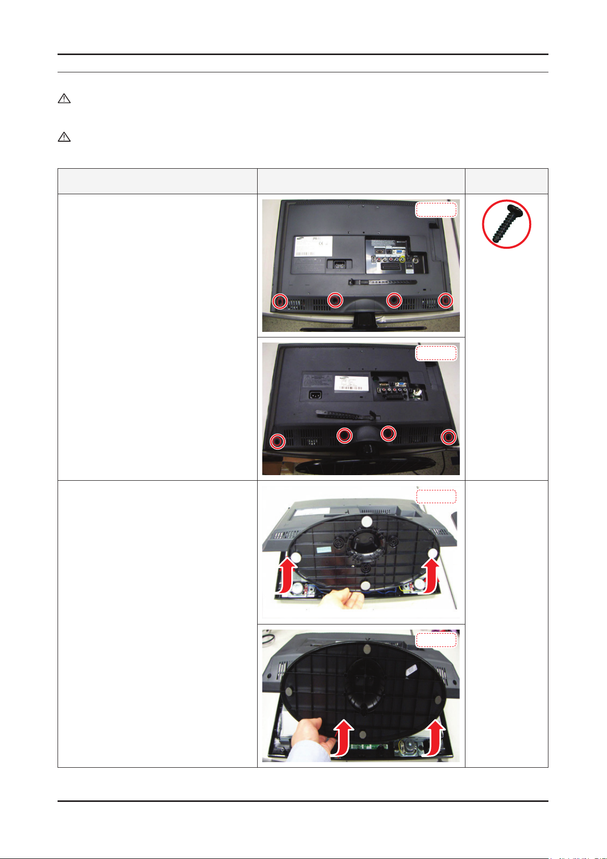
3-1. Disassembly and Reassembly
Cautions: 1. Disconnect the LCD TV from the power source before disassembly.
2. Follow these directions carefully; never use metal instruments to pry apart the cabinet.
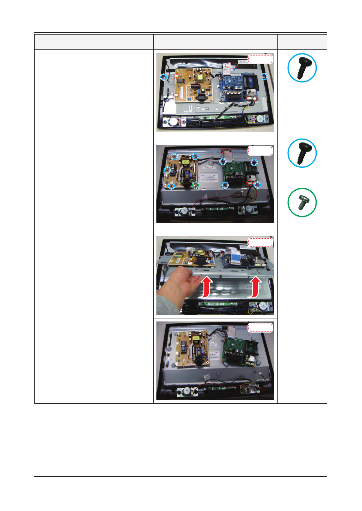
Description Picture Description Screws
1. Place the TV face down on cushioned table.
Remove screws from the stand and back.
19 inch : 4 screws
22 inch : 4 screws
2. Lift up the rear cover.
19 inch
6002-001294
(M4 x L16, Tapping)
22 inch
19 inch
22 inch
3-1
3-2
3. Disassembly and Reassembly
Description Picture Description Screws
3. Remove screws and disconnect conectors.
19 inch : 2 screws
22 inch : 10 screws
19 inch
6003-000269
(M3 x L6, TAPTYPE)
22 inch
6003-000269
(M3 x L6, TAPTYPE)
6003-001439
(M4 x L8, TAPTYPE
4. Lift up the bracket and remove it.
19 inch
22 inch
3-3
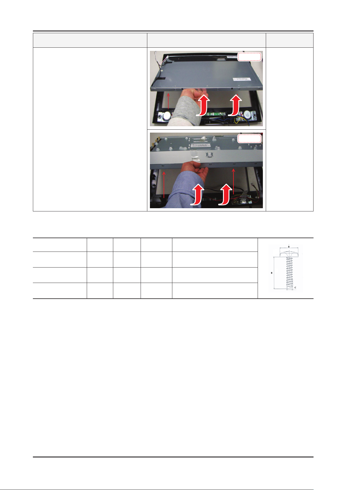
3. Disassembly and Reassembly
Description Picture Description Screws
5. Lift up the panel.
Reassembly procedures are in the reverse order of disassembly procedures. ※
19 inch
22 inch
Screw Size
Code No. A (mm) B (mm) C (mm) Q’ty
6002-001294 8.3±0.5 16±0.8 3.85~4.0 -
6003-000275 5.80~6.30 9.2~10.0 2.85~2.95 -
6003-001439 8.3±0.4 8.0±0.4 3.85~3.93 1(ALL)

4. Troubleshooting
4-1. Troubleshooting
4-1-1. Previous check
Check the various cable connections rst. 1.
• Check to see if there is a burnt or damaged cable.
• Check to see if there is a disconnected or loose cable connection.
• Check to see if the cables are connected according to the connection diagram.
Check the power input to the Main Board.2.
4. Troubleshooting
4-1
4-2
4. Troubleshooting
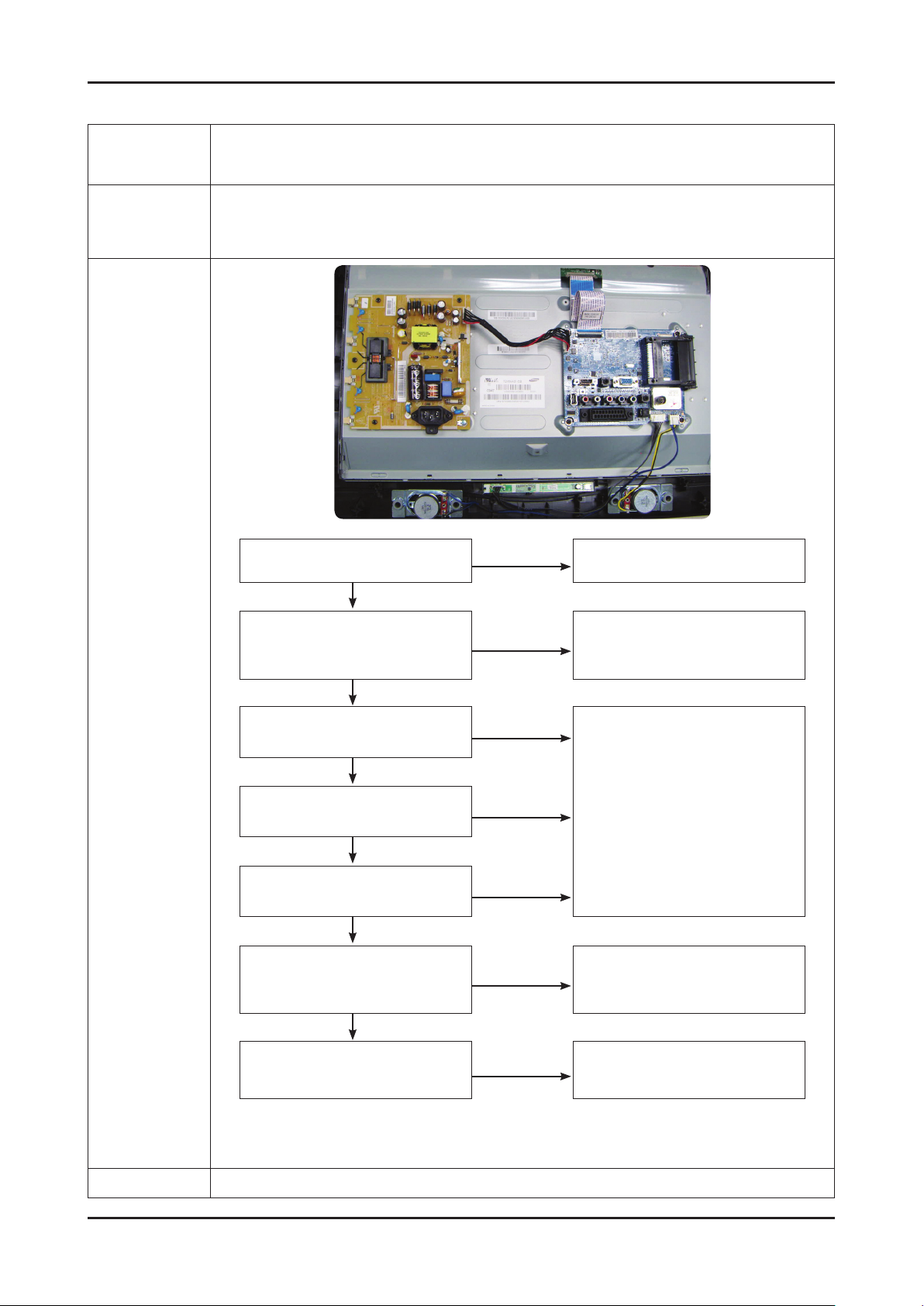
4-1-2. No Power
Symptom
The IP relay or the LEDs on the front panel does not work when connecting the power cord if the cables are
Major
checkpoints
improperly connected or the Main Board or SMPS is not functioning. In this case, check the following:
The LEDs on the front panel do not work when connecting the power cord. The SMPS relay does not work when connecting the power cord. The units appears to be dead. -
Check the internal cable connection status inside the unit. Check the fuses of each part. - Check the output voltage of SMPS. - Replace the Main Board. -
Diagnostics
Lamp(Backlight) Off,
power indicator LED on?
Yes
Does proper Stand-by
DC A5V_PW(A5V_1) and
A13V_PW(A13V1) appear?
Yes
Does proper Main B13V_PW(B13V1),
B5V_PW(B5V1) appear?
Yes
Does proper DC A3.3V(A3.3V1)
appear?
Yes
Does proper B3.3V_PW(B3.3V1),
B1.8V_PW(B1.8V1) appear?
Yes
Does proper PANEL_5V
appear at LVDS connector
Pin#1~5 of T-con B’D?
Yes
No
No
No
No
No
No
Change the power cable or IP board.
Change the IP Board.
Change the Main Board.
Change the LVDS cable.
Caution
A power is supplied to set?
Make sure to disconnect the power before working on the IP board.
No
Check a other function.
(No picture part)
Replace a LCD Panel.

4-3
4. Troubleshooting
LE26/32B45***
Power CN2001
Pin 1 2 3 4 5 6 7 8 9
Dimming out A13V GND GND GND A5V A5V NC Panel Setting
Loading...