


LE32M87BDX
TFT-LCD TV
Chassis GTU32HEN
Model LE32M87BDX
Manual
SERVICE
TFT-LCD TV Fashion Feature
- Luxurious Slim Design
- Supreme Picture Quality
- Supreme Sound Quality
- Supreme Convenience Quality
- Convenience for Users

ii
Copyright
©2007 by Samsung Electronics Co., Ltd.
All rights reserved.
This manual may not, in whole or in part, be copied,
photocopied, reproduced, translated, or converted to
any electronic or machine readable form without prior
written permission of Samsung Electronics Co., Ltd.
LE32M87BDX Service Manual
First edition June 2007.
Printed in Korea.
Trademarks
Samsung is the registered trademark of Samsung
Electronics Co., Ltd.
LE32M87BDX and MacMaster Cable Adapter are
trademarks of Samsung Electronics Co., Ltd.
Macintosh, Power Macintosh are trademarks of Apple
Computer, Inc.
All other trademarks are the property of their respective
owners.

11. Precautions
………………………………………………………………………………………………………………………………………
11-1
1-1 Safety Precautions ……………………………………………………………………………………………………………………… 1-1
1-2 Servicing Precautions …………………………………………………………………………………………………………………… 1-2
1-3 Static Electricity Precautions …………………………………………………………………………………………………………… 1-2
1-4 Installation Precautions ………………………………………………………………………………………………………………… 1-3
2
2. Product specifications
…………………………………………………………………………………………………………………………
22-1
2-1 Fashion Feature…………………………………………………………………………………………………………………………… 2-1
2-2 LE37M87BDX Specifications …………………………………………………………………………………………………………… 2-2
2-3 Spec Comparison ………………………………………………………………………………………………………………………… 2-3
2-4 Option Specification ……………………………………………………………………………………………………………………… 2-4
3
3. Alignments and Adjustments
…………………………………………………………………………………………………………………
33-1
3-1 Service Instruction ………………………………………………………………………………………………………………………… 3-1
3-2 How to Access Service Mode …………………………………………………………………………………………………………… 3-2
3-3 Factory Data ……………………………………………………………………………………………………………………………… 3-3
3-4 Service Adjustment ……………………………………………………………………………………………………………………… 3-11
3-5 Software Upgrade ………………………………………………………………………………………………………………………3-14
4
4. Trouble shooting
………………………………………………………………………………………………………………………………
44-1
4-1 First Checklist for Troubleshooting ……………………………………………………………………………………………………… 4-1
4-2 Checkpoints by Error Mode ……………………………………………………………………………………………………………… 4-2
5
5. Exploded View and Parts List
………………………………………………………………………………………………………………
55-1
5-1 LE32M87BDX Exploded View …………………………………………………………………………………………………………… 5-1
5-2 LE32M87BDX Parts list ………………………………………………………………………………………………………………… 5-2
6
6. Electrical Parts List
……………………………………………………………………………………………………………………………
66-1
6-1 LE32M87BDX Parts List …………………………………………………………………………………………………………………6-1
7
7. Block Diagram
…………………………………………………………………………………………………………………………………
77-1
8. WWiring Diagram
…………………………………………………………………………………………………………………………………
88-1
8-1 Wiring Diagram …………………………………………………………………………………………………………………………… 8-1
8-2 Main Board Layout ……………………………………………………………………………………………………………………… 8-2
8-3 Wiring Diagram (SUB BOARD) ………………………………………………………………………………………………………… 5-3
8-4 SUB BOARD FRCH MJC ADD PCB …………………………………………………………………………………………………… 8-4
8-5 PIN characteristic ………………………………………………………………………………………………………………………… 8-5
8-6 Connector Location and PCB outline figure ……………………………………………………………………………………………8-8
8-7 Output Connector …………………………………………………………………………………………………………………………8-9
Contents

99. Schematic Diagrams
……………………………………………………………………………………………………………………………
99-1
10. OOperating Instructions and Installation
………………………………………………………………………………………………………
110-1
10-1 Front …………………………………………………………………………………………………………………………………… 10-1
10-2 Connection Panel ……………………………………………………………………………………………………………………… 10-2
10-3 Remote Control ………………………………………………………………………………………………………………………… 10-5
10-4 Installing the Stand …………………………………………………………………………………………………………………… 10-6
10-5 Installing the Wall Mount Kit ………………………………………………………………………………………………………… 10-6
1
11. Disassembly and Reassembly
………………………………………………………………………………………………………………
111-1
11-1 Disassembly …………………………………………………………………………………………………………………………… 11-1
11-2 Reassembly …………………………………………………………………………………………………………………………… 11-5
1
12. PCB Diagram
…………………………………………………………………………………………………………………………………
112-1
12-1 Main PCB Layout ……………………………………………………………………………………………………………………… 12-1
12-2 SMPS Board Diagram ………………………………………………………………………………………………………………… 12-2
12-3 Sub Board Diagram …………………………………………………………………………………………………………………… 12-3
12-4 Sub Board Diagram …………………………………………………………………………………………………………………… 12-4
1
13. Circuit Descriptions
…………………………………………………………………………………………………………………………
113-1
13-1 Block description ……………………………………………………………………………………………………………………… 13-1
13-2 Main Block ……………………………………………………………………………………………………………………………… 13-3
13-3 SMPS Board …………………………………………………………………………………………………………………………… 13-4
1
14. Reference Infomation
………………………………………………………………………………………………………………………
114-1
14-1 Technical Terms ……………………………………………………………………………………………………………………… 14-1
14-2 Pin Assignments ……………………………………………………………………………………………………………………… 14-4
14-3 Timing Chart …………………………………………………………………………………………………………………………… 14-7
14-4 Panel Description …………………………………………………………………………………………………………………… 14-11
Contents

Samsung Electronics Co.,Ltd.
416, Maetan-3Dong, Yeongtong-Gu, Suwon City,
Gyeonggi-Do, Korea, 443-742
Printed in Korea
P/N : BN82-00191B-00
URL : http://itself.sec.samsung.co.kr/
- This Service Manual is a property of
Samsung Electronics Co., Ltd.
Any unauthorized use of Manual can be
punished under applicable International
and/or domestic law.
1 Precautions
1-1
1-1-1 Warnings
1. For continued safety, do not attempt to modify the
circuit board.
2. Disconnect the AC power and DC Power Jack before
servicing.
1-1-2 Ser vicing the LCD Monitor
1. When servicing the LCD Monitor Disconnect the AC
line cord from the AC outlet.
2. It is essential that service technicians have an accurate
voltage meter available at all times. Check the
calibration of this meter periodically.
1-1-3 Fire and Shock Hazard
Before returning the monitor to the user, perform the
following safety checks:
1. Inspect each lead dress to make certain that the leads
are not pinched or that hardware is not lodged between
the chassis and other metal parts in the monitor.
2. Inspect all protective devices such as nonmetallic
control knobs, insulating materials, cabinet backs,
adjustment and compartment covers or shields,
isolation resistor-capacitor networks, mechanical
insulators, etc.
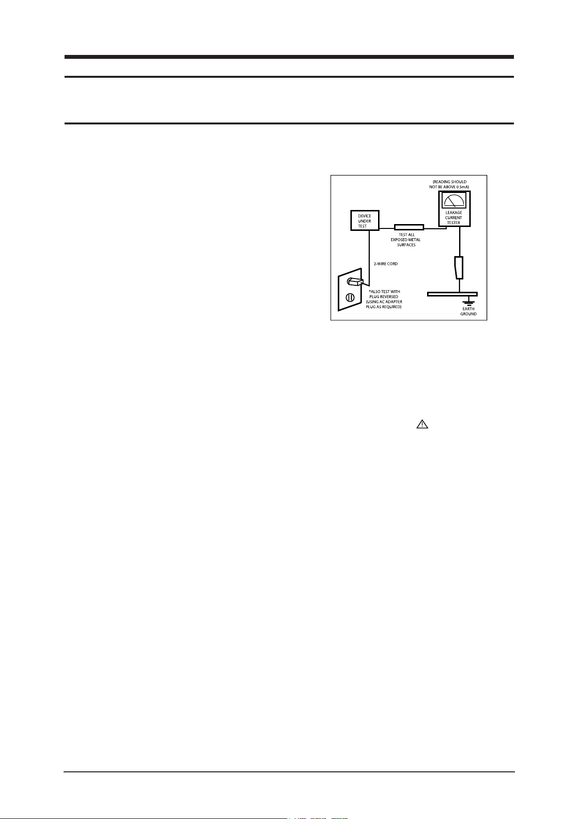
3. Leakage Current Hot Check (Figure 1-1):
WARNING: Do not use an isolation
transformer during
this test.
Use a leakage current tester or a metering system that
complies with American National Standards Institute
(ANSI C101.1, Leakage Current for Appliances), and
Underwriters Laboratories (UL Publication UL1410,
59.7).
Figure 1-1. Leakage Current Test Circuit
1-1-4 Product Safety Notices
Some electrical and mechanical parts have special
safety-related characteristics which are often not evident
from visual inspection. The protection they give may not
be obtained by replacing them with components rated for
higher voltage, wattage, etc. Parts that have special safety
characteristics are identified by on schematics and parts
lists. A substitute replacement that does not have the same
safety characteristics as the recommended replacement part
might create shock, fire and/or other hazards. Product
safety is under review continuously and new instructions
are issued whenever appropriate.
1 Precautions
Follow these safety, servicing and ESD precautions to prevent damage and to protect against potential hazards such as electrical shock.
1-1 Safety Precautions

1 Precautions
1-2
1-2-1 General Ser vicing
Precautions
1. Always unplug the units AC power cord from the AC
power source and disconnect the DC Power Jack
before attempting to:
(a) remove or reinstall any component or assembly, (b)
disconnect PCB plugs or connectors, (c) connect a test
component in parallel with an electrolytic capacitor.
2. Some components are raised above the printed circuit
board for safety. An insulation tube or tape is
sometimes used. The internal wiring is sometimes
clamped to prevent contact with thermally hot
components. Reinstall all such elements to their
original position.
3. After servicing, always check that the screws,
components and wiring have been correctly
reinstalled. Make sure that the area around the
serviced part has not been damaged.
1. Immediately before handling any semiconductor
components or assemblies, drain the electrostatic
charge from your body by touching a known earth
ground. Alternatively, wear a discharging wrist-strap
device. To avoid a shock hazard, be sure to remove the
wrist strap before applying power to the monitor.
2. After removing an ESD-equipped assembly, place it
on a conductive surface such as aluminum foil to
prevent accumulation of an electrostatic charge.
3. Do not use freon-propelled chemicals. These can
generate electrical charges sufficient to damage ESDs.
4. Use only a grounded-tip soldering iron to solder or
desolder ESDs.
5. Use only an anti-static solder removal device. Some
solder removal devices not classified as anti-static
can generate electrical charges sufficient to damage
ESDs.
4. Check the insulation between the blades of the AC
plug and accessible conductive parts (examples: metal
panels, input terminals and earphone jacks).
5. Insulation Checking Procedure: Disconnect the power
cord from the AC source and turn the power switch
ON. Connect an insulation resistance meter (500 V) to
the blades of the AC plug.
The insulation resistance between each blade of the
AC plug and accessible conductive parts (see above)
should be greater than 1 megohm.
6. Always connect a test instruments ground lead to the
instrument chassis ground before connecting the
positive lead; always remove the instruments ground
lead last.
6. Do not remove a replacement ESD from its protective
package until you are ready to install it. Most
replacement ESDs are packaged with leads that are
electrically shorted together by conductive foam,
aluminum foil or other conductive materials.
7. Immediately before removing the protective material
from the leads of a replacement ESD, touch the
protective material to the chassis or circuit assembly
into which the device will be installed.
Caution: Be sure no power is applied to
the chassis or circuit and
observe all other safety
precautions.
8. Minimize body motions when handling unpackaged
replacement ESDs. Motions such as brushing clothes
together, or lifting your foot from a carpeted floor can
generate enough static electricity to damage an ESD.
1-3 Static Electricity Precautions
Some semiconductor (solid state) devices can be easily damaged by static electricity. Such components are commonly called
Electrostatically Sensitive Devices (ESD). Examples of typical ESD are integrated circuits and some field-effect transistors.
The following techniques will reduce the incidence of component damage caused by static electricity.
1-2 Ser vicing Precautions
WARNING: An electrolytic capacitor installed with the wrong polarity might explode.
Caution: Before servicing units covered by this service manual, read and follow the Safety
Precautions section of this manual.
Note: If unforeseen circumstances create conflict between the following servicing precautions and any of the safety
precautions, always follow the safety precautions.

1. For safety reasons, more than two people are
required for carrying the product.
2. Keep the power cord away from any heat emitting
devices, as a melted covering may cause fire or
electric shock.
3. Do not place the product in areas with poor
ventilation such as a bookshelf or closet. The
increased internal temperature may cause fire.
4. Bend the external antenna cable when connecting
it to the product. This is a measure to protect it
from being exposed to moisture. Otherwise, it
may cause a fire or electric shock.
5. Make sure to turn the power off and unplug the
power cord from the outlet before repositioning
the product. Also check the antenna cable or the
external connectors if they are fully unplugged.
Damage to the cord may cause fire or electric
shock.
6. Keep the antenna far away from any high-voltage
cables and install it firmly. Contact with the highvoltage cable or the antenna falling over may
cause fire or electric shock.
7. When installing the product, leave enough space
(10cm) between the product and the wall for
ventilation purposes.
A rise in temperature within the product may
cause fire.
1 Precautions
1-3
1-4 Installation Precautions

Memo
1 Precautions
1-4

2 Product Specifications
2-1
2 Product specifications
2-1 Fashion Feature
Improve Spreker and Bass Sound
- High Frequency sound improve with Reflection Speaker
- 2.2Ch Dome Speaker
- Parametric EQ
Connectivity
- 3 HDMI
Auto Wall Mount
- Set Position Control by Remote Control
Best Picture Quality
- High Contrast Ratio
- High Clarity
- Anti Reflection
Movie Plus
- Film Judder Cancel fucntion
Detailed Settings
- Detail Setting for professional and magazine at Movie mode
HDMI JustScan and PC Support
- Just Scan at HDMI Mode for correct picture size
- PC Timming Support at HDMI Mode
SRS TruSurround XT
- SRS TruSurround XT provides a virtual Dolby surround system.

2 Product Specifications
2-2
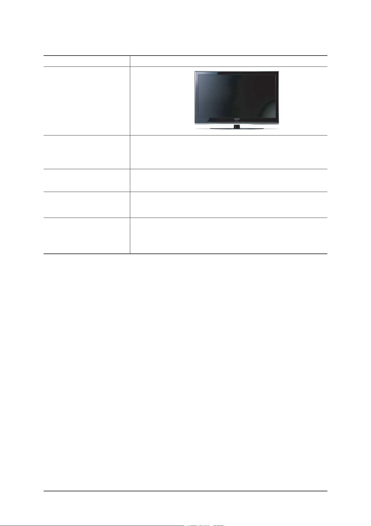
2-2 LE32M87BDX Specifications
Item
LCD Panel
Scanning Frequency
Display Colors
Description
AMVA 92%,120Hz,32inch, 760.0 x 450.0 x 45 pixel pitch
Horizontal : 30 kHz ~ 80 kHz (Automatic) / Vertical : 56 Hz ~ 75 Hz (Automatic)
16.7 M colours
Analog 0.7 Vp-p ±5% positive at 75Ω , internally terminated
Maximum Resolution
Input Video Signal
166.8 MHz
Maximum Pixel Clock rate
AC 220 ~ 240V, 50 ~ 60 Hz
AC power voltage & Frequencya
10 W x 2
Power Consumption
75Ω
Antenna Input
-MAX Internal speaker Out : Right => 10W, Left => 10W
-BASS Control Range : -8 dB ~ + 8dB
-TREBLE Control Range : -8 dB ~ +8 dB
-Headphone Out : 10 mW MAX
-Output Frequency : RF : 80 Hz ~ 15 kHz
A/V : 80 Hz ~ 20 kHz
Sound Characteristic
TV System
Environmental Considerations
Tuning
System
Sound
Frequency Synthesize
PAL, SECAM
MONO, STEREO, NICAM
14 kg
Weight
Set(After installation Stand)
797 x 79 x 531mm ( Wthout stand )
797 x 252 x 579mm ( After installation Stand )
Operating Temperature : 50°F ~ 104°F (10°C ~ 40°C)
Operating Humidity : 10 % ~ 80 %
Storage Temperature : -4°F ~ 113°F (-20°C ~ 45°C)
Storage Humidity : 5 % ~ 95 %
Dimensions(W x D x H)
Set
697.68 (H) mm / 392.26 (V) mm
Active Display
Horizontal/Vertical
Horizontal : 1366 Pixels
Vertical : 768 Pixels
Input Sync Signal
Type : Seperate H/V
Level : TTL level
2 Product Specifications
2-3
LE32M87BDXModel
Design
Frequency
Horizontal
Vertical
Display Color
30 ~ 61 kHz
100 ~ 120 Hz
16.7 M colours
PC Resolution
Maximum mode
Input Signal
Sync Signal
Video Signal
Power Consumption
Normal
Power Saving
150 W
< 1W
H/V Separate, TTL, P. or N.
0.7 Vp-p @ 75ohm
WXGA, 1366 x 768 @ 60 Hz
2-3 Spec Comparison
2 Product Specifications
2-4
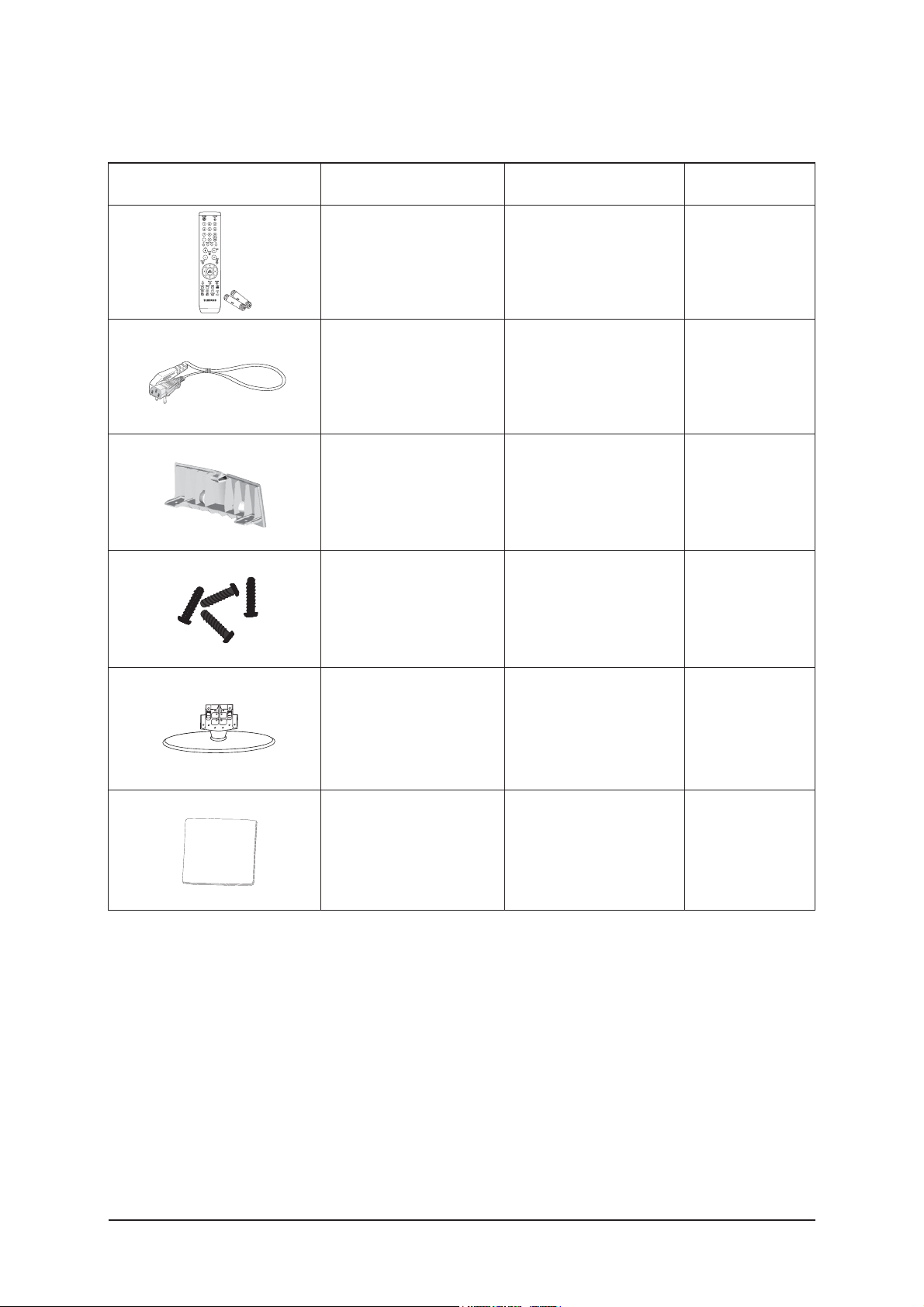
2-4 Option Specification
Item Item Name
Remote Control
&
Batteries (AAA x 2)
Power Cord
Cover-Bottom
Stand Screw
X 4
BN59-00603A
3903-000145
BN63-03103A
BN96-01800A
Code.No Remark
Stand
BN90-01149A
Cleaning Cloth
BN63-01798A

3 Alignments and Adjustments
3-1
3 Alignments and Adjustments
3-1 Ser vice Instr uction
1. Usually, a color TV-VCR needs only slight touch-up adjustment upon installation.
Check the basic characteristics such as height, horizontal and vertical sync.
2. Use the specified test equipment or its equivalent.
3. Correct impedance matching is essential.
4. Avoid overload. Excessive signal from a sweep generator might overload the front-end
of the TV. When inserting signal markers, do not allow the marker generator to distort
test result.
5. Connect the TV only to an AC power source with voltage and frequency as specified on
the backcover nameplate.
6. Do not attempt to connect or disconnect any wire while the TV is turned on. Make sure
that the power cord is disconnected before replacing any parts.
7. To protect aganist shock hazard, use an isolation transform.
3 Alignments and Adjustments
3-2
3-2 How to Access Service Mode
3-2-1 Entering Factory Mode
1. To enter "Service Mode" Press the remote -control keys in this sequence :
- If you do not have Factory remote - control
- If you have Factory remote - control
- The buttons are active in the service mode.
1. Remote - Control Key : Power, Arrow Up, Arrow Down, Arrow Left
Arrow Right, Menu, Enter, Number Key(0~9)
2. Function - Control Key : Power, CH +, CH -, VOL +, VOL -,
Menu, TV/VIDEO(Enter)
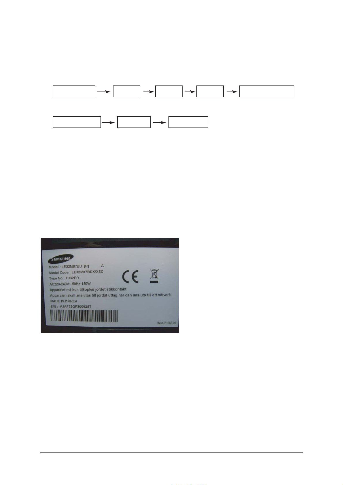
3-2-2 Panel Check
You have to check Panel Maker Because of different adjustments as follows.
First of all, Check the label rating!
1) Label Rating File
- LCD PANEL MARK A:ACER(AUO) S : SEC C : CMO * If not printed you could consider S(sec) panel mark.
2) If Panel Mark is "A", Set the factory mode indicating as follows.
* Option Byte
1. Inch Option 32"
2. Panel Vender AUO_EXT_N
3. Panel Type 32"AU 100
Others are same shown below.
Power OFF Power OnMUTE
PICTURE ON DISPLAY FACTORY
MENU MUTE
3 Alignments and Adjustments
3-3
3-3 Factory Data
1. Calibration
2. Option Table(Service)
3. White Balance
4. SVP-UX
5. Option Block
6. SGTV5810/NTP3000
7. YC Delay
8. Option Table
9. I2C Check
10. W/B MOVIE
11. Checksum
12. Reset
13. Spread Spectrum
T-TLP32PEUD-xxxx (Main Micom Ver)
T-BDPMPEUS-xxxx
BORD2_CALLA_TR-xxxx
Month / Day / Year / Hour / Min. / Sec.
1. Calibration
1) AV Calibration
2) COMP Calibration
3) PC Calibration
4) HDMI Calibration
5) DTV Calibration
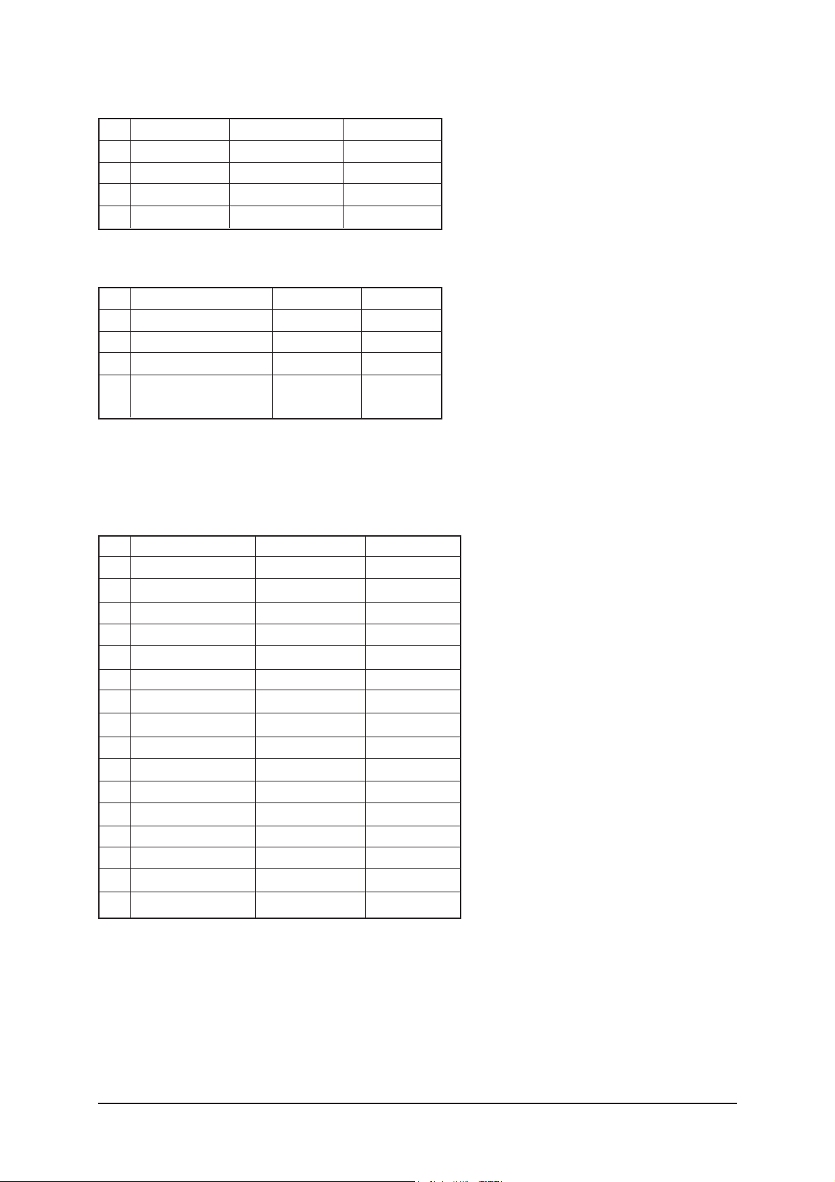
2. Option Table XXXX XXXX
No
Item
1
2
3
4
5
6
7
8
9
10
11
12
13
14
15
16
17
18
19
Ready
Inch Option
Panel Vender
DDR
Panel Type
Model Option
Anynet +
Light Effect
WM Calib
Auto Power
LNA Menu
TTX On/Off
TTX List
Carrier Mute
High Deviation
VOL.Curve
HDMI Hotplug
HDMI Clock CtrI
HDMI Hotplug Dly
ON/OFF
23"/ 26" / 32"...
AUO/CMO...
ETRON/SAMSUNG
32"AU_100/37"CPT.....
Calla/Lily/Bord Plus/Jasmine
ON/OFF
ON/OFF
ON/OFF
ON/OFF
ON/OFF
ON/OFF
Flof/List
ON/OFF
ON/OFF
Small/Large
1/0
1/0
3~50
OFF
32"
AUO_EXT_N
ETRON
32"AU_100
BDP/TLP
ON
OFF
OFF
ON
ON
ON
Flof
OFF
OFF
Large
1
1
9
Range
3 Alignments and Adjustments
3-4
No
Item
20
21
22
23
24
25
26
27
Hotel Option
Hotel Mode
Power On Channel
Power On Volume
Max Volume
Local Key Lock
Power On Source
Shop Mode
Color Space
PC Ident
Language
Ch.Table
TTX Group
Nordic
ON/OFF
1~99
1~100
1~100
ON/OFF
RF/Ext.1...
ON/OFF
ON/OFF
ON/OFF
English/German...
SUWON/SESK/SEH/TTSEC
Auto/West Europe...
ON/OFF
OFF
1
10
100
OFF
RF
OFF
ON
ON
English
SUWON
Auto
ON
Range
3. White Balance
No
Item Range
1
2
3
4
5
6
7
8
Sub-Briteness
R-offset
G-offset
B-offset
Sub-Contrast
R-Gain
G-Gain
B-Gain
00H~FFH
00H~FFH
00H~FFH
00H~FFH
00H~FFH
00H~FFH
00H~FFH
00H~FFH
128
128
128
128
128
128
128
128
128
128
128
128
128
128
128
128
128
128
128
128
128
128
128
128
128
128
128
128
128
128
128
128
TV/AV/Scart Comp/iDTV PC
HDMI
4. SVP-PX
1) ComB Filter
2) Sharpness
No1Item
Y-Filter
Range
00H~FFH
No
1
2
3
4
5
6
7
8
9
10
11
Item
H2Gain
H4Gain
V2Gain
V4Gain
Sr2Gain
Sr4Gain
Sl2Gain
Sl4Gain
Peakth1
Peakth2
Peskth3
Range
00 ~ 1FH
00 ~ 1FH
00 ~ 1FH
00 ~ 1FH
00 ~ 1FH
00 ~ 1FH
00 ~ 1FH
00 ~ 1FH
00H~FFH
00H~FFH
00H~FFH
RF
05H
04H
0CH
0CH
00H
00H
00H
00H
06H
2FH
3FH
AV
05H
0AH
0CH
10H
00H
02H
00H
02H
02H
2FH
3FH
HDMI
0AH
0AH
10H
10H
00H
04H
00H
04H
03H
2FH
3FH
PC
05H
05H
0AH
0AH
00H
02H
00H
02H
08H
2FH
3FH
iDTV
05H
05H
0AH
0AH
00H
02H
00H
02H
04H
2FH
3FH
Comp480i
05H
05H
0AH
0CH
00H
00H
00H
00H
03H
2FH
3FH
Comp480p
05H
05H
0CH
0CH
00H
00H
00H
00H
03H
2FH
3FH
Comp720p
04H
02H
0AH
0AH
00H
02H
00H
02H
03H
2FH
3FH
Comp1080i
04H
02H
0AH
0AH
00H
02H
00H
02H
03H
2FH
3FH
3 Alignments and Adjustments
3-5
3) NR
4) RGB Calibration
5) ADC Calibration
6) Calibration Target
No
1
2
3
4
Item
Y_NR_OFF
C_NR_OFF
Y_NR_ON
C_NR_ON
Range
00H~FFH(Y_NR_OFF)
00H~FFH(C_NR_OFF)
00H~FFH(Y_NR_ON)
00H~FFH(C_NR_ON)
00H
00H
00H
00H
No
Item Range
1
2
3
4
5
6
R-Offset
G-Offset
B-Offset
R-Gain
G-Gain
B-Gan
00H~FFH
00H~FFH
00H~FFH
00H~FFH
00H~FFH
00H~FFH
3AH
3AH
3AH
A6H
A6H
A6H
40H
40H
40H
92H
92H
92H
32H
32H
32H
A9H
A9H
A9H
82H
82H
82H
6CH
6CH
6CH
TV/AV/S_Video Component PC
HDMI
No
Item Range
1
2
3
4
AV ADC
COMP ADC
PC ADC
ALL RGB
00H~FFH
00H~FFH
00H~FFH
00H~FFH
10H
10H
10H
01H
DCH
EBH
DCH
EBH
02H
02H
04H
0AH
low high Delta
No
Item Range
1
2
3
4
5
6
7
8
9
10
11
12
13
TCD3 Contrast
TCD3 Brightness
TCD3 CR
TCD3 CB
TCD3 Delay
Analog Y Offset
Analog PB Offset
Analog PR Offset
Analog Y Gain
Analog PB Gain
Analog PR Gain
Black Level
Svp Brightness
00H~FFH
00H~FFH
00H~FFH
00H~FFH
00H~FFH
00H~FFH
00H~FFH
00H~FFH
00H~FFH
00H~FFH
00H~FFH
00H~FFH
00H~FFH
79H
29H
80H
80H
00H
40H
80H
80H
D6H
80H
80H
00H
00H
78H
20H
80H
80H
00H
3DH
80H
80H
B3H
B3H
B3H
00H
00H
78H
20H
80H
80H
00H
44H
44H
44H
A4H
ACH
A7H
00H
00H
78H
20H
80H
80H
00H
40H
80H
80H
80H
80H
80H
00H
00H
TV/AV/S_Video Component PC
HDMI
3 Alignments and Adjustments
3-6
5. Option Block
7) Color Management
1) FRC(Micronas)
2) FRC2X
No
Item Range
1
2
3
4
Skin Direction
Skin Enhance
Green Stretch
Blue Stretch
Reddish/Yellowish
00H~FFH
00H~FFH
00H~FFH
Reddish
00H
00H
00H
8) Sync Control
No
Item Range
1
2
3
4
5
HSync Tip End
VSync AGC Min
VSync AGC Max
VSync Clamp mode
VSync Thresh
00H~FFH
00H~FFH
00H~3FH
0~3
00H~FFH
Reddish
00H
00H
0
00H
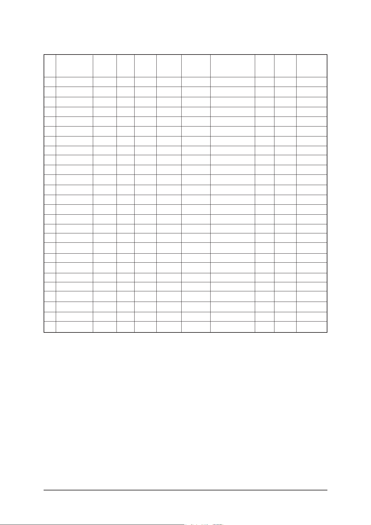
No
Item Range
1
2
3
4
5
6
7
8
9
10
11
12
13
14
15
16
OUTCON
GAMMA
OCC_MODE
FALLBACK
DBG_MARK
SPR_CBR
BIT_EXPAND
INV_BIT_EXPAND
REPEAT_MODE
DEMO_ON_OFF
MMU_RD_START
ME_RD_START
MC_RD_START
CMZL(0x36E)
BLOL(0x2A7)
LOGO(0x2A7)
1~3
1~7
0/1
0/1
0/1
0/1
0/1
0/1
0/1
0/1
00H~FFH
00H~FFH
00H~FFH
00H~0FH
00H~0FH
00H~0FH
0
0
0
0
0
0
0
0
0
0
00H
00H
00H
0H
0H
0H
3 Alignments and Adjustments
3-7
1
2
3
4
5
6
7
8
9
10
11
12
13
14
15
16
17
18
19
20
21
22
23
24
25
26
Pattern Select
BS-On
B-Slope Gain
B-Tilt Min
B-Tilt Max
B-Tilt Slope
LFunc-Basis
Hfunc-Basis
Mean-Offset1
Mean Offset2
Mean Slope
Input Offset
Input Gain
ACR Offset
ACR Th1
ARC Th2
Skin Enable
Skin Tu
Skin Tv
M Skin Tu
M Skin TV
Sub Color
M-Au-Sub Color
M-Wi-Sub Color
MW-Skin-Tu
MW-Skin-Tv
0~20
0/1
0~255
0~255
0~255
0~255
0~255
0~255
0~255
0~255
0~255
0~255
0~255
0~128
0~255
0~255
0/1
0~255
0~255
0~255
0~255
0~255
0~255
0~255
0~255
0~255
0
1
70
30
130
128
75
80
50
220
93
128
128
10
10
110
1
128
128
110
110
128
133
128
128
128
0
1
44
20
120
128
20
40
100
200
56
128
128
15
30
130
1
165
140
128
128
128
128
128
128
128
0
1
44
20
120
128
20
40
100
200
56
128
128
15
30
130
1
165
140
128
128
128
128
128
128
128
3) FBE2
No Item Range
0
1
64
20
120
128
55
65
75
225
85
128
128
15
30
130
1
165
128
128
128
150
128
128
128
128
HDMI
0
1
64
20
120
128
75
88
75
225
85
128
128
15
30
130
1
128
128
128
128
143
128
128
128
128
DTV
0
1
64
20
120
128
75
88
75
225
85
128
128
15
30
130
1
128
128
128
128
143
128
128
128
128
DTVRF
AV/
S-VIDEO
COMP
(480i/576i)
0
1
64
20
120
128
40
40
75
155
45
128
128
15
30
130
1
150
140
128
128
135
128
128
128
128
COMP
(480p/576p)
0
1
64
20
120
128
70
75
75
225
85
128
128
15
30
130
1
165
128
128
128
140
128
128
128
128
COMP
(720p/1080i/1080p)
3 Alignments and Adjustments
3-8
4) Pdp Logic
No
Item Range
1
2
3
4
5
6
7
8
9
10
11
12
13
Pattern Srlect
Data updata
Data Type
CDC Sw
CDC Strengh Th
BRE Sw
FRC Repeat Mode
FRC CBG Mark On
ERC Bypass
Panel Type
Panel Inch
Panel Version
Logic Sw Version
0~63
ON/OFF
42"EU MRT/42"EU MESH/.......
ON/OFF
0~31
ON/OFF
ON/OFF
0~15
ON/OFF
-
-
-
-
0
OFF
42"EU MRT
OFF
0
OFF
OFF
0
OFF
0H
SD
0H 0H 0H
6. SGTV5810/NTP3000
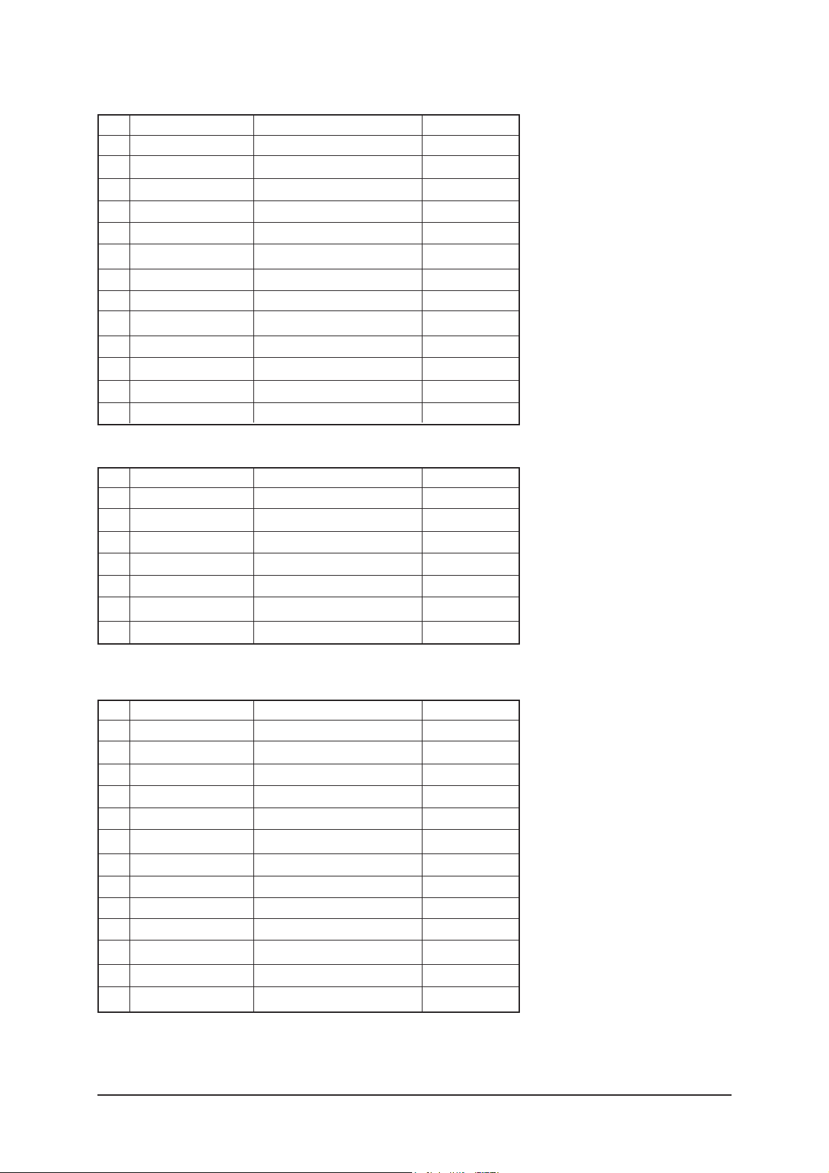
No
Item Range
1
2
3
4
5
6
7
ID Tone Shift
ID Tone Thresh
Demod Prescaler
Master Volume
PWM Modulation
DRC Threshold
Speaker EQ
1H~FH
00H~FFH
00H~20H
00H~30H
80H~F2H
00H~7FH
ON/OFF
01H
7FH
13H
13H
F1H
06H
ON
7. YC Delay
No
Item Range
1
2
3
4
5
6
7
8
9
10
11
12
13
RF PAL-B/G
RF PAL - D/K
RF PAL - I
RF SECAM - B/G
RF SECAM - D/K
RF SECAM -L/L'
RF NTSC 3.58
RF NTSC 4.43
AV PAL
AV SECAM
AV NTSC 3.58
AV NTSC 4.43
AV PAL60
00H~FFH
00H~FFH
00H~FFH
00H~FFH
00H~FFH
00H~FFH
00H~FFH
00H~FFH
00H~FFH
00H~FFH
00H~FFH
00H~FFH
00H~FFH
77H
77H
77H
86H
86H
86H
40H
CCH
64H
CCH
95H
AAH
77H
3 Alignments and Adjustments
3-9
8. Adjust
9. I2C Check
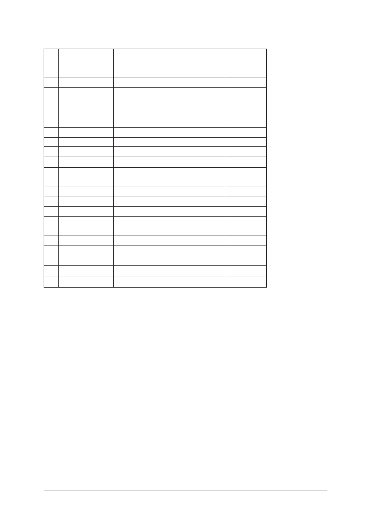
No
Item Range
1
2
3
4
5
6
7
8
9
10
11
12
13
14
15
16
17
18
19
Video Mute Time
Dynamic Contrast
Dynamic Dimming
Dynamic CE
LNA PLUS
RFDB-1 Level
RFDB-2 Level
RFDB-3 Level
RFDB-4 Level
Magazine LNA
PixelShift Test
Debug
ACR
D-Watchdog
Watchdog
URRT Select
FBE Select
Tuner
Tuner Top Semco
Tuner Top ALPS
D. Gamma
M. Gamma
MJC/PDP FRC
0~255
ON/OFF
ON/OFF
ON/OFF
0~255
0~255
0~255
0~255
ON/OFF
ON/OFF
ON/OFF
ON/OFF
ON/OFF
ON/OFF
MAIN / IDTV / PDP Lvds ON / PDP Lvds OFF
FBE2X/FBE2
Auto/ALPS/Semco
1-31
1-31
s_1-10 /0_85/off
s_1-10 /0_85/off
All On/All_off/MJC OnlyFRC Only
10
ON
ON
OFF
2
5
7
24
OFF
OFF
OFF
OFF
ON
ON
OFF
FBE2X
Auto
10
13
s_1
OFF
ALL ON
3 Alignments and Adjustments
3-10
10. W/B MOVIE
1
2
3
4
5
6
7
8
9
10
8
9
10
11
12
13
14
15
16
17
18
19
20
21
22
WB Movie
Color Mode
Color Tone
Msub Brigh
Msub Contr
W1_RGAIN
W1_BGAIN
W1_R_OFFS
W1_B_OFFS
W2_RGAIN
W2_BGAIN
W2_R_OFFS
W2_B_OFFS
NO_RGAIN
NO_BGAIN
NO_R_OFFS
NO_B_OFFS
C2_RGAIN
C2_BGAIN
C2_R_OFFS
C2_B_OFFS
Movie Contr
Movie Brigh
Movie Color
Movie Sharp
ON/OFF
Movie
0~255
0~255
0~255
0~255
0~255
0~255
0~255
0~255
0~255
0~255
0~255
0~255
0~255
0~255
0~255
0~255
0~255
0~255
0~100
0~100
0~100
0~100
No Item Range
OFF
Movie
Cool1
128
128
176
63
131
138
168
46
130
131
152
100
129
130
126
168
128
129
100
45
55
75
TV/AV/S_Video
OFF
Dynamic
Cool1
128
128
161
74
119
140
143
47
127
145
139
102
125
133
122
141
129
127
100
45
55
75
Component
OFF
Dynamic
Cool1
128
128
144
117
127
110
149
93
124
110
137
123
126
114
123
156
117
116
100
45
55
75
PC
OFF
Dynamic
Cool1
128
128
161
76
118
141
142
51
128
143
141
104
121
133
125
143
128
128
100
45
55
75
HDMI
OFF
Dynamic
Cool1
128
128
157
76
119
138
142
48
129
143
141
104
126
136
124
142
128
128
100
45
55
75
Scart1/2
11. Checksum 7A72
12. Reset
13. Spread Spectrun
No
Item Range
1
2
3
4
5
6
7
Spectrum
Delta
Positive
Negative
Speed
Time
FBE Spectrum
ON/OFF
-128 ~ +128
0~99
0~99
0~7
0~7
0~5
ON
0
0
0
0
0
3

3 Alignments and Adjustments
3-11
3-4 Ser vice Adjustment
3-4-1 White Balance - Calibration
If picture color is wrong, do calibration first.
Equipment : CA210, Patten : chess pattern
Execute calibration in Factory Mode
Source AV : PAL composite, Component : 1280*720/60Hz
PC : 1024*768/60Hz
3-4-2 White Balance - Adjustment
If picture color is wrong, check White Balance condition.
Equipment : CA210, Patten : Flat W/B Pattern
Adjust W/B in Factory Mode
Sub brightness and R/G/B Offset controls low light region
Sub contrast and R/G/B Gain controls high light region
Source AV : PAL composite, Component : 1280*720/60Hz
HDMI[DVI] : 1280*720/60Hz
Flat W/B Pattern
[ Test Pattern : MIK K-7256 PAttern #92 ]
*Color temperature
1500K +/-500, -6 ~-20 MPCD
*Color coordinate
H/L : 267/263 +/- 2 35.0 Ft +/- 2.0Ft
L/L : 270/260 +/- 3 1.5 Ft +/- 0.2Ft
( chess patten )
3 Alignments and Adjustments
3-12
3-4-3 Conditions for Measurement
1. On the basis of toshiba ABL pattern : High Light level (57 IRE)
- INPUT SIGNAL GENERATOR : MSPG-925LTH
* Mode NO 2 : 744X484@60 Hz
NO 6 : 1280X720@60 Hz
NO 21 : 1024X768@60 Hz
* Pattern NO 36 : 16 Color Pattern
NO 16 : Toshiba ABL Pattern
2. Optical measuring device : CA210 (FL)
Please use the MSPG-925 LTH generator for model
LE26M51B/LE32M51B/LE40M51B/LE46M51B
.
3-4-4 Method of Adjustment
1. Adjust the white balance of AV, Component and DVI Modes.
(AV Component)
a) Set the input to the mode in which the adjustment will be made
(RF DTV PC DVI).
* Input signal - VIDEO Mode : Model #2 (744*484 Mode), Pattern #16
- DTV,DVI Mode : Model #6 (1280*720 Mode), Pattern #16
- HDMI Mode: Model #6(1280*720 Mode), Pattern #16
b) Enter factory color control, confirm the data.
c) Adjust the low light. (Refer to table 1, 2 in adjustment position by mode)
- Adjust sub - Brightness to set the 'Y' value.
- Adjust red offset ('x') and blue offset ('y') to the color coordinates.
* Do not adjust green offset data.
d) Adjust the high light. (Refer to table 1, 2 in adjustment position by mode)
- Adjust red gain ('x') and blue gain ('y') to the color coordinates.
* Do not adjust the green gain and sub-contrast (Y) data.
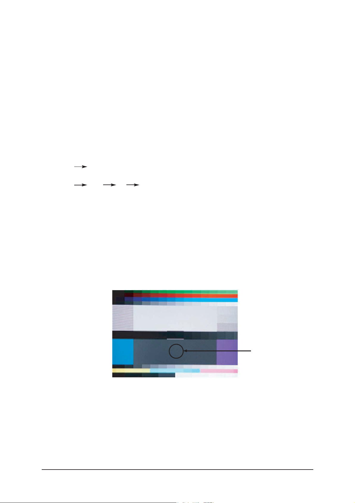
Picture 4-2 Flat W/B Pattern
Low light
Measurement point
3 Alignments and Adjustments
3-13
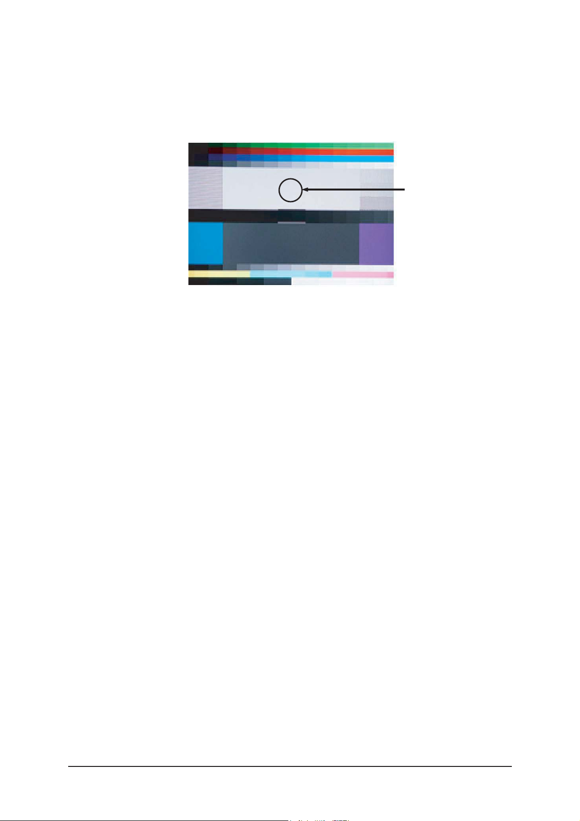
d) Adjust the high light. (Refer to table 1, 2 in adjustment position by mode)
- Adjust red gain ('x') and blue gain ('y') to the color coordinates.
* Do not adjust the green gain and sub-contrast (Y) data.
Picture 4-3 Flat W/B Pattern
High light
Measurement point
3 Alignments and Adjustments
3-14
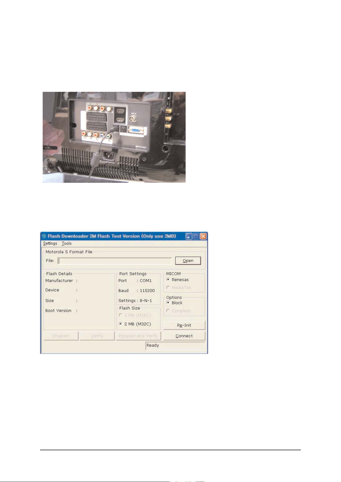
3-5 Software Upgrade
3-5-1 How to Update Flash ROM
1. Install the Flash Downloader
ConnectSet(Service Jack)and Jig Cable to execute Program Update.
2. Flash Downloader program update
-Before Turning on the set,Click "connect"which is under of OSD Screen!
-Turn on the Set.

4 Troubleshooting
4-1
4 Troubleshooting
4-1 First Checklist for Troubleshooting
1. Check the various cable connections first.
- Check to see if there is a burnt or damaged cable.
- Check to see if there is a disconnected cable connection or a connection is too loose.
- Check to see if the cables are connected according to the connection diagram.
2. Check the power input to the Main Board.
3. Check the voltage in and out between the SMPS Main Board, between the SMPS
INVERTER Board, and between the Main LVDS Boards.
4 Troubleshooting
4-2
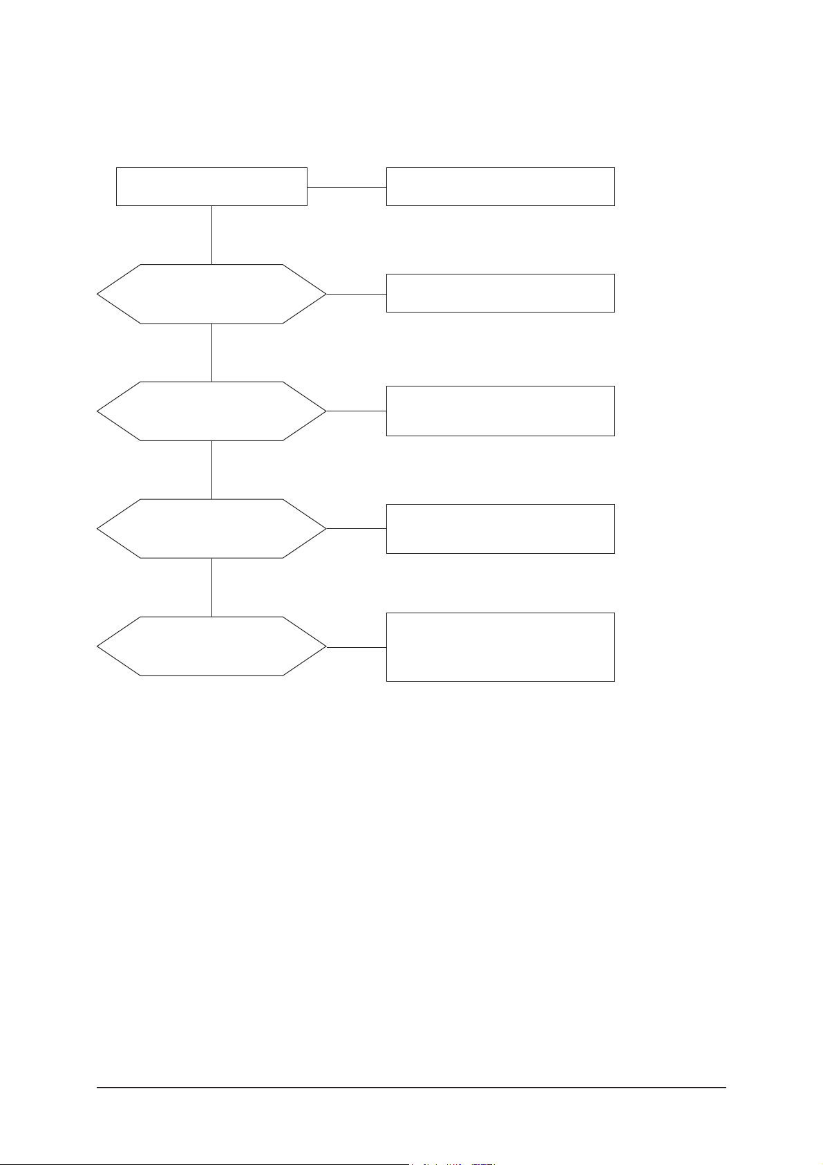
4-2-1 No Power
4-2 Checkpoints by Error Mode
Does proper DC 13V
appear at JP845?
Change a Assy PCB Power.
Yes
Yes
No
Check a connection a power cable.
No
Does proper DC A3.3V,
A5V appear at
C1158, C1150?
Check a IC1112, Q1103.
Change a main PCB ass'y.
Yes
No
Does proper DC 5V, 3.3V,
1.2V appear at C1153, C1178,
C1170?
Check a IC1111, IC1102, IC1113.
Change a main PCB ass'y
Yes
A power is supplied to set?
Check a other function.
(No picture part)
Replace a lcd panel.
No
No
LAMP off, power indicator
LED red color?
TIP: How to drive the circuit by force when LCD panel Lamp is faulty.
- It is available to drive the circuit when the pin of 2 in Main_Power_control CN1101
connect the pin of 4.
4 Troubleshooting
4-3
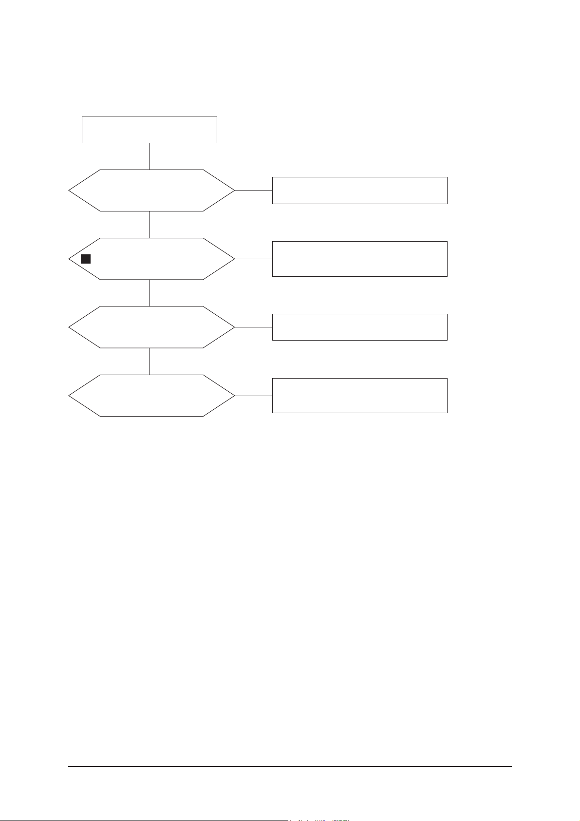
4-2-2 No Video (Analog PC)
Check a PC source and check
the connection of DSUB cable?
Input a analog PC signal and
connected cable(DPMS).
Yes
Does the signal appear at
C2078,C2077,C2079(R, G, B)
of IC2001?
PC cable. Change a PC
cable. Change a main PCB ass'y.
Yes
Power Indicator is off.
Lamp on, no video.
No
No
1
Does the digital data appear
at the output of
LVDS (RA2008~2013)?
Check a IC2001
Change a main PCB ass'y.
Yes
Check a LVDS cable?
Replace a lcd panel?
Please, Call to Samsung Co. LTD.
Yes
No
No
 Loading...