


DVD PLAYER
BASIC : DVD-E360
Application Model : DVD-E360
Application Area : BAS,EN,HC,KE,PE,RU,SH,SJ,SQ,
SW,TK,UM,XA,XD,XE,XL,XN,XS,
XU,XV,ZA,ZC,ZF,ZN,ZS,ZX
SERVICEMANUAL
DVD PLAYER |
|
Contents |
1. Precautions
2. Product Specifications
3. Disassembly and Reassembly
4. Troubleshooting
5. PCB Diagrams
6. Schematic Diagrams
Refer to the service manual in the GSPN (see the rear cover) for more information.

Contents
Contents
1. |
Precautions ...................................................................................................................................... |
|
1 |
− |
1 |
|
|
1.1. |
Safety Precautions ................................................................................................................... |
1 |
− |
1 |
|
|
1.2. |
Servicing Precautions ............................................................................................................... |
1 |
− |
3 |
|
|
|
1.2.1. |
General Servicing Precautions ....................................................................................... |
1 |
− |
3 |
|
|
1.2.2. |
Insulation Checking Procedure....................................................................................... |
1 |
− |
3 |
|
1.3. |
ESD Precautions...................................................................................................................... |
1 |
− |
4 |
|
|
1.4. Handling the optical pick-up ...................................................................................................... |
1 |
− |
5 |
||
2. |
Product Specifications........................................................................................................................ |
2 |
− |
1 |
||
|
2.1. |
Product Specification................................................................................................................ |
2 |
− |
1 |
|
|
|
2.1.1. |
DVD General Features ................................................................................................. |
2 |
− |
2 |
|
|
2.1.2. Discs which cannot be played with this player................................................................... |
2 |
− |
2 |
|
|
|
2.1.3. Disc Type and Characteristics ........................................................................................ |
2 |
− |
2 |
|
|
|
2.1.4. |
Region Code............................................................................................................... |
2 |
− |
3 |
|
|
2.1.5. |
USB.......................................................................................................................... |
2 |
− |
4 |
|
2.2. |
Chassis Product Specification..................................................................................................... |
2 |
− |
6 |
|
|
2.3. |
Option Product Specification...................................................................................................... |
2 |
− |
7 |
|
3. |
Disassembly and Reassembly .............................................................................................................. |
3 |
− |
1 |
||
|
3.1. |
Cabinet and PCB ..................................................................................................................... |
3 |
− |
1 |
|
|
|
3.1.1. |
Top Cabinet Removal................................................................................................... |
3 |
− |
1 |
|
|
3.1.2. Assy Front Cabinet Removal ......................................................................................... |
3 |
− |
2 |
|
|
|
3.1.3. |
Assy Loader Removal .................................................................................................. |
3 |
− |
3 |
|
|
3.1.4. Main PCB and S.M.P.S PCB and RCA Jack PCB Removal.................................................. |
3 |
− |
4 |
|
|
3.2. |
PCB Location ......................................................................................................................... |
3 |
− |
5 |
|
4. |
Troubleshooting................................................................................................................................ |
4 |
− |
1 |
||
|
4.1. |
Troubleshooting ...................................................................................................................... |
4 |
− |
1 |
|
|
4.2. |
Software Update...................................................................................................................... |
4 |
− 25 |
||
|
|
4.2.1. |
CD Upgrade ............................................................................................................... |
4 |
− 25 |
|
|
|
4.2.2. Main F_W Upgrade Method.......................................................................................... |
4 |
− 29 |
||
5. |
PCB Diagrams.................................................................................................................................. |
|
5 |
− |
1 |
|
|
5.1. |
Wiring Diagram....................................................................................................................... |
5 |
− |
2 |
|
|
5.2. |
Main PCB .............................................................................................................................. |
5 |
− |
3 |
|
|
5.3. |
S.M.P.S PCB........................................................................................................................... |
5 |
− |
6 |
|
|
5.4. |
RCA Jack PCB........................................................................................................................ |
5 |
− |
8 |
|
6. |
Schematic Diagrams .......................................................................................................................... |
6 |
− |
1 |
||
|
6.1. |
All Block Diagram................................................................................................................... |
6 |
− |
2 |
|
|
6.2. |
Power.................................................................................................................................... |
|
6 |
− |
3 |
|
|
6.2.1. About S.M.P.S (Ringing Choke Converter Method)............................................................ |
6 |
− |
3 |
|
|
|
6.2.2. Circuit descripcotion [FLY-Back RCC(Ringing Choke Converter)] Control ............................ |
6 |
− |
3 |
|
i |
Copyright© 1995-2011 SAMSUNG. All rights reserved. |

|
|
Contents |
|
|
6.2.3. Internal Block Diagram (Internal Block Diagram of S.M.P.S Circuit) |
.................................... 6 − |
5 |
6.3. |
S.M.P.S (S.M.P.S PCB)............................................................................................................. |
6 − |
6 |
6.4. |
Video (Main PCB) ................................................................................................................... |
6 − |
7 |
6.5. |
Audio (Main PCB)................................................................................................................... |
6 − |
8 |
6.6. |
Decoder (Main PCB)................................................................................................................ |
6 − |
9 |
Copyright© 1995-2011 SAMSUNG. All rights reserved. |
ii |
1. Precautions
1. Precautions
1.1. Safety Precautions
1)Before returning an instrument to the customer, always make a safety check of the entire instrument, including, but not limited to, the following items:
a)Be sure that no built-in protective devices are defective or have been defeated during servicing
i)Protective shields are provided to protect both the technician and the customer. Correctly replace all missing protective shields, including any removed for servicing convenience.
ii)When reinstalling the chassis and/or other assembly in the cabinet, be sure to put back in place all protective devices, including, but not limited to, nonmetallic control knobs, insulating fish papers, adjustment and compartment covers/shields, and isolation resistor/capacitor networks. Do not operate this instrument or permit it to be operated without all protective devices correctly installed and functioning.
b)Be sure that there are no cabinet openings through which adults or children might be able to insert their fingers and contact a hazardous voltage. Such openings include, but are not limited to, excessively wide cabinet ventilation slots, and an improperly fitted and/or incorrectly secured cabinet back cover.
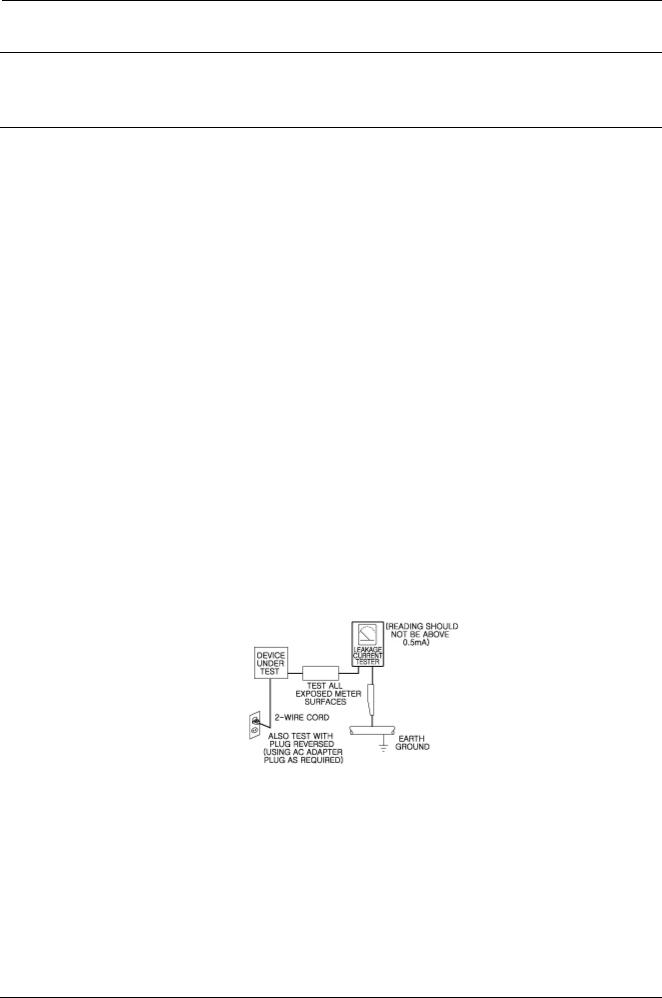
c)Leakage Current Hot Check — With the instrument completely reassembled, plug the AC line cord directly into a 230V(220V ~ 240V) AC outlet. (Do not use an isolation transformer during this test.)
Use a leakage current tester or a metering system that complies with American National Standard Institute (ANSI) C101.1 Leakage Current for Appliances and Underwriters Laboratories (UL) 1270 (40.7). With the instrument’s AC switch first in the ON position and then in the OFF position, measure from a known earth ground (metal water pipe, conduit, etc.) to all exposed metal parts of the instrument (antennas, handle brackets, metal cabinets, screwheads, metallic overlays, control shafts, etc.), especially any exposed metal parts that offer an electrical return path to the chassis.
Any current measured must not exceed 0.5mA.
Reverse the instrument power cord plug in the outlet and repeat the test. See
Any measurements not within the limits specified herein indicate a potential shock hazard that must be eliminated before returning the instrument to the customer.
Fig. 1-1 AC Leakage Test
1-1 |
Copyright© 1995-2011 SAMSUNG. All rights reserved. |

1. Precautions
d)Insulation Resistance Test Cold Check — (1) Unplug the power supply cord and connect a jumper wire between the two prongs of the plug. (2) Turn on the power switch of the instrument. (3) Measure the resistance with an ohmmeter between the jumpered AC plug and all exposed metallic cabinet parts on the instrument, such as screwheads, antenna, control shafts, handle brackets, etc. When an exposed metallic part has a return path to the
chassis, the reading should be between 1 and 5.2 megohm. When there is no return path to the chassis, the reading must be infinite. If the reading is not within the limits specified, there is the possibility of a shock hazard, and the instrument must be repaired and rechecked before it is returned to the customer. See
Fig. 1-2 Insulation Resistance Test
2)Read and comply with all caution and safety related notes on or inside the cabinet, or on the chassis.
3)Design Alteration Warning — Do not alter or add to the mechanical or electrical design of this instrument.
Design alterations and additions, including but not limited to, circuit modifications and the addition of items such as auxiliary audio output connections, might alter the safety characteristics of this instrument and create a hazard to the user. Any design alterations or additions will make you, the servicer, responsible for personal injury or property damage resulting therefrom.
4)Observe original lead dress. Take extra care to assure correct lead dress in the following areas:
(1)near sharp edges, (2) near thermally hot parts (be sure that leads and components do not touch thermally hot parts),
(3)the AC supply, (4) high voltage, and (5) antenna wiring. Always inspect in all areas for pinched, out-of-place, or frayed wiring, Do not change spacing between a component and the printed-circuit board. Check the AC power cord for damage.
5)Components, parts, and/or wiring that appear to have overheated or that are otherwise damaged should be replaced with components, parts and/or wiring that meet original specifications.
Additionally, determine the cause of overheating and/or damage and, if necessary, take corrective action to remove any potential safety hazard.
6)Product Safety Notice — Some electrical and mechanical parts have special safety-related characteristics which are often not evident from visual inspection, nor can the protection they give necessarily be obtained by replacing them with components rated for higher voltage, wattage, etc. Parts that have special safety characteristics are identified by shading,
an (  ) schematics and parts lists. Use of a substitute replacement that does not have the same safety characteristics as the recommended replacement part might create shock, fire and/or other hazards. Product safety is under review
continuously and new instructions are issued whenever appropriate.
Copyright© 1995-2011 SAMSUNG. All rights reserved. |
1-2 |

1. Precautions
1.2. Servicing Precautions
 CAUTION
Before servicing units covered by this service manual and its supplements, read and follow the Safety Precautions section of this manual.
 NOTE
NOTE
If unforeseen circumstances create conflict between the following servicing precautions and any of the safety precautions, always follow the safety precautions. Remember: Safety First.
1.2.1. General Servicing Precautions
1)a. Always unplug the instrument’s AC powercord from the AC power source before (1) removing or reinstalling any component, circuit board, module or any other instrument assembly, (2) disconnecting any instrument electrical plug or other electrical connection, (3) connecting a test substitute in parallel with an electrolytic capacitor in the instrument.
b.Do not damage any plug/socket B+ voltage interlocks with which instruments covered by this service manual might be equipped.
c.Do not apply AC power to this instrument and or any of its electrical assemblies unless all solid-state device heat sinks are correctly installed.
d.Always connect a test instrument’s ground lead to the instrument chassis ground before connecting the test instrument positive lead. Always remove the test instrument ground lead last.
 NOTE
NOTE
Refer to the Safety Precautions section ground lead last.
2)The service precautions are indicated or printed on the cabinet, chassis or components. When servicing, follow the printed or indicated service precautions and service materials.
3)The components used in the unit have a specified flame resistance and dielectric strength. When replacing components, use components which have the same. Components identified by shading, in the circuit diagram are important for safety or for the characteristics of the unit. Always replace them with the exact replacement components.
4)An insulation tube or tape is sometimes used and some components are raised above the printed wiring board for safety. The internal wiring is sometimes clamped to prevent contact with heating components. Install such elements as they were.
5)After servicing, always check that the removed screws, components, and wiring have been installed correctly and that the portion around the serviced part has not been damaged and so on.
Further, check the insulation between the blades of the attachment plug and accessible conductive parts.
1.2.2. Insulation Checking Procedure
Disconnect the attachment plug from the AC outlet and turn the power ON. Connect the insulation resistance meter (500V) to the blades of the attachment plug. The insulation resistance between each blade of the attachment plug and accessible conductive parts(see note) should be more than 1 Megohm.
 NOTE
NOTE
Accessible conductive parts include metal panels, input terminals, earphone jacks, etc.
1-3 |
Copyright© 1995-2011 SAMSUNG. All rights reserved. |

1. Precautions
1.3. ESD Precautions
Electrostatically Sensitive Devices (ESD)
Some semiconductor (solid state) devices can be damaged easily by static electricity.
Such components commonly are called Electrostatically Sensitive Devices(ESD). Examples of typical ESD devices are integrated circuits and some field-effect transistors and semiconductor chip components. The following techniques should be used to help reduce the incidence of component damage caused by static electricity.
1)Immediately before handling any semiconductor component or semiconductor-equipped assembly, drain off any electrostatic charge on your body by touching a known earth ground. Alternatively, obtain and wear a commercially available discharging wrist strap device, which should be removed for potential shock reasons prior to applying power to the unit under test.
2)After removing an electrical assembly equipped with ESD devices, place the assembly on a conductive surface such as aluminum foil, to prevent electrostatic charge buildup or exposure of the assembly.
3)Use only a grounded-tip soldering iron to solder or unsolder ESD devices.
4)Use only an anti-static solder removal devices. Some solder removal devices not classified as “anti-static” can generate electrical charges sufficient to damage ESD devices.
5)Do not use freon-propelled chemicals. These can generate electrical charges sufficient to damage ESD devices.
6)Do not remove a replacement ESD device from its protective package until immediately before installing it. (Most replacement ESD devices are packaged with leads electrically shorted together by conductive foam, aluminum foil or comparable conductive materials).
7)Immediately before removing the protective materials from the leads of a replacement ESD device, touch the protective material to the chassis or circuit assembly into which the device will be installed.
 CAUTION
Be sure no power is applied to the chassis or circuit, and observe all other safety precautions.
8)Minimize body motions when handling unpackaged replacement ESD devices.
(Otherwise harmless motions such as the brushing together of your clothes fabric or the lifting of your foot from a carpeted floor can generate static electricity sufficient to damage an ESD device).
Copyright© 1995-2011 SAMSUNG. All rights reserved. |
1-4 |
1. Precautions
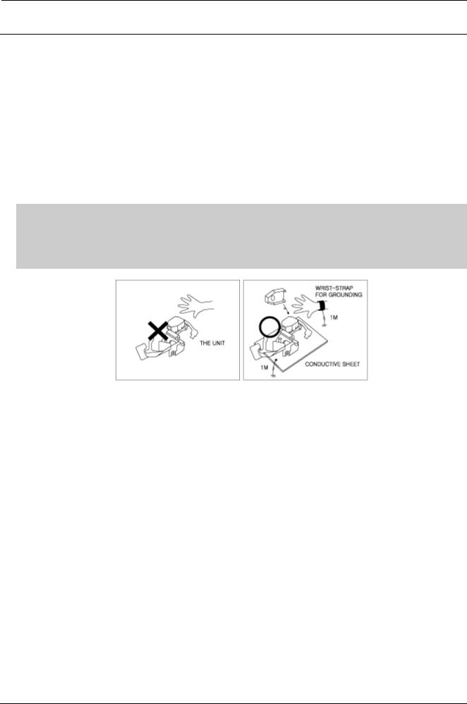
1.4. Handling the optical pick-up
The laser diode in the optical pick up may suffer electrostatic breakdown because of potential static electricity from clothing and your body.
The following method is recommended.
1)Place a conductive sheet on the work bench (The black sheet used for wrapping repair parts.)
2)Place the set on the conductive sheet so that the chassis is grounded to the sheet.
3)Place your hands on the conductive sheet(This gives them the same ground as the sheet.)
4)Remove the optical pick up block
5)Perform work on top of the conductive sheet. Be careful to let your clothes or any other static sources touch the unit.
 NOTE
NOTE
•Be sure to put on a wrist strap grounded to the sheet.
•Be sure to lay a conductive sheet, that is grounded to the table, made of copper.
Fig.1-3
6)Short the short terminal on the PCB, which is inside the Pick-Up ASS’Y, before replacing the PickUp. (The short terminal is shorted when the PickUp Ass’y is being lifted or moved.)
7)After replacing the Pick-up, open the short terminal on the PCB.
1-5 |
Copyright© 1995-2011 SAMSUNG. All rights reserved. |
2. Product Specifications
2. Product Specifications
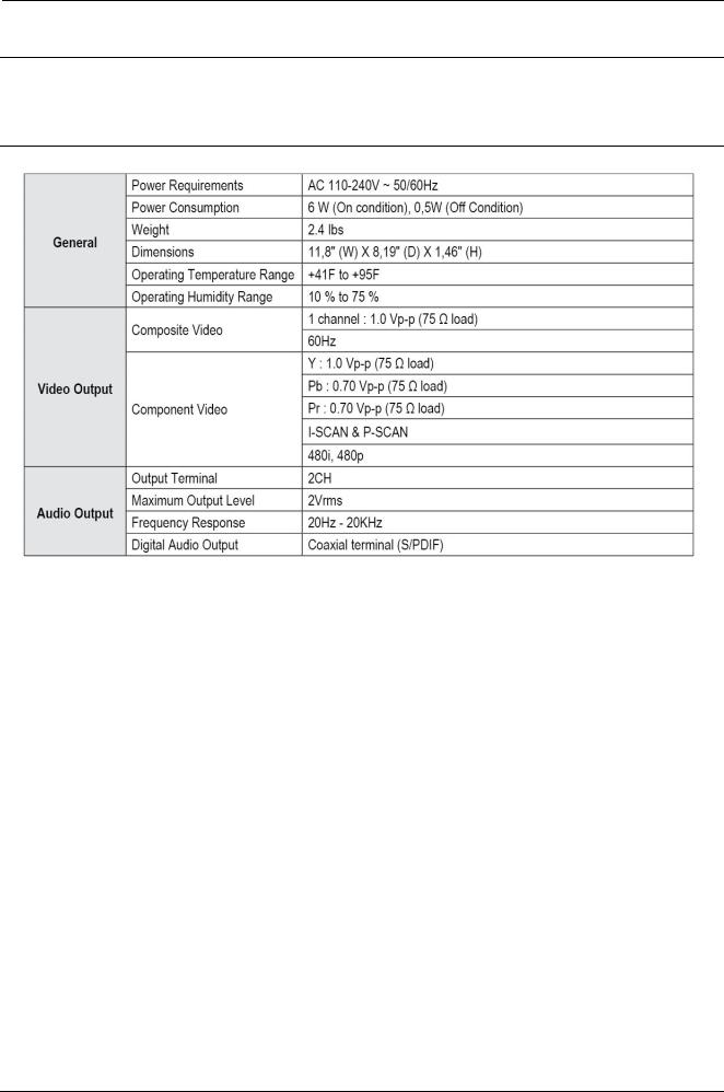
2.1. Product Specification
Copyright© 1995-2011 SAMSUNG. All rights reserved. |
2-1 |

2. Product Specifications
2.1.1. DVD General Features
•Digital Photo Viewer (JPEG)
You can view Digital Photos on your TV.
•MP3/WMA
This unit can play discs created from MP3/WMA files.
•Parental Control (DVD)
The parental control feature allows users to set the rating level of their player. This will prevent children from viewing harmful content such as violence and adult subject matter.
•Various On-screen Menu Function
You can select various languange (Audio/Subtitles) and screen angles while enjoying movies.
•EZ View (DVD)
Easy View enables picture adjustment to match your TV’s screen size (16:9 or 4:3)
•Excellent Sound
Dolby Digital, a technology developed by Dolby Laboratories, provides crystal clear sound reproduction.
•Progressive Scan
Progressive Scanning creates an improved picture with double the scan lines of conventional interlaced picture.
•CD RIPPING
This feature lest you to copy audio files from disc to USB device into MP3 format. (Only Audio CD (CDDA)).
•1080P PLAYBACK
This player upconverts regular DVD's to Full HD 1080p video.
2.1.2. Discs which cannot be played with this player
•DVD-R, +R
•CD-RW
•DVD+RW
•DVD-RW (V Mode)
•The unit may not play certain CD-R, CD-RW and DVD-R due to the disc type or recording condition.
2.1.3. Disc Type and Characteristics
The DVD Player is capable of playing the following types of discs with the corresponding logos :
2-2 |
Copyright© 1995-2011 SAMSUNG. All rights reserved. |
2. Product Specifications
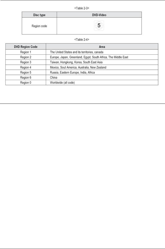
2.1.4. Region Code
The Region number for this DVD Player is described on the rear panel of the DVD Player.
Copyright© 1995-2011 SAMSUNG. All rights reserved. |
2-3 |
2. Product Specifications
2.1.5. USB
2-1-5 (a) Universal Serial Bus
Universal Serial Bus (USB) is a serial bus standart to interface devices.
•Designed to allow peripharels to be connected using a single standardized interface socket.
•Improve plug and play capabilities.
•Powering low comsumption devices without the need for external power supply.
•Allowing some devices to be used without requiring individual devices driver to be installed.
2-1-5 (b) Device Class
•0X08 : USB mass storage device class used for USB flash drives, Memory card reader, digital audio.
•0X09 : USB hubs
•0X0B : Smart card readers.
•0X0E : USB video device class, web cam like devices, motion image capture devices.
•0XE0 : Wireless controller, for example Bluetooth dongles.
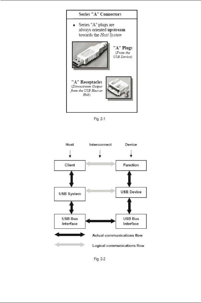
2-1-5 (c) USB Connector
•The connector are designed to be robust.
•It is difficult to incorrectly attach a USB connector.
•The connector are particularly cheap to manufacture.
•The connector enforce the directed topology of a USB network.
•Amoderate insertion / removal force is specified.
•The connector construction always ensures that the external sheaths on the plug contact with its counterpart in the receptacle before the four connector within are connected.
•The USB standart specifies relatively low tolerances for compliant USB connectors, intending to minimize incompatibilities in connectors produced by different vendor.
2-4 |
Copyright© 1995-2011 SAMSUNG. All rights reserved. |
2. Product Specifications
2-1-5 (d) Basic flow and interrelationship of the USB communication model.
Copyright© 1995-2011 SAMSUNG. All rights reserved. |
2-5 |

2. Product Specifications
2.2. Chassis Product Specification
2-6 |
Copyright© 1995-2011 SAMSUNG. All rights reserved. |
2. Product Specifications
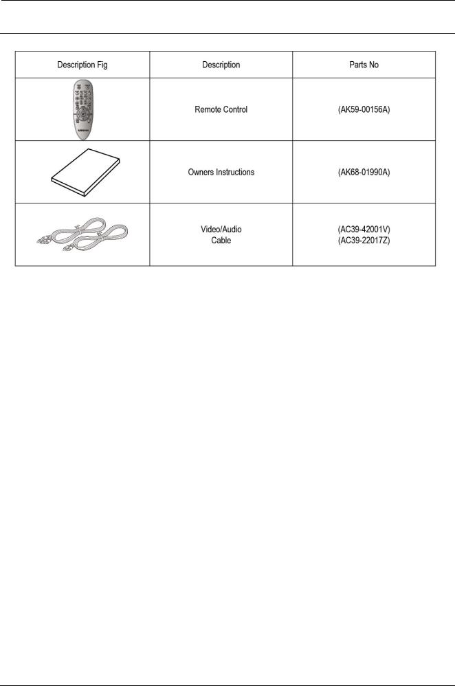
2.3. Option Product Specification
Copyright© 1995-2011 SAMSUNG. All rights reserved. |
2-7 |

3. Disassembly and Reassembly
3. Disassembly and Reassembly
3.1. Cabinet and PCB
 NOTE
NOTE
Connector Must be removed with care
3.1.1. Top Cabinet Removal
3-1 |
Copyright© 1995-2011 SAMSUNG. All rights reserved. |
3. Disassembly and Reassembly
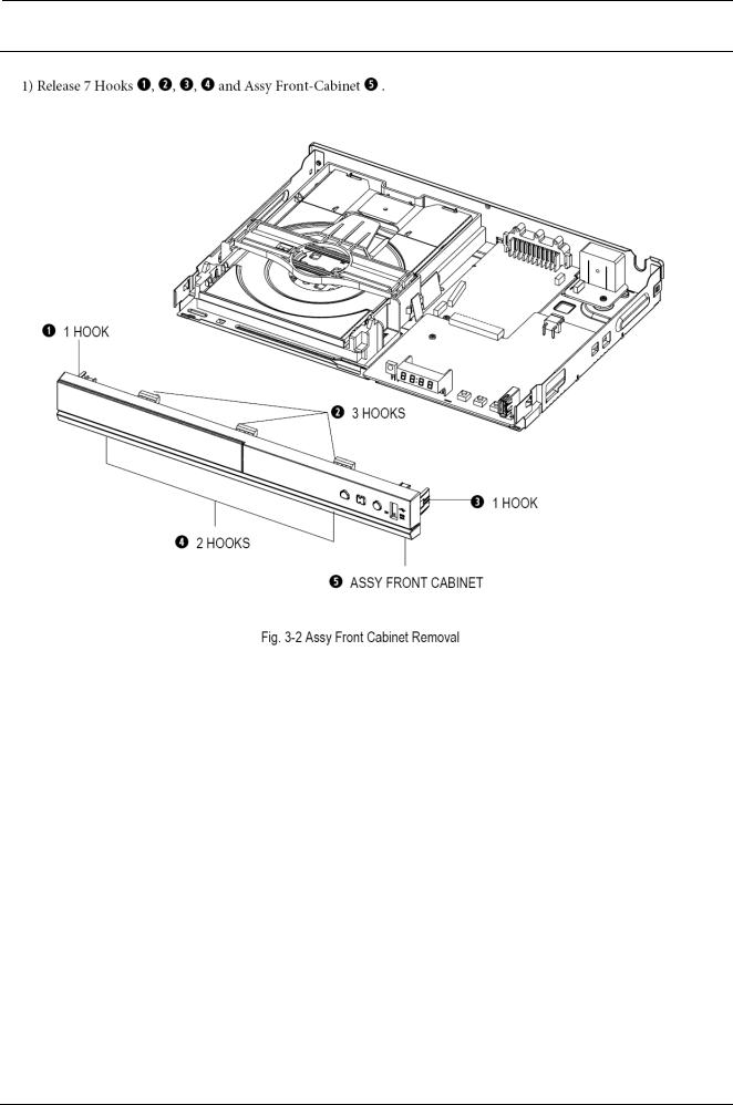
3.1.2. Assy Front Cabinet Removal
Copyright© 1995-2011 SAMSUNG. All rights reserved. |
3-2 |
3. Disassembly and Reassembly
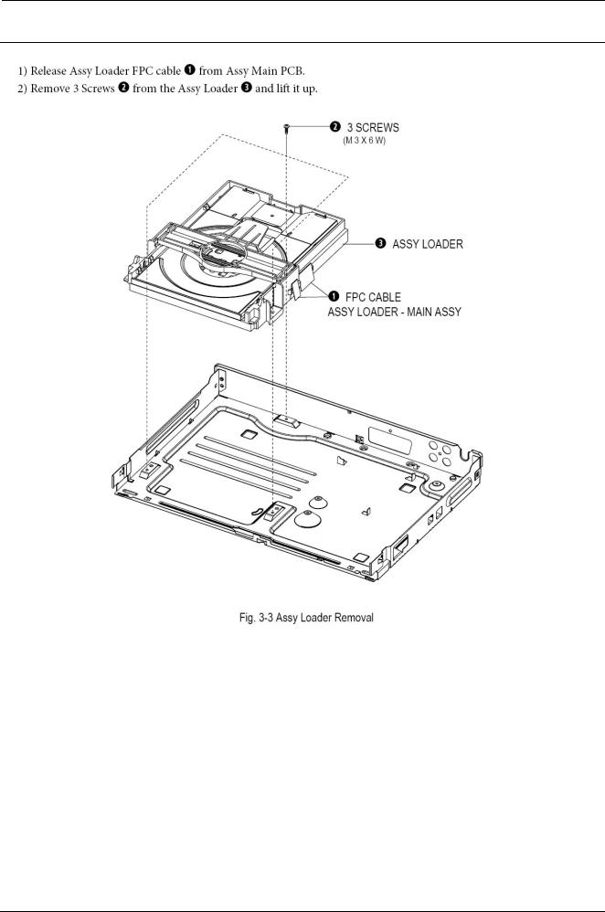
3.1.3. Assy Loader Removal
3-3 |
Copyright© 1995-2011 SAMSUNG. All rights reserved. |

3. Disassembly and Reassembly
3.1.4. Main PCB and S.M.P.S PCB and RCA Jack PCB Removal
Copyright© 1995-2011 SAMSUNG. All rights reserved. |
3-4 |
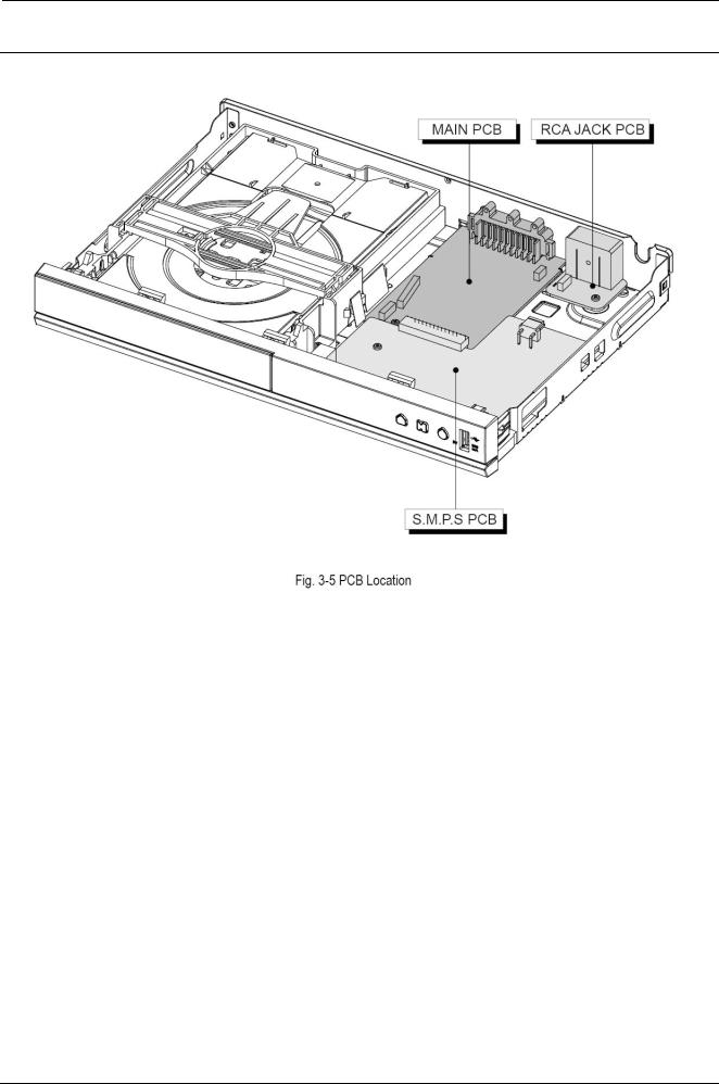
3. Disassembly and Reassembly
3.2. PCB Location
3-5 |
Copyright© 1995-2011 SAMSUNG. All rights reserved. |
4. Troubleshooting
4. Troubleshooting
4.1. Troubleshooting
Copyright© 1995-2011 SAMSUNG. All rights reserved. |
4-1 |
 Loading...