


ROOM AIR CONDITIONER
ASH-0906ER
ASH-1206ER
SERVICE Manual
AIR CONDITIONER |
CONTENTS |
1. Precautions
2. Product Specifications
3. Operating Instructions and
Installation
4. Disassembly and Reassembly
5. Troubleshooting
6. Exploded Views and Parts List
7. Block Diagrams
8. PCB Diagrams
9. Wiring Diagrams
10. Schematic Diagrams

1. Precautions |
|
|
|
|
1. Warning: Prior to repair, disconnect the |
d |
|
|
|
power cord from the circuit breaker. |
|
|
|
|
a |
ge |
|
||
|
n |
ro |
||
|
|
|
|
u |
|
|
|
|
s |
2. Use proper parts: Use only exact |
|
|
|
|
replacement parts. (Also, we recommend |
|
|
|
|
replacing parts rather than repairing them.) |
|
|
|
|
3. Use the proper tools: Use the proper tools |
|
|
|
|
and test equipment, and know how to use |
|
|
|
|
them. Using defective tools or test |
|
|
|
|
equipment may cause problems later- |
|
|
|
|
intermittent contact, for example. |
|
|
|
|
Fig. 1-1 |
Avoid Dangerous Contact |
|||
4.Power Cord: Prior to repair, check the power cord and replace it if necessary.
5.Avoid using an extension cord, and avoid tapping into a power cord. This practice may result in malfunction or fire.
6.After completing repairs and reassembly, check the insulation resistance. Procedure: Prior to applying power, measure the resistance between the power cord and the ground terminal. The resistance must be greater than 30 megohms.
7.Make sure that the grounds are adequate.
8.Make sure that the installation conditions are satisfactory. Relocate the unit if necessary.
9.Keep children away from the unit while it is being repaired.
10.Be sure to clean the unit and its surrounding area.
Fig. 1-2 No Tapping and No Extension Cords
Fig. 1-3 No Kids Nearby!
.K O
Fig. 1-4 Clean the Unit
Samsung Electronics |
1-1 |
M e m o
1-2 |
Samsung Electronics |

2. Product Specifications
2-1 Table
|
|
|
|
Model |
ASH-0906ER |
ASH-1206ER |
|||
Item |
|
|
|
|
Indoor unit |
outdoor unit |
Indoor unit |
|
outdoor unit |
Type |
|
|
|
- |
Wall-mounting |
Wall-mounting |
|||
|
Cooling |
|
|
BTU/h |
9,000 |
12,000 |
|||
|
Dehumiditying |
|
|
I/h |
1.7 |
1.7 |
|||
|
Heating |
|
|
BTU/h |
10,000 |
12,500 |
|||
|
Low temp. heating |
|
BTU/h |
|
- |
|
- |
||
Perfor- |
Air volume |
|
Cooling |
m3/min |
7.0 |
8.3 |
|||
|
|
Heating |
m3/min |
7.5 |
8.9 |
||||
mance |
|
|
|||||||
Noise |
|
Cooling |
dB |
40 |
51 |
40 |
|
51 |
|
|
|
|
|||||||
|
|
|
Heating |
dB |
40 |
51 |
40 |
|
51 |
|
Energy |
|
Cooling |
BTU/h.W |
10.0 |
10.0 |
|||
|
efficiency ratio |
Heating |
BTU/h.W |
9.8 |
9.7 |
||||
|
Power |
|
|
-V-Hz |
1-220/240-50 |
1-220/240-50 |
|||
|
Power |
|
Cooling |
W |
900 |
1,200 |
|||
Power |
consumption |
|
Heating |
W |
940 |
1,300 |
|||
Operating |
|
Cooling |
A |
4.0 |
5.0 |
||||
|
|
||||||||
|
current |
|
Heating |
A |
4.4 |
5.6 |
|||
|
Power |
|
Cooling |
% |
93.8 |
100 |
|||
|
factor |
|
Heating |
% |
89 |
96.7% |
|||
|
Starting current |
|
A |
20 |
25 |
||||
|
Power cord |
|
Length |
m |
2 |
- |
2 |
|
- |
|
|
|
Number of core wire |
250V 10/16A |
250V 10/16A |
||||
|
Fuse capacity |
|
|
A |
3.15 |
- |
3.15 |
|
- |
|
Outer |
|
Width x Height |
mm |
925x298x170 |
530x750x245 |
925x298x170 |
|
530x750x245 |
|
dimension |
|
x Depth |
inch |
36.43x11.73x6.69 |
20.87x29.53x9.65 |
36.43x11.73x6.69 |
|
20.87x29.53x9.65 |
|
Weight |
|
|
kg |
11.5 |
29 |
11.9 |
|
33 |
|
Refrigerant pipe |
Liquid |
OD(mm)x L(m) |
6.35 x 5 |
6.35 x 5 |
||||
Size |
|
|
GAS |
|
9.52x 5 |
12.7x 5 |
|||
Drain hose |
|
|
ID(mm) x L(mm) |
17x 2000 |
17x 2000 |
||||
|
|
|
|||||||
|
Compressor |
Type |
|
|
- |
Rotary |
- |
|
Rotary |
|
|
Motor |
Type |
|
- |
- |
- |
|
- |
|
|
|
Rated output |
W |
- |
- |
- |
|
- |
|
Blower |
Type |
|
|
Cross-fan |
Propeller |
Cross-fan |
|
Propeller |
|
|
Motor |
Type |
|
Resin |
Die casting |
Resin |
|
Die casting |
|
|
|
Rated output |
W |
35 |
20 |
35 |
|
20 |
Heat exchanger |
|
|
|
2Row 11Step |
1Row 28Step |
2Row 11Step |
|
1Row 28Step |
|
Refrigerant control unit |
|
|
|
|
- |
|
- |
||
Freezer oil capacity |
|
|
cc |
|
- |
|
- |
||
Refrigerant to change(R-22) |
|
g |
920 |
1000 |
|||||
Protection device |
|
|
|
|
MRA12037 |
|
|
MRA12030 |
|
|
|
|
|
|
- |
-12007 |
- |
|
-12008 |
|
|
|
|
|
|
|
|
|
|
∙Standard Conditions : ISO R5151 standards (indoor: 27 DB, 19 WB, outdoor: 35 DB, 24 WB)
Samsung Electronics |
2-1 |

2-2 Dimensions
2-2-1 Indoor Unit
(Front view) |
Remote control |
|
( ) |
Air in
298 |
190 |
925 |
170 |
63 |
|
|
21
Air out
Installation plate
( )
(Rear view)
142 |
|
|
37 |
123.5 |
123.5 |
|
228.5 |
258.5 |
2-2-2 Outdoor Unit |
|
|
245 |
|
|
(Front view) |
(Rear view) |
|
750 |
|
|
418.5 |
|
|
245 |
|
|
530 |
|
|
2-2 |
|
Samsung Electronics |

3. Operating Instructions and Installation
3-1 Operating Instructions
3-1-1 Name & Function of Key in remote controller
NO |
NAMED OF KEY |
|
|
|
|
|
FUNCTION OF KEY |
|
||||||||||||||||||
|
|
|
|
|
||||||||||||||||||||||
1 |
ON/OFF |
Use this button to start and stop air conditioner. |
ONE SHOT KEY |
|||||||||||||||||||||||
|
|
|
|
|
|
|
|
|
|
|||||||||||||||||
2 |
MODE |
Each time you press this button, |
|
|
|
|
|
ONE SHOT KEY |
||||||||||||||||||
|
|
|
MODE is changed in the following order. |
OR |
||||||||||||||||||||||
|
|
|
"AUTO"→ "COOL"→ "DRY"→ "FAN"→ "HEAT" |
|
|
|
CONTINUOUS KEY |
|||||||||||||||||||
|
|
|
|
|
|
|||||||||||||||||||||
|
|
|
|
|
|
|
|
|
|
|
|
|
|
|
|
|
|
|
|
|
|
|
|
|
|
|
|
|
|
|
|
||||||||||||||||||||||
3 |
TURBO |
Use this button to provide heavy duty cooling(heat) |
ONE SHOT KEY |
|||||||||||||||||||||||
|
|
|
for 30 minutes. |
|
|
|
|
|
|
|||||||||||||||||
4 |
MILD |
Use this button to provide pleasant cooling(heat) |
ONE SHOT KEY |
|||||||||||||||||||||||
|
|
|
for 3 hours. |
|
|
|
|
|
|
|||||||||||||||||
|
|
|
|
|
||||||||||||||||||||||
5 |
Q. TIMER |
Set up the reserve or cancel the timer on and timer off quickly |
ONE SHOT KEY |
|||||||||||||||||||||||
|
|
|
|
|
|
|
|
|
|
|
|
|
|
|
|
|
|
|
|
|
|
|
|
|
|
OR |
|
|
|
|
|
|
|
|
|
|
|
|
|
|
|
|
|
|
|
|
|
|
|
|
|
|
CONTINUOUS KEY |
6 |
FAN SPEED |
Each time you press this button, |
|
|
|
|
|
ONE SHOT KEY |
||||||||||||||||||
|
|
|
FAN SPEED is changed in the following order. |
OR |
||||||||||||||||||||||
|
|
|
"AUTO"→ " |
|
|
|
(L)" → " |
|
|
|
|
|
(ME)"→ " |
|
|
|
|
|
|
|
(HI)"→ NATURAL |
CONTINUOUS KEY |
||||
|
|
|
|
|
|
|
|
|
|
|
|
|||||||||||||||
|
|
|
|
|
|
|
|
|
|
|
|
|||||||||||||||
|
|
|
|
|
|
|
|
|
|
|
|
|
|
|
|
|
|
|
|
|
|
|
|
|
|
|
|
|
|
|
|
|
|
|
|
|
|
|
|
|
|
|
|
|
|
|
|
|
|
|
|
|
|
7 |
|
SET |
Adjusts air flow vertically. |
|
|
|
|
|
ONE SHOT KEY |
|||||||||||||||||
|
|
|
Each time you press this button, |
|
|
|
|
|
OR |
|||||||||||||||||
|
SWING |
|
BLADE-H rotates by 11 (Changable range 70 ) |
CONTINUOUS KEY |
||||||||||||||||||||||
|
|
|
|
|
|
|
|
|
|
|||||||||||||||||
|
|
AUTO |
Each time you press this button, |
|
|
|
|
|
ONE SHOT KEY |
|||||||||||||||||
|
|
|
BLADE-H rotates within 35 and stop. |
|
|
|
|
|
|
|||||||||||||||||
|
|
|
|
|
|
|
|
|
|
|
|
|
|
|
|
|
|
|
|
|
|
|
|
|
|
|
8 |
TIME |
Without regard to ON/OFF condition in remote controller, use |
ONE SHOT KEY |
|||||||||||||||||||||||
|
|
|
this button to set current time. |
|
|
|
|
|
|
|||||||||||||||||
|
|
|
Adjust the current time using ▲ TIME |
|
▼ button. |
|
||||||||||||||||||||
|
|
|
(Data can be transmitted after setting up the time) |
|
||||||||||||||||||||||
9 |
TIMER/CANCEL |
Use this button to reserve or cancel the timer on and timer off. |
ONE SHOT KEY |
|||||||||||||||||||||||
|
|
|
|
|
|
|
|
|
|
|
|
|
|
|
|
|
|
|
|
|
|
|
|
|
|
|
10 |
TIMER |
ON |
Set up the time that operation start. |
|
|
|
|
|
ONE SHOT KEY |
|||||||||||||||||
|
|
|
|
|
|
|
|
|
|
|
|
|
|
|
|
|
|
|
|
|
|
|
|
|
|
|
|
OFF |
Set up the time that operation stop. |
|
|
|
|
|
ONE SHOT KEY |
||||||||||||||||||
|
|
|
|
|
|
|
||||||||||||||||||||
|
|
|
|
|
||||||||||||||||||||||
11 |
|
|
If the ▲ TIME button is pressed once, the time increase by one |
ONE SHOT KEY |
||||||||||||||||||||||
|
|
▲ (UP) |
minute during the time set mode, and ten minutes during the timer |
OR |
||||||||||||||||||||||
|
TIME |
|
set mode. |
|
|
|
|
|
CONTINUOUS KEY |
|||||||||||||||||
|
|
|
|
|
|
|
|
|
|
|
|
|
|
|
|
|
|
|
|
|
|
|
|
|
|
|
|
|
If the TIME ▼ button is pressed once, the time decrease by one |
ONE SHOT KEY |
|||||||||||||||||||||||
|
|
|
||||||||||||||||||||||||
|
|
▼ (DOWN) |
minute during the time set mode, and ten minutes during the |
OR |
||||||||||||||||||||||
|
|
|
timer set mode. |
|
|
|
|
|
CONTINUOUS KEY |
|||||||||||||||||
|
|
|
|
|
|
|
|
|
|
|||||||||||||||||
12 |
|
▲ (UP) |
If the ▲ button is pressed once, |
|
|
|
|
|
|
|||||||||||||||||
|
TEMP |
|
the setting temperature is increased by 1 |
ONE SHOT KEY |
||||||||||||||||||||||
|
▼ (DOWN) |
If the ▼ button is pressed once, |
|
|
|
|
|
OR |
||||||||||||||||||
|
|
|
|
|
|
|
CONTINUOUS KEY |
|||||||||||||||||||
|
|
|
the setting temperature is decreased by 1 |
|
||||||||||||||||||||||
|
|
|
|
|
|
|
|
|
|
|
|
|
|
|
|
|
|
|
|
|
|
|
|
|
|
|
13 |
SLEEP |
Use this button for sleep operation. |
|
|
|
|
|
ONE SHOT KEY |
||||||||||||||||||
|
|
|
(The SLEEP mode can be selected at COOL and HEAT mode.) |
|||||||||||||||||||||||
|
|
|
|
|||||||||||||||||||||||
|
|
|
|
|
|
|
|
|
|
|
|
|
|
|
|
|
|
|
|
|
|
|
|
|
|
|
Samsung Electronics |
3-1 |

Operating Instructions and Installation
3-1-2 Main controller function.
1.AUTO MODE : In this mode, operation mode(COOL, HEAT, DRY) is selected automatically by the room temperature of initial operation.
Room Temp |
Operation Type |
Tr≥ 21 + T Cool Operation (Set Temp:AUTO SETTING)
21 + T Tr Heat Operation (Set Temp : 22 + T)
T= -1 , -2 , 0 +1 +2
T is controlled by setting temperature up/down key of remote controller
2.COOL MODE : The unit operates according to the difference between the setting and room temperature.
The setting temperature is compensated by the room humidity. (18 ~30 )
3.HEAT MODE : The unit operates according to the difference between the setting and room temperature.
The setting temperature is not compensated by the room humidity. (16 ~30 )Prevention against cold wind : For about 3~5 minutes after initial operation, thermo
control or de-ice , the indoor fan will either not operate or operate very slowly(650 rpm), then switch to the selected fan speed. This period is to allow the indoor unit's heatexchanger to prewarm before emitting warm air.
Protective function : High temperature release.
De-ice : Deicing operation is controlled by indoor unit's heat exchanger temperature and room temperature and accumulating time of compressor's operation.
4.DRY MODE : Has 4 states, each determined by room temperature and humidity.
When the room temperature is below the setting temperature and the room relative humidity below 60% RH, the unit operates in FAN mode.
compressor ON/OFF Time is controlled compulsorily(can not set up the fan speed, always breeze).
Protective function : Low temperature release. (Prevention against freeze)
5.TURBO MODE : This mode is available only in AUTO, COOL, HEAT mode.
When this button is pressed at first, the air
conditioner is operated powerful state for 30 minutes regardless of the set temperature, room temperature and humidity.
When this button is pressed again, or when the operating time is 30 minutes, turbo operation mode is canceled and returned to the previous mode.
6.MILD MODE : This mode is available only in AUTO, COOL, HEAT mode
When this button is pressed at first, the air conditioner is operated in its current state for 3 hours.
When this button is pressed again or when the operating time is 3 hours, mild operation mode is canceled and returned to the previous mode.
7.SLEEP MODE : Sleep mode is available only in COOL or HEAT mode.
The operation will stop after 6 hours.
In COOL mode : The setting temperature is automatically raised by 1 each 1hour When the temperature has been raised by total of 2 , that temperature is maintained.In HEAT mode : The setting temperature is automatically droped by 1 each 1hour. When the temperature has been droped by total of 2 , that temperature is maintained.
3-2 |
Samsung Electronics |

Operating Instructions and Installation
8.DE-ICE Operation : De-ice operation is controlled by sensing the indoor unit's heatexchanger temperature and timer.
De-ice ends by sensing of the processing time by de-ice condition.
9.FAN SPEED : Manual (3 step), Auto (5 step), Natural
Fan speed automatically varies depending on both the difference between setting and the room temperature and room humidity.
10.COMPULSORY OPERATION :
For operating the air conditioner without the remote controller.
AUTO : The operating is the same function that AUTO MODE in the remote controller.
11.SWING : BLADE-H is rotated vertically by the stepping motor.
Memory louver : When ON/OFF button is pressed at stop state, the BLADE-H returns to its original location which is operating state before stop
Swing auto : The BLADE-H can rotate within about 15 in the original position set by the SWING SET button.
Swing set : Press the SWING SET button, then the blade rotates vertically by 11 The BLADE-H location is dispalyed on REMOTE CONTROL. (total 7 steps)
12.Q.TIMER: Q. timer(quick timer) allows reservation or cancel the timer on and timer off quickly
When Q.timer button is pressed at operating state, LCD displays the polling state sequentially.
The LCD also displays the time remaining.
13.TIMER : The air conditioner is turned ON/OFF at a specified time using TIMER ON/OFF.
ON TIMER : Only timer LED lights on.OFF TIMER : Both timer and operation LED lights on.
3 minutes delay timer.
14.SELF TEST
Interruption of electric power and Power on.
Abnormal condition of the room sensor.Indoor unit fan motor lock.Abnormal condition of the indoor unit's heat exchanger sensor.
15.TIME SHORTENING : If the "Time short" connector pin is shorted on the main P. C. B, the compressor's three minutes delay function is cancelled, and each operation time is shortened to one fiftieth of its original time.
16.BUZZER SOUND : Whenever the ON/OFF button is pressed or whenever change occurs to the condition which is set up or select, the compulsory operation mode, buzzer is sounded "beep"
Samsung Electronics |
3-3 |

3-2 Installation
3-2-1 Selecting Area for Installation
Select an area for installation that is suitable to the customer's needs.
3-2-1(a) Indoor Unit
1.Make sure that you install the indoor unit in an area providing good ventilation. It must not be blocked by an obstacle affecting the airflow near the air inlet and the air outlet.
2.Make sure that you install the indoor unit in an area allowing good air handling and endurance of vibration of the indoor unit.
3.Make sure that you install the indoor unit in an area where there is no source of heat or vapor nearby.
4.Make sure that you install the indoor unit in an area from which hot or cool air is spread evenly in a room.
5.Make sure that you install the indoor unit in an area away from TVs, audio units, cordless phones, fluorescent lighting fixtures and other electrical appliances (at least 1 meter).
6.Make sure that you install the indoor unit in an area which provides easy pipe connection with the outdoor unit, and easy drainage for condensed water.
7.Make sure that you install the indoor unit in an area which is large enough to accomodate the measurements shown in figure on the next page.
3-2-1(b) Outdoor Unit
1.Make sure that you install the outdoor unit in area not exposed to the rain or direct sun light.
(Install a separate sunblind if exposed to direct sun light.)
2.Make sure that you install the outdoor unit in area allowing good air moment, not amplifying noise or vibration, especially to
avoid disturbing neighbours.
(Fix the unit firmly if it is mounted in a high place.)
3.Make sure that you install the outdoor unit in area providing good ventilation and which is not dusty. It must not be blocked by any obstacle affecting the airflow near the air inlet and the air outlet.
4.Make sure that you install the outdoor unit in area free from animals or plants.
5.Make sure that you install the outdoor unit in area not blocking the traffic.
6.Make sure that you install the outdoor unit in area easy to drain condensed water from the indoor unit.
7.Make sure that you install the outdoor unit in area which provides easy connection within the maximum allowable length of a coolant pipe(15 meters).
Note
1.Add 10 grams of refrigerant(R-22) for every 1 meter if the pipe length exceeds the standard pipe length of 5 meters.
2.Maintain a height between the indoor and outdoor units of less than 3 meters.
8.Make sure that you install the outdoor unit in an area which is large enough to accommodate the measurements
shown in figure on the next page.
3-2-1(c) Remote Control Unit
1.Make sure that you install the remote control unit in an area free from obstacles such as curtains etc, which may block signals from the remote control unit.
2.Make sure that you install the remote control unit in an area not exposed to
direct sunlight, and where there is no source of heat.
3.Make sure that you install the remote control unit in an area away from TVs, audio units, cordless phones, fluorescent lighting fixtures and other electrical appliances (at least 1 meter).
Caution :
It is harmful to the air conditioner if it is used in the following environments: greasy areas(including areas near machines), salty areas such as coast areas, areas where sulfuric gas is present such as hot spring areas. Contact your dealer for advice.
3-4 |
Samsung Electronics |
Operating Instructions and Installation
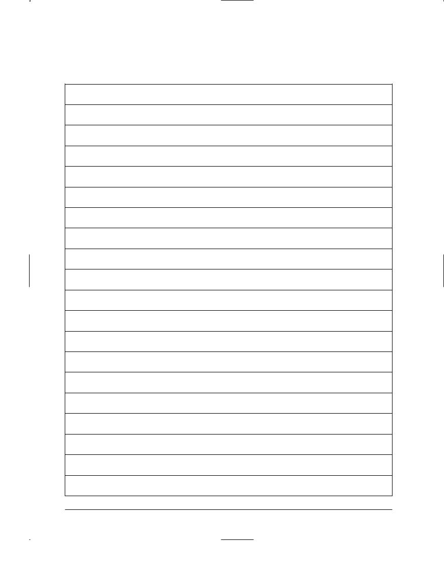
3-2-2 Installation diagram of indoor unit and outdoor unit
A Indoor unit gas leak test check point
Indoor
unit
Tape Vinyl
Piping
B Drain hose installation
Cut the piping hole sloped slightly
Piping may be laid to the rear, left, right or down .
Right |
|
Left |
Rear |
Down |
Rear |
|
|
|
|
70mm or more |
|
450mm or more |
400mm or more |
A
B
 Remote control Remote control holder
600mm minimum
10 |
0m |
|
|
|
m |
|
m |
|
in |
|
im |
|
um |
|
minimum |
|
600mm |
|
Piping (Liquid) 1/4" |
|
Clamper tube |
|
Piping (Gas) 1/2" |
|
Installation plate |
|
Installation tube |
|
Pipe-connection |
|
Vinyl tape |
|
Screw |
|
Putty |
|
Drain hose |
|
|
|
|
Samsung Electronics |
3-5 |
Operating Instructions and Installation
3-2-2(a) Cutting a hole and mounting installation plate
CUTTING A HOLE
 Installation plate
Pipe hole( 65mm)
142mm
37mm
Determine the pipe hole position using the paper pattern for installation and drill the pipe hole (65mm inner diameter) so that it slants slightly downward.
123.5mm
MOUNTING THE INSTALLATION PLATE
●When the installation plate is directly mounted on the wall.
|
|
70mm |
Anchor bolt |
|
|
|
|
|
400mm |
|
450mm |
|
|
|
20mm |
142mm |
|
Weight |
or less |
Pipe hole |
installation plate |
||
|
( 65mm) |
|
|
|
|
|
|
37mm |
123.5mm |
indoor unit |
123.5mm |
|
228.5mm |
258.5mm |
|
|
|
||
|
|
|
cutting part |
1.Separate the cutting part of the installation plate before installing the installation plate.
2.Install the installation plate horizontally on structural members (studs, etc) in the wall.
3.To mount the installation plate on a concrete wall with anchor bolts, utilize the anchor bolt holes as illustrated in the left figure.
4.When the anchor bolts are already driven in the wall, also utilize the anchor bolts holes to secure the installation plate.(If an anchor bolt is too long, adjust the projecting length to 20mm or less.)
● Mounting at the window frame
Screw wood |
Wood pillar |
3-2-2(b) Wiring connection (indoor unit)
Screw
1. When mounting installation-plate at the window frame.
Use the paper patten for installation of the wood pillar.
¡›
2. As the left Fig.
410 730mm |
Fix the wood pillar at the wood frame |
|
|
|
and install installation-plate with |
|
screw-tap. |
3.Fix the wood pillar with enough strength to bear the weight of the indoor unit.
1.Open the Grille and remove the screw securing the cover.
2.Firmly connect the cable connector with ELconnector. (3pin)
3.Assembly every parts by contrary order to disassembly.
3-6 |
Samsung Electronics |
Operating Instructions and Installation
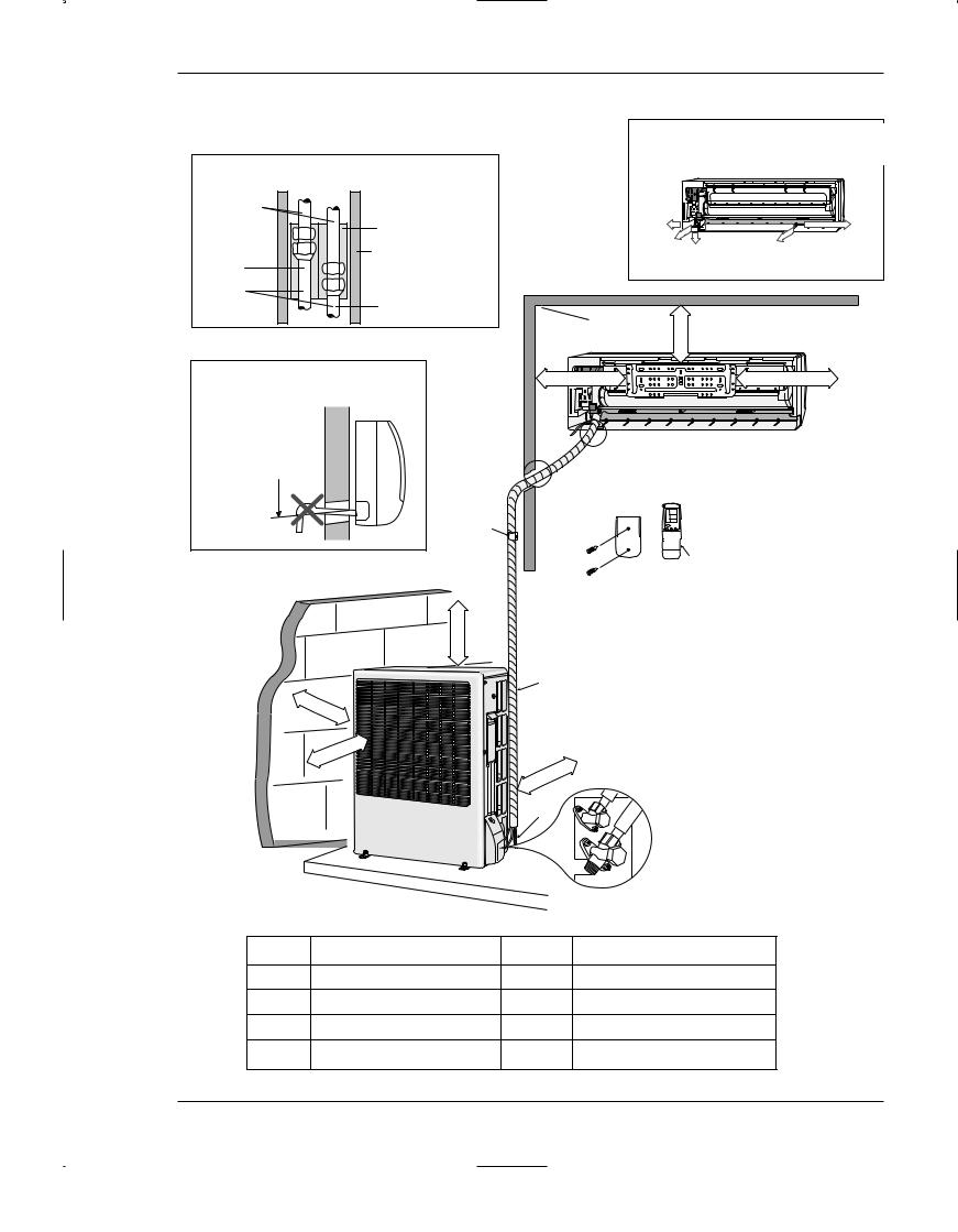
3-2-2(c) Piping and drain hose installation
1.Fix the drain hose under the refrigerant piping.
2.Be careful not to allow slack of the drain hose.
3.Do not allow the piping to jut out from the back of the indoor unit.
4.Insulate both of the refrigerant pipes so that dewing and other problems do not occur.
5.Be careful in bending the pipes. The bending radius must be 100mm or larger.
Right-hand connection with piping |
Left-hand connection with piping |
Piping |
Tape |
Assembly cable |
Drain hose |
|
Under-side connection with piping
|
|
Bush-Body |
|
|
of the rear body |
|
|
Assembly |
|
|
piping |
|
|
Holder pipe |
|
|
1. Open the rear left Bush-Body.
1. |
Open the rear right Bush- |
|
|
1. Cut out the knock-out piece from the |
|
|
under side of the rear body with a |
||
|
Body. |
|
knife, etc. Smooth the cut edges. |
|
|
|
|
||
2. |
Cut out the Holder-pipe slit |
|
|
2. Cut out the holder pipe on its slit part. |
|
part. |
|
Piping |
|
3. |
Support the above section to |
|
|
|
|
be bent with your hand and |
|
|
|
|
bend the pipes there. |
|
|
|
|
|
Installation |
|
Set the drain hose in the inner part of the |
|
|
Drain hose |
indoor unit and the assembly cable in |
|
|
|
plate |
lower part of it. Wind tape round them. |
|
|
|
|
Assembly Cable |
|
|
|
|
|
3-2-2(d) Indoor unit
Hook here
2
DRAINAGE
1.Run the drain hose sloped downward.
2.Do not install the drain hose as illustrated below.
3
1
5cm less
Ditch
3. Put water in the drain pan and make sure that the water is drained outdoor.
4. When connecting extension drain hose. insulate the inside part of extension drain hose with shield.
Shield
 Pipe holder plate
Drain hose |
Extension drain hose |
1.To fix the pipe of the indoor unit with the fixing screw, utilize the pipe holder plate as illustrated in the figure.
2.Pass the pipes through the hole in the wall, and hook the indoor unit to the installation plate.
3.Move the indoor unit to the right and left to make sure that the unit is securely hooked on to the installation plate.
Samsung Electronics |
3-7 |

Operating Instructions and Installation
3-2-2(e) Outdoor unit installation
Wiring connection
1.Remove the cover-valve.
2.Firmly connect the cable connector with EL-connector. (4. pin)
3.Fasten the M4 ring terminal to the hole marked
4.Firmly fix the ass'y cable with clamp wire holder.
5.Assemble the cover-valve.
6.To prevent the entry of water, form a trap of the ass'y cable as illustrated in the installation diagram of indoor and outdoor unit.
EL Connector
Screw |
Clamp Wire Holder |
|
|
Grounding Screw Hole |
|
Installation of drain line
In heating and de-ice operation, condensed water may be generated. Install drain line as following procedure.
1.Insert drain plug into hole and then connect drain hose to drain plug. *Inside diameter of drain hose is 18mm
Drain hole
 Drain plug
Grounding
(The parts for this work are optional)
●The grounding screw hole is located in the position shown.
●A grounding terminal can be found on the outdoor unit as illustrated.
Grounding screw hole
3-8 |
Samsung Electronics |
Operating Instructions and Installation
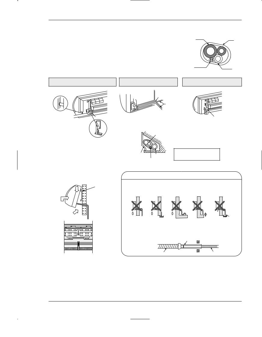
3-2-2(f) Flare Modification
● Tools used
Flare modification procedure
1)Cut the pipe using a pipe cutter.
90 |
Slanted Rough |
2) Remove burrs at the tip of the pipe cut.
Caution : Burrs not removed may result in leakage of gas.
Pipe
Reamer
3)Insert a flare nut into the pipe and modifty flare.
D
A
Outer diameter |
A(mm) |
6.35mm 1.3
9.52mm 1.8
12.7mm 2.0
* Unproper flaring
Inclined |
Surface |
Cracked |
Uneven |
|
damaged |
|
thickness |
Samsung Electronics |
3-9 |
Operating Instructions and Installation
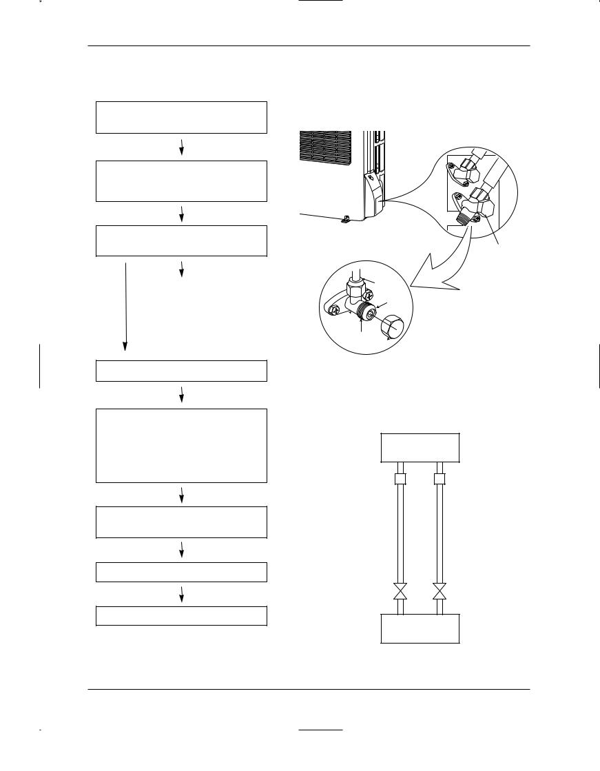
3-2-2(g) Air-Purge Procedure
Use the refrigerant of the outdoor unit to purge air inside indoor unit and pipe.
1. Remove the caps from the 2-way valve(B) and the 3-way valve(A).
2-Way Valve
2 Turn the 2-way valve cock approx. 45° counterclockwise to open it. Close it about 10 seconds later.
3Check refrigerant leakage of each joint parts (A, B, C & D in right figure)
|
|
|
Ieaking |
|
|
|
|
|
|
|
|
Leaking |
||
|
|
|
||
|
|
If leaking, tighten the flare nut one more time. |
||
not |
||||
leaking |
|
If continues to leak, although the pipe fixing |
||
|
|
area has been tightened again, |
||
|
|
|||
|
|
repair the leaking area. |
||
|
|
|
|
|
4.Open the 2-way valve again.
5.Open the service valve cap of the 3-way valve and press the needle valve to discharge gas for 3 seconds and leave it for about 1 minute.
Repeat the above procedure for 3 times to purge air.
6.Open the 2-way valve and 3-way valve completely
7.Close the cap of each valve.
3-Way Valve
Flare nut
Stopper
Valve
body Valve Stem
Valve Stem cap
|
Indoor Unit |
|
Half union |
D |
C |
|
|
Liquid pipe side |
Gas pipe side |
2-way valve |
3-way valve |
B |
A |
8. Check each valve for leakage.
Outdoor Unit
3-10 |
Samsung Electronics |

Operating Instructions and Installation
3-2-2(h) Refrigerant Refill
●Refill an air-conditioner with refrigerant when refrigerant has been leaked at installing or using
1.Purge air(for new installation only).
2.Turn the 3-way valve clockwise to close, connect the pressure gauge(low pressure side) to the service valve, and open the 3-way valve again.
3.Connect the tank to refill with Refrigerant
4.Set the unit to cool operation mode.
←Suspension hook
5.Check the pressure indicated by the pressure gauge(low pressure side).
*Standard pressure is should be 4.5~5.5kg/cm2 in a reqular, high operation mode.
6.Open the refrigerant tank and fill with refrigerant until the rated pressure is reached.
*It is recommended not to pour the refrigerant in too quickly, but gradually while operating a pressure valve.
Compound  gauge
gauge


|
|
High pressure gauge
Handwheel
←Finger tight fittings
|
Connected to |
For mounting |
|
other and of |
high pressure |
hose when |
side |
not in use
Charging line
2Way-WayValve
R-22
7. Stop operation of the air conditioner.
|
|
|
|
|
|
|
|
|
|
8. Close the 3-way valve, disconnect the |
|
3Way- |
Valve |
|
|
|
|
||
pressure gauge, and open the 3-way |
|
|
|
|
|
|
|
||
valve again. |
|
|
|
|
|
|
|
|
|
|
|
|
|
|
|
|
|
|
|
9. Close the cap of each valve.
Samsung Electronics |
3-11 |

Operating Instructions and Installation
3-2-2(i) Refrigerant Adjustment
Class |
At |
installation |
At |
service |
||
|
|
|
|
|
|
|
Connection |
Air-Purge |
|
Refrigerant |
Air-Purge |
|
Refrigerant |
Pipe Length |
Method |
|
Adjustment |
Method |
|
Quantity |
|
|
|
|
|
|
|
|
Refer to the |
|
Unnecessary |
|
|
refer to |
5m Max. |
detailed Air-Purge |
|
|
Purge air using a |
|
specification sheet |
|
Procedure |
|
|
vaccum pump |
|
|
|
|
|
|
or an additional |
|
|
|
|
|
|
|
|
|
|
|
|
Add 10g of refrigerant |
refrigerant cylinder. |
|
Add 10g of refrigerant |
5~10m |
|
|
(R-22) for every 1m. |
|
|
(R-22) for every 1m. |
|
|
|
|
|
|
|
3-2-2(j) Flare unt fixing torque
|
Outter diameter |
Torque |
(kg-cm) |
|
|
|
|
|
|
|
|
Fixing Torque |
|
Final Torque |
|
|
|
|
|
6.35 |
(9000Btu, 12000Btu) |
160 |
|
200 |
(Liquid Side) |
|
|||
|
|
|
||
|
|
|
|
|
9.52 |
(9000Btu) |
300 |
|
350 |
(Gas Side) |
|
|||
|
|
|
||
|
|
|
|
|
12.7 |
(12000Btu) |
500 |
|
550 |
(Gas Side) |
|
|||
|
|
|
||
|
|
|
|
|
3-12 |
Samsung Electronics |
 Loading...