

Page 1
Installation Instructions
MicroLogix 1400 Programmable Controllers
Catalog Number(s) 1766-L32AWA, 1766-L32AWAA,
1766-L32BWA, 1766-L32BWAA, 1766-L32BXB,
1766-L32BXBA
http://literature.rockwellautomation.com/idc/groups/literature/documents/in/1
766-in001_-mu-p.pdf
FR
Cette publication est disponible en français sous forme électronique (fichier PDF). Pour la
télécharger, rendez-vous sur la page Internet indiquée ci-dessus.
IT
DE
ES
PT
Questa pubblicazione è disponibile in Italiano in formato PDF. Per scaricarla collegarsi al sito
Web indicato sopra.
Diese Publikation ist als PDF auf Deutsch verfügbar. Gehen Sie auf die oben genannte
Web-Adresse, um nach der Publikation zu suchen und sie herunterzuladen.
Esta publicación está disponible en español como PDF. Diríjase a la dirección web indicada
arriba para buscar y descarga esta publicación.
Esta publicação está disponível em portugués como PDF. Vá ao endereço web que aparece
acima para encontrar e fazer download da publicação.
Page 2

Page 3
Installation Instructions
MicroLogix 1400 Programmable Controllers
Catalog Number(s) 1766-L32AWA, 1766-L32AWAA,
1766-L32BWA, 1766-L32BWAA, 1766-L32BXB,
1766-L32BXBA
Topic Page
Important User Information 4
Additional Resources 7
Overview 8
Controller Description 9
Hazardous Location Considerations 11
Mount the Controller 13
Connect 1762 I/O Expansion Modules 18
Wire the Controller 19
Specifications 28
Page 4
4 MicroLogix 1400 Programmable Controllers
Important User Information
Solid state equipment has operational characteristics differing from those of electromechanical equipment.
Safety Guidelines for the Application, Installation and Maintenance of Solid State Controls (Publication
SGI-1.1 available from your local Rockwell Automation sales office or online at
http://literature.rockwellautomation.com
equipment and hard-wired electromechanical devices. Because of this difference, and also because of the
wide variety of uses for solid state equipment, all persons responsible for applying this equipment must
satisfy themselves that each intended application of this equipment is acceptable.
In no event will Rockwell Automation, Inc. be responsible or liable for indirect or consequential damages
resulting from the use or application of this equipment.
The examples and diagrams in this manual are included solely for illustrative purposes. Because of the many
variables and requirements associated with any particular installation, Rockwell Automation, Inc. cannot
assume responsibility or liability for actual use based on the examples and diagrams.
No patent liability is assumed by Rockwell Automation, Inc. with respect to use of information, circuits,
equipment, or software described in this manual.
Reproduction of the contents of this manual, in whole or in part, without written permission of Rockwell
Automation, Inc., is prohibited.
Throughout this manual, when necessary, we use notes to make you aware of safety considerations.
) describes some important differences between solid state
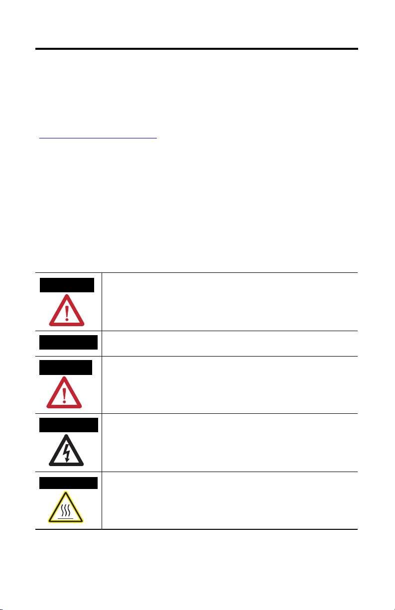
WARNING
IMPORTANT
ATTENTION
SHOCK HAZARD
BURN HAZARD
Identifies information about practices or circumstances that can cause an explosion in
a hazardous environment, which may lead to personal injury or death, property
damage, or economic loss.
Identifies information that is critical for successful application and understanding of
the product.
Identifies information about practices or circumstances that can lead to personal injury
or death, property damage, or economic loss. Attentions help you identify a hazard,
avoid a hazard and recognize the consequences.
Labels may be on or inside the equipment (for example, drive or motor) to alert people
that dangerous voltage may be present.
Labels may be on or inside the equipment (for example, drive or motor) to alert people
that surfaces may reach dangerous temperatures.
Publication 1766-IN001C-EN-P - October 2009
Page 5
Environment and Enclosure
MicroLogix 1400 Programmable Controllers 5
ATTENTION
This equipment is intended for use in a Pollution Degree 2 industrial
environment, in overvoltage Category II applications (as defined in IEC
publication 60664-1), at altitudes up to 2000 meters (6562 ft) without derating.
This equipment is considered Group 1, Class A industrial equipment according to
IEC/CISPR Publication 11. Without appropriate precautions, there may be
potential difficulties ensuring electromagnetic compatibility in other
environments due to conducted as well as radiated disturbance.
This equipment is supplied as open-type equipment. It must be mounted within
an enclosure that is suitably designed for those specific environmental
conditions that will be present and appropriately designed to prevent personal
injury resulting from accessibility to live parts. The enclosure must have suitable
flame-retardant properties to prevent or minimize the spread of flame,
complying with a flame spread rating of 5VA, V2, V1, V0 (or equivalent) if
non-metallic. The interior of the enclosure must be accessible only by the use of
a tool. Subsequent sections of this publication may contain additional
information regarding specific enclosure type ratings that are required to comply
with certain product safety certifications.
Preventing Electrostatic Discharge
ATTENTION
This equipment is sensitive to electrostatic discharge, which can cause internal
damage and affect normal operation. Follow these guidelines when you handle
this equipment:
• Touch a grounded object to discharge potential static.
• Wear an approved grounding wriststrap.
• Do not touch connectors or pins on component boards.
• Do not touch circuit components inside the equipment.
• Use a static-safe workstation, if available.
• Store the equipment in appropriate static-safe packaging when not in use.
Publication 1766-IN001C-EN-P - October 2009
Page 6
6 MicroLogix 1400 Programmable Controllers
North American Hazardous Location Approval
The following modules are North American Hazardous Location approved: 1766-L32AWA,
1766-L32AWAA, 1766-L32BWA, 1766-L32BWAA, 1766-L32BXB, 1766-L32BXBA
The following information applies when
operating this equipment in hazardous
locations:
Products marked "CL I, DIV 2, GP A, B, C, D" are
suitable for use in Class I Division 2 Groups A, B, C,
D, Hazardous Locations and nonhazardous locations
only. Each product is supplied with markings on the
rating nameplate indicating the hazardous location
temperature code. When combining products within
a system, the most adverse temperature code
(lowest "T" number) may be used to help determine
the overall temperature code of the system.
Combinations of equipment in your system are
subject to investigation by the local Authority Having
Jurisdiction at the time of installation.
WARNING
EXPLOSION HAZARD
•Do not disconnect while the
circuit is live or unless the area
is known to be free of ignitible
concentrations.
•Do not disconnect connections
to this equipment unless power
has been removed or the area is
known to be nonhazardous.
Secure any external connections
that mate to this equipment by
using screws, sliding latches,
threaded connectors, or other
means provided with this
product.
• Substitution of components may
impair suitability for Class I,
Division 2.
• Do not remove or replace lamps,
fuses or plug-in modules (as
applicable) unless power has
been disconnected or the area is
known to be free of ignitible
concentrations of flammable
gases or vapors.
Informations sur l’utilisation de cet
équipement en environnements
dangereux:
Les produits marqués "CL I, DIV 2, GP A, B, C, D" ne
conviennent qu’à une utilisation en environnements
de Classe I Division 2 Groupes A, B, C, D dangereux et
non dangereux. Chaque produit est livré avec des
marquages sur sa plaque d’identification qui
indiquent le code de température pour les
environnements dangereux. Lorsque plusieurs
produits sont combinés dans un système, le code de
température le plus défavorable (code de température
le plus faible) peut être utilisé pour déterminer le code
de température global du système. Les combinaisons
d’équipements dans le système sont sujettes à
inspection par les autorités locales qualifiées au
moment de l’installation.
AVERTISSEMENT
RISQUE D’EXPLOSION
•Couper le courant ou s’assurer
que l’environnement est classé
non dangereux avant de
débrancher l'équipement.
•Couper le courant ou s'assurer
que l’environnement est classé
non dangereux avant de
débrancher les connecteurs. Fixer
tous les connecteurs externes
reliés à cet équipement à l'aide
de vis, loquets coulissants,
connecteurs filetés ou autres
moyens fournis avec ce produit.
•La substitution de composants
peut rendre cet équipement
inadapté à une utilisation en
environnement de Classe I,
Division 2.
•S’assurer que l’environnement
est classé non dangereux avant
de changer les piles.
Publication 1766-IN001C-EN-P - October 2009
Page 7
MicroLogix 1400 Programmable Controllers 7
Additional Resources
Resource Description
MicroLogix 1400 Programmable Controllers User
Manual 1766-UM001
MicroLogix 1400 Instruction Set Reference
Manual 1766-RM001
Installation Instructions 1762-INxxx Information on installing and using 1762 expansion I/O
Industrial Automation Wiring and Grounding
Guidelines 1770-4.1
If you would like a manual, you can:
• download a free electronic version from the internet:
http://literature.rockwellautomation.com
• purchase a printed manual by contacting your local Allen-Bradley distributor or
Rockwell Automation representative
A more detailed description of how to install and use
your MicroLogix 1400 programmable controller and
expansion I/O system.
A reference manual that contains data and function
files, instruction set, and troubleshooting information
for MicroLogix 1400.
modules.
More information on proper wiring and grounding
techniques.
Publication 1766-IN001C-EN-P - October 2009
Page 8
8 MicroLogix 1400 Programmable Controllers
Overview
MicroLogix 1400 controllers are suitable for use in an industrial environment when installed
in accordance with these instructions. Specifically, this equipment is intended for use in clean,
dry environments (Pollution degree 2
Category II
(2)
(IEC 60664-1)
(3)
an isolating transformer.
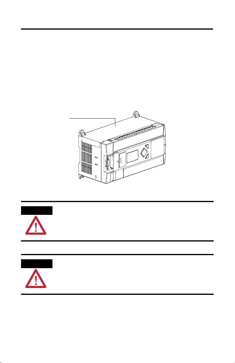
Install your controller using these installation instructions.
Debris strip
(1)
) and with circuits not exceeding Over Voltage
. AC powered products must be connected to the secondary of
44513
ATTENTION
Do not remove the protective debris strip until after the controller and all other
equipment in the panel near the controller are mounted and wiring is complete.
Once wiring is complete, remove protective debris strip. Failure to remove strip
before operating can cause overheating.
ATTENTION
Electrostatic discharge can damage semiconductor devices inside the controller.
Do not touch the connector pins or other sensitive areas.
(1)
Pollution Degree 2 is an environment where, normally, only non-conductive pollution occurs except that occasionally a
temporary conductivity caused by condensation shall be expected.
(2)
Over Voltage Category II is the load level section of the electrical distribution system. At this level transient voltages are
controlled and do not exceed the impulse voltage capability of the product's insulation.
(3)
Pollution Degree 2 and Over Voltage Category II are International Electrotechnical commissions (IEC) designations.
Publication 1766-IN001C-EN-P - October 2009
Page 9
MicroLogix 1400 Programmable Controllers 9
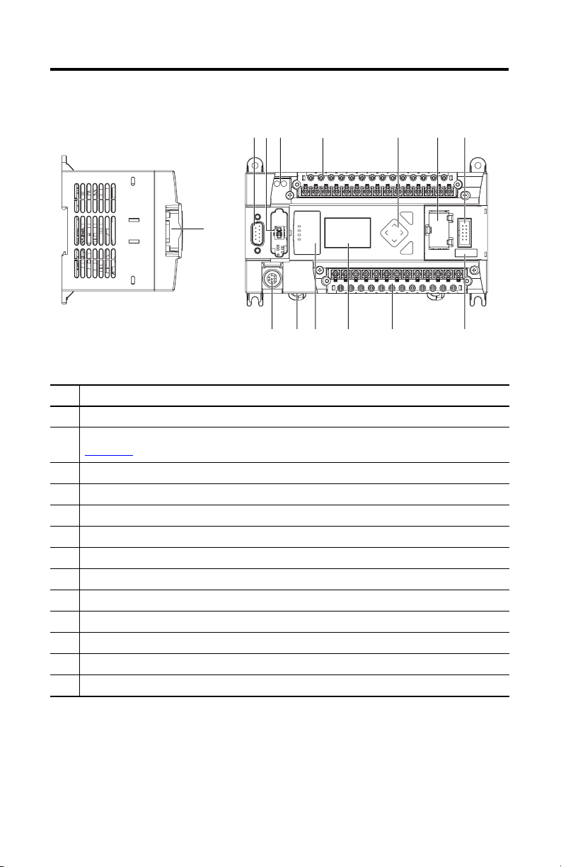
Controller Description
1
256 7
1
44514
Left side view Top view
Description
1 Comm port 2 - 9-pin D-Shell RS-232C connector
2 Memory module (refer to MicroLogix 1400 Memory Module Installation Instructions, publication
1766-IN010
for instructions on installing the memory module).
3 User 24V (for 1766-L32BWA and 1766-L32BWAA only)
4 Input terminal block
5 LCD Display Keypad (ESC, OK, Up, Down, Left, Right)
6 Battery compartment
7 1762 expansion bus connector
8 Battery connector
9 Output terminal block
10 LCD Display
11 Indicator LED panel
12 Comm port 1 - RJ45 connector
13 Comm port 0 - 8-pin mini DIN RS-232C/RS-485 connector
43
ESC
OK
9101113 12
44515
8
Publication 1766-IN001C-EN-P - October 2009
Page 10
10 MicroLogix 1400 Programmable Controllers
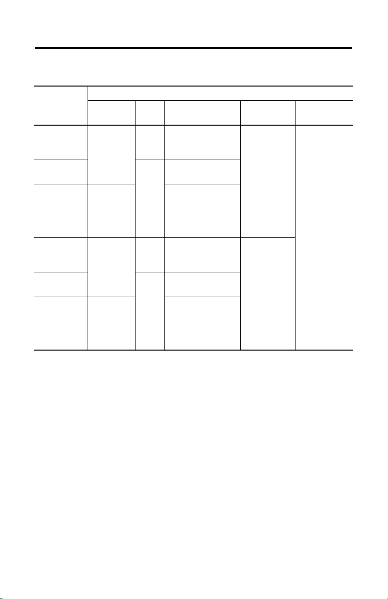
Controller Input and Output Description
Catalog
Number
1766-L32BWA
Description
Input
Power
User
Power
24V DC
100/240V AC
1766-L32AWA
None
1766-L32BXB 24 V DC
1766-L32BWAA
24V DC
100/240V AC
1766-L32AWAA
None
1766-L32BXBA 24V DC
(1)
Isolated RS-232/RS-485 combo port. Same as ML1100 Comm 0
(2)
Non-isolated RS-232. Standard D-sub connector
Embedded
Discrete I/O
12 Fast 24V DC Inputs
8 Normal 24V DC Inputs
12 Relay Outputs
20 120V AC Inputs
12 Relay Outputs
12 Fast 24V DC Inputs
8 Normal 24V DC Inputs
6 Relay Outputs
3 Fast DC Outputs
3 Normal DC Outputs
12 Fast 24V DC Inputs
8 Normal 24V DC Inputs
12 Relay Outputs
20 120V AC Inputs
12 Relay Outputs
12 Fast 24V DC Inputs
8 Normal 24V DC Inputs
6 Relay Outputs
3 Fast DC Outputs
3 Normal DC Outputs
Embedded
Analog I/O
None
4 Voltage Inputs
2 Voltage
Outputs
Comm.
Ports
1 RS232/RS485
1 Ethernet/IP
(2)
1 RS232
(1)
Publication 1766-IN001C-EN-P - October 2009
Page 11
MicroLogix 1400 Programmable Controllers 11
Hazardous Location Considerations
This equipment is suitable for use in Class I, Division 2, Groups A, B, C, D or non-hazardous
locations only. The following WARNING statement applies to use in hazardous locations.
WARNING
EXPLOSION HAZARD
• Substitution of components may impair suitability for Class I, Division 2.
• Do not replace components or disconnect equipment unless power has been switched
off.
• Do not connect or disconnect components unless power has been switched off.
• This product must be installed in an enclosure. All cables connected to the product
must remain in the enclosure or be protected by conduit or other means.
• All wiring must comply with N.E.C. article 501-10(b) and/or in accordance with
Section 18-1J2 of the Canadian Electrical Code, and in accordance with the authority
having jurisdiction.
Use only the following communication cables in Class I, Division 2 hazardous locations.
Environment Classification Communication Cables
Class I, Division 2 Hazardous Environment 1761-CBL-AC00 Series C or later
1761-CBL-AM00 Series C or later
1761-CBL-AP00 Series C or later
1761-CBL-PM02 Series C or later
1761-CBL-HM02 Series C or later
2707-NC9 Series C or later
1763-NC01 Series A or later
1747-CP3 Series
Publication 1766-IN001C-EN-P - October 2009
Page 12
12 MicroLogix 1400 Programmable Controllers
Environnements dangereux
Cet équipement est conçu pour une utilisation en environnements dangereux de Classe I,
Division 2, Groupes A, B, C, D ou non dangereux. La mise en garde suivante s’applique à
utilisation en environnements dangereux.
WARNING
DANGER D’EXPLOSION
• La substitution de composants peut rendre cet équipement impropre à une utilisation
en environnement de Classe I, Division 2.
• Ne pas remplacer de composants ou déconnecter l’équipement sans s’être assuré que
l’alimentation est coupée.
• Ne pas connecter ou déconnecter des composants sans s’être assuré que
l’alimentation est coupée.
• Ce produit doit être installé dans une armoire. Tous les câbles connectés à l’appareil
doivent rester dans l’armoire ou être protégés par une goulotte ou tout autre moyen.
• L’ensemble du câblage doit être conforme à la réglementation en vigueur dans les
pays où l’appareil est installé.
Utilisez uniquement les câbles de communication suivants dans les environnements
dangereux de Classe I, Division 2.
Classification des environnements Câbles de communication
Environnement dangereux de Classe I, Division 2 1761-CBL-AC00 série C ou ultérieure
1761-CBL-AM00 série C ou ultérieure
1761-CBL-AP00 série C ou ultérieure
1761-CBL-PM02 série C ou ultérieure
1761-CBL-HM02 série C ou ultérieure
2707-NC9 série C ou ultérieure
1763-NC01 série A ou ultérieure
série 1747-CP3
ATTENTION
UNSUPPORTED CONNECTION
Do not connect the Comm0 port on the MicroLogix 1400 controller to another MicroLogix
family controller such as MicroLogix 1000, MicroLogix 1200, or MicroLogix 1500 using a
1761-CBL-AM00 (8-pin mini-DIN to 8-pin mini-DIN) cable or equivalent.
This type of connection will cause damage to the RS-232/485 communication port
(Channel 0) of the MicroLogix 1400 and/or the controller itself. Communication pins used
for RS-485 communications are alternately used for 24V power on the other MicroLogix
controllers.
Publication 1766-IN001C-EN-P - October 2009
Page 13
MicroLogix 1400 Programmable Controllers 13
Mount the Controller
General Considerations
Most applications require installation in an industrial enclosure to reduce the effects of
electrical interference and environmental exposure. Locate your controller as far as possible
from power lines, load lines, and other sources of electrical noise such as hard-contact
switches, relays, and ac motor drives. For more information on proper grounding guidelines,
see the Industrial Automation Wiring and Grounding Guidelines, publication 1770-4.1
ATTENTION
Mount the controller horizontally only. Vertical mounting is not supported due to
thermal considerations.
.
ATTENTION
WARNING
WARNING
Be careful of metal chips when drilling mounting holes for your controller or
other equipment within the enclosure or panel. Drilled fragments that fall into
the controller could cause damage. Do not drill holes above a mounted controller
if the protective debris strips have been removed.
Do not place the MicroLogix 1400 Programmable Controller in direct sunlight.
Prolonged exposure to direct sunlight could degrade the LCD display.
The local programming terminal port is intended for temporary use only and
must not be connected or disconnected unless the area is assured to be
nonhazardous.
Publication 1766-IN001C-EN-P - October 2009
Page 14
14 MicroLogix 1400 Programmable Controllers
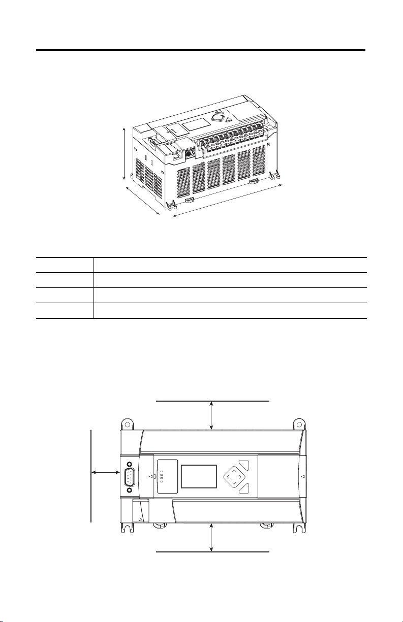
Mounting Dimensions
C
A
B
44516
1766-L32BWA, 1766-L32AWA, 1766-L32BXB,
1766-L32BWAA, 1766-L32AWAA, 1766-L32BXBA
Dimension Height
A 90 mm (3.5 in.)
B 180 mm (7.087 in.)
C 87 mm (3.43 in.)
Controller Spacing
The controller mounts horizontally, with the expansion I/O extending to the right of the
controller. Allow 50 mm (2 in.) of space on all but the right side for adequate ventilation, as
shown below.
Top
ESC
Side
OK
Publication 1766-IN001C-EN-P - October 2009
Bottom
44517
Page 15

MicroLogix 1400 Programmable Controllers 15
DIN Rail Mounting
The maximum extension of the latch is 14 mm (0.55 in.) in the open position. A flat-blade
screwdriver is required for removal of the controller. The controller can be mounted to
EN50022-35x7.5 or EN50022-35x15 DIN rails. DIN rail mounting dimensions are shown
below.
B
A
C
44518
Dimension Height
A 90 mm (3.5 in.)
B 27.5 mm (1.08 in.)
C 27.5 mm (1.08 in.)
Follow these steps to install your controller on the DIN rail.
1. Mount your DIN rail. Make sure that the placement of the controller on the DIN rail
meets the recommended spacing requirements (see Controller Spacing on page 14 for
more information). Refer to the mounting template inside the back cover of this
document.
2. If it is open, close the DIN latch.
3. Hook the top slot over the DIN rail.
4. While pressing the controller down against the top of the rail, snap the bottom of the
controller into position.
5. Leave the protective debris strip attached until you are finished wiring the controller
and any other devices.
Follow these steps to remove your controller from the DIN rail.
1. Place a flat-blade screwdriver in the DIN rail latch at the bottom of the controller.
Publication 1766-IN001C-EN-P - October 2009
Page 16

16 MicroLogix 1400 Programmable Controllers
2. Holding the controller, pry downward on the latch until the latch locks in the open
position.
3. Repeat steps 1 and 2 for the second DIN rail latch.
4. Unhook the top of the DIN rail slot from the rail.
ESC
OK
Open Closed
44519
44520
Panel Mounting
Mount to panel using #8 or M4 screws. Follow these steps to install your controller using
mounting screws.
1. Remove the mounting template from inside the back cover of this document.
2. Secure the template to the mounting surface. Make sure your controller is spaced
properly (see Controller Spacing on page 14 for more information).
3. Drill holes through the template.
4. Remove the mounting template.
5. Mount the controller.
6. Leave the protective debris strip
in place until you are finished
wiring the controller and any
other devices
Mounting Template
ESC
OK
44521
Publication 1766-IN001C-EN-P - October 2009
Page 17

MicroLogix 1400 Programmable Controllers 17
Using the Battery
The MicroLogix 1400 controller is equipped with a replaceable battery (catalog number
1747-BA). The Battery Low indicator on the LCD display of the controller shows the status
of the replaceable battery. When the battery is low, the indicator is set (displayed as a solid
rectangle). This means that either the battery wire connector is disconnected, or the battery
may fail within 2 days if it is connected.
IMPORTANT
WARNING
Follow these steps to connect the replaceable battery.
1. Insert the replaceable battery wire connector into the controller’s battery connector.
The MicroLogix 1400 controller ships with the battery wire connector connected.
Ensure that the battery wire connector is inserted into the connector port if your
application needs battery power. For example, when using a real-time clock
(RTC).
Replacing the battery when the controller is powered down will lose all user
application memory. Replace the battery when the controller is powered on.
Refer to the SLC 500 Lithium Battery Installation Instructions, publication
1747-IN515
disposal of the battery.
When you connect or disconnect the battery an electrical arc can occur. This
could cause an explosion in hazardous location installations. Be sure that the
area is nonhazardous before proceeding.
For Safety information on the handling of lithium batteries, including handling
and disposal of leaking batteries, see Guidelines for Handling Lithium Batteries,
publication AG 5-4
, for more information on installation, handling, usage, storage, and
.
Publication 1766-IN001C-EN-P - October 2009
Page 18

18 MicroLogix 1400 Programmable Controllers
2. Secure the battery connector wires so that it does not block the 1762 expansion bus
connector as shown below.
Battery compartment
Battery
1762 I/O
expansion bus
connector
Battery wire
connector
Battery connector
Battery wires
twisted pair
44522
Connect 1762 I/O Expansion Modules
ATTENTION
Remove power from the system before installing or removing expansion I/O or damage to
the controller may result.
Connect 1762 I/O after mounting the controller.
1. Remove the expansion port cover to install expansion I/O modules.
2. Plug the ribbon cable connector into the bus connector.
Publication 1766-IN001C-EN-P - October 2009
Page 19

MicroLogix 1400 Programmable Controllers 19
3. Replace the cover as shown below.
44523
The MicroLogix 1400 controller is designed to support up to any seven 1762 expansion I/O
modules.
For detailed information on using expansion I/O, refer to the installation instructions for
your expansion module.
Wire the Controller
The shading in the following terminal block illustrations indicates which terminal groups are
tied to which commons.
Terminal Block Layouts
WARNING
WARNING
When you connect or disconnect the Removable Terminal Block (RTB) with field
side power applied, an electrical arc can occur. This could cause an explosion in
hazardous location installations. Be sure that power is removed or the area is
nonhazardous before proceeding.
When used in a Class I, Division 2, hazardous location, this equipment must be
mounted in a suitable enclosure. All wiring must be in accordance with Class I,
Division 2 wiring methods of Article 501 of the National Electrical Code and/or
in accordance with Section 18-1J2 of the Canadian Electrical Code, and in
accordance with the authority having jurisdiction.
Publication 1766-IN001C-EN-P - October 2009
Page 20

20 MicroLogix 1400 Programmable Controllers
1766-L32BWA/L32BWAA
Input Terminal Block
COM 1
IN1
VAC
L2/N
Group 0 Group 1 Group 2 Group 3 Group 5Group 4 Group 6
IN4 IN6
IN3
OUT0
OUT1 OUT2 OUT3 OUT4
DC1
DC0
VAC
VAC
COM 0
VAC
IN0 IN2
L1
1766-L32AWA/L32AWAA
COM 1
IN5 IN7
IN4 IN6
IN3
COM 0
IN0 IN2
IN1
IN5 IN7
DC2
VAC
IN8 IN10
COM 2
IN9 IN11
DC3
DC4
VAC
OUT5
VAC
Output Terminal Block
Input Terminal Block
IN8 IN10
COM 2
IN9 IN11
COM 3
IN13 IN15 IN17 IN19
IN12 IN14 IN16 IN18
VAC
OUT7 OUT8 OUT10
DC5
DC6
OUT6 OUT9 OUT11
VAC
COM 3
IN13 IN15 IN17 IN19
IN12 IN14 IN16 IN18
COM
ANA
OV0
COM
ANA
IV0(+) IV2(+)
COM
ANA
OV1
IV0(+) IV2(+)
IV1(+) IV3(+)
44524
IV1(+) IV3(+)
VAC
VAC
OUT0
L1
L2/N
OUT1 OUT2 OUT3 OUT4
DC1
DC2
DC3
DC4
DC0
VAC
VAC
VAC
VAC
Group 0 Group 1 Group 2 Group 3 Group 5Group 4 Group 6
OUT5
VAC
Output Terminal Block
Publication 1766-IN001C-EN-P - October 2009
VAC
DC5
OUT7 OUT8 OUT10
DC6
OUT6 OUT9 OUT11
VAC
COM
ANA
OV1
OV0
44525
Page 21

1766-L32BXB/L32BXBA
MicroLogix 1400 Programmable Controllers 21
Input Terminal Block
IN9 IN11
OUT7
COM 3
IN13 IN15 IN17 IN19
IN12 IN14 IN16 IN18
OUT8 OUT9 OUT10
COM 2
DC3
VAC
VAC
IV0(+) IV2(+)
COM
IV1(+) IV3(+)
ANA
COM
ANA
OV1
DC5
OUT11
VAC
OV0
44526
IN0 IN2
COM 0
IN1
IN3
VDC
VDC
+24
OUT0
NEUT
DC0
VAC
Group 0 Group 1 Group 3 Group 4 Group 5Group 2
COM 1
IN5 IN7
IN4 IN6
OUT1 OUT2 OUT4 OUT6
DC1
VDC2 OUT3 OUT5 DC4
VAC
IN8 IN10
COM 2
Wire Type Wire Size
Solid wire Cu-90°C (194°F) 14…22 AWG
Stranded wire Cu-90°C (194°F) 16…22 AWG
Wiring torque = 0.791Nm (7 in-lb) rated.
Output Terminal Grouping
Outputs
Controller Output Group Description Voltage Terminal Output Terminal
1766-L32BWA
766-L32BWAA
1
Group 0 Isolated relay output VAC/DC0 OUT 0
Group 1 Isolated relay output VAC/DC1 OUT 1
Group 2 Isolated relay output VAC/DC2 OUT 2
Group 3 Isolated relay output VAC/DC3 OUT 3
Group 4 Isolated relay output VAC/DC4 OUT 4, OUT 5
Group 5 Isolated relay output VAC/DC5 OUT 6, OUT 7
Group 6 Isolated relay output VAC/DC6 OUT 8…11
Publication 1766-IN001C-EN-P - October 2009
Page 22

22 MicroLogix 1400 Programmable Controllers
Output Terminal Grouping
Outputs
Controller Output Group Description Voltage Terminal Output Terminal
1766-L32AWA
1766-L32AWAA
Group 0 Isolated relay output VAC/DC0 OUT 0
Group 1 Isolated relay output VAC/DC1 OUT 1
Group 2 Isolated relay output VAC/DC2 OUT 2
Group 3 Isolated relay output VAC/DC3 OUT 3
Group 4 Isolated relay output VAC/DC4 OUT 4, OUT 5
Group 5 Isolated relay output VAC/DC5 OUT 6, OUT 7
Group 6 Isolated relay output VAC/DC6 OUT 8…11
1766-L32BXB
1766-L32BXBA
WARNING
WARNING
Group 0 Isolated relay output VAC/DC0 OUT 0
Group 1 Isolated relay output VAC/DC1 OUT 1
Group 2 FET output VDC2/COM 2 OUT 2…7
Group 3 Isolated relay output VAC/DC3 OUT 8
Group 4 Isolated relay output VAC/DC4 OUT 9
Group 5 Isolated relay output VAC/DC5 OUT 10, OUT 11
If you connect or disconnect wiring while the field-side power is on, an electrical
arc can occur. This could cause an explosion in hazardous location installations.
Be sure that power is removed or the area is nonhazardous before proceeding
The local programming terminal port is intended for temporary use only and
must not be connected or disconnected unless the area is free of ignitable
concentrations of flammable gases or vapors.
Publication 1766-IN001C-EN-P - October 2009
Page 23

MicroLogix 1400 Programmable Controllers 23
Wiring Recommendation
When wiring without spade lugs, keep the finger-safe covers in place. Loosen the terminal
screw and route the wires through the opening in the finger-safe cover. Tighten the terminal
screw, making sure the pressure plate secures the wire.
Finger-safe cover
44527
ATTENTION
Be careful when stripping wires. Wire fragments that fall into the controller
could cause damage. Once wiring is complete, be sure the controller is free of
all metal fragments before removing the protective debris strip. Failure to
remove the strip before operating can cause overheating.
Publication 1766-IN001C-EN-P - October 2009
Page 24

24 MicroLogix 1400 Programmable Controllers
Spade Lug Recommendation
The diameter of the terminal screw head is 5.5 mm (0.220 in.). The input and output
terminals of the MicroLogix 1400 controller are designed for the following spade lugs. The
terminals will accept a 6.35mm (0.25 in.) wide spade (standard for #6 screw for up to 14
AWG) or a 4 mm (metric #4) fork terminal.
When using spade lugs, use a small, flat-blade screwdriver to pry the finger-safe cover from
the terminal blocks, then loosen the terminal screw.
Finger-safe cover
44528
TIP
If you wire the terminal block with the finger-safe cover removed, you may not
be able to put it back on the terminal block if the wires are in the way.
Surge Suppression
ATTENTION
Publication 1766-IN001C-EN-P - October 2009
Inductive load devices such as motor starters and solenoids require the use of
some type of surge suppression to protect the controller output. Switching
inductive loads without surge suppression can significantly reduce the life of
relay contacts or damage transistor outputs. By using suppression, you also
reduce the effects of voltage transients caused by interrupting the current to
that inductive device, and prevent electrical noise from radiating into system
wiring. Refer to the MicroLogix 1400 Programmable Controller User Manual,
publication 1766-UM001
, for more information on surge suppression.
Page 25

MicroLogix 1400 Programmable Controllers 25
Grounding the Controller
In solid-state control systems, grounding and wire routing helps limit the effects of noise due
to electromagnetic interference (EMI). Run the ground connection from the ground screw of
the controller to the ground bus prior to connecting any devices. Use AWG #14 wire. For
AC-powered controllers, this connection must be made for safety purposes.
You must also provide an acceptable grounding path for each device in your application. For
more information on proper grounding guidelines, refer to the Industrial Automation Wiring
and Grounding Guidelines, publication 1770-4.1
.
Wiring Your Analog Channels
Analog input circuits can monitor voltage signals and convert them to serial digital data as
shown in the following illustration.
Analog Input
Sensor 2
(V) Voltage
Sensor 0
(V) Voltage
Input Terminal Block
I/9 I/11
COM 3
Sensor 1
(V) Voltage
/7
I/8 I/10
COM 2
I/13 I/15 I/17 I/19
I/12 I/14 I/16 I/18
Sensor 3
(V) Voltage
Publication 1766-IN001C-EN-P - October 2009
IV0(+) IV2(+)
COM
ANA
IV1(+) IV3(+)
44529
Page 26

26 MicroLogix 1400 Programmable Controllers
The controller does not provide loop power for analog inputs. Use a power supply that
matches the transmitter specifications as shown.
The analog output can support a voltage function as shown in the following illustration.
Analog Output
Voltage Load
COM
ANA
OV1O/3 O/4
OV0
3CDC4
VAC
VAC
DC5
O/7 O/8 O/10
O/5
O/6 O/9 O/11
DC6
VAC
Output Terminal Block
Analog Input Transmitter Specifications
2-Wire Transmitter
+
Transmitter
+-
-
3-Wire Transmitter
Powe r
+
Supply
-
Transmitter
Supply Signal
GND
Voltage Load
44680
Controller
IV0(+), IV1(+), IV2(+) or IV3(+)
COM ANA
Controller
IV0(+), IV1(+), IV2(+) or IV3(+)
COM ANA
4-Wire Transmitter
+
Powe r
Supply
-
Transmitter
Supply Signal
+-+
-
Publication 1766-IN001C-EN-P - October 2009
Controller
IV0(+), IV1(+), IV2(+) or IV3(+)
COM ANA
44530
Page 27

MicroLogix 1400 Programmable Controllers 27
Minimizing Electrical Noise on Analog Channels
Inputs on analog channels employ digital high-frequency filters that significantly reduce the
effects of electrical noise on input signals. However, because of the variety of applications and
environments where analog controllers are installed and operated, it is impossible to ensure
that all environmental noise will be removed by the input filters.
Several specific steps can be taken to help reduce the effects of environmental noise on
analog signals:
• Install the MicroLogix 1400 system in a properly rated (NEMA) enclosure. Make sure
that the MicroLogix 1400 system is properly grounded.
• Use Belden cable #8761 for wiring the analog channels, making sure that the drain
wire and foil shield are properly earth grounded, (see Grounding Your Analog Cable
on page 27 for more information).
• Route the Belden cable separately from any AC wiring. Additional noise immunity can
be obtained by routing the cables in grounded conduit.
Grounding Your Analog Cable
Use shielded communication cable
(Belden #8761). The Belden cable
has two signal wires (black and
clear), one drain wire, and a foil
shield. The drain wire and foil
shield must be grounded at one
end of the cable.
Insulation
Foil Shield
Black Wire
Drain Wire
IMPORTANT
Clear Wire
44531
Do not ground the drain wire and foil shield at both ends of the cable.
Publication 1766-IN001C-EN-P - October 2009
Page 28

28 MicroLogix 1400 Programmable Controllers
Specifications
General Specifications
Description 1766-L32AWA
1766-L32AWAA
Dimensions
HxWxD
90 x 180 x 87 mm
3.5 x 7.087 x 3.43 in.
1766-L32BWA
1766-L32BWAA
1766-L32BXB
1766-L32BXBA
Shipping weight 0.9 kg (2.0 lbs)
Number of I/O 24 inputs (20 digital and 4 analog) and 14 outputs (12 digital and 2 analog)
Power supply voltage 100…240V AC (-15%, +10%) @ 47…63 Hz 24V DC (-15%, +10%) Class
2 SELV
Heat dissipation Refer to the MicroLogix 1400 Programmable Controllers User Manual,
.
24V DC:
15 A for 20 ms
Power supply inrush
current
Publication 1766-UM001
120V AC: 25 A for 8 ms
240V AC: 40A for 4 ms
Power consumption 100 VA 120 VA 50W
7.5W (with no 1762
expansion I/O)
24V DC sensor power none 24V DC @ 250 mA
none
400 µF max.
Input circuit type Digital: 120V AC
Analog: 0…10V DC
Digital: 24V DC
sink/source
(standard and high-speed)
Analog: 0…10V DC
Digital: 24V DC
sink/source
(standard and high-speed)
Analog: 0…10V DC
Output circuit type Relay Relay/FET
Relay life - Electrical
5
operations min (2.5 A, 250V AC / 30V DC)
2 x 10
Enclosure type rating None (open-style)
Wire size
0.25… 2.5 mm
2
(22…14 AWG) solid or stranded copper wire rated @ 90 °C
(194 °F) or greater.
Wiring category
(1)
2 - on signal ports
2 - on power ports
3 - on communications ports
Terminal screw torque 0.79 Nm (7.0 in-lb) rated
Pilot duty rating R300, C300
Expansion bus Supports up to seven 1762 modules, up to a maximum of 5V, 1500 mA and 24 V,
1500 mA.
North American temp code T3C
(1)
Use this Conductor Category information for planning conductor routing. Refer to Industrial Automation Wiring and
Grounding Guidelines, publication 1770-4.1
.
Publication 1766-IN001C-EN-P - October 2009
Page 29

MicroLogix 1400 Programmable Controllers 29
Specifications for Inputs
Digital Inputs
Description 1766-L32AWA
On-state voltage
range
Off-state voltage
range
Operating
frequency
On-state current
min
nom
max
Off-state leakage
current
Nominal
impedance
Inrush current
(max.) @ 120V AC
1766-L32AWAA
79…132 V AC 4.5…24V DC, Class 2
0…20 V AC 0…1.5V DC 0…5V DC
47…63 Hz 0 Hz…100 kHz 0 Hz…1 kHz
5.0 mA @ 79 V AC
12 mA @ 120 V AC
16.0 mA @ 132 V AC
2.5 mA max. 0.2 mA max. 1.5 mA max.
12 kΩ @ 50 Hz
10 kΩ @ 60 Hz
250 mA
1766-L32BWA, 1766-L32BWAA, 1766-L32BXB,
1766-L32BXBA
Inputs 0 through 11
(12 high-speed DC inputs)
(4.5…26.4V DC @ 60°C/140°F)
(4.5…30V DC @ 30°C/86°F)
7.1 mA @ 4.5V DC
9.9 mA @ 24V DC
10.5 mA @ 30V DC
2.4 kΩ 4.5 kΩ
Inputs 12 and higher
(8 standard DC inputs)
10…24V DC, Class 2
(10…26.4V DC @ 60°C/140°F)
(10…30V DC @ 30°C/86°F)
(scan time dependent)
3.2 mA @ 10V DC
5.3 mA @ 24V DC
5.5 mA @ 30V DC
Analog Inputs
Description 1766-L32AWAA, -L32BWAA, -L32BXBA
Voltage input range 0…10.0V DC - 1 LSB
Type of data 12-bit unsigned integer
Input coding (0…10.0V DC - 1 LSB) 0…4,095
Voltage input impedance >199 kΩ
Input resolution 12 bit
Non-linearity
Overall accuracy
-20…60 °C (-4…140 °F)
Voltage input overvoltage protection 10.5 V DC
Field wiring to logic isolation Non-isolated with internal logic
±1.0% of full scale
±1.0% of full scale
Publication 1766-IN001C-EN-P - October 2009
Page 30

30 MicroLogix 1400 Programmable Controllers
Analog Outputs
Description 1766-L32AWAA, -L32BWAA, -L32BXBA
Number of inputs 2 single-ended
Voltage output range 0…10 V DC - 1 LSB
Type of data 12 bit unsigned integer
Step response 2.5 ms @ 95%
Load range
Voltage output 1 KΩ
Output resolution 12 bit
Analog output setting time 3 ms (max.)
Overall Accuracy
-20…60 °C (-4…140 °F)
Electrical isolation Non-isolated with internal logic
Cable length 30 m (98 ft) shielded cable
±1.0% of full scale
Relay and FET Outputs
Description 1766-L32AWA, 1766-L32AWAA,
1766-L32BWA, 1766-L32BWAA
Maximum controlled load 1440 VA 1080 VA
Maximum Continuous Current:
Current per channel and group common 2.5 A per channel
8A max channel 8…11 common
Current per controller at 150V max 28 A or total of per-point loads,
whichever is less
at 240V max 20 A or total of per-point loads,
whichever is less
1766-L32BXB,
1766-L32BXBA
2.5 A per channel
Relay Outputs
Description 1766-L32AWA, 1766-L32AWAA, 1766-L32BWA,
Turn On Time/Turn Off Time
Load current 10 mA (minimum)
(1)
Scan time dependent
Publication 1766-IN001C-EN-P - October 2009
1766-L32BWAA, 1766-L32BXB, 1766-L32BXBA
10 ms (maximum)
(1)
Page 31

MicroLogix 1400 Programmable Controllers 31
Maximum Volts Amperes Amperes
Make Break Make Break
Continuous
Volt-Amperes
240V AC 7.5 A 0.75 A 2.5 A 1800 VA 180 VA
120V AC 15.0 A 1.5 A 2.5 A 1800 VA 180 VA
250V DC 0.11 A 1.0 A 28 VA
125V DC 0.22 A 1.0 A 28 VA
1766-L32BXB, 1766-L32BXBA FET Output
Maximum output current (temperature dependent):
FET Current per Point FET Total Current
2.0
1.75
1.25
0.75
Current (Amps)
0.25
1.5
1.0
0.5
1.5A, 30°C (86°F)
Valid
Range
10°C
(50°F)
30°C
(86°F)
Temperature
50°C
(122°F)
0.75A, 60°C (140°F)
70°C
80°C
(158°F)
(176°F)
44532 44533
8.0
7.0
Valid
Range
(86°F)
30°C
6.0A , 30°C (86°F)
50°C
(122°F)
3.0A , 60°C (140°F)
70°C
(158°F)
6.0
5.0
4.0
3.0
2.0
Current (Amps)
1.0
10°C
(50°F)
Temperature
80°C
(176°F)
Description General Operation
Power supply voltage 24V DC (-15%, 10%) Class 2
On-state voltage drop:
at max load current
at max surge current
1V DC
2.5V DC
Current rating per point
max load
min load
max leakage
See graphic above
1.0 mA
1.0 mA
Surge current per point:
peak current
max surge duration
max rate of repetition @ 30 °C (86 °F)
max rate of repetition @ 60 °C (140 °F)
4.0 A
10 ms
once every second
once every 2 seconds
Publication 1766-IN001C-EN-P - October 2009
High Speed Operation
(Output 2, 3 and 4 Only)
Not Applicable
Not Applicable
100 mA
20 mA
1.0 mA
Not Applicable
Not Applicable
Not Applicable
Not Applicable
(1)
Page 32

32 MicroLogix 1400 Programmable Controllers
Description General Operation
Turn-On Time (maximum) 11 µs 28 ns
Turn-Off Time (maximum) 89 µs2.3 µs
(1)
Output 2, 3 and 4 are designed to provide increased functionality over the other FET outputs. Output 2, 3 and 4 may be used
like the other FET transistor outputs, but in addition, within a limited current range, they may be operated at a higher speed.
Output 2, 3 and 4 also provide a pulse train output (PTO) or pulse width modulation output (PWM) function.
High Speed Operation
(Output 2, 3 and 4 Only)
Working Voltage
Working Voltage for 1766-L32AWA, 1766-L32AWAA
Description Recommendation
Power supply input to
backplane isolation
Input group to backplane
isolation
Input group to input group
isolation
Output group to backplane
isolation
Output group to output
group isolation
Verified by one of the following dielectric tests: 1836V AC for 1 second or
2596V DC for 1 second
265V AC Working Voltage (IEC Class 2 reinforced insulation)
Verified by one of the following dielectric tests:1517V AC for 1 second or
2145V DC for 1 second
132V AC Working Voltage (IEC Class 2 reinforced insulation)
Verified by one of the following dielectric tests:1517V AC for 1 second or
2145V DC for 1 second
132V AC Working Voltage (basic insulation)
Verified by one of the following dielectric tests: 1836V AC for 1 second or
2596V DC for 1 second
265V AC Working Voltage (IEC Class 2 reinforced insulation)
Verified by one of the following dielectric tests: 1836V AC for 1 second or
2596V DC for 1second
265V AC Working Voltage (basic insulation), 150V AC Working Voltage (IEC
Class 2 reinforced insulation)
(1)
Publication 1766-IN001C-EN-P - October 2009
Page 33

MicroLogix 1400 Programmable Controllers 33
Working Voltage for 1766-L32BWA, 1766-L32BWAA
Description Recommendation
Power supply input to
backplane isolation
Input group to backplane
isolation and input group to
input group isolation
Output group to backplane
Isolation
Output group to output
group isolation
Verified by one of the following dielectric tests:1836V AC for 1 second or
2596V DC for 1 second
265V AC Working Voltage (IEC Class 2 reinforced insulation)
Verified by one of the following dielectric tests: 1100V AC for 1 second or
1697V DC for 1 second
75V DC Working Voltage (IEC Class 2 reinforced insulation)
Verified by one of the following dielectric tests: 1836V AC for 1 second or
2596V DC for 1 second
265V AC Working Voltage (IEC Class 2 reinforced insulation).
Verified by one of the following dielectric tests: 1836V AC for 1 second or
2596V DC for 1 second
265V AC Working Voltage (basic insulation) 150V Working Voltage (IEC Class 2
reinforced insulation)
Working Voltage for 1766-L16BXB, 1766-L16BXBA
Description Recommendation
Input group to backplane
isolation and input group to
input group isolation
FET output group to
backplane isolation
Relay output group to
backplane isolation
Relay output group to relay
output group and FET output
group isolation
Verified by one of the following dielectric tests: 1100V AC for 1 second or
1697V DC for 1 second
75V DC Working Voltage (IEC Class 2 reinforced insulation)
Verified by one of the following dielectric tests: 1100V AC for 1 second or
1697V DC for 1 second
75V DC Working Voltage (IEC Class 2 reinforced insulation)
Verified by one of the following dielectric tests: 1836V AC for 1 second or
2596V DC for 1 second
265V AC Working Voltage (IEC Class 2 reinforced insulation)
Verified by one of the following dielectric tests: 1836V AC for 1 second or
2596V DC for 1 second
265V AC Working Voltage (basic insulation), 150V Working Voltage
(IEC Class 2 reinforced insulation)
Publication 1766-IN001C-EN-P - October 2009
Page 34

34 MicroLogix 1400 Programmable Controllers
Environmental Specifications
Description 1766-L32AWA
1766-L32AWAA
Temperature, operating IEC 60068-2-1 (Test Ad, Operating Cold),
IEC 60068-2-2 (Test Bd, Operating Dry Heat),
IEC 60068-2-14 (Test Nb, Operating Thermal Shock):
-20… 60 °C (-4…140 °F)
Temperature, storage IEC 60068-2-1 (Test Ab, Unpackaged Non-operating Cold),
IEC 60068-2-2 (Test Bb, Unpackaged Non-operating Dry Heat),
IEC 60068-2-14 (Test Na, Unpackaged Non-operating Thermal Shock):
-40…85 °C (-40…185 °F)
Relative humidity IEC 60068-2-30 (Test Db, Unpackaged Damp Heat):
5…95% non-condensing
Vibration IEC 60068-2-6 (Test Fc, Operating):
3 g @ 10… 500 Hz
Shock, operating IEC 60068-2-27 (Test Ea, Unpackaged Shock):
30 g
Shock, nonoperating IEC 60068-2-27 (Test Ea, Unpackaged Shock):
Panel mount - 50 g
DIN mount - 40 g
Emissions CISPR 11
Group 1, Class A
ESD immunity IEC 61000-4-2:
4 kV contact discharges
8 kV air discharges
Radiated RF immunity IEC 61000-4-3:
10V/m with 1 kHz sine-wave 80% AM from 80…1000 MHz
3 V/m with 1 kHz sine-wave 80% AM from 1.4…2.0 GHz
1 V/m with 1 kHz sine-wave 80% AM from 2.0…2.7 GHz
EFT/B immunity IEC 61000-4-4:
±2 kV @ 5 kHz on power ports
±2 kV @ 5 kHz on signal ports
±1 kV @ 5 kHz on communications ports
1766-L32BWA
1766-L32BWAA
1766-L32BXB
1766-L32BXBA
Publication 1766-IN001C-EN-P - October 2009
Page 35

MicroLogix 1400 Programmable Controllers 35
Description 1766-L32AWA
1766-L32AWAA
Surge transient
immunity
Conducted RF immunity IEC 61000-4-6:
Voltage variation IEC 6100-4-11:
IEC 61000-4-5:
±1 kV line-line(DM) and ±2 kV line-earth(CM) on AC power ports
±1 kV line-line(DM) and ±2 kV line-earth(CM) on signal ports
±1 kV line-earth(CM) on communications ports
10V rms with 1 kHz sine-wave 80% AM from 150 kHz…80 MHz
60% dip for 10 periods on AC supply ports
30% dips for 25 periods @ 0° and 180° on AC supply ports
100% dip for 250 periods @ 0° and 180° on AC supply ports
100% dip for 0.5 periods, arbitrary angle, on AC supply ports
1766-L32BWA
1766-L32BWAA
1766-L32BXB
1766-L32BXBA
Certifications for 1766-L32AWA, 1766-L32AWAA, 1766-L32BWA, 1766-L32BWAA, 1766-L32BXB, 1766-L32BXBA
Certification (when
product is marked)
UL UL Listed for Class I, Division 2 Group A,B,C,D Hazardous Locations.
c-UL UL Listed for Class I, Division 2 Group A,B,C,D Hazardous Locations, certified for
CE European Union 2004/108/EC EMC Directive, compliant with:
C-Tick Australian Radiocommunications Act, compliant with:
(1)
See the Product Certification link at http://www.ab.com for Declaration of Conformity, Certificates, and other certification
details.
Valu e
(1)
See UL File E10314.
Canada. See UL File E10314.
EN 61000-6-2; Industrial Immunity
EN 61000-6-4; Industrial Emissions
EN 61131-2; Programmable Controllers (Clause 8, Zone A & B)
EN 61131-2; Programmable Controllers (Clause 11)
AS/NZS CISPR 11; Industrial Emissions
Publication 1766-IN001C-EN-P - October 2009
Page 36

36 MicroLogix 1400 Programmable Controllers
Publication 1766-IN001C-EN-P - October 2009
Page 37

0.164
180.0 mm
(7.087 in.)
165.8 mm
(6.528 in.)
25.81 mm
(1.016 in.)
100.06 mm
(3.939 in.)
DIN rail center line.
Ligne médiane du rail DIN.
Mittellinie der DIN-Schiene.
Línea central del riel DIN.
Linea centrale della guida DIN.
linha de centro do trilho DIN.
Expansion I/O
Extension d'E/S
E/A Erweiterungsmodule
Espansione dei
moduli I/O
Expansión de E/S
Expansão de E/S
1766-L32AWA, 1766-L32AWAA
1766-L32BWA, 1766-L32BWAA
1766-L32BXB, 1766-L32BXBA
Page 38

INPUTS
INPUTS
OUTPUTS
01 23456 7891011
0 1 2 3 4 5 6 7 8 9 10 111213 141516 171819
OUTPUTS
0 1 2 3 4 5 6 7 8 9 10 111213 141516 171819
01 23456 7891011
L32AWAAL32AWA
Page 39

1766-L32AWAA
1766-L32AWAA
1766-L32AWA
1766-L32AWA
0
IN1 IN3 IN4 IN6 IN9 IN11 IN12 IN14 IN16 IN18 IV1 IV3
2
ANA
COM
COM
COM
1
3
IN0 IN2 IN5 IN7 IN8
COM
IN10 IN13 IN15 IN17 IN19
COM
IV0 IV2
DC0
DC1
DC2
DC3
DC4
5
6
DC6
9
11
OV0
VAC
VAC
VAC
VAC
VAC
OUT
OUT
VAC
OUT
OUT
L1
L2/N
0
1
2
3
4
DC5
7
8
10
ANA
OV1
VAC
VAC
OUT
OUT
OUT
OUT
OUT
VAC
OUT
OUT
OUT
COM
COM
0
IN0 IN2 IN5 IN7 IN8
IN1 IN3 IN4 IN6 IN9 IN11 IN12 IN14 IN16 IN18 NC
DC0
COM
1
COM
2
IN10 IN13 IN15 IN17 IN19
COM
3
NC
NC NC
DC1
DC2
DC4
5
6
9
11
DC3
DC6
NC
VAC
VAC
VAC
VAC
VAC
OUT
OUT
VAC
OUT
OUT
L1
L2/N
0
1
2
3
4
DC5
7
8
10
NC
NC
VAC
VAC
OUT
OUT
OUT
OUT
OUT
VAC
OUT
OUT
OUT
L32AWAA
NC
L32AWA
953203-16
Page 40

INPUTS
INPUTS
OUTPUTS
01 23456 7891011
0 1 2 3 4 5 6 7 8 9 10 111213 141516 171819
OUTPUTS
0 1 2 3 4 5 6 7 8 9 10 111213 141516 171819
01 23456 7891011
L32BWAAL32BWA
Page 41

1766-L32BWAA
1766-L32BWAA
1766-L32BWA
1766-L32BWA
0
IN1 IN3 IN4 IN6 IN9 IN11 IN12 IN14 IN16 IN18 IV1 IV3
2
ANA
COM
COM
COM
1
3
IN0 IN2 IN5 IN7 IN8
COM
IN10 IN13 IN15 IN17 IN19
COM
IV0 IV2
DC0
DC1
DC2
DC3
DC4
5
6
DC6
9
11
OV0
VAC
VAC
VAC
VAC
VAC
OUT
OUT
VAC
OUT
OUT
L1
L2/N
0
1
2
3
4
DC5
7
8
10
ANA
VAC
VAC
OUT
OUT
OUT
OUT
OUT
VAC
OUT
OUT
OUT
COM
OV1
COM
0
IN0 IN2 IN5 IN7 IN8
IN1 IN3 IN4 IN6 IN9 IN11 IN12 IN14 IN16 IN18 NC
DC0
COM
1
COM
2
IN10 IN13 IN15 IN17 IN19
COM
3
NC
NC NC
DC1
DC2
DC4
5
6
9
11
DC3
DC6
NC
VAC
VAC
VAC
VAC
VAC
OUT
OUT
VAC
OUT
OUT
L1
L2/N
0
1
2
3
4
DC5
7
8
10
NC
NC
VAC
VAC
OUT
OUT
OUT
OUT
OUT
VAC
OUT
OUT
OUT
NC
L32BWAL32BWAA
953203-16
Page 42

INPUTS
INPUTS
OUTPUTS
01 23456 7891011
0 1 2 3 4 5 6 7 8 9 10 111213 141516 171819
OUTPUTS
0 1 2 3 4 5 6 7 8 9 10 111213 141516 171819
01 23456 7891011
L32BXBL32BXBA
Page 43

1766-L32BXB
1766-L32BXBA
1766-L32BXB
COM
0
IN0 IN2 IN5 IN7 IN8
IN1 IN3 IN4 IN6 IN9 IN11 IN12 IN14 IN16 IN18 NC
COM
1
COM
2
IN10 IN13 IN15 IN17 IN19
COM
3
NC
NC NC
DC0
DC1
2
3
5
7
DC3
DC4
DC5
11
NC
VAC
VAC
VDC
OUT
OUT
OUT
VAC
VAC
VAC
OUT
VDC
+24
NEUT
VDC
OUT
0
OUT
1
OUT
2
OUT
4
OUT
6
COM
2
OUT
8
OUT
9
OUT
10
NC
NC
0
IN1 IN3 IN4 IN6 IN9 IN11 IN12 IN14 IN16 IN18 IV1 IV3
2
ANA
COM
COM
COM
1
3
IN0 IN2 IN5 IN7 IN8
COM
IN10 IN13 IN15 IN17 IN19
COM
IV0 IV2
1766-L32BXBA
VDC
NEUT
VAC
DC0
0
VAC
DC1
1
VDC
2
2
OUT
3
4
OUT
5
6
OUT
7
2
DC3
VAC
8
VAC
DC4
9
VAC
DC5
10
OUT
11
ANA
OV0
+24
VDC
OUT
OUT
OUT
OUT
OUT
COM
OUT
OUT
OUT
COM
OV1
NC
L32BXBAL32BXB
953203-16
Page 44

Publication 1766-IN001C-EN-P - October 2009
Page 45

Rockwell Automation Support
Rockwell Automation provides technical information on the Web to assist you in using its products. At
http://support.rockwellautomation.com
technical and application notes, sample code and links to software service packs, and a MySupport feature
that you can customize to make the best use of these tools.
For an additional level of technical phone support for installation, configuration and troubleshooting, we
offer TechConnect support programs. For more information, contact your local distributor or Rockwell
Automation representative, or visit http://support.rockwellautomation.com
Installation Assistance
If you experience a problem with a hardware module within the first 24 hours of installation, please
review the information that's contained in this manual. You can also contact a special Customer Support
number for initial help in getting your module up and running:
United States 1.440.646.3434 Monday – Friday, 8am – 5pm EST
Outside United States Please contact your local Rockwell Automation representative for any technical
support issues.
New Product Satisfaction Return
Rockwell Automation tests all of its products to ensure that they are fully operational when shipped from
the manufacturing facility. However, if your product is not functioning and needs to be returned, follow
these procedures.
United States Contact your distributor. You must provide a Customer Support case number (see
Outside United States Please contact your local Rockwell Automation representative for return procedure.
Allen-Bradley, Rockwell Automation, MicroLogix, and TechConnect are trademarks of Rockwell Automation, Inc.
Trademarks not belonging to Rockwell Automation are property of their respective companies.
phone number above to obtain one) to your distributor in order to complete the return
process.
, you can find technical manuals, a knowledge base of FAQs,
.
Publication 1766-IN001C-EN-P - October 2009 PN 953203-13(04)
Supersedes publication 1766-IN001B-EN-P - November 2008 Copyright © 2009 Rockwell Automation, Inc. All rights reserved. Printed in Singapore.
 Loading...