

Rockwell Automation 1766-L32AWA, 1766-L32AWAA, 1766-L32BWA, 1766-L32BXBA, 1766-L32BWAA Installation Instructions Manual
...
Installation Instructions
MicroLogix 1400 Programmable Controllers
Catalog Number(s) 1766-L32AWA, 1766-L32AWAA,
1766-L32BWA, 1766-L32BWAA, 1766-L32BXB,
1766-L32BXBA
Topic Page
Important User Information 2
Additional Resources 5
Overview 6
Controller Description 7
Hazardous Location Considerations 9
Mount the Controller 11
Connect 1762 I/O Expansion Modules 16
Wire the Controller 17
Specifications 26
2 MicroLogix 1400 Programmable Controllers
WARNING
IMPORTANT
ATTENTION
SHOCK HAZARD
BURN HAZARD
Important User Information
Solid state equipment has operational characteristics differing from those of electromechanical equipment.
Safety Guidelines for the Application, Installation and Maintenance of Solid State Controls (Publication
SGI-1.1 available from your local Rockwell Automation sales office or online at
http://literature.rockwellautomation.com
equipment and hard-wired electromechanical devices. Because of this difference, and also because of the
wide variety of uses for solid state equipment, all persons responsible for applying this equipment must
satisfy themselves that each intended application of this equipment is acceptable.
In no event will Rockwell Automation, Inc. be responsible or liable for indirect or consequential damages
resulting from the use or application of this equipment.
The examples and diagrams in this manual are included solely for illustrative purposes. Because of the many
variables and requirements associated with any particular installation, Rockwell Automation, Inc. cannot
assume responsibility or liability for actual use based on the examples and diagrams.
No patent liability is assumed by Rockwell Automation, Inc. with respect to use of information, circuits,
equipment, or software described in this manual.
Reproduction of the contents of this manual, in whole or in part, without written permission of Rockwell
Automation, Inc., is prohibited.
Throughout this manual, when necessary, we use notes to make you aware of safety considerations.
) describes some important differences between solid state
Identifies information about practices or circumstances that can cause an explosion in
a hazardous environment, which may lead to personal injury or death, property
damage, or economic loss.
·
Identifies information that is critical for successful application and understanding of
the product.
Identifies information about practices or circumstances that can lead to personal injury
or death, property damage, or economic loss. Attentions help you identify a hazard,
avoid a hazard and recognize the consequences.
Labels may be on or inside the equipment (for example, drive or motor) to alert people
that dangerous voltage may be present.
Labels may be on or inside the equipment (for example, drive or motor) to alert people
that surfaces may reach dangerous temperatures.
Publication 1766-IN001D-EN-P - June 2015
Environment and Enclosure
ATTENTION
ATTENTION
This equipment is intended for use in a Pollution Degree 2 industrial
environment, in overvoltage Category II applications (as defined in IEC
publication 60664-1), at altitudes up to 2000 meters (6562 ft) without derating.
This equipment is considered Group 1, Class A industrial equipment according to
IEC/CISPR Publication 11. Without appropriate precautions, there may be
potential difficulties ensuring electromagnetic compatibility in other
environments due to conducted as well as radiated disturbance.
This equipment is supplied as open-type equipment. It must be mounted within
an enclosure that is suitably designed for those specific environmental
conditions that will be present and appropriately designed to prevent personal
injury resulting from accessibility to live parts. The enclosure must have suitable
flame-retardant properties to prevent or minimize the spread of flame,
complying with a flame spread rating of 5VA, V2, V1, V0 (or equivalent) if
non-metallic. The interior of the enclosure must be accessible only by the use of
a tool. Subsequent sections of this publication may contain additional
information regarding specific enclosure type ratings that are required to comply
with certain product safety certifications.
MicroLogix 1400 Programmable Controllers 3
Preventing Electrostatic Discharge
This equipment is sensitive to electrostatic discharge, which can cause internal
damage and affect normal operation. Follow these guidelines when you handle
this equipment:
• Touch a grounded object to discharge potential static.
• Wear an approved grounding wriststrap.
• Do not touch connectors or pins on component boards.
• Do not touch circuit components inside the equipment.
• Use a static-safe workstation, if available.
• Store the equipment in appropriate static-safe packaging when not in use.
Publication 1766-IN001D-EN-P - June 2015
4 MicroLogix 1400 Programmable Controllers
WARNING
AVERTISSEMENT
North American Hazardous Location Approval
The following modules are North American Hazardous Location approved: 1766-L32AWA,
1766-L32AWAA, 1766-L32BWA, 1766-L32BWAA, 1766-L32BXB, 1766-L32BXBA
The following information applies when
operating this equipment in hazardous
locations:
Products marked "CL I, DIV 2, GP A, B, C, D" are
suitable for use in Class I Division 2 Groups A, B, C,
D, Hazardous Locations and nonhazardous locations
only. Each product is supplied with markings on the
rating nameplate indicating the hazardous location
temperature code. When combining products within
a system, the most adverse temperature code
(lowest "T" number) may be used to help determine
the overall temperature code of the system.
Combinations of equipment in your system are
subject to investigation by the local Authority Having
Jurisdiction at the time of installation.
EXPLOSION HAZARD
•Do not disconnect while the
circuit is live or unless the area
is known to be free of ignitible
concentrations.
Informations sur l’utilisation de cet
équipement en environnements
dangereux:
Les produits marqués "CL I, DIV 2, GP A, B, C, D" ne
conviennent qu’à une utilisation en environnements
de Classe I Division 2 Groupes A, B, C, D dangereux et
non dangereux. Chaque produit est livré avec des
marquages sur sa plaque d’identification qui
indiquent le code de température pour les
environnements dangereux. Lorsque plusieurs
produits sont combinés dans un système, le code de
température le plus défavorable (code de température
le plus faible) peut être utilisé pour déterminer le code
de température global du système. Les combinaisons
d’équipements dans le système sont sujettes à
inspection par les autorités locales qualifiées au
moment de l’installation.
RISQUE D’EXPLOSION
•Couper le courant ou s’assurer
que l’environnement est classé
non dangereux avant de
débrancher l'équipement.
•Do not disconnect connections
to this equipment unless power
has been removed or the area is
known to be nonhazardous.
Secure any external connections
that mate to this equipment by
using screws, sliding latches,
threaded connectors, or other
means provided with this
product.
• Substitution of components may
impair suitability for Class I,
Division 2.
•Do not remove or replace lamps,
fuses or plug-in modules (as
applicable) unless power has
been disconnected or the area is
known to be free of ignitible
concentrations of flammable
gases or vapors.
Publication 1766-IN001D-EN-P - June 2015
•Couper le courant ou s'assurer
que l’environnement est classé
non dangereux avant de
débrancher les connecteurs. Fixer
tous les connecteurs externes
reliés à cet équipement à l'aide
de vis, loquets coulissants,
connecteurs filetés ou autres
moyens fournis avec ce produit.
•La substitution de composants
peut rendre cet équipement
inadapté à une utilisation en
environnement de Classe I,
Division 2.
•S’assurer que l’environnement
est classé non dangereux avant
de changer les piles.
MicroLogix 1400 Programmable Controllers 5
Additional Resources
Resource Description
MicroLogix 1400 Programmable Controllers User
Manual 1766-UM001
MicroLogix 1400 Instruction Set Reference
Manual 1766-RM001
Installation Instructions 1762-INxxx Information on installing and using 1762 expansion I/O
Industrial Automation Wiring and Grounding
Guidelines 1770-4.1
A more detailed description of how to install and use
your MicroLogix 1400 programmable controller and
expansion I/O system.
A reference manual that contains data and function
files, instruction set, and troubleshooting information
for MicroLogix 1400.
modules.
More information on proper wiring and grounding
techniques.
If you would like a manual, you can:
• download a free electronic version from the internet:
http://literature.rockwellautomation.com
• purchase a printed manual by contacting your local Allen-Bradley distributor or
Rockwell Automation representative
Publication 1766-IN001D-EN-P - June 2015
6 MicroLogix 1400 Programmable Controllers
ATTENTION
ATTENTION
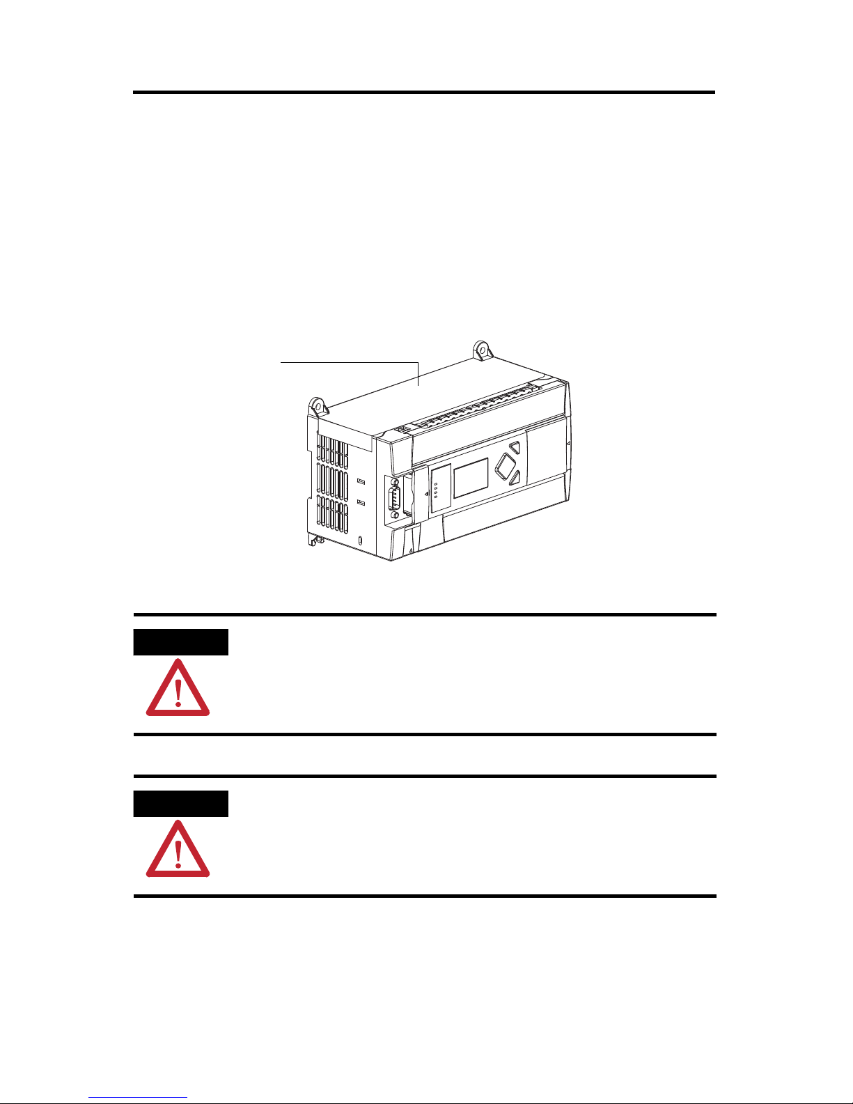
Debris strip
44513
Overview
MicroLogix 1400 controllers are suitable for use in an industrial environment when installed
in accordance with these instructions. Specifically, this equipment is intended for use in clean,
dry environments (Pollution degree 2
Category II
(2)
(IEC 60664-1)
(3)
an isolating transformer.
Install your controller using these installation instructions.
(1)
) and with circuits not exceeding Over Voltage
. AC powered products must be connected to the secondary of
Do not remove the protective debris strip until after the controller and all other
equipment in the panel near the controller are mounted and wiring is complete.
Once wiring is complete, remove protective debris strip. Failure to remove strip
before operating can cause overheating.
Electrostatic discharge can damage semiconductor devices inside the controller.
Do not touch the connector pins or other sensitive areas.
(1)
Pollution Degree 2 is an environment where, normally, only non-conductive pollution occurs except that occasionally a
temporary conductivity caused by condensation shall be expected.
(2)
Over Voltage Category II is the load level section of the electrical distribution system. At this level transient voltages are
controlled and do not exceed the impulse voltage capability of the product's insulation.
(3)
Pollution Degree 2 and Over Voltage Category II are International Electrotechnical commissions (IEC) designations.
Publication 1766-IN001D-EN-P - June 2015
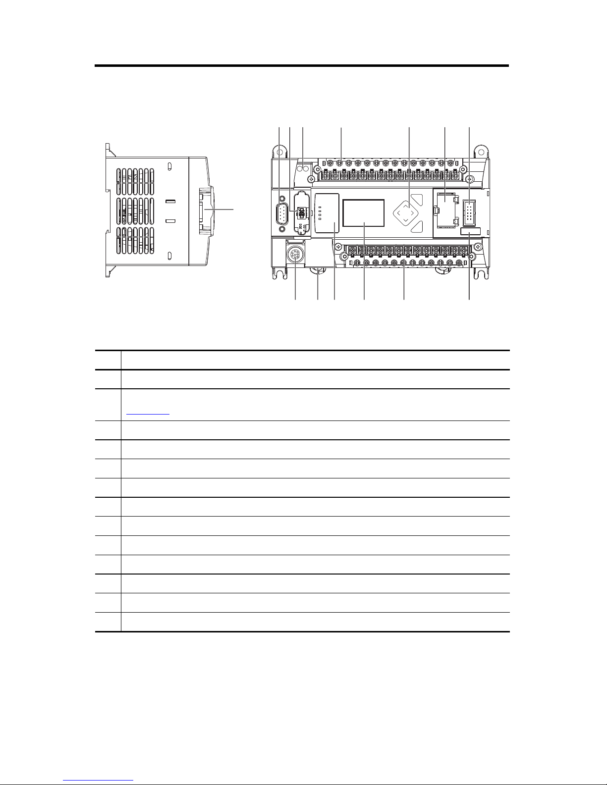
Controller Description
1
ESC
OK
256 7
8
9101113 12
43
1
44515
44514
Left side view Top view
MicroLogix 1400 Programmable Controllers 7
Description
1 Comm port 2 - 9-pin D-Shell RS-232C connector
2 Memory module (refer to MicroLogix 1400 Memory Module Installation Instructions, publication
1766-IN010
for instructions on installing the memory module).
3 User 24V (for 1766-L32BWA and 1766-L32BWAA only)
4 Input terminal block
5 LCD Display Keypad (ESC, OK, Up, Down, Left, Right)
6 Battery compartment
7 1762 expansion bus connector
8 Battery connector
9 Output terminal block
10 LCD Display
11 Indicator LED panel
12 Comm port 1 - RJ45 connector
13 Comm port 0 - 8-pin mini DIN RS-232C/RS-485 connector
Publication 1766-IN001D-EN-P - June 2015
8 MicroLogix 1400 Programmable Controllers
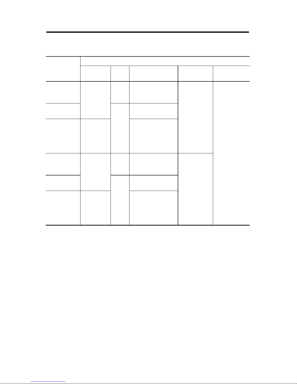
Controller Input and Output Description
Catalog
Number
Description
Input
Power
1766-L32BWA
100/240V AC
1766-L32AWA
1766-L32BXB 24 V DC
1766-L32BWAA
100/240V AC
1766-L32AWAA
1766-L32BXBA 24V DC
User
Power
24V DC
None
24V DC
None
Embedded
Discrete I/O
12 Fast 24V DC Inputs
8 Normal 24V DC Inputs
12 Relay Outputs
20 120V AC Inputs
12 Relay Outputs
12 Fast 24V DC Inputs
8 Normal 24V DC Inputs
6 Relay Outputs
3 Fast DC Outputs
3 Normal DC Outputs
12 Fast 24V DC Inputs
8 Normal 24V DC Inputs
12 Relay Outputs
20 120V AC Inputs
12 Relay Outputs
12 Fast 24V DC Inputs
8 Normal 24V DC Inputs
6 Relay Outputs
3 Fast DC Outputs
3 Normal DC Outputs
Embedded
Analog I/O
None
4 Voltage Inputs
2 Voltage
Outputs
Comm.
Ports
1 RS232/RS485
1 Ethernet/IP
1 RS232
(2)
(1)
(1)
Isolated RS-232/RS-485 combo port. Same as ML1100 Comm 0
(2)
Non-isolated RS-232. Standard D-sub connector
Publication 1766-IN001D-EN-P - June 2015
MicroLogix 1400 Programmable Controllers 9
WARNING
Hazardous Location Considerations
This equipment is suitable for use in Class I, Division 2, Groups A, B, C, D or non-hazardous
locations only. The following WARNING statement applies to use in hazardous locations.
EXPLOSION HAZARD
• Substitution of components may impair suitability for Class I, Division 2.
·
• Do not replace components or disconnect equipment unless power has been switched
off.
• Do not connect or disconnect components unless power has been switched off.
• This product must be installed in an enclosure. All cables connected to the product
must remain in the enclosure or be protected by conduit or other means.
• All wiring must comply with N.E.C. article 501-10(b) and/or in accordance with
Section 18-1J2 of the Canadian Electrical Code, and in accordance with the authority
having jurisdiction.
• For applicable equipment (for example, relay modules), exposure to some chemicals
may degrade the sealing properties of the materials used in these devices:
– Relays, epoxy
It is recommended that you periodically inspect these devices for any degradation of
properties and replace the module if degradation is found.
Use only the following communication cables in Class I, Division 2 hazardous locations.
Environment Classification Communication Cables
Class I, Division 2 Hazardous Environment 1761-CBL-AC00 Series C or later
1761-CBL-AM00 Series C or later
1761-CBL-AP00 Series C or later
1761-CBL-PM02 Series C or later
1761-CBL-HM02 Series C or later
2707-NC9 Series C or later
1763-NC01 Series A or later
1747-CP3 Series
Publication 1766-IN001D-EN-P - June 2015
10 MicroLogix 1400 Programmable Controllers
WARNING
ATTENTION
Environnements dangereux
Cet équipement est conçu pour une utilisation en environnements dangereux de Classe I,
Division 2, Groupes A, B, C, D ou non dangereux. La mise en garde suivante s’applique à
utilisation en environnements dangereux.
DANGER D’EXPLOSION
• La substitution de composants peut rendre cet équipement impropre à une utilisation
en environnement de Classe I, Division 2.
·
• Ne pas remplacer de composants ou déconnecter l’équipement sans s’être assuré que
l’alimentation est coupée.
• Ne pas connecter ou déconnecter des composants sans s’être assuré que
l’alimentation est coupée.
• Ce produit doit être installé dans une armoire. Tous les câbles connectés à l’appareil
doivent rester dans l’armoire ou être protégés par une goulotte ou tout autre moyen.
• L’ensemble du câblage doit être conforme à la réglementation en vigueur dans les
pays où l’appareil est installé.
Utilisez uniquement les câbles de communication suivants dans les environnements
dangereux de Classe I, Division 2.
Classification des environnements Câbles de communication
Environnement dangereux de Classe I, Division 2 1761-CBL-AC00 série C ou ultérieure
1761-CBL-AM00 série C ou ultérieure
1761-CBL-AP00 série C ou ultérieure
1761-CBL-PM02 série C ou ultérieure
1761-CBL-HM02 série C ou ultérieure
2707-NC9 série C ou ultérieure
1763-NC01 série A ou ultérieure
série 1747-CP3
UNSUPPORTED CONNECTION
Do not connect the Comm0 port on the MicroLogix 1400 controller to another MicroLogix
family controller such as MicroLogix 1000, MicroLogix 1200, or MicroLogix 1500 using a
1761-CBL-AM00 (8-pin mini-DIN to 8-pin mini-DIN) cable or equivalent.
This type of connection will cause damage to the RS-232/485 communication port
(Channel 0) of the MicroLogix 1400 and/or the controller itself. Communication pins used
for RS-485 communications are alternately used for 24V power on the other MicroLogix
controllers.
Publication 1766-IN001D-EN-P - June 2015
MicroLogix 1400 Programmable Controllers 11
ATTENTION
ATTENTION
WARNING
WARNING
Mount the Controller
General Considerations
Most applications require installation in an industrial enclosure to reduce the effects of
electrical interference and environmental exposure. Locate your controller as far as possible
from power lines, load lines, and other sources of electrical noise such as hard-contact
switches, relays, and ac motor drives. For more information on proper grounding guidelines,
see the Industrial Automation Wiring and Grounding Guidelines, publication 1770-4.1
Mount the controller horizontally only. Vertical mounting is not supported due to
thermal considerations.
.
Be careful of metal chips when drilling mounting holes for your controller or
other equipment within the enclosure or panel. Drilled fragments that fall into
the controller could cause damage. Do not drill holes above a mounted controller
if the protective debris strips have been removed.
Do not place the MicroLogix 1400 Programmable Controller in direct sunlight.
Prolonged exposure to direct sunlight could degrade the LCD display.
·
The local programming terminal port is intended for temporary use only and
must not be connected or disconnected unless the area is assured to be
nonhazardous.
·
Publication 1766-IN001D-EN-P - June 2015
12 MicroLogix 1400 Programmable Controllers
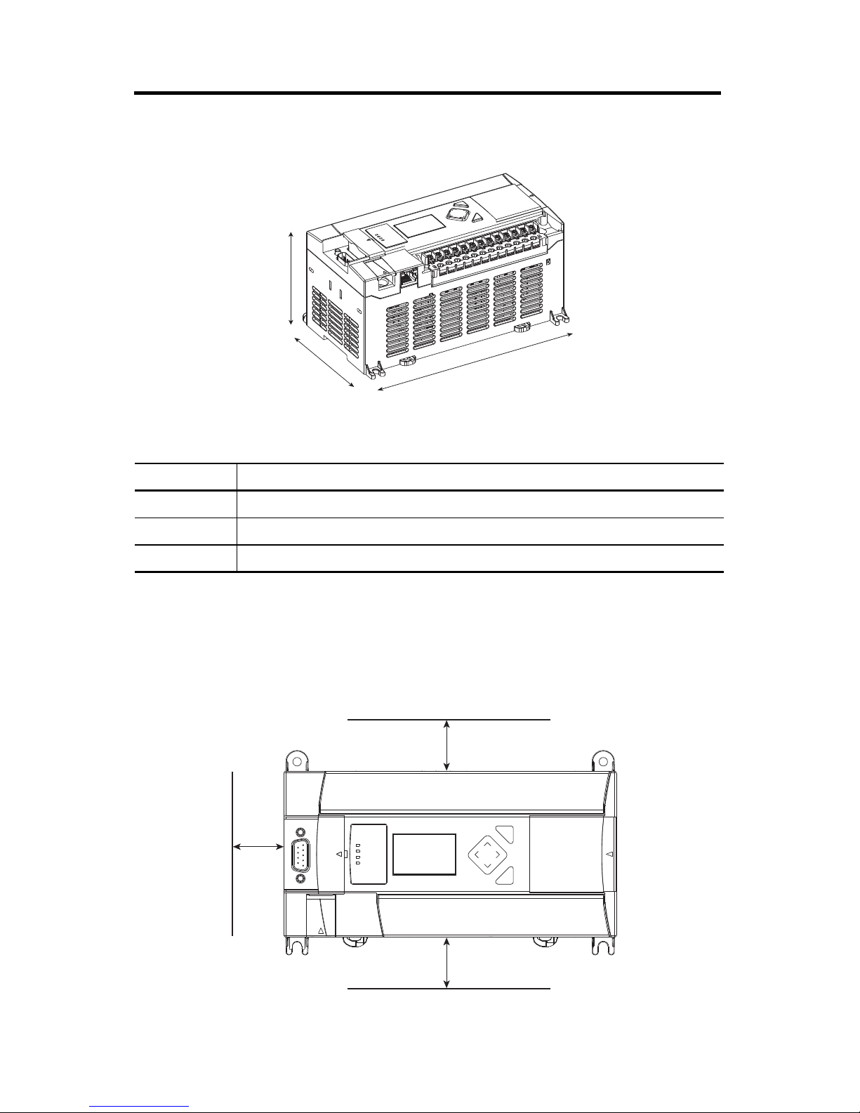
C
B
A
1766-L32BWA, 1766-L32AWA, 1766-L32BXB,
1766-L32BWAA, 1766-L32AWAA, 1766-L32BXBA
44516
ESC
OK
Top
Bottom
Side
44517
Mounting Dimensions
Dimension Height
A 90 mm (3.5 in.)
B 180 mm (7.087 in.)
C 87 mm (3.43 in.)
Controller Spacing
The controller mounts horizontally, with the expansion I/O extending to the right of the
controller. Allow 50 mm (2 in.) of space on all but the right side for adequate ventilation, as
shown below.
Publication 1766-IN001D-EN-P - June 2015
MicroLogix 1400 Programmable Controllers 13
44518
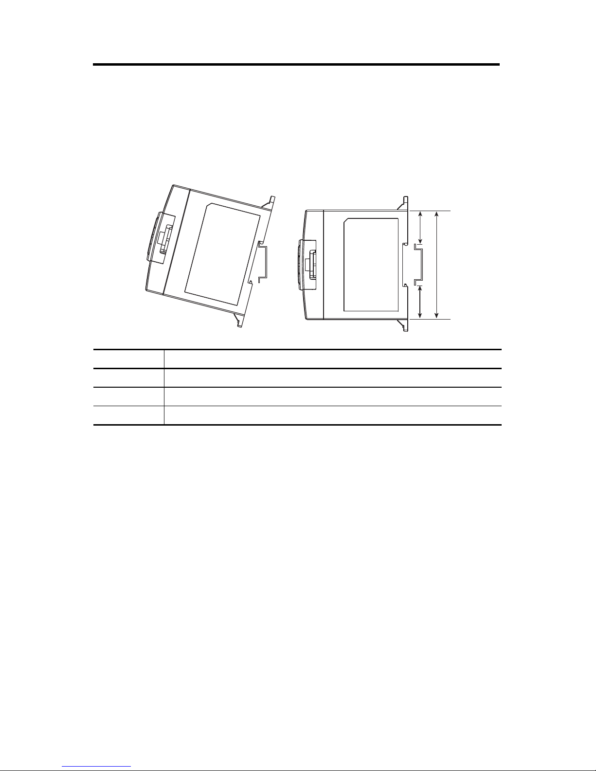
DIN Rail Mounting
The maximum extension of the latch is 14 mm (0.55 in.) in the open position. A flat-blade
screwdriver is required for removal of the controller. The controller can be mounted to
EN50022-35x7.5 or EN50022-35x15 DIN rails. DIN rail mounting dimensions are shown
below.
B
A
C
Dimension Height
A 90 mm (3.5 in.)
B 27.5 mm (1.08 in.)
C 27.5 mm (1.08 in.)
Follow these steps to install your controller on the DIN rail.
1. Mount your DIN rail. Make sure that the placement of the controller on the DIN rail
meets the recommended spacing requirements (see Controller Spacing on page 12 for
more information). Refer to the mounting template inside the back cover of this
document.
2. If it is open, close the DIN latch.
3. Hook the top slot over the DIN rail.
4. While pressing the controller down against the top of the rail, snap the bottom of the
controller into position.
5. Leave the protective debris strip attached until you are finished wiring the controller
and any other devices.
Publication 1766-IN001D-EN-P - June 2015
 Loading...