

Page 1

Pump Station Controller
Quick Start
Page 2
Important User Information
WARNING
IMPORTANT
ATTENTION
SHOCK HAZARD
BURN HAZARD
Solid state equipment has operational characteristics differing from those of electromechanical equipment. Safety Guidelines
for the Application, Installation and Maintenance of Solid State Controls (publication SGI-1.1
Automation sales office or online at http://www.rockwellautomation.com/literature/
between solid state equipment and hard-wired electromechanical devices. Because of this difference, and also because of the
wide variety of uses for solid state equipment, all persons responsible for applying this equipment must satisfy themselves that
each intended application of this equipment is acceptable.
In no event will Rockwell Automation, Inc. be responsible or liable for indirect or consequential damages resulting from the use
or application of this equipment.
The examples and diagrams in this manual are included solely for illustrative purposes. Because of the many variables and
requirements associated with any particular installation, Rockwell Automation, Inc. cannot assume responsibility or liability for
actual use based on the examples and diagrams.
No patent liability is assumed by Rockwell Automation, Inc. with respect to use of information, circuits, equipment, or software
described in this manual.
Reproduction of the contents of this manual, in whole or in part, without written permission of Rockwell Automation, Inc., is
prohibited.
Throughout this manual, when necessary, we use notes to make you aware of safety considerations.
available from your local Rockwell
) describes some important differences
Identifies information about practices or circumstances that can cause an explosion in a hazardous environment,
which may lead to personal injury or death, property damage, or economic loss.
Identifies information that is critical for successful application and understanding of the product.
Identifies information about practices or circumstances that can lead to personal injury or death, property damage,
or economic loss. Attentions help you identify a hazard, avoid a hazard, and recognize the consequence
Labels may be on or inside the equipment, for example, a drive or motor, to alert people that dangerous voltage may
be present.
Labels may be on or inside the equipment, for example, a drive or motor, to alert people that surfaces may reach
dangerous temperatures.
Allen-Bradley, Rockwell Automation, and TechConnect are trademarks of Rockwell Automation, Inc.
Trademarks not belonging to Rockwell Automation are property of their respective companies.
Page 3

Table of Contents
Preface
Configuration and Operation
Drawing Set
Table of Contents
Introduction . . . . . . . . . . . . . . . . . . . . . . . . . . . . . . . . . . . . . . . . . . . . . . . 3
Chapter 1
Pump Station Controller . . . . . . . . . . . . . . . . . . . . . . . . . . . . . . . . . . . . . 5
Chapter 2
Pump Station Controller Hardware Drawings . . . . . . . . . . . . . . . . . . . 41
1Publication IASIMP-QS037A-EN-P - May 2013 2013 1
Page 4

2 Publication IASIMP-QS037A-EN-P - May 2013 2013
Page 5

Preface
Introduction
This Quick Start Guide contains step-by-step instructions for configurating
and operating the Pump Station Controller. The Controller consists of a
standard pre-engineered package using off-the-shelf products including the
MicroLogix 1400 PLC, PanelView Component C600 HMI and PowerFlex
drives. Application files are also supplied so no PLC programming is required
and HMI screens are pre-programmed.
This package includes the PLC and HMI application code plus a full set of
system, panel, and electrical drawings that includes a bill of material. You can
download the application code and drawings by going to the Rockwell
Automation Integrated Architecture Tools Website,
http://www.ab.com/go/iatools
tab. The Pump Station Controller application download can be found on this
page.
and selecting the “Beyond Getting Started”
3Publication IASIMP-QS037A-EN-P - May 2013 3
Page 6

Preface
Notes:
4 Publication IASIMP-QS037A-EN-P - May 2013
Page 7

Configuration and Operation
Chapter
1
Pump Station Controller
Introduction
This application uses the MicroLogix 1400 and PanelView Component C600
to provide a "stand alone" multifunction pump controller that allows the user
the ability to choose between a pump down (lift station), pump up (water
tank), or a pressure follower (water distribution) control process, with just a
few simple screen selections.
Functionality includes:
● Control of up to 4 pumps.
● User assignable inputs.
● Use of floats, analog or a combination of both to control the process.
● Control of VFDs through Modbus communication, which reduces the
control wiring to the drives (PowerFlex 4/40/400 VFDs only)
● Pump control can be done with starters, PowerFlex 4 series VFDs or
with another manufactures VFD.
● Pump sequencing control.
● User selectable alarms with the ability to choose which ones can be used
to initiate an alarm dialer (user supplied)
● Pump statistics.
● The ability to save and load VFD parameters from the HMI. (PF4
VFDs only).
● Selectable pump interlocks.
● Screen access security.
5Publication IASIMP-QS037A-EN-P - May 2013 5
Page 8
Chapter 1
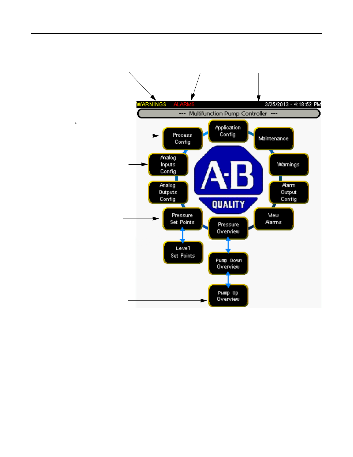
Flashes when a Warning exists
Flashes when an Alarm exists Common header
Not visible until an application has been selected
Only visible if analog device is being used
Legend depends on if Pressure Follower,
Level Pump Down or Level Pump Up mode is selected
Legend depends on if Pressure Follower”
mode is selected or Level mode is selectd
Main Screen
The main screen displays configuration, monitoring and maintenance controls.
Some control label content displays based on the current configuration.
Several of the buttons on the Main screen do not display until the application
has been set up. So the first step is to go through the Application Config
button.
6 Publication IASIMP-QS037A-EN-P - May 2013
Page 9
Chapter 1
Configuring the Application
The functions available when you select the Application Config button
include:
● Select the pumps and pump modes
● Select primary and secondary measuring devices
● Select control devices for all active pumps
● Assign digital inputs and their states
● Assign backup pumps
Each of the configuration screens contains standard navigational tools:
● Press Prev or Next to navigate between screens.
● Press Up, Down, or Enter to navigate available choices on a single
screen.
● Press Exit to return to the Main menu.
To use the configuration controls:
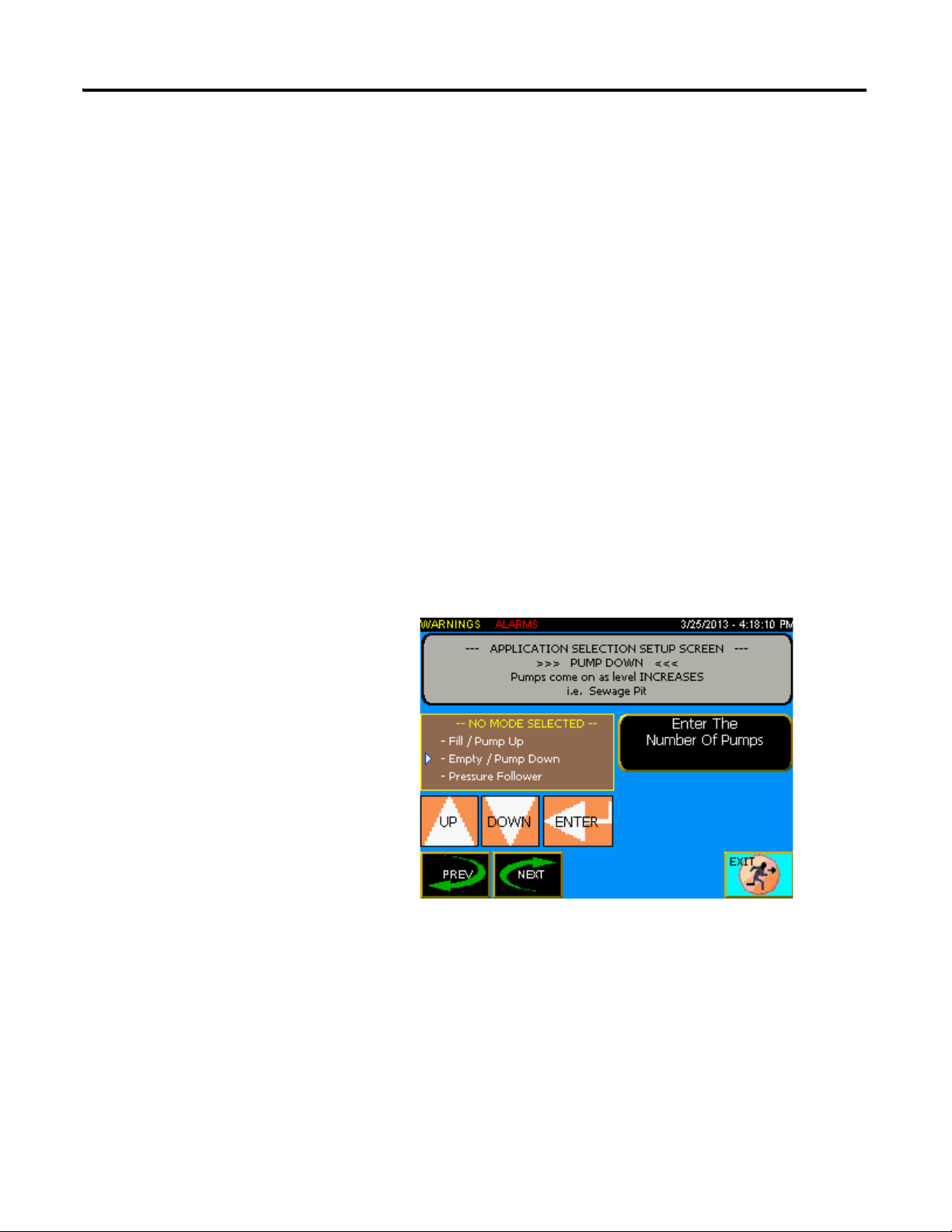
1. From the Main screen, press Application Config to display the
configuration screen.
From the configuration screen you can:
– Use the Up/Down/Enter buttons to select from the three available
operation modes
– Press Enter The Number Of Pumps to select the number of
pumps (1-4) in use in the system
– View a description of the selected mode
Publication IASIMP-QS037A-EN-P - May 2013 7
Page 10
Chapter 1
TIP
TIP
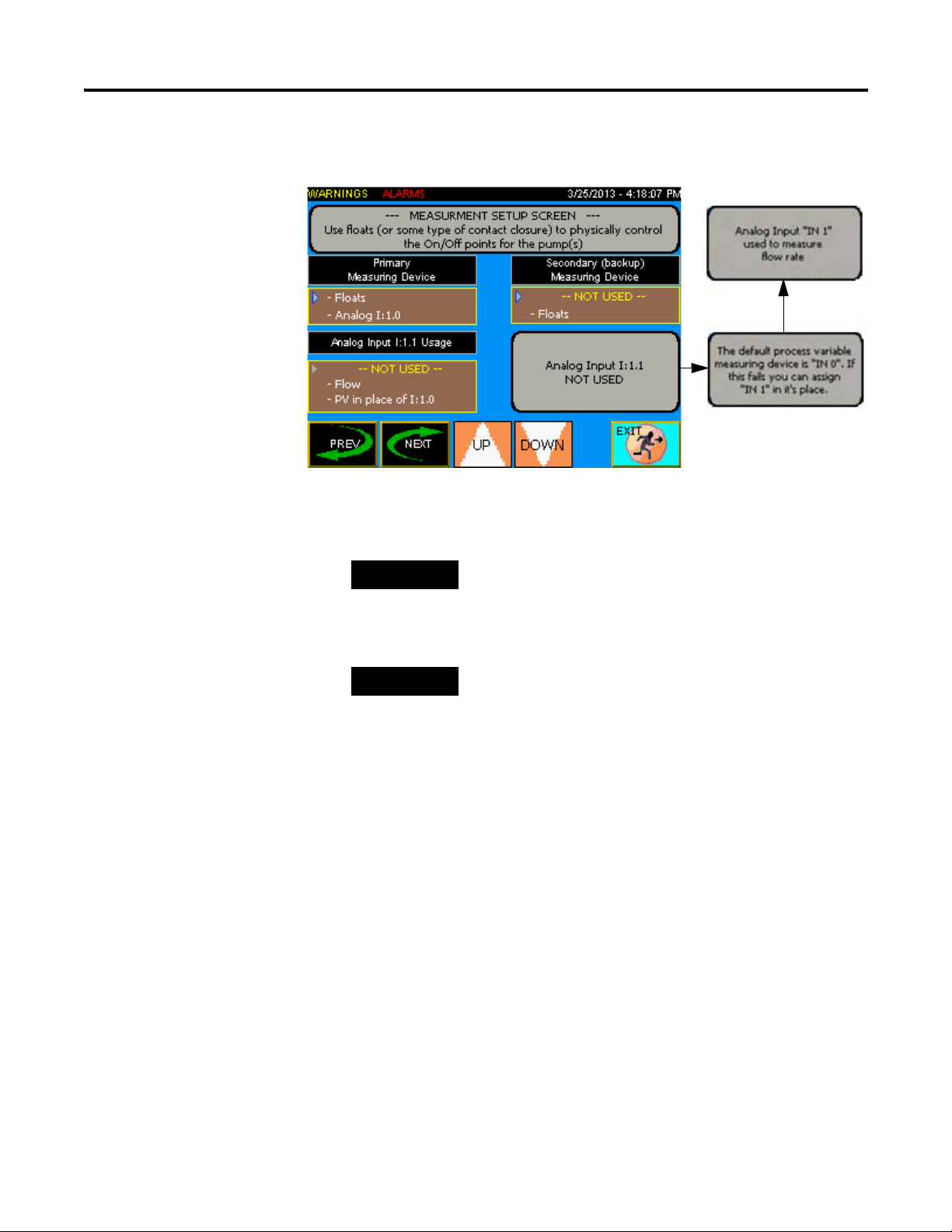
2. Press Next to proceed to the Measuring Setup screen.
From the Measuring Setup screen you can:
– Use the Up/Down buttons to select the primary measuring device.
If Pressure Follower mode is selected then Analog "In 0" is the only option for
the primary measuring device.
– Select a secondary measuring device
If the primary measuring device is an analog device, you can assign a float to be
used as backup (not available if primary measuring is floats).
– Use the second analog input (IN 1) to measure flow rate from an
analog transmitter or as the process variable if the default analog
input (IN 0) fails.
When analog input "IN 1" (I:1.1) is set for Flow the flow is totalized
using a calculation in the PLC. A more accurate way to totalize would
be to use digital input I:0/0 as a totalized pulse.
8 Publication IASIMP-QS037A-EN-P - May 2013
Page 11
Chapter 1
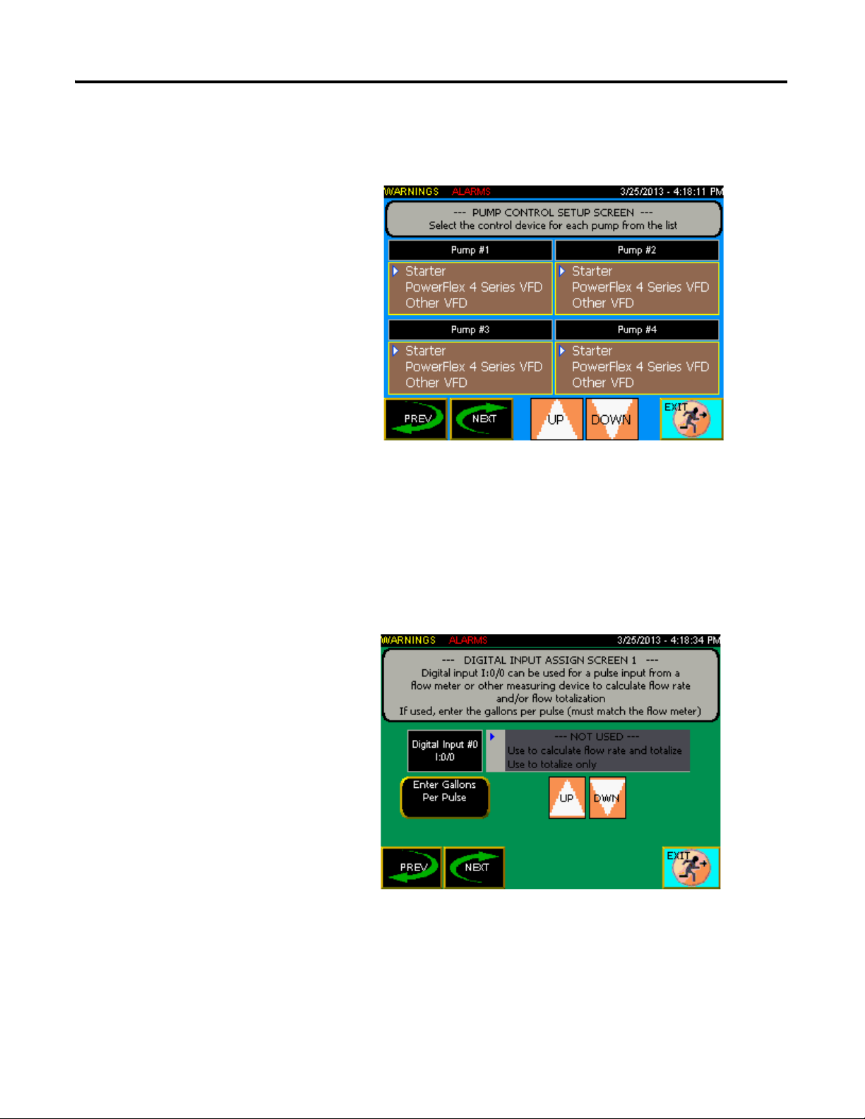
3. Press Next to proceed to the Motor Control Setup screen. In the
example shown, four pumps have been configured; the screen will only
display as many pumps as you set up in the initial configuration screen.
From the Motor Control Setup screen you can use the Up/Down
buttons to select the pump control device.
The Starter and Other VFD selections use physical outputs from the
PLC to control the start/stop operation of the motors, while the
PowerFlex 4 option uses Modbus communication to control the VFD.
4. Press Next to proceed to the first Digital Inputs Assign screen. There
are four Digital Inputs Assign screens in total.
From the first Digital Inputs Assign screen you can:
– Use Digital input I:0/0 as a pulsed input to totalize flow only or to
totalize flow and calculate a flow rate.
Publication IASIMP-QS037A-EN-P - May 2013 9
Page 12
Chapter 1
As a flow totalizer this can be very accurate. However, using it to
calculate flow rate is not as accurate as using analog input I:1.1 as a
flow rate input.
– Press Enter Gallons Per Pulse to set the appropriate gallons per
input pulse
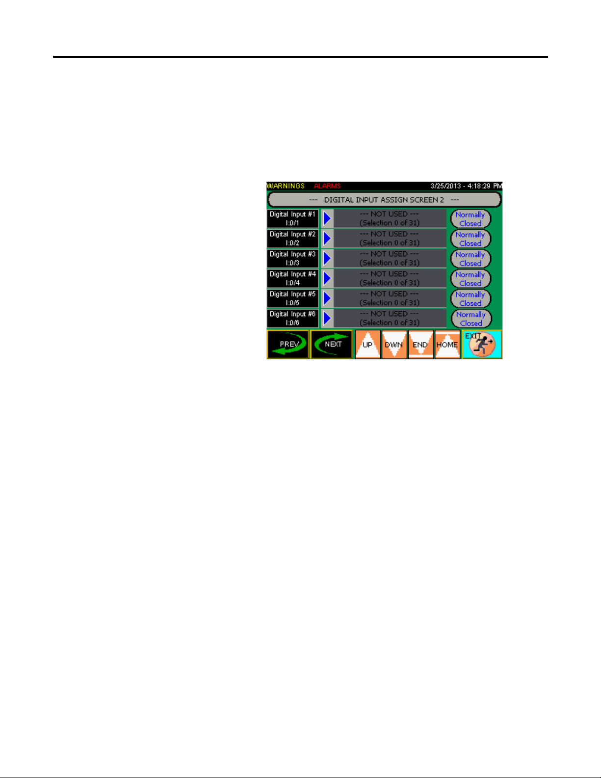
5. Press Next to proceed to the next Digital Inputs Assign screen.
From the remaining Digital Inputs Assign screens you can:
– Press Normally Open or Normally Closed to set the state to
match the way the digital input is wired on the field device.
– Use the Up/Down and End/Home buttons to scroll through the
list of selections
– Digital inputs I:0/0 – I:0/17 are assignable to any of the 31
selections listed; however, depending on the application, they may
not all be applicable. For example, if you only have two pumps in
your system, selection #20 Pump 3 seal fail would not apply
10 Publication IASIMP-QS037A-EN-P - May 2013
Page 13

Chapter 1
NOT USED --(Selection 0 of 31)
Low Level
(Selection 1 of 31)
Pumps Stop
(Selection 2 of 31)
Lead Start
(Selection 3 of 31)
Lag Start
(Selection 4 of 31)
High Level
Selection 5 of 31)
Pump 1 Running
(Selection 6 of 31)
Pump 2 Running
(Selection 7 of 31)
Pump 3 Running
(Selection 8 of 31)
Pump 4 Running
(Selection 9 of 31)
Pump 2 OL/Fault
(Selection 11 of 31)
Pump 3 OL/Fault
(Selection 12 of 31)
Pump 4 OL/Fault
(Selection 13 of 31)
Pump 1 Motor Over Temp
(Selection 14 of 31)
Pump 2 Motor Over Temp
(Selection 15 of 31)
Pump 3 Motor Over Temp
(Selection 16 of 31)
Pump 4 Motor Over Temp
(Selection 17 of 31)
Pump 1 Seal Fail
(Selection 18 of 31)
Pump 2 Seal Fail
(Selection 19 of 31)
Pump 3 Seal Fail
(Selection 20 of 31)
Low Pressure
(Selection 22 of 31)
High Pressure
(Selection 23 of 31)
Power failure
(Selection 24 of 31)
Generator Running
(Selection 25 of 31)
Generator Fault
(Selection 26 of 31)
General Fault
(Selection 27 of 31)
Pump #1 Auto
(Selection 28 of 31)
Pump #2 Auto
(Selection 29 of 31)
Pump #3 Auto
(Selection 30 of 31)
Pump #4 Auto
(Selection 31 of 31)
Pump 1 OL/Fault
(Selection 10 of 31)
Pump 4 Seal Fail
(Selection 21 of 31)
Publication IASIMP-QS037A-EN-P - May 2013 11
Page 14
Chapter 1
TIP
TIP
TIP
If during the measuring
buttons will enable or
device setup, floats are
selected as secondary
(backup) then these
disable the pumps from
running in backup mode.
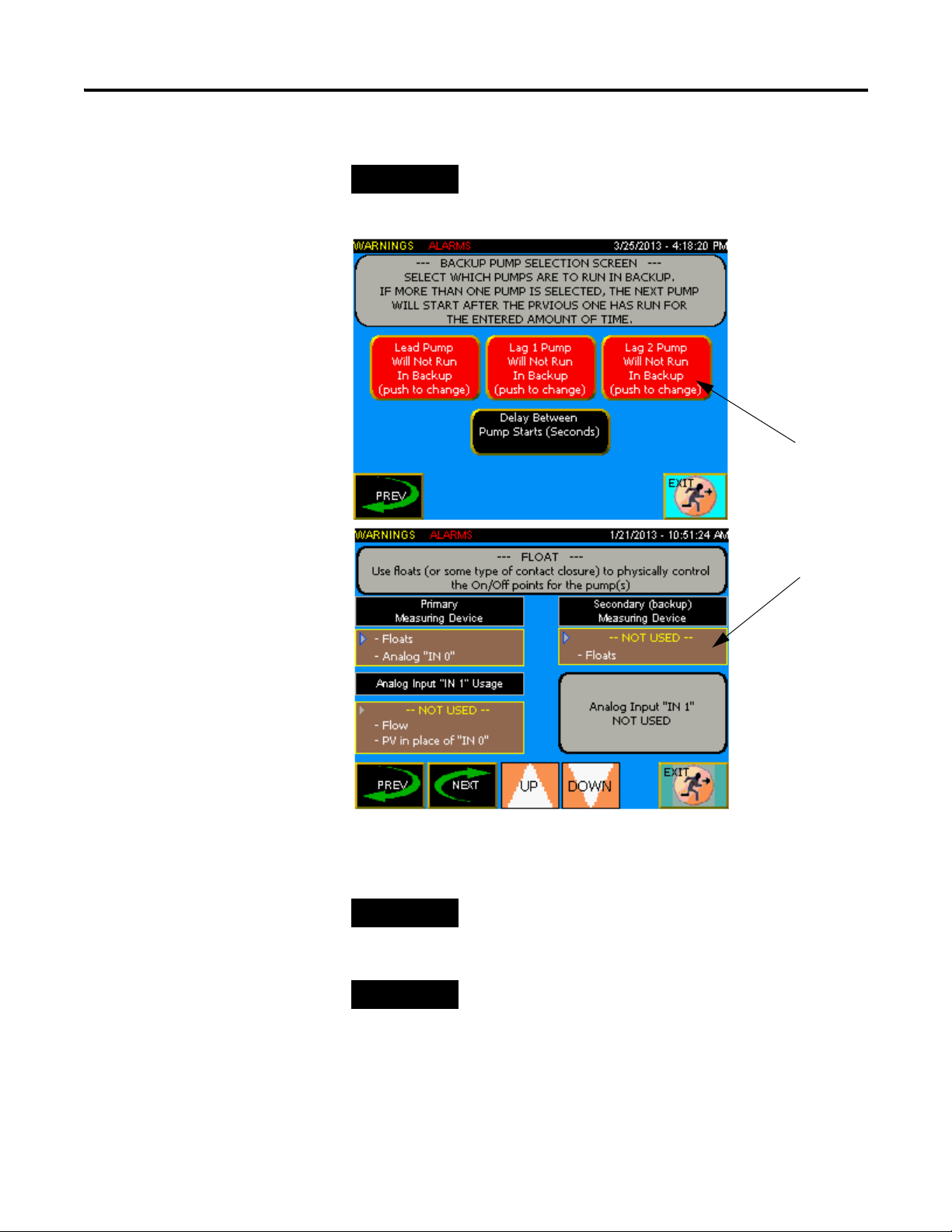
– Press Next to proceed to the Backup Pump Select screen.
The Backup Pump Selection screen is visible only if Float is selected as the
backup on the Measuring Setup screen.
Press the Delay Between Pump Starts (Seconds) to enter the delay
before the next one starts when more than one backup pump is enabled.
If on the “Measuring Setup” screen (above) the “Secondary (backup) Measuring
Device” is set to “NOT USED”, then no pumps will run in backup.
If on the “Measuring Setup” screen (above) the “Secondary (backup) Measuring
Device” is set to “Floats”, then backup pumps will start when the “Lead Start”
float is activated, and continue until the “Pumps Stop” float is activated.
A “lead start” and a “pumps stop” selection must be assigned to an input on
one of the “Digital Input Assign” screens.
12 Publication IASIMP-QS037A-EN-P - May 2013
Page 15
Chapter 1
Because this is a backup operation likely due to a failure, the pumps do not
alternate.
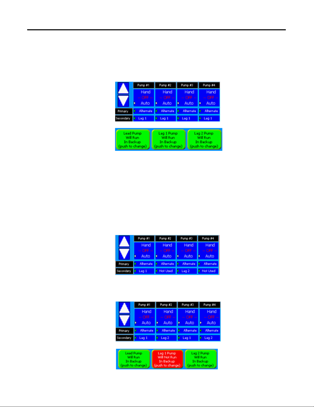
Setup Examples
Example 1: In a pump
down application. Floats
are being used as backup.
On the Pump Sequence
Setup screen, the Primary
selection for all pumps is
set to Alternate, and the
Secondary selections are
set to Lag1. And on the
Backup Pump Selection
screen, lead, lag1 and lag2
pumps are all allowed to
run as backup. As the level rises and activates the Lead Start float. The lead
pump (because all are set for alternate, it could be any of the four pumps)
starts. Let’s say that the Delay Between Pump Starts (see graphic above) is
set for 60 sec. If the Pumps Stop float does not clear in this time, all of the
pumps assigned to Lag1 as Secondary will start (in this case all of them). If a
pump was set to Lag2 as the Secondary selection, it will start 60 sec. after the
Lag1 pump(s) start. If all of the pumps are set to Lag2 as Secondary, then no
pumps will start during the first 60 sec. (Lag1 time). The sequence is: lead
pump --- delay --- lag1 pump(s) --- delay --- lag2 pump(s). Once a pump starts,
it will continue to run until the Pumps Stop float clears.
Example 2: Same setup as
above except the
Secondary selections are
now as shown. Let’s say that
pump 2 is the lead pump.
Lead Start float is activated.
Pump 2 starts --- 60 sec.
time delay --- pump 1 (lag1) starts --- 60 sec. time delay --- pump 3 (lag2) starts.
Because pump 4 is set to Not Used it does not run.
Example 3: The setup is as
shown, however now the
Lag1 pump is not allowed
to run in backup. Again,
let’s say that pump 2 is the
lead pump. Lead Start float
is activated. Pump 2 starts
--- 60 sec. time delay --- and
although pumps 1 and 3 are
both set for lag1, they do no
Publication IASIMP-QS037A-EN-P - May 2013 13
Page 16
Chapter 1
IMPORTANT
run because the lag1 pumps are not allowed to run due to the selection on the
Backup Pump Selection screen --- 60 sec. time delay --- pump 4 (lag2) starts.
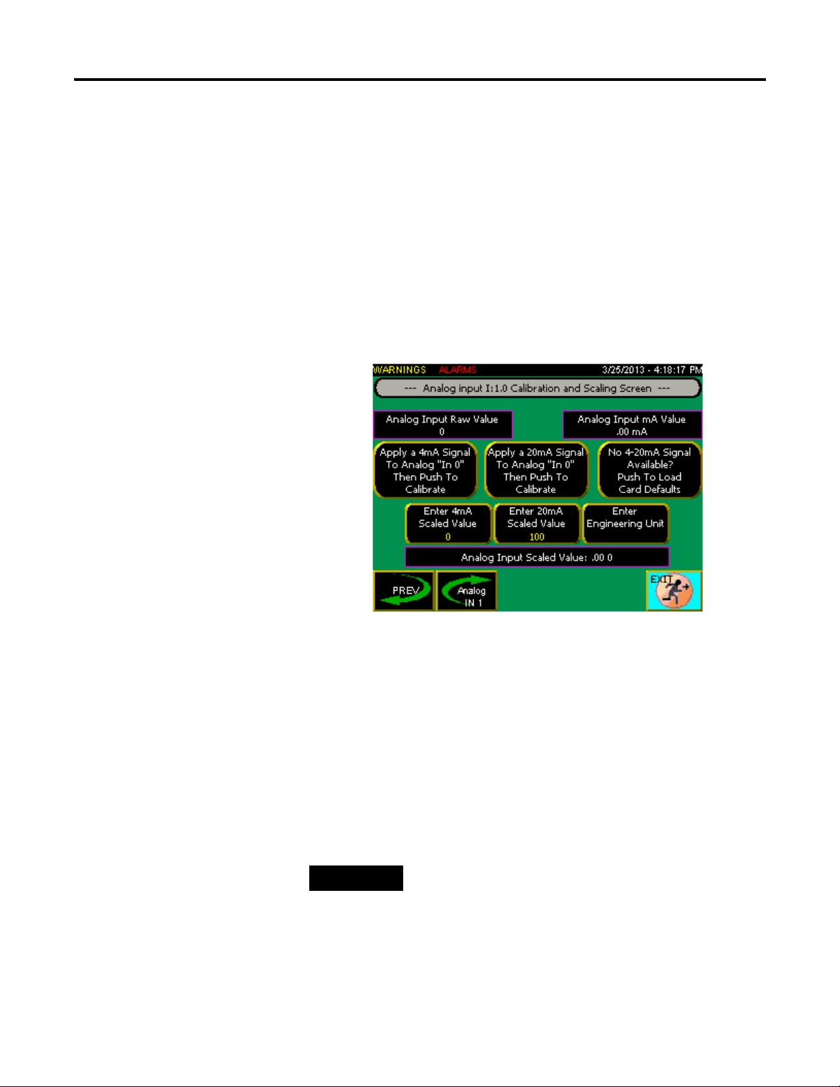
Configuring Analog Inputs
Now that the application has been set up, you can continue through the rest of
the configuration.
1. From the Main screen, press Analog Inputs Config to display the
configuration screen.
This button is not visible unless an analog device is being used
(Measurement Setup screen).
The screen includes displays showing the raw data coming from the
analog input card and mA value of the input from the calibrated (zero
and span set) card.
2. Select one of the two following calibration methods:
– Apply a 4mA signal to the cards input (I:1.0), then push Apply a
4mA Signal To Analog "In 0" to make the zero adjustment. After
making the zero adjustment, choose Apply a 20mA Signal To
Analog "In 0" to make the span adjustment if a signal is available.
– Select No 4-20mA Signal Available? to calibrate the analog input
using the card's default values if no current calibrator is available.
You must use one of these calibration methods to ensure proper operation.
3. Enter a scaled value in the Enter 4mA Signal Value field. For example:
0 Ft.
4. Enter a scaled value in the Enter 20mA Signal Value field. For
example: 10 Ft.
14 Publication IASIMP-QS037A-EN-P - May 2013
Page 17

Chapter 1
TIP
TIP
5. Enter a measurement unit type in the Enter Engineering Unit field.
For example: Ft, Inch, PSI.
6. Once the scaled values have been entered, the scaled value of the analog
input displays in the Analog Input Scaled Value area.
7. The second analog Input (I:1.1) is the same as input I:1.0. If the second
analog input is not being used, it does not need to be set up.
Configuring Analog Outputs
1. From the Main screen, press Analog Outputs Config to display the
configuration screen.
2. Set the Analog Output “Out 0” Usage (O:1.0) to retransmit a
4-20mA signal from the process variable (the analog signal connected to
one of the analog inputs) or to set the pump #1 VFD speed reference
(4mA=0Hz, 20mA=60Hz).
3. Set the Analog Output “Out 1” Usage (O:1.1) to retransmit a 4-20mA
signal from the process variable (the analog signal connected to one of
the analog inputs) or to set the pump #2 VFD speed reference
(4mA=0Hz, 20mA=60Hz).
Note: The process variable can be the signal from analog input I:1.0 or input I:1.1.
The default process variable is I:1.0 but can be changed from the Measuring
Setup screen under the Analog Input “In 1” Usage selection.
Note: In order for the analog output to transmit a VFD speed reference, the
corresponding pump needs to have either PowerFlex 4 series VFD or Other
VFD selected from the Motor Control Setup screen.
Publication IASIMP-QS037A-EN-P - May 2013 15
Page 18

Chapter 1
Setting the Process Configuration
1. From the Main screen, press Process Config to display the setup
screen. The number of pumps shown may vary depending on how many
pumps are in use.
2. From the setup screen you can:
– Use the UP/DOWN buttons to select between Hand, Off and
Auto for each configured pump.
– Set a Primary selection for each pump. Select from Alternate, Lead,
Lag 1 and Lag 2.
– Set a Secondary selection for each pump. Select from Lag 1, Lag 2
and Not Used.
The secondary selections only come into use when the primary
selection is set as Alternate and a second pump is required to run.
The following are three examples of sequencing:
1. Pumping sequence example #1: All pumps have “Alternate” selected
as primary and are in “Auto”. When a pump is required to run, pump
#1 starts and runs until the level is satisfied. The next time a pump is
required to run, pump #2 starts; however the level gets to a point
where one pump cannot keep up and a second pump is required. At
that point all of the pumps with “Lag 1” selected as secondary will
start. All pumps will continue to run until the level is satisfied.
2. Pumping sequence example #2: Same scenario as example #1 except
pump #2 is “Off ”. After pump #1 runs and then turns off. Pump
#3 will run on the next cycle. Because even though pump #2 has
“alternate” selected, it is turned “Off ” and is therefore taken out of
the alternation sequence.
16 Publication IASIMP-QS037A-EN-P - May 2013
Page 19

Chapter 1
3. Pumping sequence example #3: Pump #2 is set for “Lead”, pump
#1 is set for “Lag 1” and pump #3 is set for “Lag2”. When the level
requires a pump to r un, pump #2 comes on and runs until the level is
satisfied. If the level continues to change and requires another pump
to run, pump #1 will start. If the level still continues to change and
requires another pump, pump #3 will start. The pumps will continue
to run until the stop level is satisfied. With all pumps now off, when
the level requires a pump to come on, the sequence repeats itself,
there is no alternation.
4. Access other setup screens as needed from the navigation at the bottom
of the Process Config screen.
– Press Pump Interlocks to open the Pump Interlocks screen. Refer
to Pump Interlocks on page 17.
– Press Backup Pump Selection to open the Backup Pump Selection
screen. Visible only if Float is selected as backup on the Measuring
Setup screen. Refer to page 12.
– Press Pressure Setpoints to open the Pressure Setpoints screen
Visible only if Pressure follower mode is selected. Refer to Pressure
Setpoints on page 19.
– Press Level Setpoints to open the Level Setpoints screen. Visible
only if an analog device is being used for measuring level. Refer
to Level Setpoints on page 18.
Pump Interlocks
You can use the Pump Interlocks screen to select from a list of faults that will
inhibit the pump from running.
1. Select and perform the following steps for each pump individually.
Publication IASIMP-QS037A-EN-P - May 2013 17
Page 20

Chapter 1
20mA Scaled value
4mA Scaled value
Current level
scaled value
2. Select the interlock from the list, and then use the Add Interlock
button to add it to the Current Interlocks or use the Remove Interlock
button to remove it from the Current Interlocks.
For example: If Pump Seal Fail is in an alarm state, press Remove
Interlock to allow the pump to continue running in that alarm state.
A white X in a red circle indicates an interlock that has been removed,
while a blue check mark in a gray box indicates an interlock that has
been added.
Level Setpoints
18 Publication IASIMP-QS037A-EN-P - May 2013
From the Level Setpoints screen you can:
– Press On Setpoint to enter the level at which you want the selected
pump to turn on.
– Press Off Setpoint to enter the level at which you want the selected
pump to turn off.
– Press VFD # Speed Hz to enter the desired VFD speed (in Hz)
when running in Level mode. The VFD # Speed Hz button is not
visible if Starters were selected on the Motor Control Setup screen.
– Press the High and Low Alarm Setpoints to enter the threshold
values for triggering the related alarms.
Page 21

Pressure Setpoints
From the first Pressure Setpoints screen you can:
– Press Pressure Setpoint to enter the desired system pressure.
– Press Start Pressure to set the pressure (combined with the time
delay) at which the Lag 1 and Lag 2 pumps will come on if the
desired pressure is unable to be maintained.
– View the current pressure reading (analog input must have been set
up previously).
– Press Once Below Start Pressure The Next Pump Will Start in:
(Seconds) to enter the time delay in seconds between Lag pump
starts. If system pressure falls below the start set point, the Lag pump
starting is delayed by this value.
– Press Off Pressure to set the system pressure point at which all of
the pumps shut off.
– Press More to see the second Pressure Setpoints screen.
Chapter 1
Publication IASIMP-QS037A-EN-P - May 2013 19
Page 22

Chapter 1
TIP
TIP
– Press VFD # Manual Speed Hz to set the speed at which the drive
will run when placed into Manual.
– Press Enter The Alternation Time In Minutes to set the time
between pump alternations. This is only used if the Primary
selection is set to Alternation on the Process Configuration
screen.
Lead pump alternation will only occur if the lead pump is the only pump running.
If the alternation time has elapsed during high demand when more pumps are
running, the alternation will happen only when all pumps other than the lead
pump have turn off.
– Press High Setpoint to set the high pressure alarm threshold.
The High Pressure alarm set point is not the same as the All Pumps Off set
point on the Pressure Set point 1 screen. The All Pumps Off set point is meant
to turn the pumps off before it goes into High Pressure alarm.
– Press Low Setpoint to set the low pressure alarm threshold.
Pressure Overview Screen
From the Pressure Overview screen you can:
– View the current system pressure and set point
– View the flow rate readout, if Analog Input In 1 is assigned to Flow
on the Measuring Setup screen, or if Digital Input 0 (I:0/0) on the
Digital Inputs Assign 1 screen is set for Use For Pulse Counter
20 Publication IASIMP-QS037A-EN-P - May 2013
Page 23

– View pump status, mode and sequence information, as shown below
Auto selected
Pump
Off selected
Pump stopped
Pump run sequence set
Hand selected
Pump run sequence set to Lead
Pump run sequence set to Lag 1
to Alternate
Pump
Pump
Pump Down Overview Screen
Chapter 1
From the Pump Down Overview screen you can:
– View the 20mA scaled value
– View the current level scaled value
– View the 4mA scaled value
– View pump status, mode and sequence information, as on the
Pressure Overview screen.
Publication IASIMP-QS037A-EN-P - May 2013 21
Page 24

Chapter 1
Pump Up Overview Screen
From the Pump Up Overview screen you can view pump status, mode,
sequence and level information.
Maintenance Screen
From the Maintenance screen you can:
– The Secured Settings button is only accessible with "Admin" or
"Supervisor" access.
– Press VFD # Speed Hz to enter the desired speed for each VFD.
The VFD # Speed Hz button is visible only if PowerFlex 4 VFD
or Other VFD is selected in the Motor Control Setup screen.
– Press PowerFlex VFD Parameters to open the PowerFlex 4 VFD
Parameters screen. Refer to PowerFlex 4 VFD Parameters on
page 24. The PowerFlex VFD Parameters button is visible only if
PowerFlex 4 VFD is being used.
22 Publication IASIMP-QS037A-EN-P - May 2013
Page 25

– Press Pump Statistics to open the Pump Statistics screen. Refer
to Pump Statistics Screen on page 23. The Pump Statistics button is
only visible after an application has been assigned
– Press PID Tuning to access the PD Tuning screen. Refer to PID
Tuning Screen on page 24. The PID Tuning button is visible only if
Pressure Follower mode is selected
– Press PanelView Config to close the running PanelView application
and open the PanelView configuration screen
Pump Statistics Screen
Chapter 1
From the Pump Statistics screen you can:
– Select a pump to view the statistics for that pump. The number of
pumps visible depends on how many are in use. The flow totalization
is only visible if digital input I:0/0 is set to totalize or if analog input
I:1.1 is set for flow
– Reset the run time and cycle count (shown in yellow)
– View the motor current and voltage if a PowerFlex series 4 VFD is in
use
– View the flow totalization, if digital input I:0/0 is set to totalize or if
analog input I:1.1 is set for flow
Publication IASIMP-QS037A-EN-P - May 2013 23
Page 26

Chapter 1
PID Tuning Screen
From the PID Tuning screen you can:
– Select a pump to view or change the PID values for that pump. The
number of pumps visible depend on how many are in use.
– Press Enter Prop. Gain (Kc) to enter the gain value for the PID.
– Press Enter Integral Reset (Ti) to enter the reset value for the PID.
– Press Enter Derivative Rate (Td) to enter the rate value for the
PID.
– Press Enter Deadband to enter the deadband value for the PID.
PowerFlex 4 VFD Parameters
From the PowerFlex 4 VFD Parameters screen you can:
– Save PowerFlex 4 series VFD parameters from the VFD to a
database in the PLC
– Load saved PowerFlex 4 series VFD parameters from a database into
the VFD
24 Publication IASIMP-QS037A-EN-P - May 2013
Page 27

Chapter 1
If a PowerFlex 4 series VFD is being used, you can save different sets of
parameters under different recipe names. If you save the parameters to an
existing database recipe, the previous recipe will be overwritten.
To save a recipe:
1. From the PowerFlex 4 VFD Parameters screen, press Save PowerFlex
4 VFD Parameters Into Database to open the Save VFD
Parameters screen..
2. From the Save VFD Parameters screen you can:
– Use the UP/DOWN buttons to select a database recipe from the list
– Press RENAME RECIPE to give the selected recipe a descriptive
name
– Press ACCEPT or CANCEL NEW NAME to confirm or discard
the naming of the recipe.
– View the new recipe name, if a recipe name is being changed
Publication IASIMP-QS037A-EN-P - May 2013 25
Page 28

Chapter 1
TIP
TIP
– Press CLEAR THE SAVED RECIPE to clear the selected
database recipe.
3. Once the desired recipe is selected from the list, press VFD (NODE) #
to select the VFD using the parameters you want to save. This option is
visible only if a PowerFlex VFD is found at the appropriate node.
To load a recipe:
1. From the PowerFlex 4 VFD Parameters screen, press Load PowerFlex
4 VFD Parameters From Database Into VFD to open the Load
VFD Parameters screen.
2. Press UP/DOWN to select a database recipe from the list.
3. Press VFD (NODE) # to select the VFD into which you wish to load
the selected recipe. This option is visible only if a PowerFlex VFD is
found at the appropriate node.
Not all of the parameters are loaded into the VFD. The Modbus node
address, comm speed and comm formate will not overwrite what is
already set in the VFD. This way the VFD parameters from node #1 can
be written into the VFD at node #2.
If the system has a combination of different PowerFlex 4 VFD’s, such as one
PowerFlex 4 and one PowerFlex 40. Care needs to be taken to ensure that the
parameters of a PF 4 VFD do not get loaded into a PF 40 VFD.
After the parameters are loaded into the VFD. The VFD needs to have the power
cycled in order for the new parameters to take effect.
26 Publication IASIMP-QS037A-EN-P - May 2013
Page 29

Warning Screen
TIP
From the War n ing screen you can:
Chapter 1
– View the current warning message.
– Press Push to Acknowledge Warning to scroll through each active
warning if multiple warnings exist.
Although some of the warnings can be alarms, they are typically settings or setup
issues that have conflicts.
List of available warnings:
-- NO WARNINGS EXIST --- --- PRIMARY MEASURING IS SET FOR
FLOATS ---
--- AND THE MODE IS SET FOR "EMPTY
(PUMP DOWN)" --A PUMP IS ASSIGNED TO "LAG2"
AN INPUT NEEDS TO BE ASSIGNED TO
"HIGH LEVEL" OR
THE PUMP NEEDS TO BE IN "OFF"
--- PRIMARY MEASURING IS SET FOR
FLOATS --AN INPUT NEEDS TO BE ASSIGNED TO
"PUMPS STOP" AND
AN INPUT NEEDS TO BE ASSIGNED TO
"LEAD START
--- PRIMARY MEASURING IS SET FOR
FLOATS ---
--- AND THE MODE IS SET FOR "FILL (PUMP
UP)" --A PUMP IS ASSIGNED TO "LAG2"
AN INPUT NEEDS TO BE ASSIGNED TO
"LOW LEVEL" OR
THE PUMP NEEDS TO BE IN "OFF"
--- SECONDARY (BACKUP) MEASURING IS
SET FOR FLOATS --AN INPUT NEEDS TO BE ASSIGNED TO
"PUMPS STOP" AND
AN INPUT NEEDS TO BE ASSIGNED TO
"LEAD START
Publication IASIMP-QS037A-EN-P - May 2013 27
--- SECONDARY (BACKUP) MEASURING IS
SET FOR FLOATS --AT LEAST ONE PUMP NEEDS TO BE
S E L E C T E D
TO RUN AS BACKUP
Page 30

Chapter 1
THE "HAND-OFF-AUTO" SELECTORS
FOR ALL PUMPS, IS SET TO "OFF"
--- PRESSURE MODE SELECTED --AND A "STOP PRESSURE" SET POINT IS
SET
LOWER THEN A "START PRESSURE" SET
POINT
--- PUMP DOWN MODE SELECTED --THE PUMP STOP LEVELS NEED TO BE SET
L O W E R T H E N T H E
PUMP START LEVELS
--- PUMP UP MODE SELECTED --THE PUMP STOP LEVELS NEED TO BE SET
HIGHER THEN THE
PUMP START LEVELS
-- PUMP #1 -HAS ITS OVERLOAD TRIPPED/VFD FAULT
INTERLOCK ENABLED
AN INPUT NEEDS TO BE ASSIGNED TO
"OL TRIPPED/VFD FAULT"
OR THE INTERLOCK NEEDS TO BE
DISABLED
-- PUMP #1 -HAS ITS OVER TEMP INTERLOCK ENABLED
AN INPUT NEEDS TO BE ASSIGNED TO
"OVER TEMP"
OR THE INTERLOCK NEEDS TO BE
DISABLED
-- PUMP #1 -HAS ITS SEAL FAIL INTERLOCK ENABLED
AN INPUT NEEDS TO BE ASSIGNED TO
"SEAL FAIL"
OR THE INTERLOCK NEEDS TO BE
DISABLED
-- PUMP #2 -HAS ITS OVERLOAD TRIPPED/VFD FAULT
INTERLOCK ENABLED
AN INPUT NEEDS TO BE ASSIGNED TO
"OL TRIPPED/VFD FAULT"
OR THE INTERLOCK NEEDS TO BE
DISABLED
--- PRESSURE MODE SELECTED --AND THE "STOP PUMPS" SET POINT IS SET
LOWER THEN THE "DESIRED PRESSURE"
SET POINT
--- PRIMARY MEASURING IS SET FOR
FLOATS --A PUMP IS ASSIGNED TO "LAG1"
AN INPUT NEEDS TO BE ASSIGNED TO
"LAG START" OR
THE PUMP NEEDS TO BE IN "OFF"
-- PUMP #3 -HAS ITS OVERLOAD TRIPPED/VFD FAULT
INTERLOCK ENABLED
AN INPUT NEEDS TO BE ASSIGNED TO
"OL TRIPPED/VFD FAULT"
OR THE INTERLOCK NEEDS TO BE
DISABLED
-- PUMP #3 -HAS ITS OVER TEMP INTERLOCK ENABLED
AN INPUT NEEDS TO BE ASSIGNED TO
"OVER TEMP"
OR THE INTERLOCK NEEDS TO BE
DISABLED
-- PUMP #2 -HAS ITS OVER TEMP INTERLOCK ENABLED
AN INPUT NEEDS TO BE ASSIGNED TO
"OVER TEMP"
OR THE INTERLOCK NEEDS TO BE
DISABLED
-- PUMP #2 -HAS ITS SEAL FAIL INTERLOCK ENABLED
AN INPUT NEEDS TO BE ASSIGNED TO
"SEAL FAIL"
OR THE INTERLOCK NEEDS TO BE
DISABLED
28 Publication IASIMP-QS037A-EN-P - May 2013
Page 31

-- PUMP #3 --
HAS ITS SEAL FAIL INTERLOCK ENABLED
AN INPUT NEEDS TO BE ASSIGNED TO
"SEAL FAIL"
OR THE INTERLOCK NEEDS TO BE
DISABLED
-- PUMP #4 --
HAS ITS OVERLOAD TRIPPED/VFD FAULT
INTERLOCK ENABLED
AN INPUT NEEDS TO BE ASSIGNED TO
"OL TRIPPED/VFD FAULT"
OR THE INTERLOCK NEEDS TO BE
DISABLED
-- PUMP #4 --
HAS ITS OVER TEMP INTERLOCK ENABLED
AN INPUT NEEDS TO BE ASSIGNED TO
"OVER TEMP"
OR THE INTERLOCK NEEDS TO BE
DISABLED
-- PUMP #4 --
HAS ITS SEAL FAIL INTERLOCK ENABLED
AN INPUT NEEDS TO BE ASSIGNED TO
"SEAL FAIL"
OR THE INTERLOCK NEEDS TO BE
DISABLED
Chapter 1
-- PRESSURE MODE --
ALL PUMPS TURNED OFF DUE
TO HIGH PRESSURE
Alarms Screen
From the Alarms screen you can view a list of active and/or inactive alarms.
Active alarms are shown in white against a red background, and inactive
alarms are shown in blue against a white background. The newest alarms
Publication IASIMP-QS037A-EN-P - May 2013 29
Page 32

Chapter 1
appear at the top of the list. Alarms remain in the list until the Clear All
Alarms button is pushed on the maintenance screen.
Because this list contains past alarms (history), use the UP/DOWN and
PAGE UP /PAGE DOWN buttons to scroll through the list.
From this screen you can also:
– Press View Warnings to go to the Warning screen. Refer to Warning
Screen on page 27.
– Press Alarm Output Config to go to the Alarm Output
Configuration screen. Refer to Alarm Output Configuration on
page 32.
– Press View VFD Alarms to view PowerFlex 4 alarms, if a PowerFlex
4 VFD is being used. Refer to VFD Faults (PowerFlex 4 VFDs only)
on page 31.
List of available alarms:
System Interlock I:0/19 Not Energized Pump #2 Failed To Run
High Level PowerFlex VFD #2 Comm Loss
Low Level Pump #2 OL Tripped/VFD Fault
High Pressure Pump #2 Over Temp
Low Pressure Pump #2 Seal Fail
Analog Input I:1.0 Out Of Range Pump #3 Failed To Run
Analog Input I:1.1 Out Of Range PowerFlex VFD #3 Comm Loss
Power Failure Pump #3 OL Tripped/VFD Fault
Generator Running Pump #3 Over Temp
Generator Fault Pump #3 Seal Fail
General Fault Pump #4 Failed To Run
Pump #1 Failed To Run PowerFlex VFD #4 Comm Loss
PowerFlex VFD #1 Comm Loss Pump #4 OL Tripped/VFD Fault
Pump #1 OL Tripped/VFD Fault Pump #4 Over Temp
Pump #1 Over Temp Pump #4 Seal Fail
Pump #1 Seal Fail
30 Publication IASIMP-QS037A-EN-P - May 2013
Page 33

Chapter 1
VFD Faults (PowerFlex 4 VFDs only)
The VFD Faults screen shows faults for each PowerFlex 4 VFD in use (in this
example four VFDs are in use). The fault information comes from the
PowerFlex 4 VFD via the Modbus communication. Press RESET VFD
FAULT or the stop button on the VFD to reset the VFD fault.
List of available PowerFlex VFD faults:
NO FAULTS 39- PHASE V TO GROUND SHORT
2- AUXILIARY INPUT 40- PHASE W TO GROUND SHORT
3- POWER LOSS 41- PHASE UV SHORT
4- UNDERVOLTAGE 42- PHASE UW SHORT
5- OVERVOLTAGE 43- PHASE VW SHORT
6- MOTOR STALLED 63- SOFTWARE OVERCURRENT
7- MOTOR OVERLOAD 64- DRIVE OVERLOAD
8- HEATSINK OVERTEMPERATURE 70- POWER UNIT FAILED
12- HW OVERCURRENT (300%) 80- AUTO TUNE FAILED
13- GROUND FAULT 81- COMMUNICATION LOSS
29- ANALOG INPUT LOSS 100- PARAMETER CHECKSUM ERROR
33- AUTO RESTART TRIES 122- I/O BOARD FAIL
38- PHASE U TO GROUND SHORT
Publication IASIMP-QS037A-EN-P - May 2013 31
Page 34

Chapter 1
Alarm Output Configuration
From the Alarm Output Configuration screen you can:
– Press UP/DOWN to select a process-specific alarm from the list
– Press Add Alarm or Remove Alarm to enable or disable the
selected process-specific alarm
The alarms, when enabled, combine to turn on PLC output O:0/9. If
the alarm is not enabled, even though it becomes active, it will not
turn the PLC output on.
– Press MORE to add pump-specific alarms from the Pump # Alarm
Output Configuration screen(s). Refer to Pump #1 Alarm Output
Configuration on page 32.
Pump #1 Alarm Output Configuration
Refer to Alarm Output Configuration on page 32 for screen descriptions and
functions. Add and/or remove alarms for the selected pump. Press MORE to
32 Publication IASIMP-QS037A-EN-P - May 2013
Page 35

Chapter 1
add or remove alarms on additional pumps, if any, otherwise, the button will
not be visible. The alarm output screens for pumps #2-4 are the same as pump
#1.
Secured Screen
This screen is only accessible with "Admin" or "Supervisor" access. The Clear
Alarm History button is used to clear all of the alarms from the alarm history.
PowerFlex 4 series VFD set up (must have firmware version 6.0 or higher)
If PowerFlex 4 VFD’s are being used, the following parameters need to be set
on each VFD.
1. P36 (start source) = 5 (comm port). If using backup control P36=2 (2
wire).
2. P38 (speed reference) =5 (comm port).If using backup control P38=0
(drive pot).
3. If using backup control, A51 (digital In 1) =6 (comm port). Otherwise
A51=0.
4. PowerFlex 4/40 - A103 (comm data rate) = 5 (38.4k), PowerFlex 400 C103 (comm data rate) = 5 (38.4k)
5. PowerFlex 4/40 - A104 (comm node address) = 1-4, PowerFlex 400 C104 (comm node address) = 1-4
6. The PLC is programed to control PowerFlex 4 VFD’s at node address
1-4. If pump #1 is a PowerFlex 4 drive, it must be set to node “1”. If
pump #2 is a PowerFlex 4 drive, it must be set to node “2”, and so on
with the remaining pumps.
Publication IASIMP-QS037A-EN-P - May 2013 33
Page 36

Chapter 1
7. PowerFlex 4/40 - A106 (comm loss time) = 10 sec., PowerFlex 400 C106 (comm loss time) = 10 sec.
The default time of 5 sec. may work satisfactorily, however during
parameter saving and loading, the message instructions in the PLC may
take longer than usual, and the additional time may alleviate some
nuisance communication faults.
8. PowerFlex 4/40 - A107 (comm format) = 0 (RTU 8-N-1), PowerFlex
400 – C102 (comm format) = 0 (RTU 8-N-1)
Panel View C600 (2711C-T6T), Firmware version 1.60
1. IP address: 192.168.1.3
2. Subnet: 255.255.255.0
3. Gateway: 0.0.0.0 (not used)
4. DHCP: Off (not used)
PLC Micro 1400 series A (1766-L32BXB)
1. Analog I/O module 1762-IF2OF2, 2 chnl. Input, 2 chnl. Output
34 Publication IASIMP-QS037A-EN-P - May 2013
Page 37

2. Channel settings.
Chapter 1
Publication IASIMP-QS037A-EN-P - May 2013 35
Page 38

Chapter 1
36 Publication IASIMP-QS037A-EN-P - May 2013
Page 39

Chapter 1
Directional keypad
MicroLogix Memory Module.
The Multifunction Pump Control PLC program comes stored on a 1766-MM1
memory module.
To load the program from the memory module into the PLC:
1. Use the up/down buttons on the directional keypad to scroll to the
Advanced Set option on the LCD display and push OK.
2. Scroll down to Comms EEPROM and push OK.
3. Scroll to Load from MM and push OK.
4. The Run LED will flash on/off. When loading is complete the Run
LED will stay off. Push OK. To place the PLC into Run, push the ESC
button several times until the display no longer changes. This will bring
you out to the main menu.
5. Scroll down to Mode Switch and push OK.
6. Scroll down to Run and push OK. The PLC Run LED will turn on.
To save the program from the PLC into the memory module:
1. Use the up/down keypad to scroll to the Advanced Set option on the
LCD display and push OK.
2. Scroll down to Comms EEPROM and push OK.
3. Scroll to Store to MM and push OK. The PLC will be taken out of
Run.
4. On the next screen choose option 1 (Reuse Device). Do not choose
option 2. If you choose option 2 (Write Only) you will only be able to
write to the memory module one time and will not be able to save any
more programs to it. Push OK.
5. The Run LED flashes on/off. When loading is complete the Run LED
stays off.
6. Use the above procedure to put PLC back into Run.
Publication IASIMP-QS037A-EN-P - May 2013 37
Page 40

Chapter 1
PanelView component program load
On initial power up, the PanelView main menu displays.
1. Push File Manager.
2. Use the Up/Down buttons to scroll to USB from the Source list.
3. Use the Up/Down buttons to scroll to Internal from the To list.
4. Push Copy to transfer the application from the USB storage into
PanelView.
The message Operation Succeeded displays.
5. Press OK to clear the pop-up window.
38 Publication IASIMP-QS037A-EN-P - May 2013
Page 41

6. From the Source list select Internal.
7. Once the source is set to Internal, push Set As Startup.
The application name displays under Startup Application.
8. Push Run to launch the application.
Chapter 1
Security
The Panelview has three levels of security: User, Supervisor, and Admin.
–User has access to all screens except: “Secure Screen”, “Analog
Inputs Config”, “Analog Outputs Config”, “Pump Interlocks”, “PID
Tuning”, “Application Config”, “Process Config”, “Level/Pressure
Set points”, “Backup Pump Selection”, “Alarm Output Config” and
“Power Flex Parameters”.
– Supervisor has access to all screens except the “Application Config”
screen.
–Admin has access to all screens.
The default user names and passwords are as follows:
Account User Name Password
User user [none]
Supervisor supervisor supervisor
Admin admin admin
Because some screens are only accessed from previous screens, access may be
limited to more than the screens listed above. For example, the “Measuring
Setup” screen is only accessible through the “Application Setup” screen.
Therefore if you do not have access to the Application Setup” screen, you do
not have access to the “Measuring Setup” screen.
Publication IASIMP-QS037A-EN-P - May 2013 39
Page 42

Chapter 1
PLC Program Files
The PLC code is separated into separate program files. Each file contains the
logic associated with certain operations. The Main file contains all of the jump
to subroutine (JSR) instructions that scans all of the other files (3-20)
sequentially.
Recipe Files
The parameters for the PowerFlex 4 series VFDs are saved/recalled into/from
RCP files. Because a RCP file has a max. file length of 32, there are 7 files
required to hold all of the parameters.
40 Publication IASIMP-QS037A-EN-P - May 2013
Page 43

Drawing Set
Chapter
2
Pump Station Controller Hardware Drawings
The Pump Station Controller includes the following drawings:
● Title Page and Sheet Index
● Communications Diagram
● Panel Layout Diagram
● Power Layout Sheets
● Panel I/O Layout Sheets
Title Page and Sheet Index
Pump Station Title Page and Sheet Index
Number Title Description
Index Title Page and
Sheet Index
41Publication IASIMP-QS037A-EN-P - May 2013 41
This is the Table of Contents/Cover Sheet for the drawing
package.
Page 44

Chapter 2
Communications Diagram
Pump Station Controller Communications Diagram
Number Title Description
1 Pump Control
Overview with network connections.
Communications
Diagram
42 Publication IASIMP-QS037A-EN-P - May 2013
Page 45

Panel Layout Diagram
Pump Station Controller Panel Layout Diagram
Chapter 2
Number Title Description
2 Pump Station
Controller
You can modify this as needed for your application
requirements.
Panel Layout
Diagram
Power Layout Sheets
Pump Station Controller Power Layout Sheets
Publication IASIMP-QS037A-EN-P - May 2013 43
Page 46

Chapter 2
44 Publication IASIMP-QS037A-EN-P - May 2013
Page 47

Chapter 2
Number Title Description
3-7 Power Layout
Sheets
Publication IASIMP-QS037A-EN-P - May 2013 45
Pump Control Power Distribution, 460VAC Power. 277 VAC
Power, and 24VDC Power Drawings.
Page 48

Chapter 2
Panel I/O Layout Sheets
Pump Station Controller Panel I/O Layout Sheets
46 Publication IASIMP-QS037A-EN-P - May 2013
Page 49

Chapter 2
Publication IASIMP-QS037A-EN-P - May 2013 47
Page 50

Chapter 2
Number Title Description
8-13 Panel I/O Layout
Pump Control Drive and PLC I/O Drawings.
Sheet s
48 Publication IASIMP-QS037A-EN-P - May 2013
Page 51

Page 52

Rockwell Automation Support
Rockwell Automation provides technical information on the Web to assist you in using its products. At
http://www.rockwellautomation.com/support/
application notes, sample code and links to software service packs, and a MySupport feature that you can customize to make the
best use of these tools.
For an additional level of technical phone support for installation, configuration, and troubleshooting, we offer TechConnect
support programs. For more information, contact your local distributor or Rockwell Automation representative, or visit
http://www.rockwellautomation.com/support/
Installation Assistance
If you experience an anomoly within the first 24 hours of installation, review the information that is contained in this manual.
You can contact Customer Support for initial help in getting your product up and running.
United States or Canada 1.440.646.3434
Outside United States or
Canada
Use the Worldwide Locator
or contact your local Rockwell Automation representative.
, you can find technical manuals, a knowledge base of FAQs, technical and
.
at http://www.rockwellautomation.com/support/americas/phone_en.html,
New Product Satisfaction Return
Rockwell Automation tests all of its products to ensure that they are fully operational when shipped from the manufacturing facility.
However, if your product is not functioning and needs to be returned, follow these procedures.
United States Contact your distributor. You must provide a Customer Support case number (call the phone number
above to obtain one) to your distributor to complete the return process.
Outside United States Please contact your local Rockwell Automation representative for the return procedure.
Documentation Feedback
Your comments will help us serve your documentation needs better. If you have any suggestions on how to improve this
document, complete this form, publication RA-DU002
, available at http://www.rockwellautomation.com/literature/.
Publication IASIMP-QS037A-EN-P - May 2013 50
Copyright © 2013 Rockwell Automation, Inc. All rights reserved. Printed in the U.S.A.
 Loading...