

Rockwell Automation 1756-HYD02, 1756-M02AE, 1756-M02AS, 1756-M03SE, 1756- M08SE Configuration and Startup
...Page 1

User Manual
SERCOS and Analog Motion Configuration and Startup
1756-HYD02, 1756-M02AE, 1756-M02AS, 1756-M03SE, 1756M08SE, 1756-M16SE, 1768-M04SE, 2094-SE02F-M00-S0,
2094-SE02F-M00-S1
Original Instructions
Page 2
SERCOS and Analog Motion Configuration and Startup
personal injury or death, property damage, or economic loss.
Attentions help you identify a hazard, avoid a hazard, and recognize the consequence.
IMPORTANT
SHOCK HAZARD: Labels may be on or inside the equipment, for example, a drive or motor, to alert people that dangerous voltage may be present.
temperatures.
for Personal Protective Equipment (PPE).
Important User Information
Read this document and the documents listed in the additional resources section about installation, configuration, and
operation of this equipment before you install, configure, operate, or maintain this product. Users are required to familiarize
themselves with installation and wiring instructions in addition to requirements of all applicable codes, laws, and standards.
Activities including installation, adjustments, putting into service, use, assembly, disassembly, and maintenance are required to
be carried out by suitably trained personnel in accordance with applicable code of practice.
If this equipment is used in a manner not specified by the manufacturer, the protection provided by the equipment may be
impaired.
In no event will Rockwell Automation, Inc. be responsible or liable for indirect or consequential damages resulting from the use
or application of this equipment.
The examples and diagrams in this manual are included solely for illustrative purposes. Because of the many variables and
requirements associated with any particular installation, Rockwell Automation, Inc. cannot assume responsibility or liability for
actual use based on the examples and diagrams.
No patent liability is assumed by Rockwell Automation, Inc. with respect to use of information, circuits, equipment, or software
described in this manual.
Reproduction of the contents of this manual, in whole or in part, without written permission of Rockwell Automation, Inc., is
prohibited.
Throughout this manual, when necessary, we use notes to make you aware of safety considerations.
WARNING: Identifies information about practices or circumstances that can cause an explosion in a hazardous environment, which may lead to
ATTENTION: Identifies information about practices or circumstances that can lead to personal injury or death, property damage, or economic loss.
Identifies information that is critical for successful application and understanding of the product.
Labels may also be on or inside the equipment to provide specific precautions.
BURN HAZARD: Labels may be on or inside the equipment, for example, a drive or motor, to alert people that surfaces may reach dangerous
ARC FLASH HAZARD: Labels may be on or inside the equipment, for example, a motor control center, to alert people to potential Arc Flash. Arc Flash
will cause severe injury or death. Wear proper Personal Protective Equipment (PPE). Follow ALL Regulatory requirements for safe work practices and
2 Rockwell Automation Publication MOTION-UM001I-EN-P - Septemberr 2020
Page 3

Change
Topic
Updated branding.
Throughout
Summary of changes
This manual includes new and updated information. Use these reference
tables to locate changed information.
Grammatical and editorial style changes are not included in this summary.
Global changes
This table identifies changes that apply to all information about a subject in
the manual and the reason for the change. For example, the addition of new
supported hardware, a software design change, or additional reference
material would result in changes to all of the topics that deal with that subject.
Updated Legal notices. Legal notices on page 15
New or enhanced features
None in this version.
Rockwell Automation Publication MOTION-UM001I-EN-P - Septemberr 2020 3
Page 4

Page 5

Summary of changes
Configure analog motion
Commission and tune
Table of Contents
Preface
What you need ........................................................................................... 11
Configuration and start-up scenarios ...................................................... 11
Description of the modules ................................................................. 12
Help for selecting drives and motors ........................................................ 13
Additional resources .................................................................................. 13
Legal notices ............................................................................................... 15
Chapter 1
Introduction for Configure Analog Motion ............................................. 17
Create a controller project for Configure Analog Motion ...................... 17
Set time synchronization for Configure Analog Motion ........................ 19
Add an analog module .............................................................................. 20
Modify properties for an analog module ................................................. 22
Add a hydraulic drive module ................................................................... 24
Modify properties for a hydraulic drive module ............................... 25
Configure the feedback type .............................................................. 26
Add a motion group for Configure Analog Motion ................................ 27
Set the Base Update Period ................................................................ 28
Add an axis for Configure Analog Motion ............................................... 30
Configure an axis for Configure Analog Motion ..................................... 31
Set the homing sequence for Configure Analog Motion ..................32
Chapter 2
Introduction for Commission and Tune ................................................. 35
Download a program to the controller ..................................................... 35
Test axis wiring and direction ................................................................... 35
Tune a SERCOS axis ................................................................................... 36
Tune an analog axis .................................................................................... 37
Troubleshoot faults ................................................................................... 38
Manage motion faults ............................................................................... 38
Configure the fault actions for an axis ..................................................... 39
Set the fault action for an axis .................................................................. 40
Inhibit an axis ............................................................................................. 41
Before you begin.................................................................................. 42
Example: Inhibit an axis ...................................................................... 43
Example: Uninhibit an axis .................................................................44
Test an axis with Motion Direct Commands ........................................... 45
Access the Motion Direct Commands for a motion group .............. 46
Access the Motion Direct Commands for an axis ............................. 46
Choose a command .............................................................................. 47
Motion Direct Command dialog box ................................................. 50
Rockwell Automation Publication MOTION-UM001I-EN-P - Septemberr 2020 5
Page 6

Table of Contents
Program
Motion Group Shutdown ................................................................... 50
Motion Direct Command error process ............................................. 51
Motion Direct Command verification ................................................ 51
Motion Direct Command execution error ........................................ 52
What if the software goes offline or the controller
changes modes? ................................................................................... 52
Can two workstations give Motion Direct Commands? .................. 52
Chapter 3
Introduction ............................................................................................... 53
Definition of Jerk ................................................................................. 53
Choose a profile .................................................................................... 53
Jerk Rate Calculation ........................................................................... 54
Conversion from Engineering Units to % of Time ......................56
Use % of Time for the easiest programming of jerk .................... 57
Velocity Profile Effects ................................................................. 58
Jerk Programming in Units/Sec3 ................................................. 58
Unique program considerations ................................................. 58
Profile operand .....................................................................................59
Trapezoidal velocity profile ...........................................................59
S-Curve velocity profile ................................................................ 60
Backward compatibility ................................................................ 61
Enter basic logic ........................................................................................ 62
Example: Motion control program ..................................................... 63
Download a program and run the logic ............................................ 64
Choose a motion instruction .................................................................... 64
Sample projects ......................................................................................... 66
Troubleshoot axis motion .......................................................................... 67
Why does my axis accelerate when I stop it? ..................................... 67
Example .......................................................................................... 67
Look For .......................................................................................... 67
Cause ............................................................................................... 67
Corrective Action .......................................................................... 69
Why does my axis overshoot its target speed? .................................. 70
Example ......................................................................................... 70
Look For ......................................................................................... 70
Cause .............................................................................................. 70
Corrective Action .......................................................................... 72
Why is there a delay when I stop and then restart a jog? ................. 72
Example ......................................................................................... 72
Look For .......................................................................................... 73
Cause ............................................................................................... 73
6 Rockwell Automation Publication MOTION-UM001I-EN-P - Septemberr 2020
Page 7

Home an axis
Axis properties
Table of Contents
Corrective action ............................................................................ 74
Why does my axis overshoot its position and reverse direction? ..... 74
Example .......................................................................................... 74
Look For .......................................................................................... 74
Cause ............................................................................................... 75
Corrective action ............................................................................ 75
Chapter 4
Introduction for Home an Axis ................................................................ 77
Guidelines for homing.............................................................................. 78
Examples ..................................................................................................... 79
Active homing examples ...................................................................... 79
Passive homing examples ................................................................... 84
Homed Status ...................................................................................... 84
Feedback Integrity .............................................................................. 84
Appendix A
Introduction for Axis Properties ............................................................. 85
General tab – AXIS_SERVO ..................................................................... 85
General tab - AXIS_SERVO_DRIVE ........................................................ 86
Node with a Kinetix 6000 drive ......................................................... 87
General tab - AXIS_VIRTUAL ................................................................... 87
Motion Group ...................................................................................... 87
MOTION_GROUP structure .............................................................. 87
General tab – AXIS_GENERIC ................................................................. 89
Motion Planner tab ................................................................................... 89
Units tab ...................................................................................................... 91
Servo tab - AXIS_SERVO ........................................................................... 91
Feedback tab – AXIS_SERVO ................................................................... 92
Drive/Motor tab - AXIS_SERVO_DRIVE .................................................95
Change Catalog Number ..................................................................... 97
Calculate Position Parameters ............................................................ 97
Motor Feedback tab - AXIS_SERVO_DRIVE .......................................... 99
Aux Feedback tab - AXIS_SERVO_DRIVE .............................................. 99
Conversion tab ......................................................................................... 100
Homing tab - AXIS_SERVO..................................................................... 101
Homing tab - AXIS_SERVO_DRIVE ....................................................... 103
Homing tab - AXIS_VIRTUAL ................................................................. 105
Hookup tab - AXIS_SERVO ..................................................................... 106
Hookup tab - AXIS_SERVO_DRIVE ....................................................... 107
Tune tab - AXIS_SERVO, AXIS_SERVO_DRIVE ...................................108
Start Tuning ....................................................................................... 110
Rockwell Automation Publication MOTION-UM001I-EN-P - Septemberr 2020 7
Page 8

Table of Contents
Motion axis attributes
Wiring diagrams
Dynamics tab - AXIS_SERVO, AXIS_SERVO _DRIVE,
AXIS_VIRTUAL.......................................................................................... 111
Calculate .............................................................................................. 113
Manual Adjust for Dynamics tab ....................................................... 113
Gains tab - AXIS_SERVO ......................................................................... 114
Manual Adjust for Gains tab...............................................................117
Gains Tab - AXIS_SERVO_DRIVE ...........................................................117
Manual Adjust for Gains tab.............................................................. 121
Set custom gains ................................................................................ 121
Output tab - AXIS_SERVO ...................................................................... 121
Manual Adjust for Output tab ........................................................... 124
Output tab - AXIS_SERVO_DRIVE ......................................................... 124
Manual Adjust for Output tab ........................................................... 125
Limits tab - AXIS_SERVO ........................................................................ 126
Manual Adjust for Limits tab ............................................................ 127
Limits tab - AXIS_SERVO_DRIVE .......................................................... 127
Manual Adjust for Limits tab ............................................................ 129
Set custom limits ................................................................................ 130
Offset tab - AXIS_SERVO ........................................................................ 132
Manual Adjust for Offset tab ............................................................. 134
Offset tab - AXIS_SERVO_DRIVE .......................................................... 134
Manual adjust for Offset tab ............................................................. 136
Fault Actions tab - AXIS_SERVO ............................................................ 136
Fault Actions tab - AXIS_SERVO_DRIVE............................................... 138
Set custom stop action ....................................................................... 140
Tag tab ....................................................................................................... 142
Monitoring axis tags ................................................................................ 142
Create reports ........................................................................................... 143
8 Rockwell Automation Publication MOTION-UM001I-EN-P - Septemberr 2020
Appendix B
Introduction for Motion Axis Attributes ............................................... 147
Accessing an MSG instruction .......................................................... 147
Interpreting the Attribute Tables...................................................... 147
Replicated Attributes ......................................................................... 148
Axis attributes ........................................................................................... 148
Additional error code information ......................................................... 234
Appendix C
Introduction for Wiring Diagrams ........................................................ 235
1756-M02AE module ................................................................................ 235
Ultra 100 Series Drive............................................................................... 235
Ultra 200 Series Drive .............................................................................. 236
Page 9

Servo loop block diagrams
Index
Table of Contents
1398-CFLAExx cable ............................................................................ 237
Pinouts for 1398-CFLAExx cable ....................................................... 238
Ultra3000 Drive ........................................................................................ 239
Ultra3000 to 1756-M02AE interconnect diagram ............................ 239
2090-U3AE-D44xx cable .................................................................... 240
1756-M02AS module ................................................................................ 240
Wiring from AB 842A encoder without reset to 1756-M02AS RTB . 241
Wiring for AB 842A encoder with remote reset
to 1756-M02AS RTB ........................................................................... 242
1756-HYD02 application example............................................................ 243
1756-HYD02 module ................................................................................. 243
LDTs...........................................................................................................244
Temposonic GH feedback device ............................................................ 245
24V registration sensor ............................................................................ 245
5V registration sensor ............................................................................. 246
Home limit switch input ......................................................................... 246
OK contacts .............................................................................................. 246
Appendix D
Introduction for Servo Loop Block Diagrams ...................................... 249
Interpreting the diagrams ..................................................................... 249
AXIS_SERVO ........................................................................................... 250
Position servo with torque servo drive ............................................ 250
Position servo with velocity servo drive ........................................... 251
AXIS_SERVO_DRIVE ............................................................................. 252
Motor Position Servo ........................................................................ 252
Auxiliary Position Servo .................................................................... 253
Dual Position Servo ............................................................................ 254
Motor Dual Command Servo ............................................................ 255
Auxiliary Dual Command Servo ....................................................... 256
Dual Command Feedback Servo ....................................................... 256
Velocity Servo ..................................................................................... 257
Torque Servo ....................................................................................... 257
Drive Gains ......................................................................................... 257
Rockwell Automation Publication MOTION-UM001I-EN-P - Septemberr 2020 9
Page 10

Page 11
programming from the hardware.
What you need
Configuration and
Preface
This manual is a redesigned manual from publication LOGIX-UM002. A
companion manual is available, which is Coordinate System User Manual
publication MOTION -UM002.
This manual is designed to give you the quickest and easiest approach to a
SERCOS or Analog control solution. If you have any comments or
suggestions, please see Documentation Feedback on the back cover of this
manual.
To configure a SERCOS or Analog motion system requires:
SERCOS
• Logix L6x, Logix L7x, or Logix L8x controller
• SERCOS interface drive (6000, 6200, 2000, Ultra3000)
• SERCOS interface module
• Kinetix 6000 drive/actuators pair
• Logix Designer application
,
start-up scenarios
Analog
• Logix L6x controller
• Analog interface module
• Analog interface drive, Ultra3000
• Kinetix 6000 drive/actuators pair
• Logix Designer application
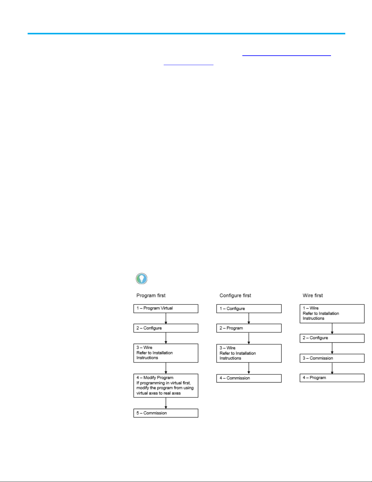
These three example scenarios describe how to get a motion solution up and
running.
Tip: Programming Virtual first is the safest method to begin with because it separates the motion
Rockwell Automation Publication MOTION-UM001I-EN-P - Septemberr 2020 11
Page 12

Preface
Motion Module
Description
filtering.
Description of the modules
This table describes the Logix 5000 motion modules.
1756-M03SE
1756-M08SE
1756-M16SE
1768-M04SE
Use a SERCOS interface module to connect the
controller to SERCOS interface drives.
• The SERCOS interface module uses high-speed, real
time, serial communication to control digital drives.
• SERCOS is the IEC 61491 Serial Real-time
Communication System protocol over a fiber optic
network.
• The module uses a fiber optic network for all the
wiring between the drives and the module.
2094-SE02F-M00-S0, 2094SE02F-M00-S1
Kinetix 6200 control modules use SERCOS interface to
communicate with the Logix controller and
EtherNet/IP to access the safety configuration tool.
1756-M02AE The 1756-M02AE module is a two-axis servo module for
drives/actuators that need a ±10V velocity or torque
reference. Use the 1756-M02AE module when the
equipment has quadrature encoder feedback.
The module also has:
• Home limit switch inputs
• Drive fault inputs
• Drive enable outputs
• 5V or 24V position registration inputs
• 250 µs position and velocity loop updates
1756-HYD02 The 1756-HYD02 module is a two-axis servo module for
hydraulic actuators that need a ±10V velocity
reference. Use the 1756-HYD02 module when the
equipment has magnostrictive linear transducer (LDT)
feedback.
The module is similar to the 1756-M02AE module with
these exceptions.
• Feed Forward adjust and single-step Auto Tune.
• Gain ratio between extend direction and retract
direction to accommodate hydraulic cylinder
dynamics.
• Intelligent transducer noise detection filtering in
hardware and firmware replaces programmable IIR
12 Rockwell Automation Publication MOTION-UM001I-EN-P - Septemberr 2020
Page 13
Motion Module
Description
Resource
Description
controllers.
Logix 5000 controller.
publication 1756-RM003.
controller.
Help for selecting
drives and motors
Additional resources
1756-M02AS The 1756-M02AS module is a two-axis servo module for
drives/actuators that need a ±10V velocity or torque
reference input. Use the 1756-M02AS module when the
equipment has Serial Synchronous Input (SSI) position
feedback.
The module is similar to the 1756-M02AE module with
these exceptions:
• Gain ratio between extend direction and retract
direction to accommodate hydraulic cylinder
dynamics.
• Intelligent transducer noise detection filtering in
hardware and firmware replaces programmable IIR
filtering.
• SSI interface consisting of Differential Clock output
and Data return signals replaces the differential
encoder interface.
Preface
Use the Motion Analyzer utility to select the Rockwell Automation drives and
motors based upon the load characteristics and typical motion application
cycles.
Access and download the program at the Motion Analyzer Software
web page.
The Motion Analyzer offers wizard-like screens to collect information about
the application. After entering the information, for example, the load inertia,
gear box ratio, feedback device, and brake requirements, the Motion Analyzer
generates an easy-to-read list of recommended motors, drives, and other
support equipment.
These documents contain additional information concerning related
Rockwell Automation products. View or download publications at the
Literature Library
. To order paper copies of technical documentation, contact
your local Rockwell Automation distributor or sales representative.
Motion Coordinate System User
Manual, publication MOTION-UM002.
Logix 5000 Controller Motion
Instructions Reference Manual,
publication MOTION-RM002.
Logix 5000 Controllers Quick Start,
publication 1756-QS001.
Provides details on how to create and
configure a coordinated motion system.
Provides a programmer with details about
motion instructions for a Logix-based
controller.
Describes how to get started
programming and maintaining Logix 5000
Rockwell Automation Publication MOTION-UM001I-EN-P - Septemberr 2020 13
Logix 5000 Controllers Common
Procedures, publication 1756-PM001.
Logix 5000 Controllers General
Instructions Reference Manual,
Provides detailed and comprehensive
information about how to program a
Provides a programmer with details about
general instructions for a Logix-based
Page 14

Preface
Resource
Description
publication 1756-RM006.
phases.
ControlLogix system.
drives.
Kinetix 7000 High Power Servo Drive
Provides details on how to plan for,
Servo drive.
combination with a Logix controller.
Kinetix 6200 and Kinetix 6500 Safe
2094-RM002.
Logix 5000 Controllers Advanced
Process Control and Drives
Instructions Reference Manual,
PhaseManager User Manual,
publication LOGIX-UM001.
ControlLogix System User Manual,
publication 1756-UM001.
CompactLogix Controllers User Manual,
publication 1768-UM001.
Analog Encoder (AE) Servo Module
Installation Instructions, publication
1756-IN047.
ControlLogix SERCOS interface Module
Installation Instructions, publication
1756-IN572.
CompactLogix SERCOS interface
Module Installation Instructions,
publication 1768-IN005.
Ultra3000 Digital Servo Drives
Installation Manual, publication 2098IN003.
Provides a programmer with details about
process and drives instructions for a
Logix-based controller.
Describes how to configure and program
a Logix 5000 controller to use equipment
Describes the necessary tasks to install,
configure, program, and operate a
Describes the necessary tasks to install,
configure, program, and operate a
CompactLogix system.
Provides installation instructions for the
Analog Encoder (AE) Servo Module, catalog
number 1756-M02AE.
Provides installation instructions for the
ControlLogix SERCOS interface modules,
catalog number 1756-M03SE, 1756-M08SE,
1756-M16SE, 1756-M08SEG.
Provides installation instructions for the
CompactLogix SERCOS interface Module,
catalog number 1768-M04SE.
Provides the mounting, wiring, and
connecting procedures for the Ultra3000
drives and standard Rockwell
Automation/Allen-Bradley motors
recommended for use with the Ultra3000
Ultra3000 Digital Servo Drives
Integration Manual, publication 2098IN005.
User Manual, publication 2099-UM001.
Kinetix 6000 Multi-axis Servo Drives
User Manual, publication 2094-UM001.
Kinteix 6200 and Kinetix 6500 Safe
Speed Monitoring Multi-axis Servo
Drives Safety Reference Manual,
publication 2094-RM001.
Torque-off Multi-axis Servo Drives
Safety Reference Manual, publication
Provides powerup procedures, system
integration, and troubleshooting tables
for the Ultra3000 digital servo drives.
mount, install, configure, and
troubleshoot the Kinetix 7000 High Power
Provides detailed installation instructions
for mounting, wiring, and troubleshooting
the Kinetix 6000 drive, and system
integration for the drive/motor
Provides information on wiring,
configuring, and troubleshooting the
safety functions of the Kinetix 6200 and
Kinetix 6500 drives.
14 Rockwell Automation Publication MOTION-UM001I-EN-P - Septemberr 2020
Page 15

Resource
Description
with the 8720MC drive.
4.1.
details.
Legal notices
Preface
8720MC High Performance Drives
Installation manual, publication
8720MC-IN001.
8720MC High Performance Drives
Integration manual, publication
8720MC-IN002.
Industrial Automation Wiring and
Grounding Guidelines, publication 1770-
Product Certifications site. Provides declarations of conformity,
Provides the mounting, wiring, and
connecting procedures for the 8720MC
and standard Rockwell Automation/AllenBradley motors recommended for use
Provides the startup, configuration, and
troubleshooting procedures for the
8720MC drive.
Provides general guidelines for installing
a Rockwell Automation industrial system.
certificates, and other certification
Rockwell Automation publishes legal notices, such as privacy policies, license
agreements, trademark disclosures, and other terms and conditions on the
Legal Notices
page of the Rockwell Automation website.
End User License Agreement (EULA)
You can view the Rockwell Automation End User License Agreement (EULA)
by opening the license.rtf file located in your product's install folder on your
hard drive.
The default location of this file is:
C:\Program Files (x86)\Common Files\Rockwell\license.rtf.
Open Source Software Licenses
The software included in this product contains copyrighted software that is
licensed under one or more open source licenses.
You can view a full list of all open source software used in this product and
their corresponding licenses by opening the oss_license.txt file located your
product's OPENSOURCE folder on your hard drive. This file is divided into
these sections:
• Components
Includes the name of the open source component, its version number,
and the type of license.
• Copyright Text
Includes the name of the open source component, its version number,
and the copyright declaration.
Rockwell Automation Publication MOTION-UM001I-EN-P - Septemberr 2020 15
Page 16

Preface
• Licenses
Includes the name of the license, the list of open source components
citing the license, and the terms of the license.
The default location of this file is:
C:\Program Files (x86)\Common Files\Rockwell\Help\<product
name>\Release Notes\OPENSOURCE\oss_licenses.txt.
You may obtain Corresponding Source code for open source packages
included in this product from their respective project web site(s).
Alternatively, you may obtain complete Corresponding Source code by
contacting Rockwell Automation via the Contact form on the Rockwell
Automation website:
http://www.rockwellautomation.com/global/aboutus/contact/contact.page. Please include "Open Source" as part of the request
text.
16 Rockwell Automation Publication MOTION-UM001I-EN-P - Septemberr 2020
Page 17
Introduction for Configure
Analog Motion
Create a controller project
for Configure Analog Motion
Chapter 1
Configure analog motion
Use this chapter for step-by-step procedures on how to configure analog
motion control.
Use these instructions to create a controller project.
To create a controller project for Configure SERCOS Motion:
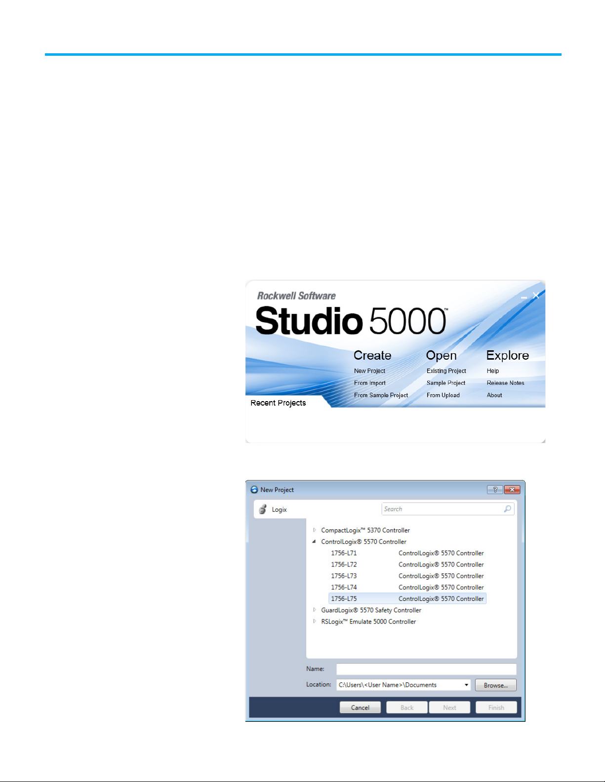
1. Open the Studio 5000 software.
2. In the Studio 5000 launcher, under Create, select New Project.
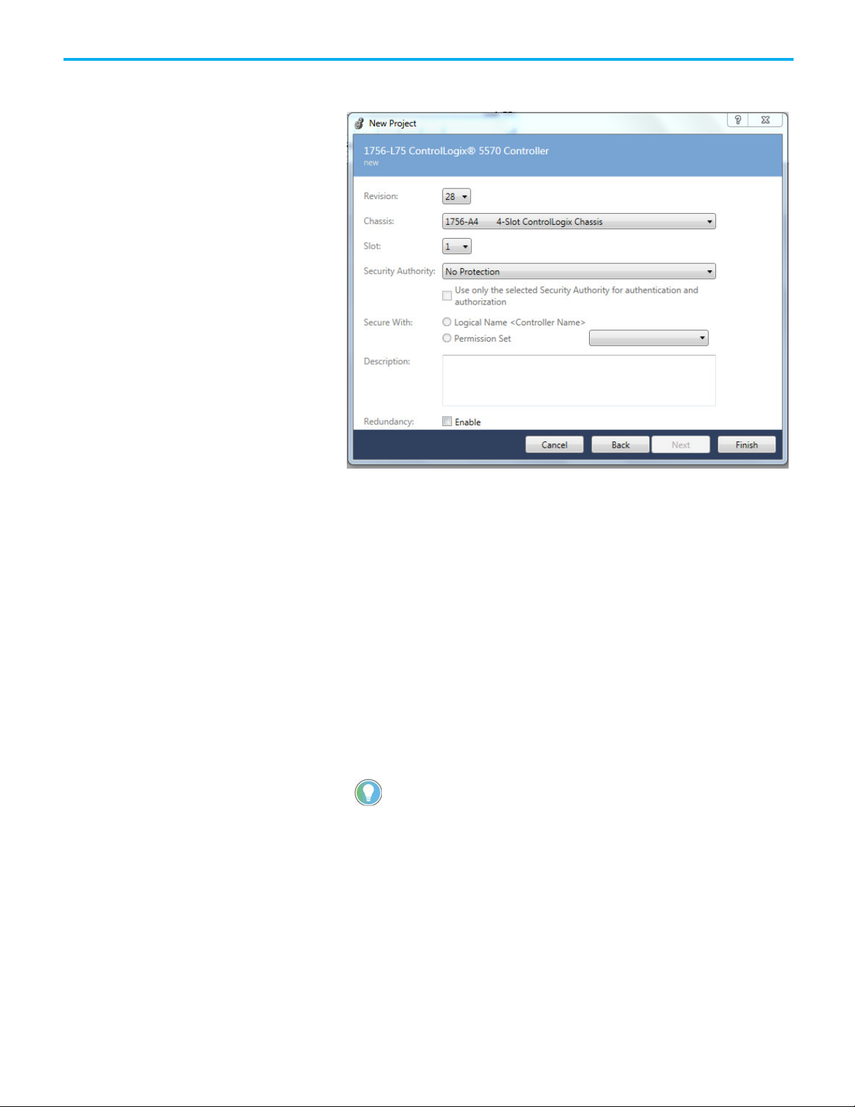
3. On the New Project dialog box, choose a controller.
Rockwell Automation Publication MOTION-UM001I-EN-P - Septemberr 2020 17
Page 18
Chapter 1 Configure analog motion
Tip: Guest User permissions are cached within the project. The Logix Designer application
Administration Console.
4. In the Name box, type a name for the controller project, and select
Next.
5. In the Revision list, select the revision number for the controller.
6. In the Chassis list, select the type of chassis that holds the controller.
7. In the Slot list, select the physical slot where the controller is located.
8. In the Security Authority list, select a security option:
• No Protection - All users can view and edit the project.
• FactoryTalk Security - Only users authenticated through
FactoryTalk Security can view and edit the project
9. (optional) Select Use only the selected Security Authority for
authentication and authorization to associate this project with a
specific Security Authority. When this check box is selected, users
interacting with this project must be authenticated and authorized by
the same Security Authority that was used to secure the project.
Otherwise, unauthenticated users must rely on Guest User
permissions.
uses Guest User permissions when the project is opened but not connected to the
FactoryTalk Security Authority that secures the project. By default, all Guest User
permissions are denied. Guest User permissions are configured in the FactoryTalk
10. Select Logical Name <Controller Name> or Permission Set to apply
specific permissions to the controller.
Select Logical Name <Controller Name> to apply a Logical Name in
FactoryTalk Services Platform that has the same name as the
controller. If there is no existing Logical Name that matches the
controller name, a new Logical Name is created with the controller's
name. The new Logical Name inherits permissions from its parent
18 Rockwell Automation Publication MOTION-UM001I-EN-P - Septemberr 2020
Page 19

bytes per character, resulting in less than 128 characters.
Set time synchronization
Chapter 1 Configure analog motion
resource. See FactoryTalk Help for more information on how networks
and devices inherit security permissions.
Select Permission Set to apply a specific set of permissions to the
controller. The permission sets in the list are maintained in
FactoryTalk Services Platform and identify a set of actions that are
allowed or denied for a particular user and computer combination.
11. (optional) In the Description box, type a description for the controller.
Tip: The description is limited to 128 bytes. Standard ASCII characters consume 1 byte per
character, allowing for 128 characters. Characters in some languages require up to three
12. (optional) Select Enable redundancy if this project supports an
automatic transfer of project control to a redundant controller in case
of primary controller failure.
13. Select Finish.
See also
Add a SERCOS motion module
for Configure Analog Motion
Add a SERCOS interface drive module
Add a motion group for Configure SERCOS motion
1. Add an axis
Time Synchronization in ControlLogix is called CIP Sync. CIP Sync is a layer
of functionality that Rockwell Automation has developed on top of the IEEE
1588 PTP protocol. CIP Sync maintains accurate time synchronization of
automation solutions.
This setting establishes the module to participate in time synchronization. In
systems with multiple processors, all controllers must have time
synchronization enabled if they use CSmainT/PTP time. The 1756-ENxT
communication modules win the arbitration over any processor.
To set time synchronization for Configure SERCOS Motion:
1. In the Controller Organizer, double-click the controller.
Rockwell Automation Publication MOTION-UM001I-EN-P - Septemberr 2020 19
Page 20
Chapter 1 Configure analog motion
IMPORTANT
Add an analog module
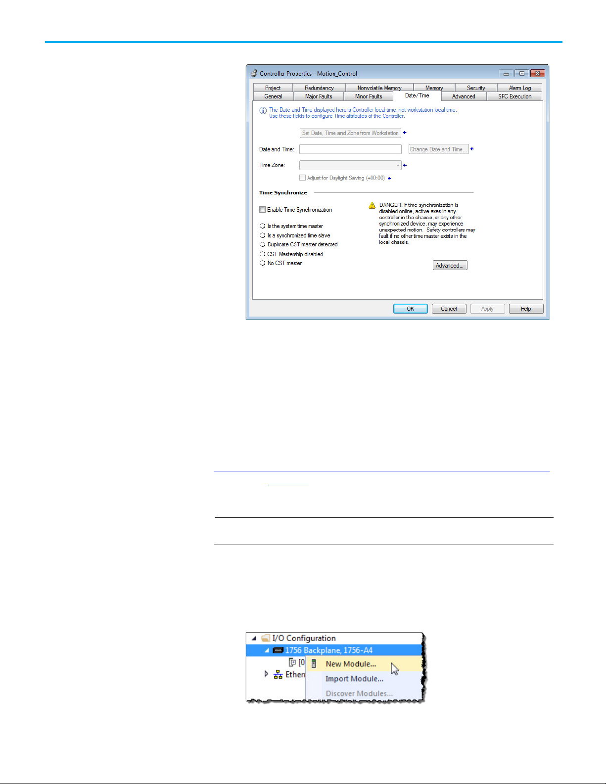
2. On the Controller Properties dialog box, select the Date/Time tab.
3. Select Enable Time Synchronization.
4. Select OK.
Without intervention, the Grandmaster is PTP and CST master. Use the
settings on the Advanced dialog box to let this module win the arbitration
over other processors and communication modules in the chassis.
See also
Integrated Architecture and CIP Sync Configuration Application Technique,
publication IA-AT003
Use these instructions to add an analog module to the system.
For all modules, use the firmware revision that goes with the firmware revision of the
controller. See the release notes for the controller’s firmware.
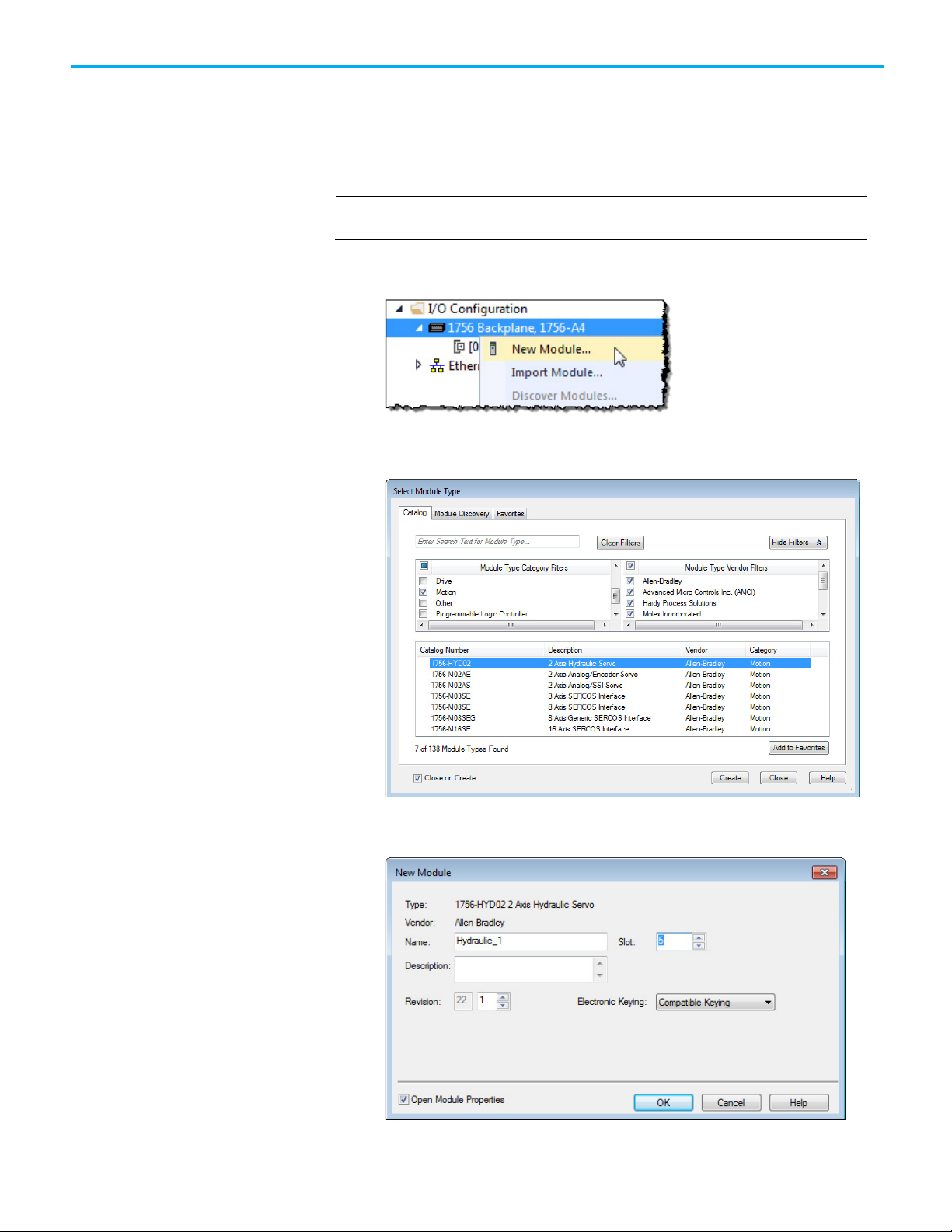
To add an analog module:
1. In the Controller Organizer, right-click the backplane and select New
Module.
20 Rockwell Automation Publication MOTION-UM001I-EN-P - Septemberr 2020
Page 21
WARNING: Disable Keying should never be used with motion modules.
Chapter 1 Configure analog motion
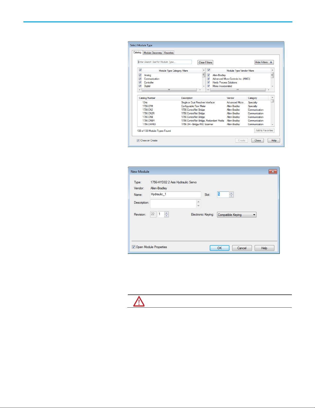
2. On the Select Module Type dialog box, choose the module to add to the
project.
3. Select Close on Create, and select Create.
4. On the New Module dialog box, in Name, type a name for the module.
Rockwell Automation Publication MOTION-UM001I-EN-P - Septemberr 2020 21
5. In Slot, choose the number that corresponds to the physical slot that
contains the module.
6. (optional) In Description, type a description.
7. In Electronic Keying, choose a keying option of either Compatible
Keying or Exact Match.
8. Select Open Module Properties, and select OK. Continue with the
procedure to modify the properties for the module.
See also
Electronic Keying
Page 22
Chapter 1 Configure analog motion
Modify properties for
an analog module
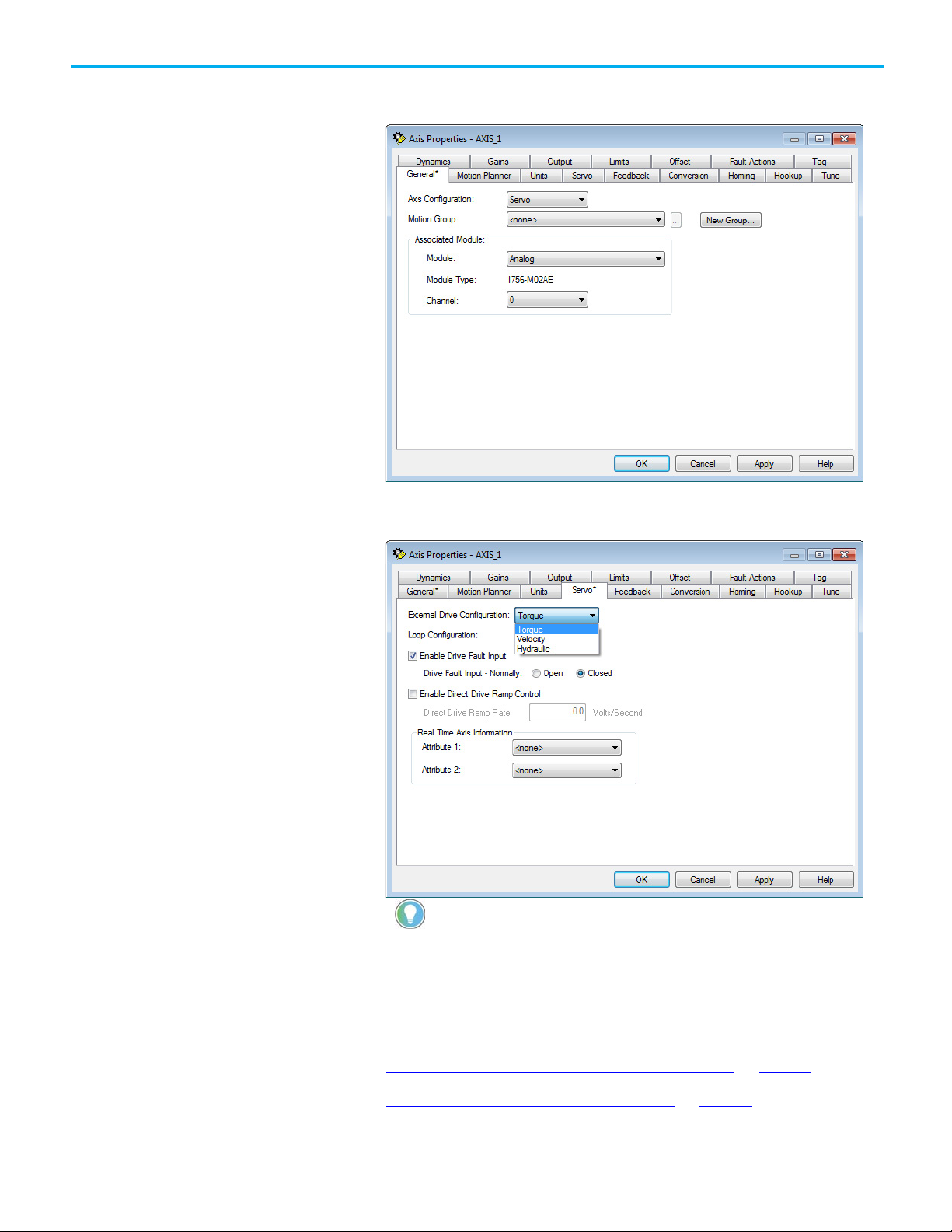
Use the Module Properties dialog box to modify properties and associate axes
with the module.
To modify the properties for an analog module:
1. In the Controller Organizer, double-click the module.
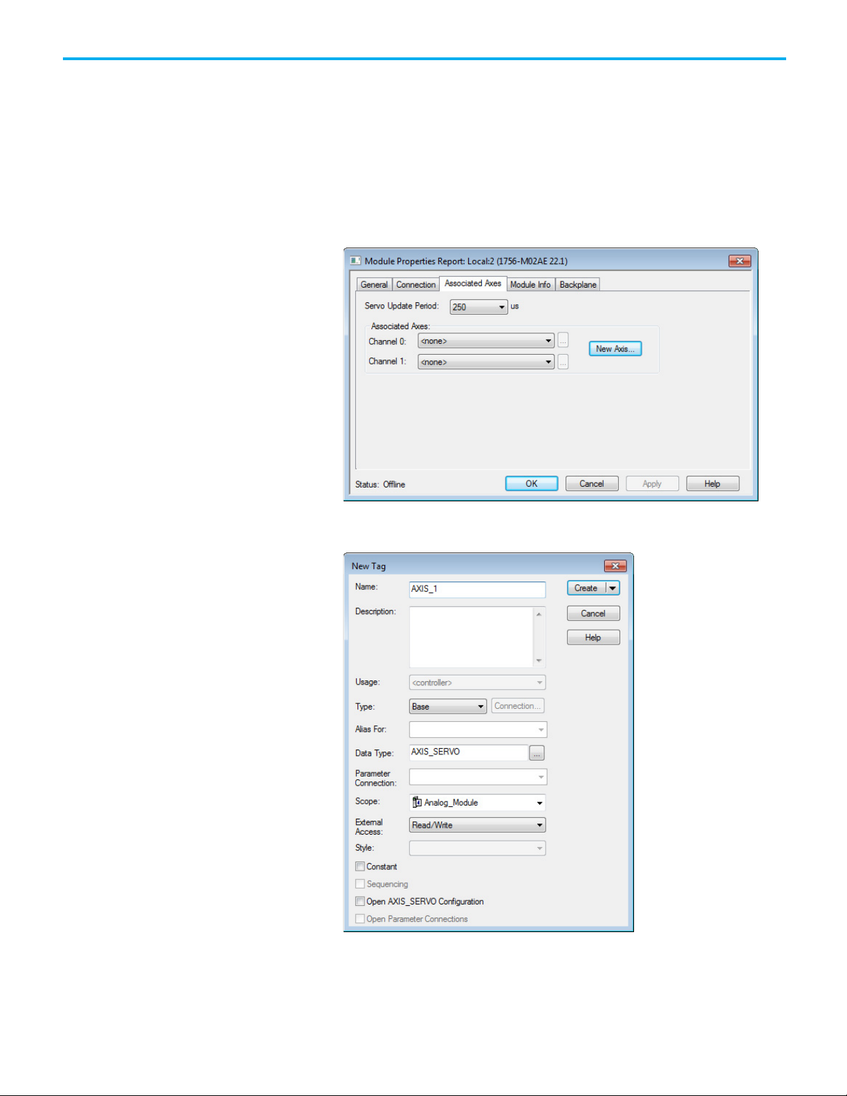
2. On the Module Properties Report dialog box, select the Associated
Axes tab.
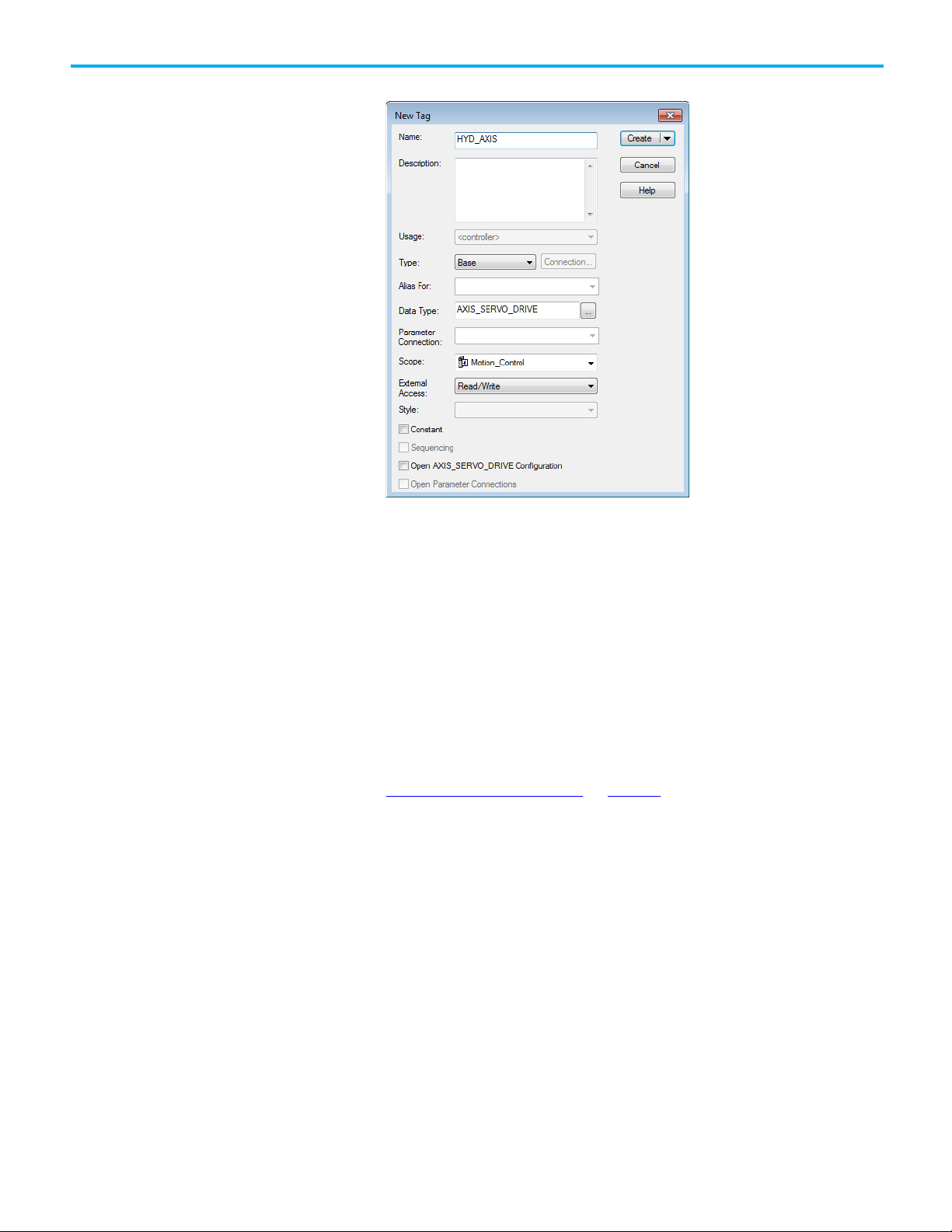
3. Select New Axis to create an axis to associate with this module.
4. On the New Tag dialog box, type a name for the Axis and select Create.
22 Rockwell Automation Publication MOTION-UM001I-EN-P - Septemberr 2020
5. On the Module Properties Report dialog box, in Channel 0, choose the
new axis to assign it to the module.
6. Select Browse to open the Axis Properties dialog box for the
associated axis.
Page 23
Hydraulic can only be selected for a hydraulic module.
Chapter 1 Configure analog motion
7. On the Axis Properties dialog box, in Module on the General tab,
choose the module to associate with the axis.
8. Select the Servo tab.
9. In External Drive Configuration, choose the drive configuration.
Rockwell Automation Publication MOTION-UM001I-EN-P - Septemberr 2020 23
Tip: If configuring a torque drive, the drive must be able to be configured for torque.
10. Select OK.
See also
Add a motion group for Configure Analog Module on page 27
Add an axis for Configure Analog Module on page 30
Page 24
Chapter 1 Configure analog motion
IMPORTANT
Add a hydraulic
drive module
Use these instructions to add a hydraulic drive module if included in the
configuration.
To add a hydraulic drive module:
For all modules, use the firmware revision that goes with the firmware revision of the
controller. See the release notes for the controller’s firmware.
1. In the Controller Organizer, right-click the backplane and select New
Module.
2. On the Select Module Type dialog box, choose the hydraulic drive
module to add to the project.
24 Rockwell Automation Publication MOTION-UM001I-EN-P - Septemberr 2020
3. Select Close on Create, and select Create.
4. On the New Module dialog box, in Name, type a name for the module.
Page 25
WARNING: WARNING: Never select Disable Keying with motion modules
Modify properties for a
hydraulic drive module
Chapter 1 Configure analog motion
5. In Slot, choose the number that corresponds to the physical slot that
contains the module.
6. (optional) In Description, type a description.
7. In Electronic Keying, choose either Compatible Keying or Exact
Match.
8. Select Open Module Properties.
9. Select OK. Continue with the instructions to modify the properties for
the hydraulic drive module.
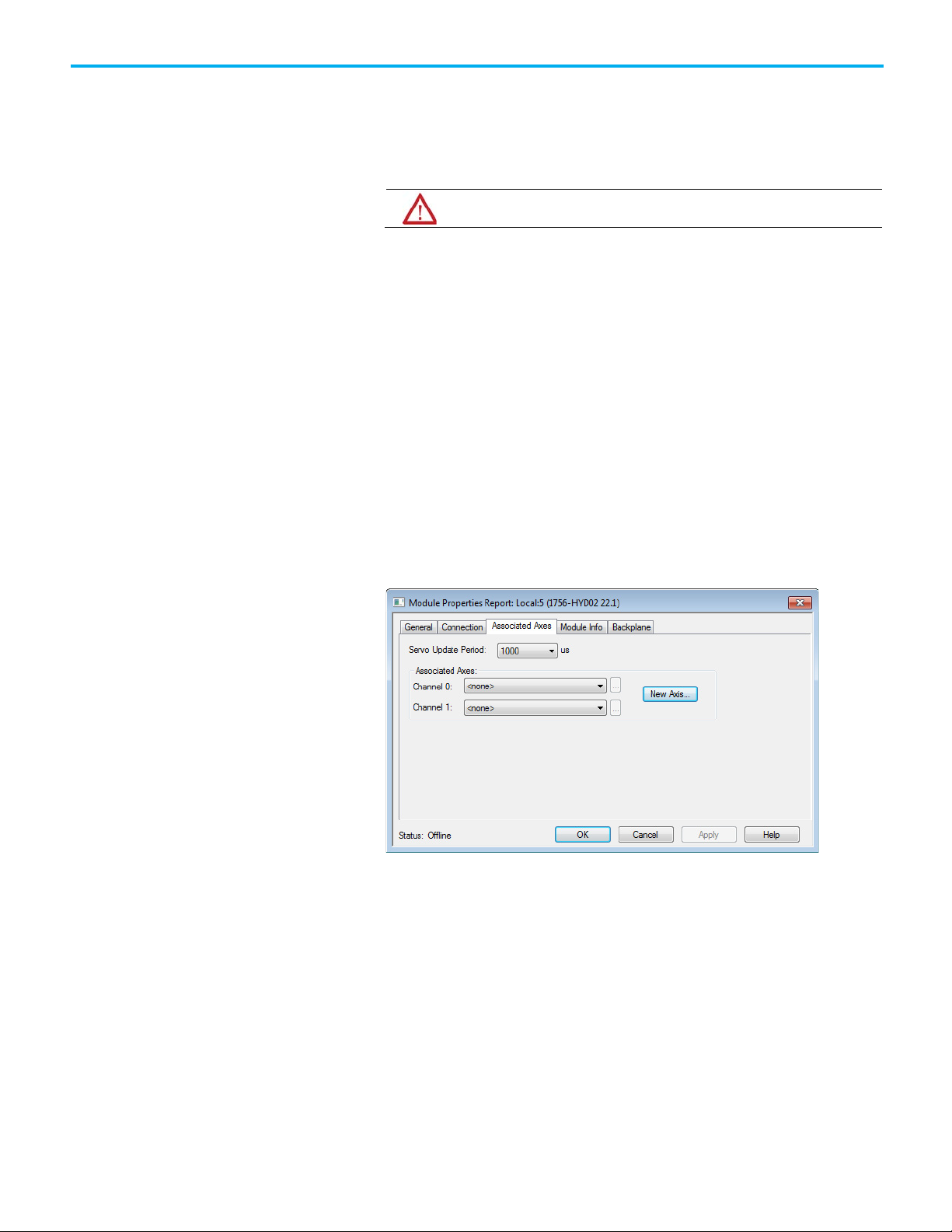
Configure the feedback type for a hydraulic drive. Based on the length of the
feedback, the Servo Update Period must be configured. This setting is unique
for the 1756-HYD02 module. If the Servo Update Period is not configured
correctly, the axis does not work.
To modify the properties for a hydraulic drive module:
1. If the Module Properties Report dialog box is not already open, in the
Controller Organizer, double-click the hydraulic drive module.
2. On the Module Properties Report dialog box, select the Associated
Axes tab.
Rockwell Automation Publication MOTION-UM001I-EN-P - Septemberr 2020 25
3. Select New Axis to create an AXIS_SERVO tag to associate to one of
the channels.
Page 26
Chapter 1 Configure analog motion
Configure the
4. On the New Tag dialog box, in Name, type a name for the axis tag.
5. Select Create.
6. (optional) Repeat steps 3 through 5 if an additional axis is required.
7. On the Module Properties Report dialog box, in Channel 0, choose an
axis.
8. (optional) In Channel 1, choose an axis.
9. In Servo Update Period, choose the periodic rate at which the module
closes the servo loop for an axis.
10. Select OK.
feedback type
26 Rockwell Automation Publication MOTION-UM001I-EN-P - Septemberr 2020
See also
Configure the feedback type on page 26
Use these instructions to configure the feedback type for the axis.
1. In the Controller Organizer, double-click the axis.
Page 27
IMPORTANT
Add a motion group for
Chapter 1 Configure analog motion
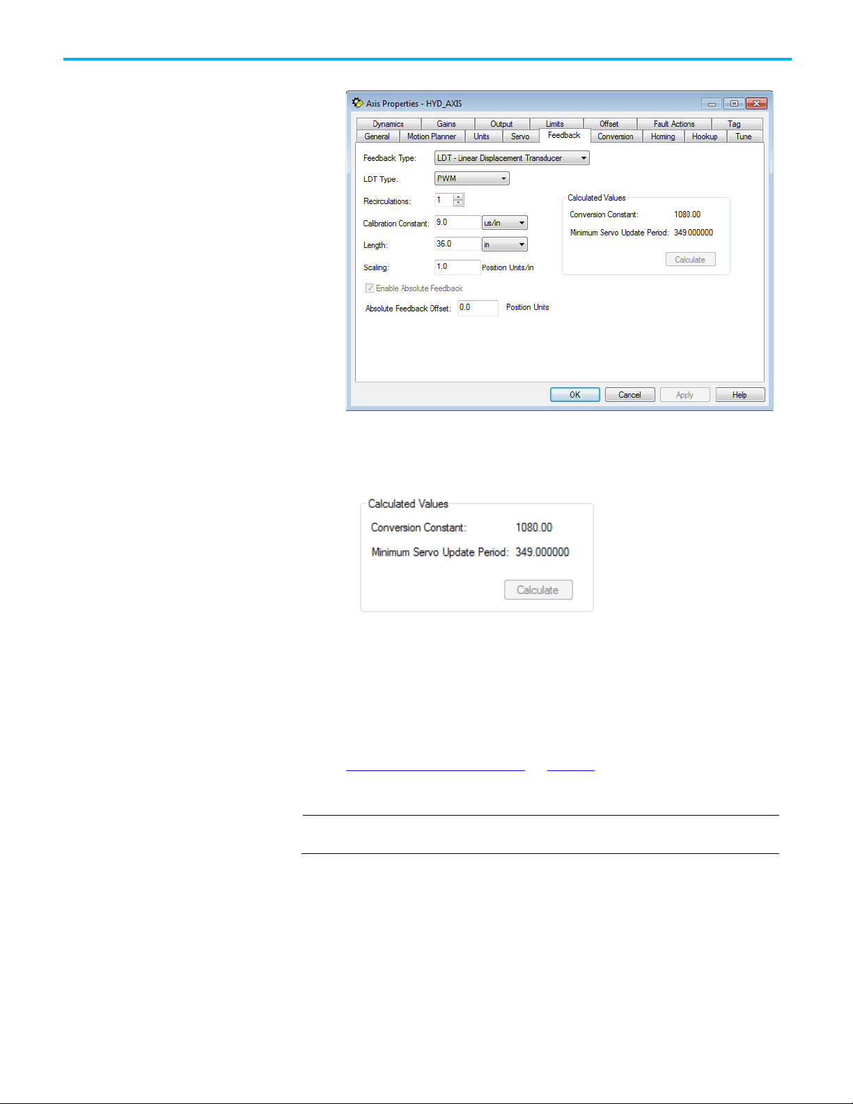
2. On the Axis Properties dialog box, select the Feedback tab.
3. In Feedback Type, choose the feedback type.
4. In Calibration Constant, choose the value and select Calculate. The
minimum servo update period for the configured feedback appears.
Configure Analog Motion
5. If necessary, return to the Module Properties dialog box, and modify
the settings on the Associated Axis tab.
See also
Feedback tab - AXIS_SERVO on page 92
Use these instructions to add a motion group.
Only one motion group can be created for each project.
Rockwell Automation Publication MOTION-UM001I-EN-P - Septemberr 2020 27
Page 28
Chapter 1 Configure analog motion
Set the Base Update Period
To add a motion group for Configure Analog Motion:
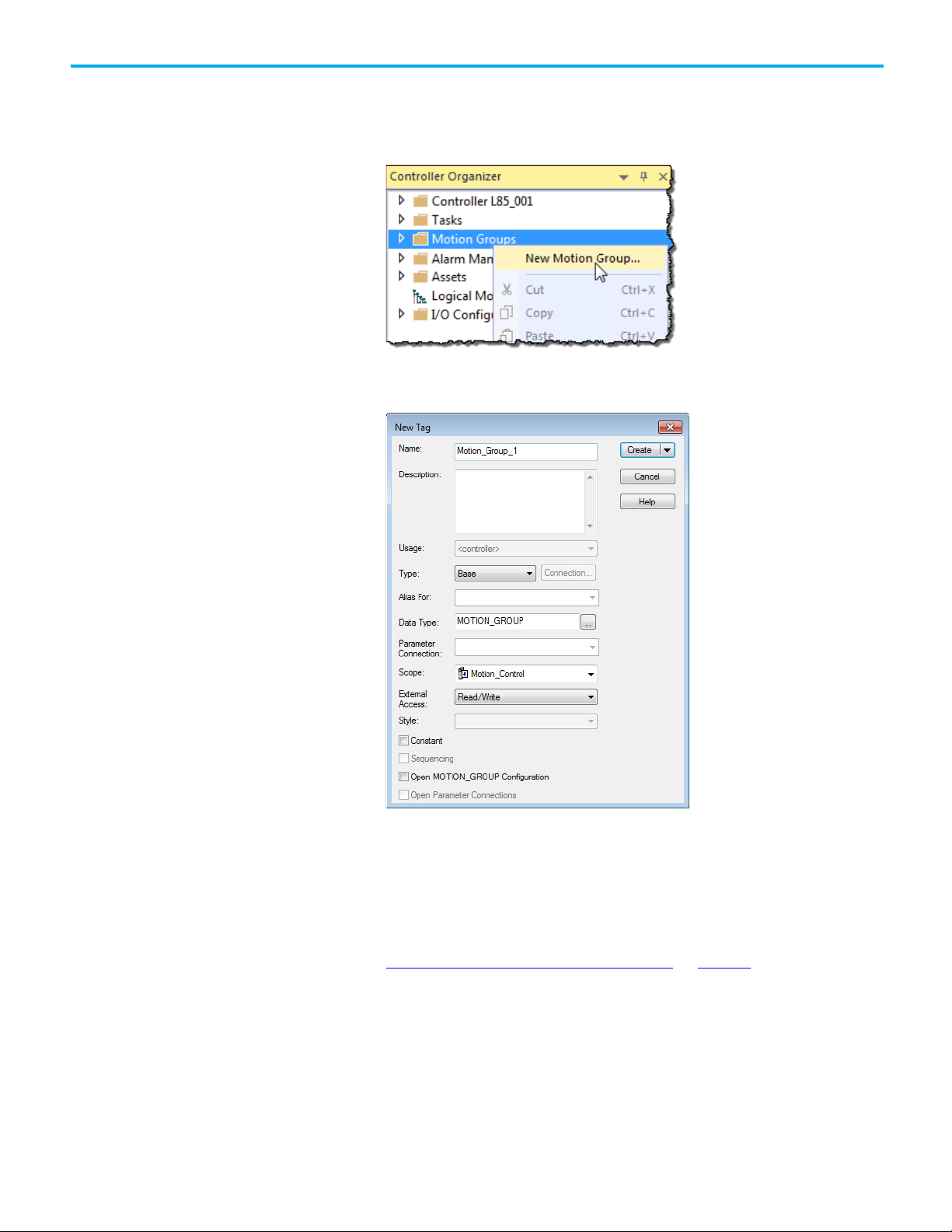
1. In the Controller Organizer, right-click Motion Groups and select New
Motion Group.
2. On the New Tag dialog box, in Name, type a name for the motion
group.
28 Rockwell Automation Publication MOTION-UM001I-EN-P - Septemberr 2020
3. (optional) In Description, type a description.
4. Select Create.
See also
Add an axis for Configure Analog Motion on page 30
The Base Update Period (also known as the Coarse Update Period) is how
often the motion planner runs. The motion planner is the part of the
controller that handles position and velocity information for the axes. When
the motion planner runs, it interrupts most other tasks regardless of their
priority.
Page 29
Guideline
Description
Save Controller’s Time
Leave at least half the controller’s time for the scan
Base Update Period and
For analog motion modules, set the Base Update
motion module.
Chapter 1 Configure analog motion
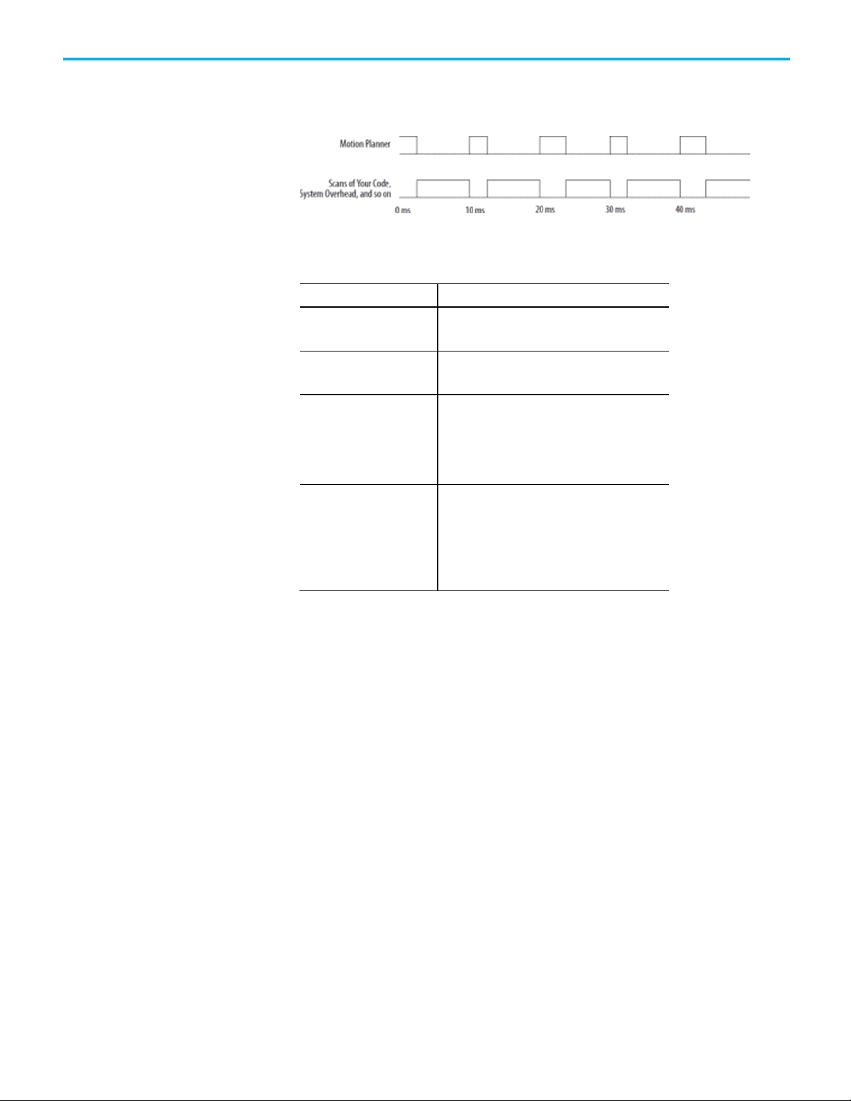
Example: If the Base Update Period is set to 10 ms, then every 10 ms the
controller stops scanning the code and performing other system overhead
tasks, and runs the motion planner.
Use these guidelines to set the Base Update Period.
Number of Axes 1756-L6x controller 4 axes/ms
x
controller8 axes/ms
1756-L7
of all the code.
Base Update Period and
SERCOS modules
Analog modules
For SERCOS interface motion modules, set the Base
Update Period to a multiple of the cycle time of the
motion module.
Example: If the cycle time is 2 ms, set the Base
Update Period to 8 ms, 10 ms, 12ms, and so on.
Period to:
• At least 3 times the servo update period of the
motion module.
• A multiple of the servo update period of the
To set the Base Update Period:
1. In the Controller Organizer, double-click the motion group.
Rockwell Automation Publication MOTION-UM001I-EN-P - Septemberr 2020 29
Page 30
Chapter 1 Configure analog motion
there is no need to open the Axis Schedule dialog box.
Add an axis for Configure
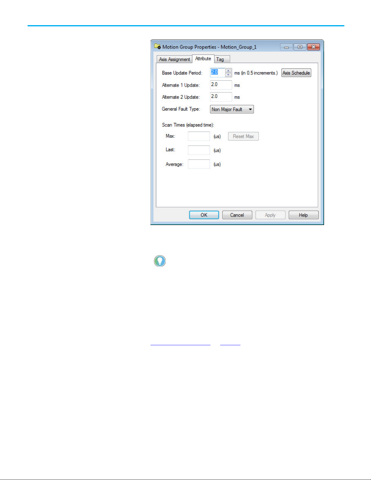
2. Select the Attribute tab.
Analog Motion
3. In Base Update Period, choose the update period using the guidelines
mentioned earlier. The valid values range from 0.5 to 32, in 0.5
increments.
Tip: The Axis Schedule button opens the Axis Schedule dialog box to schedule the base
and alternate update periods and assign axes to them. Since axes used in coordinate
system objects cannot be multiplexed, only the Base Update Period is used. Therefore,
4. In General Fault Type, choose Non Major Fault.
5. Select OK.
See also
1. Manage motion faults on page 38
Use these instructions to add an axis for each of the drives.
30 Rockwell Automation Publication MOTION-UM001I-EN-P - Septemberr 2020
Page 31

Configure an axis for
Chapter 1 Configure analog motion
To add an axis for Configure Analog Motion:
1. In the Controller Organizer, right-click the motion group and select
New Axis.
2. Choose the data type based on these guidelines.
• If using one of these motion modules, select AXIS_SERVO.
• 1756-M02AE
• 1756-HYD02
• 1756-M02AS
Configure Analog Motion
• To use a virtual configuration (no hardware), select
AXIS_VIRTUAL.
3. On the New Tag dialog box, in Name, type a name for the axis.
4. (optional) In Description, type a description for the axis.
5. Select Create.
See also
Configure an axis for Configure Analog Motion on page 31
Use these steps to configure the axis of an analog module.
To configure an axis for Configure Analog Motion:
1. In the Controller Organizer, double-click the axis.
2. On the General tab, in Module, select the name of the drive for this
axis.
Rockwell Automation Publication MOTION-UM001I-EN-P - Septemberr 2020 31
Page 32

Chapter 1 Configure analog motion
Set the homing sequence
3. Select the Units tab, and in Position Units, enter the units in which to
program.
4. Select the Conversion tab, and in Positioning Mode and Conversion
Constant, enter the conversion details.
for Configure Analog Motion
See also
Axis properties on page 85
Use the Homing tab in the Axis Properties dialog box to set up the homing
mode and sequence for the module.
To set the homing sequence:
1. Select the Homing tab, and in Mode, choose the homing mode.
32 Rockwell Automation Publication MOTION-UM001I-EN-P - Septemberr 2020
2. In Position, type the position units.
3. In Sequence, choose the sequence type.
Page 33

Chapter 1 Configure analog motion
4. For all sequence types except Intermediate, in Description, choose the
active home sequence direction, and then in Speed and Return Speed,
set the homing speeds.
5. Select OK to apply the changes.
See also
1. Home an axis on page 77
Rockwell Automation Publication MOTION-UM001I-EN-P - Septemberr 2020 33
Page 34

Page 35

modifying.
Test
Description
feedback
Introduction for
Test axis wiring
Chapter 2
Commission and tune
This chapter discusses how to commission an axis for a motion application.
Commission and Tune
Download a program to the controller
Before commissioning and tuning an axis, download the program to the
controller.
To download a program to the controller:
1. With the keyswitch, place the controller in Program or Remote
Program mode.
2. From the Communications menu, select Download.
3. Confirm to complete the download procedure.
4. Select Download.
5. When the download is complete, place the controller in Run/Test
mode.
The status and compiler messages appear in the status bar.
Tip: When multiple workstations connect to the same controller using Logix Designer
application and invoke the Axis Wizard or Axis Properties dialog box, the firmware only
lets the first workstation make changes to axis attributes. The second workstation can
view the changes, but not edit them.
If an axis in a motion group is open for edit, then any other workstation only gets read-only
for any axis in that workstation, even if it is not the axis that the first workstation is
and direction
Rockwell Automation Publication MOTION-UM001I-EN-P - Septemberr 2020 35
See also
Tune a SERCOS axis on page 36
Tune an analog axis on page 37
Use these tests on the Hookup tab in the Axis Properties dialog box to test the
axis wiring and direction.
Test marker Checks that the drive gets the marker pulse.
Manually move the axis for this test.
Test feedback Checks the polarity of the feedback. Manually
move the axis for this test.
Test command and
Checks the polarity of the drive.
Page 36

Chapter 2 Commission and tune
Do not change the polarity after performing the tests. Unexpected motion may occur.
IMPORTANT
• Before tuning an axis, make sure no one is in the way of the axis.
However, when used incorrectly, these settings can cause axis instability. See Tune.
Tune a SERCOS axis
ATTENTION: These tests make the axis move even with the controller in remote program
mode.
• Before performing the tests, make sure no one is in the way of the axis.
To test the axis wiring and direction:
1. Download a program to the controller.
2. Place the controller in REM.
3. In the Controller Organizer, double-click the axis.
4. On the Axis Properties dialog box, select the Hookup tab.
Follow all the dialogs or the information derived from the test is not saved to
the axis configuration.
5. Select Test Marker and follow the additional dialog box instructions.
6. Select Test Feedback and follow the additional dialog box instructions.
7. Select Test Command & Feedback and follow the additional dialog box
instructions.
See also
Hookup tab - AXIS_SERVO on page 106
Hookup tab - AXIS_SERVO_DRIVE on page 107
Use the settings on the Tune tab in the Axis Properties dialog box to
configure and initiate the axis tuning sequence for a SERCOS axis.
• ATTENTION: When tuning an axis, it moves even with the controller in remote program
mode. In that mode, the code is not in control of the axis.
The default tuning procedure tunes the proportional gains. Typically, tune the
proportional gains first and see how the equipment runs.
Tip: Where tighter positioning is required, Integral gain and feedforward constants can be selected.
To tune an SERCOS axis:
1. Download a program to the controller.
2. Place the controller in REM.
3. In the Controller Organizer, double-click the axis.
36 Rockwell Automation Publication MOTION-UM001I-EN-P - Septemberr 2020
Page 37

Tune an analog axis
Chapter 2 Commission and tune
4. Select the Tune tab.
5. In Travel Limit, type the limit of movement for the axis during the
tuning procedure.
6. In Speed, type the maximum speed for the equipment.
7. Select Start Tuning.
8. Accept the changes to save the data derived from the tune as part of the
axis configuration.
See also
Tune tab - AXIS_SERVO, AXIS_SERVO_DRIVE on page 108
Use the settings on the Tune tab in the Axis Properties dialog box to
configure and initiate the axis tuning sequence for an analog axis.
• ATTENTION: When tuning an axis, it moves even with the controller in remote program
mode. In that mode, the code is not in control of the axis.
• Before tuning an axis, make sure no one is in the way of the axis.
The default tuning procedure tunes the proportional gains. Typically, tune the
proportional gains first and see how the equipment runs.
To tune an analog axis:
1. Download a program to the controller.
2. Place the controller in REM.
3. In the Controller Organizer, double-click the axis.
Rockwell Automation Publication MOTION-UM001I-EN-P - Septemberr 2020 37
Page 38

Chapter 2 Commission and tune
Type
Description
Example
Troubleshoot faults
Manage motion faults
4. Select the Tune tab.
5. In Travel Limit, type the limit of movement for the axis during the
tuning procedure.
6. In Speed, type the maximum speed for the equipment.
7. Select Start Tuning.
See also
Tune tab - AXIS_SERVO, AXIS_SERVO_DRIVE on page 108
This table explains the types of motion faults.
Instruction error Caused by a motion instruction:
• Instruction errors do not impact controller operation.
• Examine the error code in the motion control tag to see why an instruction has
an error.
• Fix instruction errors to optimize execution time and make sure that the code
is accurate.
Fault Caused by a problem with the servo loop:
• Choose whether motion faults give the controller major faults.
• Can shut down the controller if the fault condition is not corrected.
By default, the controller keeps running when there is a motion fault. As an
option, configure motion faults to cause a major fault and shut down the
controller.
A Motion Axis Move (MAM) instruction with a
parameter out of range
• Loss of feedback
• Actual position exceeding an overtravel limit
38 Rockwell Automation Publication MOTION-UM001I-EN-P - Septemberr 2020
Use these instructions to select a non-major fault as the fault mechanism for
the motion group.
Page 39

Minor, and I/O Faults Programming Manual, publication 1756-PM014.
Configure the fault actions
Chapter 2 Commission and tune
To manage motion faults:
1. Choose a Non-Major Fault.
Tip: If selecting a Major Fault, develop a Fault handler. See
2. In the Controller Organizer, double-click the motion group.
3. Select the Attribute tab.
4. In General Fault Type, choose Non Major Fault.
Logix 5000 Controllers Major,
for an axis
5. Select OK.
6. In the Controller Organizer, drag the programs into the Controller
Fault Handler folder so the program runs when a fault occurs.
See also
Set the fault action for an axis on page 40
Use the fault actions to set how an axis responds to faults. The type of faults
depends on the type of axis its configuration.
Rockwell Automation Publication MOTION-UM001I-EN-P - Septemberr 2020 39
Page 40

Chapter 2 Commission and tune
To
Then choose
Description
For this axis type
When the fault happens
the axis with the fault.
For this axis type
When the fault happens
AXIS_SERVO
Planner decelerates axis motion to zero speed based on Maximum
• The drive enable output is deactivated.
fault before moving the axis.
For this axis type
When the fault happens
AXIS_SERVO_DRIVE
Control of the drive’s servo loop is maintained.
Set the fault action
Shut down the axis and let it coast
to a stop
Disable the axis and let the drive
stop the axis using the best
available stopping method
Leave the servo loop on and stop
the axis at its Maximum
Deceleration rate
Shutdown Shutdown is the most severe action. Use it for faults that could endanger the machine or the operator
power is not removed quickly and completely.
AXIS_SERVO • Axis servo action is disabled.
• The servo amplifier output is zeroed.
• The drive enable output is deactivated.
• The OK contact of the servo module opens. Use this to open the E-
Stop string to the drive power supply.
•
This impacts both axes associated with the analog motion, not just
AXIS_SERVO_DRIVE • Axis servo action and drive power structure are immediately
disabled.
• The axis coasts to a stop unless there is some form of external
braking.
Disable Drive
•
configured declaration using Trap Acc/Dec.
• Axis servo action is off.
• The servo amplifier output is zeroed.
AXIS_SERVO_DRIVE • Planner decelerates axis motion to zero speed based on Maximum
configured declaration using Trap Acc/Dec.
• If the axis does not stop in the Stopping Time, the servo action and
the power structure are disabled.
Stop Motion Use this fault action for less severe faults. It is the gentlest way to stop. Once the axis stops, clear the
Write application code to handle
the fault
for an axis
AXIS_SERVO The axis slows to a stop at the Maximum Deceleration Rate without
disabling servo action or the servo module’s Drive Enable output.
•
• The axis slows to a stop at the Maximum Deceleration rate without
disabling the drive.
Status Only Use this fault action only when the standard fault actions are not appropriate. With this fault action,
write code to handle the motion faults. For Stop Motion or Status Only, the drive must stay enabled for
the controller to continue to control the axis. Selecting Status Only only lets motion continue if the
drive itself is still enabled and tracking the command reference.
Use settings on the Fault Actions tab in the Axis Properties dialog box to
configure the fault actions for the axis.
To set the fault actions for an axis:
1. In the Controller Organizer, double-click an axis.
40 Rockwell Automation Publication MOTION-UM001I-EN-P - Septemberr 2020
Page 41

IMPORTANT
Blocks the controller from using an axis because the axis is faulted
or not installed.
Inhibit an axis
Chapter 2 Commission and tune
2. Select the Fault Actions tab.
3. Set the desired attributes and select OK. (An analog axis has fewer
fault action selections than a SERCOS axis.)
See also
Fault Actions tab - AXIS_SERVO on page 136
Fault Actions tab - AXIS_SERVO_DRIVE on page 138
Inhibit an axis to block the controller from using an axis because the axis has
faulted or is not installed. Also inhibit an axis to let the controller use other
axes. Use this information to determine when to inhibit an axis.
Inhibiting an axis takes down ALL axes on the motion module or ring. The noninhibited axes then phase back up. Un-inhibiting an axis causes the same behavior.
Rockwell Automation Publication MOTION-UM001I-EN-P - Septemberr 2020 41
Lets the controller use the other axes.
Page 42

Chapter 2 Commission and tune
Before inhibiting or uninhibiting an axis, turn off
The controller automatically restarts the connections. The SERCOS ring also phases back up.
Inhibit only certain types of axes.
Before you begin
Example 1
If the equipment needs between 8 and 12 axes, depending on the application,
create one project for all 12 axes. When determining how many axes are
needed, inhibit the axes that are not needed.
Example 2
If two production lines use the same SERCOS ring and one of the lines gets a
fault, inhibit the axes on that line. This allows the other line to run while the
fault is addressed.
Tip: If an axis is faulted, all axes are still available. If there is a hardware issue with one of the
"drives," inhibit the axis and remove the faulty hardware. When the ring phases back up, the
inhibited axis (with its missing hardware) does prevent the rest of the axes from operating.
See also
all axes.
Example: Inhibit an axis on page 43
Example: Uninhibit an axis on page 44
This table explains what to do before beginning.
Before beginning:
1. Stop all motion.
2. Open the servo loops of all axes. Use an instruction such as the Motion Servo Off (MSF) instruction.
This allows motion to stop under control. Otherwise the axes turn off on their own when inhibiting or
uninhibiting one of them.
Inhibit only these types of axes.
• AXIS_SERVO
• AXIS_SERVO_DRIVE
42 Rockwell Automation Publication MOTION-UM001I-EN-P - Septemberr 2020
Page 43

To inhibit all axes of a motion module, inhibit
the module.
1.
Example: Inhibit an axis
Chapter 2 Commission and tune
Inhibit all axes of a motion module?
• YES — Inhibit the motion module.
• NO — Inhibit the individual axes.
Inhibit all axes of a module on an individual basis. However, inhibiting the module is more efficient than
inhibiting each axis.
Important: If inhibiting an axis on a drive, inhibit all action on the drive, including any half axes. Be aware
of all action on a drive before inhibiting the axis.
Example: If the motion module has two axes to inhibit, just inhibit the module.
If inhibiting all axes on a SERCOS ring, the drives phase up to phase 2. This happens whether inhibiting each
axis individually or inhibiting the motion module.
Make sure all axes are off.
Rockwell Automation Publication MOTION-UM001I-EN-P - Septemberr 2020 43
Page 44

Chapter 2 Commission and tune
1. Wait for the inhibit process to finish.
Example: Uninhibit an axis
1. Use a one-shot instruction to trigger the inhibit.
1. Inhibit the axis.
1. Make sure all axes are off.
44 Rockwell Automation Publication MOTION-UM001I-EN-P - Septemberr 2020
Page 45

Test an axis with Motion
1. Use a one-shot instruction to trigger the uninhibit.
1. Uninhibit the axis.
1. Wait for the inhibit process to finish.
All of these have happened:
• The axis is uninhibited.
• All uninhibited axes are ready.
• The connections to the motion module are running again.
• For a SERCOS ring, the SERCOS ring has phased up again.
Chapter 2 Commission and tune
Direct Commands
Motion Direct Commands allow issuing motion commands while online
without writing or executing an application program.
Motion Direct Commands are particularly useful when commissioning or
debugging a motion application. During commissioning, configure an axis
and monitor the behavior using Trends in the Controller Organizer. Use of
Motion Direct Commands allows fine-tuning the system with or without load
to optimize its performance. When in the testing and or debugging cycle,
issue Motion Direct Commands to establish or reestablish conditions such as
Home. Often during initial development or enhancement to mature
applications testing the system in small manageable areas is necessary. The
tasks include:
• Home to establish initial conditions
• Incrementally Move to a physical position
• Monitor system dynamics under certain conditions
Rockwell Automation Publication MOTION-UM001I-EN-P - Septemberr 2020 45
Page 46

Chapter 2 Commission and tune
Access the Motion Direct
Access the Motion Direct
Commands for
Access the Motion Direct Commands for a motion group or motion axis.
a motion group
To access the Motion Direct Commands for a motion group
• In the Controller Organizer, right-click the group and select Motion
Direct Commands.
Commands for an axis
46 Rockwell Automation Publication MOTION-UM001I-EN-P - Septemberr 2020
See also
Motion Direct Command dialog box on page 49
Access the Motion Direct Commands from an axis in the motion group.
Page 47

To
And
Use this instruction
Motion Direct
Choose a command
Chapter 2 Commission and tune
To access the Motion Direct Commands for an axis:
• In the Controller Organizer, right-click the axis and select Motion
Direct Commands.
See also
Motion Direct Command dialog box on page 49
Use the table to choose an instruction and check availability as a Motion
Direct Command.
Change the state of an axis Enable the servo drive and activate the axis servo loop. MSO
Motion Servo On
Turn off the servo drive and deactivate the axis servo loop. MSF
Motion Servo Off
Force an axis into the shutdown state and block any
instructions that initiate axis motion.
Transition an axis to the ready state. If all axes of a servo
module are removed from the shutdown state as a result of
this instruction, the OK relay contacts for only an analog
module close.
Enable the servo drive and set the servo output voltage of an
axis.
MASD
Motion Axis Shutdown
MASR
Motion Axis Shutdown Reset
MDO
Motion Direct Drive On
Command
Yes
Yes
Yes
Yes
Yes
Rockwell Automation Publication MOTION-UM001I-EN-P - Septemberr 2020 47
Page 48

Chapter 2 Commission and tune
Clear all motion faults for an axis.
MAFR
Yes
To
And
Use this instruction
Motion Direct
Motion Axis Stop
Calculate a Cam Profile based on an array of cam points.
MCCP
No
Start electronic camming between 2 axes.
MAPC
No
Start electronic camming as a function of time.
MATC
No
Calculate the slave value, slope, and derivative of the slope for
MCSV
No
Motion Group Shutdown Reset
Motion Group Strobe Position
Motion Arm Watch Position
Motion Disarm Watch Position
Motion Arm Registration
Motion Disarm Registration
Motion Arm Output Cam
Motion Disarm Output Cam
Turn off the servo drive and set the servo output voltage to the
output offset voltage.
Control axis position Stop any motion process on an axis. MAS
MDF
Motion Direct Drive Off
Motion Axis Fault Reset
Yes
Command
Yes
Home an axis. MAH
Motion Axis Home
Jog an axis. MAJ
Motion Axis Jog
Move an axis to a position. MAM
Motion Axis Move
Start electronic gearing between 2 axes. MAG
Motion Axis Gear
Change the speed, acceleration, or deceleration of a move or a
jog that is in progress.
Define a Master/Slave relationship between two motion axes
and select which type of move instructions.
MCD
Motion Change Dynamics
MDAC
Master Driven Axis Control
Change the command or actual position of an axis. MRP
Motion Redefine Position
Motion Calculate Cam Profile
Motion Axis Position Cam
Motion Axis Time Cam
a cam profile and master value.
Motion Calculate Slave Values
Initiate action on all axes Stop motion of all axes. MGS
Motion Group Stop
Force all axes into the shutdown state. MGSD
Motion Group Shutdown
Transition all axes to the ready state. MGSR
Yes
Yes
Yes
Yes
Yes
No
Yes
Yes
Yes
Yes
Arm and disarm special event
checking functions such as
registration and watch position
48 Rockwell Automation Publication MOTION-UM001I-EN-P - Septemberr 2020
Latch the current command and actual position of all axes. MGSP
Arm the watch-position event checking for an axis. MAW
Disarm the watch-position event checking for an axis. MDW
Arm the servo-module registration-event checking for an axis. MAR
Disarm the servo-module registration-event checking for an
MDR
axis.
Arm an output cam for an axis and output. MAOC
Disarm one or all output cams connected to an axis. MDOC
Yes
Yes
Yes
Yes
Yes
No
No
Page 49

Tune an axis and run diagnostic tests
Dynamics
Motion Coordinated Stop
Motion Coordinated Shutdown
Motion Coordinated Shutdown Reset
Motion Coordinated Transform
Position
Master Driven Coordinated Control
for the control system. These tests
include:
• Motor/encoder hookup test
• Encoder hookup test
• Marker test
Control multi-axis coordinated
motion
Use the results of an MAAT instruction to calculate and update
the servo gains and dynamic limits of an axis.
MAAT
Motion Apply Axis Tuning
Run a tuning motion profile for an axis. MRAT
Motion Run Axis Tuning
Use the results of an MRHD instruction to set encoder and
servo polarities.
MAHD
Motion Apply Hookup Diagnostic
Run one of the diagnostic tests on an axis. MRHD
Motion Run Hookup Diagnostic
Start a linear coordinated move for the axes of coordinate
system.
MCLM
Motion Coordinated Linear Move
Start a circular move for the axes of coordinate system. MCCM
Motion Coordinated Circular Move
Change in path dynamics for the active motion on a coordinate
system.
MCCD
Motion Coordinated Change
Chapter 2 Commission and tune
No
No
No
No
No
No
No
Stop the axes of a coordinate system. MCS
Shutdown the axes of a coordinate system. MCSD
Transition the axes of a coordinate system to the ready state
MCSR
and clear the axis faults.
Start a transform that links two coordinate systems together. MCT1
Calculate the position of one coordinate system with respect
to another coordinate system.
Define a Master/Slave relationship between a Master Axis and
MCTP2
Motion Calculate Transform
MDCC
a Coordinate System.
No
No
No
No
No
No
Rockwell Automation Publication MOTION-UM001I-EN-P - Septemberr 2020 49
1
Use this instruction only with 1756-L6x controllers.
2
Use this instruction only with 1756-L6x controllers.
Page 50

Chapter 2 Commission and tune
Motion Direct Command
Motion Group Shutdown
dialog box
Must be online to execute a Motion Direct Command. The content of the
Motion Direct Command dialog box varies depending on the command.
In the Command list, type the mnemonic and the list advances to the closest
match, or scroll the list to select a command. Select the desired command and
its dialog box opens.
Select Execute to verify the operands and initiates the current Motion Direct
Command.
Motion Group Shutdown is located to the left of the screen. This placement
helps avoid accidentally invoking this command.
If Motion Group Shutdown is selected and successfully executed, a Result
message appears in the results window below the dialog box. Motion Group
Shutdown is an abrupt means to stop motion, so an additional message
appears in the error text field. The message ‘MOTION GROUP SHUTDOWN
executed!’ appears to indicate that shutdown is complete. If the command
fails, then an error is indicated as per normal operation.
50 Rockwell Automation Publication MOTION-UM001I-EN-P - Septemberr 2020
Page 51

Motion Direct Command
error process
Motion Direct
Chapter 2 Commission and tune
When executing a Motion Direct Command, there are two levels of error
detections.
• The first level is verification of the command’s operands. If a
verification error is detected, a message ‘Failed to Verify’ is posted on
the dialog box and a message is posted to the error result window.
• The second level is the initial motion direct command’s error response
return code. If an error code is detected, an ‘Execution Error’ message
appears on the dialog box.
Regardless of whether an error is detected, a message appears in the Error
result window describing the results of the executed command.
Command verification
When selecting Execute from a Motion Direct Command dialog box, the
operands are verified. If any operand fails verification, a ’Failed to Verify’
message appears on the dialog box. A detailed error message appears in the
Errors result window describing the fault.
This allows multiple verification errors to appear and provides navigation to
the error source. Double-click the error in the Errors window to open the
Motion Direct Command dialog box.
Rockwell Automation Publication MOTION-UM001I-EN-P - Septemberr 2020 51
Page 52

Chapter 2 Commission and tune
Motion Direct Command
What if the software goes
execution error
If no errors are detected, the status indicates the executed instruction and
states no errors.
When selecting Execute from a Motion Direct Command dialog box and the
operands are verified as valid, the command is executed. If the command fails
immediately, an ‘Execution Error’ message appears on the dialog box.
Regardless of whether an error is detected, a detailed message appears in the
Error result window describing the immediate results of the executed
command.
offline or the controller
changes modes?
Can two workstations give Motion Direct Commands?
The message ‘Execution Error’ clears on subsequent command execution or if
selecting a new command. The information provided in the error result
window after an execution is not cleared and provides a history of what was
executed.
When the Logix Designer application transitions to Off-line and Direction
Command instructions continue, if the controller Mode is changed, then the
configured ‘Programmed Stop Mode’ controls what happens to motion.
When Execute is enabled and commands can be executed from a workstation,
the group is locked. This means that another workstation cannot execute
commands while this lock is in place. The lock is relinquished when all Motion
Direct Command dialog boxes for the Motion Group are closed.
52 Rockwell Automation Publication MOTION-UM001I-EN-P - Septemberr 2020
Page 53

MAJ • MCS
MAM • MCCD
MCD • MCLM
To accomplish
Choose this profile
Consideration
Introduction
Definition of Jerk
Choose a profile
Chapter 3
Program
This chapter describes how to program a velocity profile and jerk rate.
Use these motion profiles for various instructions:
• Trapezoidal profile for linear acceleration and deceleration
• S-curve profiles for controlled jerk
Jerk is the rate of change of acceleration or deceleration.
The jerk parameters only apply to S-curve profile moves using these
instructions.
•
• Fastest acceleration and deceleration
times
• More flexibility in programming
subsequent motion
•
• MAS • MCCM
•
Example: If acceleration changes from 0 to 40 mm/s2 in 0.2 seconds, the jerk
is:
2
(40 mm/s
- 0 mm/s2) / 0.2 s = 200 mm/s3
Consider cycle time and smoothness when choosing a profile.
Trapezoidal
Jerk does not limit the acceleration and
deceleration time:
• The Acceleration and Deceleration rates
control the maximum change in
Velocity.
• The equipment and load get more
stress than with an S-curve profile.
• Jerk is considered infinite and is shown
as a vertical line.
Rockwell Automation Publication MOTION-UM001I-EN-P - Septemberr 2020 53
Page 54

Chapter 3 Program
Jerk Rate Calculation
Smoother acceleration and deceleration
that reduces the stress on the equipment
and load
S-curve
Jerk limits the acceleration and
deceleration time.
• More time is needed to accelerate and
decelerate than a trapezoidal profile.
• If the instruction uses an S-curve
profile, the controller calculates
acceleration, deceleration, and jerk
when starting the instruction.
• The controller calculates triangular
acceleration and deceleration profiles.
If the instruction uses or changes an S-curve profile, the controller calculates
acceleration, deceleration, and jerk when starting the instruction.
The system has a Jerk priority planner. In other words, Jerk has a higher
priority than acceleration and velocity. Therefore, the programmed Jerk is
always present. If a move is velocity-limited, the move does not reach the
programmed acceleration or velocity.
Jerk Parameters for MAJ programmed in units of % time are converted to
engineering units.
If Start Speed < MAJ Programmed Speed
If Start Velocity > MAJ Programmed Speed
54 Rockwell Automation Publication MOTION-UM001I-EN-P - Septemberr 2020
Page 55

Chapter 3 Program
Jerks for programmed moves, such as MAM or MCLM instructions, in units of
% time are converted to engineering units as follows:
If Start Speed < Programmed Speed
If Start Speed > Programmed Speed
Rockwell Automation Publication MOTION-UM001I-EN-P - Septemberr 2020 55
Page 56

Chapter 3 Program
Conversion from
Depending on the instruction’s Speed parameter, the same ‘% of time jerk’ can
result in slopes for the acceleration profile that differ from the deceleration
profile.
Engineering Units
to % of Time
The motion planner algorithm adjusts the actual jerk rate so that the
acceleration profile and the deceleration profile contains at least the '% of
time' ramp time. If the Start Speed is close to the programmed Speed
parameter, the actual percentage of ramp time may be higher than the
programmed value.
In most cases the condition is:
if: (start Speed is == 0.0) OR (start Speed is > 2 * max Speed)
then: get programmed percentage of ramp time
else: get higher than programmed percentage of ramp time
To convert Engineering Units to % of Time, use these equations:
For Accel Jerk:
56 Rockwell Automation Publication MOTION-UM001I-EN-P - Septemberr 2020
Page 57

Example
Profile
Use % of Time for the
Chapter 3 Program
For Decel Jerk:
Use % of Time to specify how much of the acceleration or deceleration time
has jerk. Calculating actual jerk values is not necessary.
easiest programming
of jerk
100% of Time At 100% of Time, the acceleration or deceleration changes the entire time that the axis speeds up or slows
down.
60% of Time At 60% of Time, the acceleration or deceleration changes 60% of the time that the axis speeds up or slows
down. The acceleration or deceleration is constant for the other 40%.
Rockwell Automation Publication MOTION-UM001I-EN-P - Septemberr 2020 57
Page 58
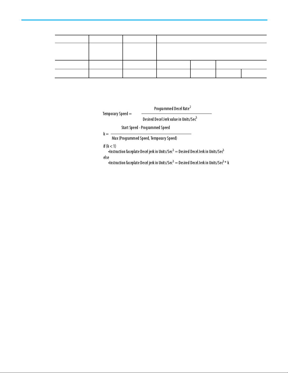
Chapter 3 Program
Profile
ACC/DEC
Motor
Priority of Control
Highest to Lowest
Velocity Profile Effects
Jerk Programming
Type Time Stress
Trapezoidal Fastest Worst Acc/Dec Velocity Position
S-curve 2X Slower Best Jerk Acc/Dec Velocity Position
in Units/Sec3
This table summarizes the differences between profiles.
To specify the jerk in 'Units/sec3' instead of '% of time', adjust the jerk value to
get the programmed value:
Unique program considerations
If programming a move using the ‘% of Time units’, Logix Designer
application computes an:
2
Accel Jerk = a
/v where a = the programmed Accel Rate and v =
programmed Speed.
Therefore, the higher the programmed speed, the lower the computed Jerk.
The system has a Jerk priority planner.
In other words, Jerk has a higher priority than acceleration and velocity.
Therefore, the programmed Jerk is always present. If a move is velocitylimited, the move does not reach the programmed acceleration and/or
velocity.
Once the velocity limit for the length of the move is reached, as the velocity
increases, the move requires more time to complete.
‘Decel Jerk’ is computed similarly to the Accel Jerk described above. The only
2
difference is that instead of a
/v, Decel Jerk = d2/v, where d = the programmed
Decel Rate.
58 Rockwell Automation Publication MOTION-UM001I-EN-P - Septemberr 2020
Page 59

EXAMPLE
Example #1
Instruction faceplate Decel jerk in Units/Sec3 = 1.0 in/sec3
EXAMPLE
Example #2
= 1.6 in/sec3
Profile operand
Trapezoidal velocity profile
Start Speed = 8.0 in/sec
Desired Speed = 5.0 in/sec
Desired Decel Rate = 2.0 in/sec2
Desired Decel Jerk = 1.0 in/sec
Temporary Speed = (Desired Decel Rate)2 / Desired jerk value in
3
Units/Sec
= 4.0 in/sec
k = (8.0 - 5.0) / max(5.0, 4.0) = 3.0 / 5.0 = = 0.6
Because k < 1, enter the desired Decel jerk directly in the faceplate
= 2.02 / 1.0 =
3
Chapter 3 Program
Start Speed = 13.0 in/sec
Desired Speed = 5.0 in/sec
Desired Decel Rate = 2.0 in/sec2
Desired Decel Jerk = 1.0 in/sec
Temporary Speed = (Desired Decel Rate)
= 4.0 in/sec
k = (13.0 - 5.0) / max(5.0, 4.0) = 8.0 / 5.0 = = 1.6
Because k > 1, must calculate the Decel jerk to use on the instruction faceplate as:
Instruction faceplate Decel jerk in Units/Sec
= 1.0 in/sec
3
* 1.6 =
3
2
/ Desired jerk value in Units/Sec3= 2.02 / 1.0 =
3
=
What is the revision?
• 15 or earlier – % of Time is fixed at 100.
• 16 or later – % of Time defaults to 100% of time on projects converted
from earlier versions. For new projects, enter the Jerk value.
The profile operand has two profile types:
• Trapezoidal velocity profile
• S-Curve velocity profile
See also
Choose a profile on page 53
The trapezoidal velocity profile is the most commonly used profile because it
provides the most flexibility in programming subsequent motion and the
fastest acceleration and deceleration times. The change in velocity per unit
time is specified by acceleration and deceleration. Jerk is not a factor for
Rockwell Automation Publication MOTION-UM001I-EN-P - Septemberr 2020 59
Page 60

Chapter 3 Program
S-Curve velocity profile
trapezoidal profiles. Therefore, it is considered infinite and is shown as a
vertical line in the following graph.
S-Curve velocity profiles are most often used when the stress on the
mechanical system and load needs to be minimized. The acceleration and
deceleration time is balanced against the machine stress using two additional
parameters, acceleration jerk and deceleration jerk.
Depending on the Jerk settings, the acceleration profile can be set to:
• Almost pure trapezoidal (fastest and highest stress).
• S-Curve (slowest, lowest stress).
The typical acceleration profile is a trade-off between stress and speed.
The Jerk is specified by the user (in Units/sec3 or as a percentage of
maximum), or it is calculated from the percentage of time. (Percentage of
time is equal to the percentage of ramp time in the acceleration/deceleration
profile):
60 Rockwell Automation Publication MOTION-UM001I-EN-P - Septemberr 2020
Page 61

IMPORTANT
Higher values of the % of Time result in lower values of Jerk Rate Limits and,
Trapezoidal Velocity
S-shaped Velocity Profile with 1< = Jerk
S-shaped Velocity Profile with Jerk = 100% of
Accel/Decel Jerk in
Accel/Decel Jerk in % of
Accel/Decel Jerk in % of
Time
Backward compatibility
Chapter 3 Program
The Jerk of 100% of time produces triangular acceleration and deceleration
profiles.
Very small Jerk rates that are less than 5% of time, produce acceleration and
deceleration profiles close to trapezoidal ones.
therefore, slower profiles. See table for reference.
Units/sec3
Maximum
Profile3
<100% of Time4
∞
NA 0 - 100% NA
0% 1 - 100% 100%
Time5
Calculations are performed when an Axis Move, Change Dynamics, or an MCS
Stop of StopType = Move or Jog is initiated.
3
The example labeled Trapezoidal Accel/Decel Time uses a rectangular acceleration
profile.
4
The example labeled Programmable S-Curve Accel/Decel Time, Acceleration Jerk =
60% of Time uses a trapezoidal acceleration profile.
5
The example labeled S-Curve Accel/Decel Time, Backward Compatibility Setting:
Rockwell Automation Publication MOTION-UM001I-EN-P - Septemberr 2020 61
Acceleration Jerk = 100% of Time uses a triangular acceleration profile.
Page 62

Chapter 3 Program
Enter basic logic
Programmable S-Curve Accel/Decel Time Acceleration Jerk = 60%
of Time
S-Curve Accel/Decel Time, Backward Compatibility Setting:
Acceleration Jerk = 100% of Time
62 Rockwell Automation Publication MOTION-UM001I-EN-P - Septemberr 2020
The controller gives a set of motion control instructions for the axes.
Page 63

Example: Motion
Chapter 3 Program
• Uses the instructions in the same way as other Logix 5000
instructions. Program motion control in these programming
languages.
• Ladder diagram (LD)
• Structured text (ST)
• Sequential function chart (SFC)
• Each motion instruction works on one or more axes.
• Each motion instruction needs a motion control tag. The tag uses a
MOTION_INSTRUCTION data type. The tag stores the instruction
status information.
ATTENTION: Use the tag for the motion control operand of motion instruction only once.
Unintended operation of the control variables may happen if reusing the same motion control
tag in other instructions.
control program
If
Initialize_Pushbutton
The MSO instruction turns on the axis.
If
Home_Pushbutton
The MAH instruction homes the axis.
If
Jog_Pushbutton
The MAJ instruction jogs the axis forward at 8 units/s.
This example of ladder logic homes, jogs, and moves an axis.
= on and the axis = off (
= on and the axis has not been homed (
= on and the axis = on (
My_Axis_X.ServoActionStatus
My_Axis_X.ServoActionStatus
= off) then
My_Axis_X.AxisHomedStatus
= on) then
= off) then
Rockwell Automation Publication MOTION-UM001I-EN-P - Septemberr 2020 63
Page 64
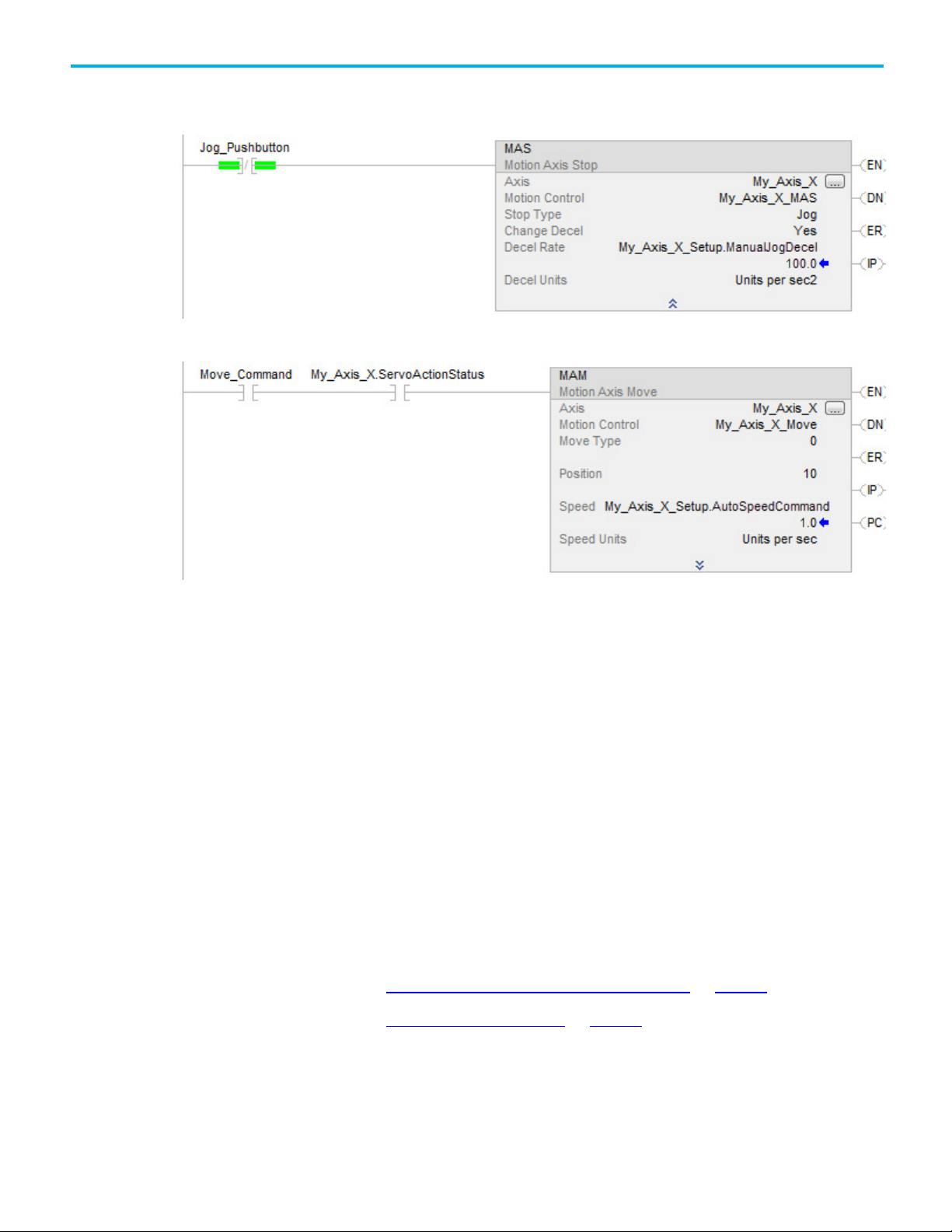
Chapter 3 Program
Download a program
Choose a motion instruction
If
Jog_Pushbutton
The MAS instruction stops the axis at 100 units/s
Make sure that
If
Move_Command
The MAM instruction moves the axis. The axis moves to the position of 10 units at 1 unit/s.
= off then
Change Decel
= on and the axis = on (
is
Yes
. Otherwise, the axis decelerates at its maximum speed.
2
My_Axis_X.ServoActionStatus
= on) then
and run the logic
Use these instructions to download a program to the controller.
To download a program to a controller:
1. With the keyswitch, place the controller in Program or Remote
Program mode.
2. From the Communications menu, select Download.
3. Confirm to complete the download procedure.
4. Select Download.
5. Once the download is complete, place the controller in Run/Test mode.
The status and compiler messages appear in the status bar.
See also
Test an axis with Motion Direct Commands on page 45
Troubleshoot axis motion on page 67
64 Rockwell Automation Publication MOTION-UM001I-EN-P - Septemberr 2020
Use this table to choose an instruction and verify its availability as a Motion
Direct Command.
Page 65

To
And
Use This Instruction
Motion Direct
Enable the drive and set the servo output voltage of
MDO
Yes
Jog an axis.
MAJ
Yes
Move an axis to a position.
MAM
Yes
Start electronic gearing between 2 axes.
MAG
Yes
Change the speed, acceleration, or deceleration of a
MCD
Yes
Motion Calculate Cam Profile
Motion Axis Position Cam
Motion Axis Time Cam
Motion Group Shutdown Reset
Change the state of an axis Enable the drive and activate the axis servo loop. MSO
Motion Servo On
Disable the drive and deactivate the axis servo loop. MSF
Motion Servo Off
Force an axis into the shutdown state and block any
instructions that initiate axis motion.
MASD
Motion Axis Shutdown
Reset the axis from the shutdown state. MASR
Motion Axis Shutdown Reset
Chapter 3 Program
Command
Yes
Yes
Yes
Yes
an axis.
Disable the drive and set the servo output voltage to
the output offset voltage.
Motion Direct Drive On
MDF
Motion Direct Drive Off
Clear all motion faults for an axis. MAFR
Motion Axis Fault Reset
Control axis position Stop any motion process on an axis. MAS
Motion Axis Stop
Home an axis. MAH
Motion Axis Home
Motion Axis Jog
Motion Axis Move
Motion Axis Gear
move or a jog that is in progress.
Define a Master/Slave relationship between two
motion axes and select the type of move instructions.
Motion Change Dynamics
MDAC
Master Driven Axis Control
Change the command or actual position of an axis. MRP
Motion Redefine Position
Calculate a Cam Profile based on an array of cam
MCCP
points.
Start electronic camming between 2 axes. MAPC
Yes
Yes
Yes
Yes
No
Yes
No
No
Initiate action on all axes Stop motion of all axes. MGS
Rockwell Automation Publication MOTION-UM001I-EN-P - Septemberr 2020 65
Start electronic camming as a function of time. MATC
Calculate the slave value, slope, and derivative of the
slope for a cam profile and master value.
MCSV
Motion Calculate Slave Values
Motion Group Stop
Force all axes into the shutdown state. MGSD
Motion Group Shutdown
Transition all axes to the ready state. MGSR
Latch the current command and actual position of all
axes.
MGSP
Motion Group Strobe Position
No
No
Yes
Yes
Yes
Yes
Page 66

Chapter 3 Program
To
And
Use This Instruction
Motion Direct
Motion Disarm Registration
Disarm one or all output cams connected to an axis.
MDOC
No
Tune an axis and run diagnostic tests
Uses the results of an MRAT instruction to calculate
axis.
MAAT
No
Use the results of an MRHD instruction to set encoder
MAHD
No
Change in path dynamics for the active motion on a
MCCD
No
Stop the axes of a coordinate system or cancel a
MCS
No
Shutdown the axes of a coordinate system.
MCSD
No
Sample projects
Arm and disarm special event
checking functions such as
registration and watch position
Arm the watch-position event checking for an axis. MAW
Motion Arm Watch Position
Disarm the watch-position event checking for an
axis.
Arm the servo-module registration-event checking
for an axis.
Disarm the servo-module registration-event checking
MDW
Motion Disarm Watch Position
MAR
Motion Arm Registration
MDR
for an axis.
Arm an output cam for an axis and output. MAOC
Motion Arm Output Cam
Motion Disarm Output Cam
Command
Yes
Yes
Yes
Yes
No
for the control system. These tests
include:
• Motor/encoder hookup test
• Encoder hookup test
• Marker test
Control multi-axis coordinated
motion
and update the servo gains and dynamic limits of an
Motion Apply Axis Tuning
Run a tuning motion profile for an axis. MRAT
Motion Run Axis Tuning
and servo polarities.
Motion Apply Hookup Diagnostic
Run one of the diagnostic tests on an axis. MRHD
Motion Run Hookup Diagnostic
Start a linear coordinated move for the axes of
coordinate system.
Start a circular move for the axes of coordinate
system.
coordinate system.
transform.
MCLM
Motion Coordinated Linear Move
MCCM
Motion Coordinated Circular Move
Motion Coordinated Change Dynamics
Motion Coordinated Stop
Motion Coordinated Shutdown
Start a transform that links two coordinate systems
together. This is like bi-directional gearing.
Calculate the position of one coordinate system with
respect to another coordinate system.
Transition the axes of a coordinate system to the
ready state and clear the axis faults.
Define a Master/Slave relationship between a Master
Axis and a Coordinate System.
MCT
Motion Coordinated Transform
MCTP
Motion Calculate Transform Position
MCSR
Motion Coordinated Shutdown Reset
MDCC
Master Driven Coordinated Control
No
No
No
No
No
6
No
7
No
No
66 Rockwell Automation Publication MOTION-UM001I-EN-P - Septemberr 2020
The Rockwell Automation sample project's default location is:
6
Use this instruction only with 1756-L6x controllers.
7
Use this instruction only with 1756-L6x controllers.
Page 67

Troubleshoot axis motion
Why does my axis
accelerate when I stop it?
Example
Look For
Cause
c:\Users\Public\Public Documents\Studio
5000\Sample\ENU\v<current_release>\Rockwell Automation
A PDF file named Vendor Sample Projects explains how to work with the
sample projects. Free sample code is available at
http://samplecode.rockwellautomation.com/
The Vendor Sample Projects.pdf default location is:
c:\Users\Public\Public Documents\Studio
5000\Sample\ENU\v<current_release>\Third Party Products
Troubleshooting information is provided for situations that may occur while
running an axis.
While an axis is accelerating, you try to stop it. The axis keeps accelerating for
a short time before it starts to decelerate.
You start a Motion Axis Jog (MAJ) instruction. Before the axis gets to its target
speed, you start a Motion Axis Stop (MAS) instruction. The axis continues to
speed up and then eventually slows to a stop.
.
Chapter 3 Program
Rockwell Automation Publication MOTION-UM001I-EN-P - Septemberr 2020 67
When using an S-curve profile, jerk determines the acceleration and
deceleration time of the axis.
• An S-curve profile must get acceleration to 0 before the axis can slow
down.
• The time required depends on the acceleration and speed.
• In the meantime, the axis continues to speed up.
Page 68

Chapter 3 Program
Stop while accelerating
Trapezoidal
S-curve
The axis slows down as soon as you start the stopping instruction. The axis continues to speed up until the S-curve profile brings the acceleration
These trends show how the axis stops with a trapezoidal profile and an Scurve profile.
rate to 0.
68 Rockwell Automation Publication MOTION-UM001I-EN-P - Septemberr 2020
Page 69

Leave bit 0 of the DynamicsConfigurationBits attribute for the axis turned ON.
If the Jerk Units Are
Then Make This Change to the Decel Jerk
% of Time
Reduce the % of Time on the Decel Jerk
% of Maximum
Increase the % of Maximum on the Decel Jerk
Units per sec3
Increase Units per sec3 on the Decel Jerk
Corrective Action
Revision 15 or earlier
Chapter 3 Program
Rockwell Automation Publication MOTION-UM001I-EN-P - Septemberr 2020 69
Revision 16 or later
ATTENTION:
Otherwise, this corrective action will not work.
For more information search for Dynamic Configuration Bits in the Help.
In Revision 16 and later, increase the deceleration jerk of an Motion Action
Stop (MAS) instruction to get a quicker stop.
Page 70

Chapter 3 Program
Why does my axis
Example
Look For
Cause
overshoot its target speed?
While an axis is accelerating, you try to stop the axis or change its speed. The
axis keeps accelerating and goes past its initial target speed. Eventually the
axis starts to decelerate.
You start a Motion Axis Jog (MAJ) instruction. Before the axis gets to its target
speed, you try to stop it with another MAJ instruction. The speed of the
second instruction is set to 0. The axis continues to speed up and overshoots
its initial target speed. Eventually it slows to a stop.
When using an S-curve profile, jerk determines the acceleration and
deceleration time of the axis.
70 Rockwell Automation Publication MOTION-UM001I-EN-P - Septemberr 2020
Page 71

Stop while accelerating and reduce the acceleration rate
The axis slows down as soon as the stopping instruction starts.
The stopping instruction reduces the acceleration of the axis. It now takes
Chapter 3 Program
• An S-curve profile must get acceleration to 0 before the axis can slow
down.
• If reducing the acceleration, more time is required to get acceleration
to 0.
• In the meantime, the axis continues past its initial target speed.
These trends show how the axis stops with a trapezoidal profile and an Scurve profile.
Trapezoidal
The lower acceleration does not change the response of the axis.
S-curve
longer to bring the acceleration rate to 0. The axis continues past its
target speed until acceleration equals 0.
Rockwell Automation Publication MOTION-UM001I-EN-P - Septemberr 2020 71
Page 72

Chapter 3 Program
Corrective Action
Why is there a delay when I
Example
Use a Motion Axis Stop (MAS) instruction to stop the axis or configure the
instructions as shown:
stop and then restart a jog?
72 Rockwell Automation Publication MOTION-UM001I-EN-P - Septemberr 2020
While an axis is jogging at its target speed, you stop the axis. Before the axis
stops completely, you restart the jog. The axis continues to slow down before
it speeds up.
Use a Motion Axis Stop (MAS) instruction to stop a jog. While the axis is
slowing down, use a Motion Axis Jog (MAJ) instruction to start the axis again.
The axis does not respond right away. It continues to slow down. Eventually
the axis speeds back up to the target speed.
Page 73

Start while decelerating
Trapezoidal
S-curve
Look For
Cause
Chapter 3 Program
For Stop Type, the instruction that stops the axis keeps the S-curve profile. If
using a Motion Axis Stop (MAS) instruction with the Stop Type set to Jog, the
axis keeps the profile of the Motion Axis Jog (MAJ) instruction that started the
axis.
When using an S-curve profile, jerk determines the acceleration and
deceleration time of the axis. An S-curve profile has to get acceleration to 0
before the axis can speed up again. These trends show how the axis stops and
starts with a trapezoidal profile and an S-curve profile.
Rockwell Automation Publication MOTION-UM001I-EN-P - Septemberr 2020 73
Page 74
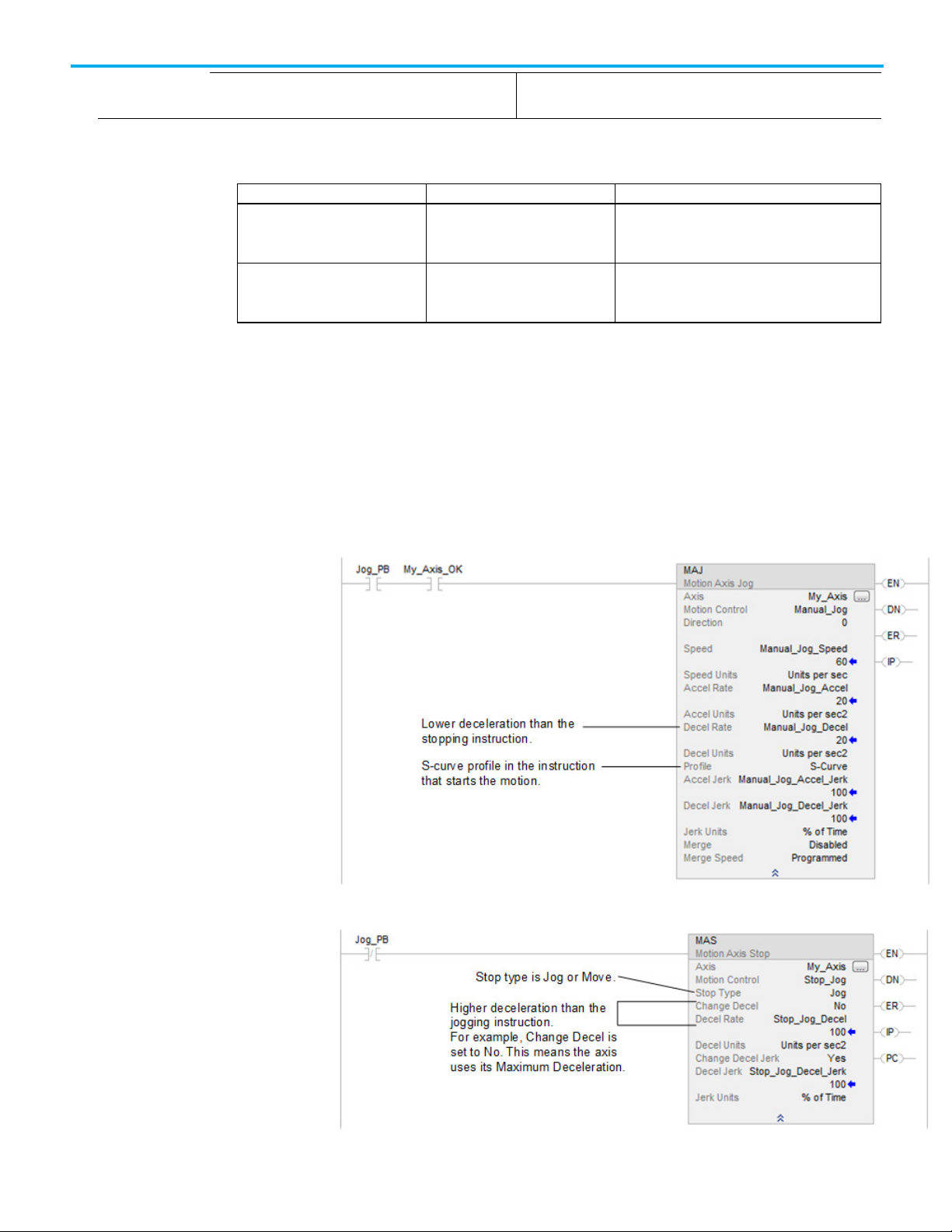
Chapter 3 Program
If the controller revision is
Then
Result
starts the jog.
jerk.
Corrective action
Why does my axis
Example
Look For
The axis speeds back up as soon as you start the jog again. The axis continues to slow down until the S-curve profile brings the
acceleration rate to 0.
The corrective action depends on the revision of the controller.
15 or earlier Increase the deceleration rate of the
16 or later Increase the deceleration jerk of the
overshoot its position and
reverse direction?
This increases the deceleration jerk. The axis stops
Motion Axis Jog (MAJ) instruction that
Motion Axis Jog (MAJ) instruction that
starts the jog.
the deceleration sooner at the higher deceleration
The axis stops the deceleration sooner at the higher
deceleration jerk.
While an axis is moving to a target position, you change a parameter of the
move. The axis overshoots its target position. Eventually the axis stops and
moves back to its target position.
Use a Motion Change Dynamics (MCD) instruction to reduce the deceleration
while a Motion Axis Move (MAM) instruction is in process. The axis continues
past the target position of the move, stops, and returns to the target position.
74 Rockwell Automation Publication MOTION-UM001I-EN-P - Septemberr 2020
Page 75

Cause
Corrective action
Chapter 3 Program
The axis does not have enough time at the new lower deceleration to stop at
the target position. The axis stops past the target position. Then the axis
corrects to get back to the target position.
To avoid overshooting position, do one:
• Avoid decreasing the deceleration or deceleration jerk while an axis is
decelerating along an S-curve profile.
• Avoid increasing the programmed speed while an axis is decelerating
along an S-curve profile. This has the same effect as decreasing the
deceleration jerk.
Test any changes in small increments to make sure a change does not cause an
overshoot during normal operation.
Rockwell Automation Publication MOTION-UM001I-EN-P - Septemberr 2020 75
Page 76

Page 77

IMPORTANT
one or more revolutions to the move distance.
Introduction for
Home an Axis
Chapter 4
Home an axis
Homing puts the equipment at a starting point for operation. This starting
point is called the home position. Typically, equipment is homed when it is
reset for operation.
Three types of homing are:
• Active homing
• Passive homing
• Absolute homing
Active homing
When the axis Homing Mode is configured as Active, the physical axis is first
activated for servo operation. The Home operation does not cancel other
motion, but errors, Err=22.
Home an axis using the configured Home Sequence, which may be
Immediate, Switch, Marker, Switch-Marker, or Torque-Level homing. The
Home Sequences result in the axis being jogged in the configured Home
Direction. Using bidirectional homing, after the position is re-defined based
on detection of the home event, the axis is automatically moved to the
configured Home Position.
When unidirectional active homing is performed on a rotary axis and the Home Offset
value is less than the deceleration distance when the home event is detected, it adds
Passive homing
When the axis Homing Mode is configured as Passive, the MAH instruction
re-defines the actual position of a physical axis on the next occurrence of the
encoder marker, providing that Sequence is set to Marker. Immediate,
Switch, Switch-Marker and Torque Level homing is also allowed.
Rockwell Automation Publication MOTION-UM001I-EN-P - Septemberr 2020 77
Passive homing is most commonly used to calibrate Feedback Only axes to
their markers, but can also be used on Servo axes. Passive homing is identical
to active homing to an encoder marker except that the Home command does
not command any axis motion.
After initiating passive homing, the axis must be moved past the encoder
marker for the homing sequence to complete properly. For closed-loop Servo
Page 78

Chapter 4 Home an axis
IMPORTANT
position.
Guideline
Description
Guidelines for homing
axes, this may be accomplished with a MAM or MAJ instruction. For physical
Feedback Only axes, motion cannot be commanded directly by the motion
controller, and must be accomplished through other means.
Absolute homing
If the motion axis hardware supports an absolute feedback device, consider
using the Absolute Homing Mode. The only Home Sequence for an absolute
Homing Mode is Immediate. In this case, the absolute homing process
establishes the true absolute position of the axis by applying the configured
Home Position, to the reported position of the absolute feedback device.
Before execution of the absolute homing process via the MAH instruction, the
axis must be in the Axis Ready state with the servo loop disabled.
To successfully execute a MAH instruction on an axis configured for Active
homing mode, the targeted axis must be configured as a Servo Axis Type. To
successfully execute an MAH instruction, the targeted axis must be
configured as a Servo or Feedback Only axis. If any of these conditions are not
met, the instruction errors.
When the MAH instruction is initially executed, the In process (.IP) bit is set and the
Process Complete (.PC) bit is cleared.
The MAH instruction execution may take multiple scans to execute because it
requires transmission of multiple messages to the motion module. Thus, the Done
(.DN) bit is not set until after these messages are successfully transmitted.
The .IP bit is cleared and the .PC bit is only set if the final axis position = the Home
This is a transitional instruction:
• In relay ladder, toggle the rung from cleared to set each time the
instruction should execute.
• In structured text, condition the instruction so that it only executes on
a transition.
See also
Motion Axis Attributes on page 147
This table provides homing guidelines and descriptions.
To move an axis to the home position, use Active
homing.
For a Feedback-only device, use Passive homing. Passive homing does not move the axis.
78 Rockwell Automation Publication MOTION-UM001I-EN-P - Septemberr 2020
Active homing turns on the servo loop and moves the axis to the home position. Active homing also:
• Errors if there is any other motion on the axis. Does not stop other motion.
• Uses a trapezoidal profile.
• Use passive homing to calibrate a Feedback-only axis to its marker.
• If using passive homing on a servo axis, turn on the servo loop and use a move instruction to move the axis.
Page 79

Guideline
Description
• For the most precise homing, use the switch and marker.
Sequence
Description
Examples
Chapter 4 Home an axis
If using an absolute feedback device, consider
Absolute homing.
For single-turn equipment, consider homing to a
marker.
For multi-turn equipment, home to a switch or
switch and marker.
If the equipment cannot back up, use
unidirectional homing.
Choose a starting direction for the homing
sequence.
If the motion axis hardware supports an absolute feedback device, Absolute Homing Mode may be used.
The only valid Home Sequence for Absolute Homing Mode is Immediate. In this case, the absolute homing
process establishes the true absolute position of the axis by applying the configured Home Position to the
reported position of the absolute feedback device.
Before execution of the absolute homing process via the MAH instruction, the axis must be in the Axis Ready
state with the servo loop disabled.
The marker homing sequence is useful for single-turn rotary and linear encoder applications because these
applications have only one encoder marker for full axis travel.
These homing sequences use a home limit switch to define the home position.
• Requires a home limit switch if the axis moves multiple revolutions when it runs. Otherwise the controller
cannot tell which marker pulse to use.
With unidirectional homing, the axis does not reverse direction to move to the Home Position. To help insure
that the Home operation is complete, consider using an offset.
If these are not done, the axis position is still correct and accurate.
• Use a Home Offset that is in the same direction as the Home Direction.
• Use a Home Offset that is greater than the deceleration distance.
• If the Home Offset is less than the deceleration distance:
• The axis simply slows to a stop. The axis does not reverse direction to move to the Home Position. In this
case, the MAH instruction does not set the PC bit.
• On a rotary axis, the controller adds 1 or more revolutions to the move distance. This makes sure that the
move to the Home Position is unidirectional.
Which direction should the homing sequence start in?
• Positive direction: Choose a Forward direction.
• Negative direction: Choose a Negative direction.
This table provides active homing examples:
Active homing examples
Active immediate home This sequence sets the axis position to the Home Position without moving the axis. If the axis is not enabled,
this sequence enables it. The feedback is working, therefore enabled.
Rockwell Automation Publication MOTION-UM001I-EN-P - Septemberr 2020 79
Page 80

Chapter 4 Home an axis
Sequence
Description
The mechanical uncertainty of the home limit switch also affects the homing accuracy.
Active home to switch in forward bidirectional The switch homing sequence is useful for multi-turn rotary and linear applications.
Ensure that the home switch is encountered in the direction of the home. If the axis is ON the home limit
switch, the axis can be past the switch, but not on the switch.
These steps occur during the sequence.
1. The axis moves in the Home Direction at the Home Speed to the home limit switch and decelerates to a stop
(using the configured Maximum Deceleration Rate). The axis does not stop immediately.
2. If the axis stopped at the Home Limit Switch, at position 2, when the sequence starts the axis would be at
the home position. The axis reverses direction and moves at the Home Return Speed until it clears the home
limit switch and then stops.
3. The axis moves back to the home limit switch or moves to the Offset position. The axis moves at the Home
Return Speed. If the axis is a Rotary Axis, it moves on the shortest path to the Home Position (no more than
½ revolution).
If the axis is past the home limit switch at the start of the homing sequence, the axis reverses direction and
starts the return leg of the homing sequence. Again, the axis decelerates to a stop.
Use a Home Return Speed that is slower than the Home Speed to increase the homing accuracy. The
accuracy of this sequence depends on the return speed and the delay to detect the transition of the home
limit switch.
Uncertainty = Home Return Speed x delay to detect the home limit switch.
Example: Suppose the Home Return Speed is 0.1 in./s and it takes 10 ms to detect the home limit switch.
Uncertainty = 0.1 in./s x 0.01 s = 0.001 in.
80 Rockwell Automation Publication MOTION-UM001I-EN-P - Septemberr 2020
Page 81

Sequence
Description
Uncertainty = 1 In./s x 0.000001 s = 0.000001 in.
starts the return leg of the homing sequence.
Chapter 4 Home an axis
Active home to marker in forward bidirectional The marker homing sequence is useful for single-turn rotary and linear encoder applications because these
applications have only one encoder marker for full axis travel.
These steps occur during the sequence.
1. The axis moves in the Home Direction at the Home Speed to the marker and decelerates to a stop.
2. The axis moves back to the marker or moves to the Offset position. The axis moves at the Home Return
Speed. If the axis is a Rotary Axis, it moves along the shortest path to the Home Position (no more than ½
revolution).
The accuracy of this homing sequence depends on the homing speed and the delay to detect the marker
transition.
Uncertainty = Home Speed x delay to detect the marker.
Example: Suppose the Home Speed is 1 in./s and it takes 1 µs to detect the marker.
Active home to switch and marker in forward
bidirectional
This is the most precise active homing sequence available.
These steps occur during the sequence.
1. The axis moves in the Home Direction at the Home Speed to the home limit switch and decelerates to a
stop.
2. The axis reverses direction and moves at the Home Return Speed until the axis clears the home limit switch.
3. The axis keeps moving at the Home Return Speed until it gets to the marker.
4. The axis moves back to the marker or moves to the Offset position. The axis moves at the Home Return
Speed. If the axis is a Rotary Axis, it moves along the shortest path to the Home Position (no more than ½
revolution).
If the axis is ON the home limit switch at the start of the homing sequence, the axis reverses direction and
Rockwell Automation Publication MOTION-UM001I-EN-P - Septemberr 2020 81
Page 82

Chapter 4 Home an axis
Sequence
Description
the home position.
Active home to switch in forward unidirectional This active homing sequence is useful when an encoder marker is not available and unidirectional motion is
required or proximity switch is being used.
These steps occur during the sequence:
1. The axis moves in the Home Direction at the Home Speed to the home limit switch.
2. A decel position is calculated using the Home Offset and the decel distance. The axis keeps moving to the
decel position and then decelerates to a stop.
3. The axis moves to the Home Offset position if the axis is in the same direction as the Home Direction.
• When the position mode is linear, the axis decelerates to a stop. May not be at the home position but are
correctly referenced to the home position.
When the position mode is Rotary, the rotary turns as many times that it needs to decelerate and finish at
•
Active home to marker in forward unidirectional This active homing sequence is useful for single-turn rotary and linear encoder applications when
unidirectional motion is required.
These steps occur during the sequence.
1. The axis moves in the Home Direction at the Home Speed to the marker.
2. If the axis is linear, it decelerates to a stop, unless the home offset is greater than the distance required to
decelerate; then the home offset is applied. If the axis is rotary, it adds as many revolutions as necessary so
it decelerates and stops at the home position.
The axis moves to the Home Offset position if it is in the same direction as the Home Direction.
Active home to switch and marker in forward
unidirectional
This active homing sequence is useful for multi-turn rotary applications when unidirectional motion is
required.
These steps occur during the sequence.
1. The axis moves in the Home Direction at the Home Speed to the home limit switch.
2. The axis keeps moving at the Home Speed until it gets to the marker.
3. If the axis is linear, it decelerates to a stop, unless the home offset is greater than the distance required to
decelerate; then the home offset is applied. If the axis is rotary, it adds as many revolutions as necessary so
it decelerates and stops at the home position.
82 Rockwell Automation Publication MOTION-UM001I-EN-P - Septemberr 2020
Page 83

Sequence
Description
Chapter 4 Home an axis
Active Home to Torque The Home to Torque Level sequence is a type of homing used when a hard stop is used as the home position,
as in a linear actuator. The occurrence of the hard stop is detected by the drive when the output torque to the
motor reaches or exceeds the torque level specified by the user. Since the home to torque level sequence
relies on the mechanical end of travel for operation, Unidirectional homing is not possible. Only Forward
Bidirectional and Reverse Bidirectional are allowed.
In Torque Level homing, the torque event is the trigger. The motion planner decelerates the axis to a stop and
reverses direction. The torque event is usually some type of hard stop. Because of this, the physical axis
cannot move, but the position command is changing. This causes the Position error to increase. If the
distance required to decelerate is greater than the Position error Tolerance, an Excessive Position error
exception can occur, possibly canceling the home operation.
A delay filter is implemented in the drive to reduce any false/nuisance triggers when there is a spike in the
torque feedback upon enabling or jogging the motor under load.
Torque Level homing is very similar to Home Switch homing, with the exception that the torque level is used
instead of the home switch input. This graphic depicts the Position/Velocity for Torque Level Homing.
Torque Level-Marker homing is very similar to Home Switch-Marker homing, with the exception that the torque
level is used instead of the home switch input. This graphic depicts the Position/Velocity for Torque LevelMarker Homing.
Rockwell Automation Publication MOTION-UM001I-EN-P - Septemberr 2020 83
Page 84

Chapter 4 Home an axis
Sequence
Description
axis motion.
the switch is hit. Set the Offset value to 0 if no Home Offset offset is wanted.
switch is hit. Set the Offset value to 0 if no Home Offset offset is wanted.
Passive homing examples
Homed Status
Feedback Integrity
This table provides passive homing examples.
Passive Immediate Home This is the simplest passive homing sequence type. When this sequence is performed, the controller
immediately assigns the Home Position to the current axis actual position. This homing sequence produces no
Passive Home with Switch This passive homing sequence is useful when an encoder marker is not available or a proximity switch is
being used.
When this sequence is performed in the Passive Homing Mode, an external agent moves the axis until the
home switch is detected. The position is preset to the Home position plus Offset Value at the moment when
Passive Home with Marker This passive homing sequence is useful for single-turn rotary and linear encoder applications.
When this sequence is performed in the Passive Homing Mode, an external agent moves the axis until the
marker is detected. The position is preset to the Home position plus Offset Value at the moment when the
Passive Home with Switch then Marker This passive homing sequence is useful for multi-turn rotary applications.
When this sequence is performed in the Passive Homing Mode, an external agent moves the axis until the
home switch and then the first encoder marker is detected. The position is preset to the Home position plus
Offset Value at the moment when the switch is hit. Set the Offset value to 0 if no Home Offset offset is wanted.
The Homed Status bit is set by the MAH instruction upon successful
completion of the configured homing sequence. This bit indicates that an
absolute machine reference position was established. When this bit is set,
operations that require a machine reference, such as Software Overtravel
checking, can be meaningfully enabled.
For CIP Drive axis data types, the Homed Status bit clears under this
condition:
• MRP instruction
For non-CIP Drive axis data types, the Homed Status bit is cleared under
these conditions:
• Download
• Control power cycle
• Re-connection to Motion Module
• Feedback Loss Fault
• Shutdown
When set, this bit indicates that the feedback device is accurately reflecting
axis position. The bit is set at power-up assuming that the feedback device
passes any power-up self test required. If during operation, a feedback
exception occurs that could impact the fidelity of axis position, the bit
immediately clears. The bit remains clear until a fault reset is executed by the
drive or the drive is power cycled. The Feedback Integrity bit behavior applies
to absolute and incremental feedback device operation.
84 Rockwell Automation Publication MOTION-UM001I-EN-P - Septemberr 2020
Page 85

Item
Description
Axis Configuration
Selects and displays the intended use of the axis.
The Associated Module selection (selected on the
tab) determines available catalog numbers.
Introduction for Axis
Properties
General tab – AXIS_SERVO
Appendix A
Axis properties
This appendix describes the properties of an axis. For a description of the
Axis_CIP_Drive properties, see
Network Configuration and Startup, publication MOTION-UM003.
This General dialog box shows an AXIS_SERVO data type.
Integrated Motion on the Ethernet/IP
Feedback Only If the axis is used only to display position information from the feedback interface. This
selection minimizes the display of axis properties tabs and parameters. The tabs Servo, Tune,
Dynamics, Gains, Output, Limits, and Offset do not appear.
Servo If the axis is used for full servo operation. This selection maximizes the display of axis
properties tabs and parameters.
Motion Group Selects and displays the Motion Group to which the axis is associated. An axis assigned to a Motion Group appears in
the Motion Groups branch of the Controller Organizer, under the selected Motion Group sub-branch.
Selecting <none> terminates the Motion Group association, and moves the axis to the Ungrouped Axes sub-folder of
the Motion Groups branch.
General
Module Selects and displays the name of the motion module to which the axis is associated. Displays <none> if the axis is not
associated with any motion module.
Module Type Displays a module icon and the name of the SERCOS drive to which the axis is associated. Displays <none> if the axis
is not associated with any drive. If the associated drive is a Kinetix Safety drive, a portion of the module icon is red to
signify its safety significance.
Channel Selects and displays the 1756-M02AE motion module channel, 0 or 1, to which the axis is assigned. Disabled when the
axis is not associated with any motion module.
Rockwell Automation Publication MOTION-UM001I-EN-P - Septemberr 2020 85
Page 86

Appendix A Axis properties
Item
Description
General tab -
This dialog box shows the General tab for an AXIS_SERVO DRIVE data type.
AXIS_SERVO_DRIVE
Axis Configuration Selects and displays the intended use of the axis.
Feedback Only If the axis is used only to display position information from the feedback interface. This
selection minimizes the display of axis properties tabs and parameters. The tabs Tune,
Dynamics, Gains, Output, Limits, and Offset do not appear.
Servo If the axis is used for full servo operation. This selection maximizes the display of axis
properties tabs and parameters.
Motion Group Selects and displays the Motion Group to which the axis is associated. An axis assigned to a Motion Group appears in
the Motion Groups folder of the Controller Organizer, under the selected Motion Group sub-branch.
Selecting <none> terminates the Motion Group association, and moves the axis to the Ungrouped Axes sub-folder of
the Motion Groups folder.
Module Selects and displays the name of the SERCOS drive to which the axis is associated. Displays <none> if the axis is not
associated with any drive.
Module Type Displays a module icon and the name of the SERCOS drive to which the axis is associated. Displays <none> if the axis is
not associated with any drive. If the associated drive is a Kinetix Safety drive, a portion of the module icon is red to
signify its safety significance.
A sample of the module icon (from the I/O configuration folder in Logix Designer application) for:
• Kinetix 6000 Advanced Safety Drive (S1)
• Kinetix 6000 Enhanced Safe Torque-Off Drive (S0)
Node Displays the base node of the associated SERCOS drive. Unavailable when the axis is not associated with any drive.
86 Rockwell Automation Publication MOTION-UM001I-EN-P - Septemberr 2020
Page 87

Node with a
Kinetix 6000 drive
General tab - AXIS_VIRTUAL
Motion Group
MOTION_GROUP structure
If using the auxiliary feedback port of a Kinetix 6000 drive as a feedback-only
axis, the drive must have firmware revision 1.80 or later.
Appendix A Axis properties
When a Kinetix 6000 drive is designated in the Associated Module box, there
is an additional option for the Node value. The option is the node associated
with the drive plus 128 with (Auxiliary) after the number. The range is 129 to
234. When the Auxiliary Node assignment is chosen, the axis configuration is
changed to Feedback Only on the General tab and an asterisk (*) appears next
to General. This also places an asterisk (*) on the Aux Feedback tab. Select that
tab and choose values. On the Drive/Motor tab, the Loop Configuration
changes to Aux Feedback Only.
This image is an example of the General tab for an AXIS_VIRTUAL Data Type.
Select the Motion Group to which the axis is associated. An axis assigned to a
Motion Group appears in the Motion Groups folder of the Controller
Organizer. Selecting ‘none’ terminates the Motion Group association, and
moves the axis to the Ungrouped Axes folder in the Controller Organizer.
Rockwell Automation Publication MOTION-UM001I-EN-P - Septemberr 2020 87
One MOTION_GROUP data type per controller. This structure contains status
and configuration information about the motion group.
Page 88

Appendix A Axis properties
Enumerations
Data Type
Description
Bit
Number
Data Type
Description
InhibitStatus
00
DINT
Inhibit status.
GroupSynced
01
DINT
Synchronization status.
-no-tag
02
DINT
Timer Event started.
Reserved
03…31
Bit
Number
Data Type
Description
ACSyncConnFault
01
DINT
Synchronous connection fault.
Bit
Number
Data Type
Description
POtrvlFault
00
DINT
Positive overtravel fault.
PosErrorFault
02
DINT
Position error fault.
EncCHALossFault
03
DINT
Encoder channel A loss fault.
EncCHBLossFault
04
DINT
Encoder channel B loss fault.
EncCHZLossFault
05
DINT
Encoder channel Z loss fault.
EncNsFault
06
DINT
Encoder noise fault.
Bit
Number
Data Type
Description
SyncConnFault
00
DINT
Synchronous connection fault.
HardFault
01
DINT
Servo hardware fault.
GroupFault
DINT
The fault bits for the group.
Bit
Number
Data Type
Description
GroupOverlapFault
00
DINT
Group task overlap fault.
CST master.
execute.
PhysicalAxisFault
00
DINT
A Servo or Drive fault occurred.
module.
corresponding attribute of the local controller.
GroupStatus DINT The status bits for the group.
AxisInhibitStatus 02 DINT
MotionFault DINT The motion fault bits for the group.
ACAsyncConnFault 00 DINT Asynchronous connection fault.
Reserved 02…31
ServoFault DINT The servo-module fault bits for the group.
NOtrvlFault 01 DINT Negative overtravel fault.
DriveFault 07 DINT Drive fault.
Reserved 08…31
Reserved 02…31
CSTLossFault 01 DINT The controller has lost synchronization with the
AxisFault DINT The fault bits for the axis.
88 Rockwell Automation Publication MOTION-UM001I-EN-P - Septemberr 2020
GroupTaskLoadingFault 02 DINT The group base update period is too low, user
application tasks are not getting enough time to
Reserved 03…31
Bit Number Data Type Description
ModuleFault 01 DINT A serious fault occurred with the motion module
associated with the selected axis. Usually
affects all axes associated with the motion
ConfigFault 02 DINT One or more axis attributes associated with a
motion module or drive was not successfully
updated to match the value of the
Page 89

Enumerations
Data Type
Description
Item
Description
General tab – AXIS_GENERIC
Motion Planner tab
Appendix A Axis properties
Reserved 03…31
This example shows the General tab for an AXIS_GENERIC data type.
Axis Configuration Selects and displays the intended use of the axis.
Feedback Only If the axis is used only to display position information from the feedback interface. This selection
minimizes the display of axis properties tabs and parameters. The Dynamics tab is not available.
Servo If the axis is used for full servo operation. This selection maximizes the display of axis properties tabs and
parameters.
Motion Group Selects and displays the Motion Group to which the axis is associated. An axis assigned to a Motion Group appears in the Motion
Groups folder of the Controller Organizer, under the selected Motion Group sub-folder. Selecting <none> terminates the Motion
Group association, and moves the axis to the Ungrouped Axes sub-folder of the Motion Groups branch.
Module Selects and displays the name of the motion module to which the axis is associated. Displays <none> if the axis is not
associated with any motion module.
Channel Selects and displays the motion module channel, 0 or 1, to which the axis is assigned. Disabled when the axis is not associated
with any motion module.
Use the Motion Planner tab options to:
• Set and edit the number of Output Cam Execution Targets and the
Program Stop Action
• Select and clear the Master Delay Compensation and Enable Master
Position Filter
• Set the bandwidth for Master Position Filter Bandwidth
The Motion Planner tab has the same fields regardless of the type of axis.
Rockwell Automation Publication MOTION-UM001I-EN-P - Septemberr 2020 89
Page 90

Appendix A Axis properties
Item
Description
Enable Master Position Filter
Enables or disables the Master Position Filter. The default is disabled. Select to enable position filtering.
When this feature is enabled the Master Position Filter Bandwidth field is enabled.
Output Cam Execution
Targets
Determines how many Output Cam execution nodes (instances) to create for an axis.
The Execution Target parameter for the MAOC/MDOC instructions specifies which of the configured execution nodes the
instruction affects. In addition, the number specified in the Axis Properties dialog box specifies the number of instances of
Output Cam in which the value of zero means ‘none’. The value specified for Execution Target in the MAOC instruction references
an instance in which a value of zero selects the first instance.
Program Stop Action Selects how an axis is stopped when the processor undergoes a mode change, or when an explicit Motion Group Programmed
Stop (MGPS) instruction is executed. Apply Program Stop Action when an MSG is programmed to Stop type.
Fast Disable The axis is decelerated to a stop using the current configured value for maximum deceleration. Servo
action is maintained until the axis motion has stopped, at which time the axis is turned off (that is,
Drive Enable is disabled, and Servo Action is disabled).
Fast Shutdown The axis is decelerated to a stop using the current configured value for maximum deceleration. Once
the axis motion has stopped, the axis is placed in the shutdown state (that is, Drive Enable is
disabled, Servo Action is disabled, and the OK contact is opened). To recover from this state, execute
a Shutdown reset instruction.
Fast Stop The axis is decelerated to a stop using the current configured value for maximum deceleration. Servo
action is maintained after the axis motion has stopped. This mode is useful for gravity or loaded
systems, where servo control is needed at all times.
Hard Disable The axis is immediately disabled (that is, Drive Enable is disabled, Servo Action is disabled, but the
OK contact is left closed). Unless the drive is configured to provide some form of dynamic breaking,
this results in the axis coasting to a stop.
Hard Shutdown The axis is immediately placed in the shutdown state. Unless the drive is configured to provide some
form of dynamic breaking, this results in the axis coasting to a stop. To recover from this state, a
Shutdown reset instruction must be executed.
Master Delay Compensation Enables or disables Master Delay Compensation. The default setting is Disabled. Select to enable Master Delay Compensation.
Master Delay Compensation balances the delay time between reading the master axis command position and applying the
associated slave command position to the slave’s servo loop. It ensures that the slave axis command position accurately tracks
the actual position of the master axis; that is, zero tracking error.
If the axis is configured for Feedback only, disable Master Delay Compensation.
Master Position Filter effectively filters the specified master axis position input to the slave axis’s gearing or position camming
operation. The filter smooths out the actual position signal from the master axis, and thus smooths out the corresponding
motion of the slave axis.
Master Position Filter
Bandwidth
Enabled when Enable Master Position Filter is selected. This field controls the bandwidth for master position filtering. Enter a
value in Hz to set the bandwidth for the Master Position Filter.
Important: A value of zero for Master Position Filter Bandwidth effectively disables the master position filtering.
90 Rockwell Automation Publication MOTION-UM001I-EN-P - Septemberr 2020
Page 91

Item
Description
Item
Description
Loop Configuration
Select the configuration of the servo loop. For this release, only
is available.
Units tab
Servo tab - AXIS_SERVO
Appendix A Axis properties
The Units tab is the same for all axis data types. Use this tab to determine the
units to define the motion axis.
Position Units User-defined engineering units (rather than feedback counts) used for labeling all motion-related values, for example, position
and velocity. These position units can differ for each axis.
Choose position units for maximum ease of use in the application. For example, linear axes might use position units of Inches,
Meters, or mm whereas rotary axes might use units of Revs or Degrees.
Average Velocity Timebase Specifies the time (in seconds) used for calculating the average velocity of the axis. This value is computed by taking the total
distance the axis travels in the amount of time specified and dividing this value by the timebase.
The average velocity timebase value should be large enough to filter out the small changes in velocity that result in a noisy
velocity value, but small enough to track significant changes in axis velocity. A value of 0.25 to 0.50 seconds works well for
most applications.
This image is an example of the Servo tab for AXIS_SERVO.
External Drive Configuration Select the drive type for the servo loop:
• Velocity - Disables the servo module’s internal digital velocity loop.
• Torque - The servo module’s internal digital velocity loop is active, which is the required configuration for
interfacing the servo axis to a torque loop drive.
• Hydraulic - Enables hydraulic servo application features.
Position Servo
Enable Drive Fault Input Select to enable the Drive Fault Input. When active, the motion module receives notice whenever the external
Rockwell Automation Publication MOTION-UM001I-EN-P - Septemberr 2020 91
drive detects a fault.
Page 92

Appendix A Axis properties
Item
Description
Attribute 1/Attribute 2
Select up to two axis attributes whose statuses are transmitted with, for example, the actual position data to the
Item
Description
Feedback tab – AXIS_SERVO
Drive Fault Input Specifies the usual state of the drive fault input when a fault is detected on the drive.
Enable Direct Drive Ramp Control Select to set the Direct Drive Ramp Rate in volts per second when a Direct Drive On (MDO) instruction is executed.
Direct Drive Ramp Rate The Direct Drive Ramp Rate is a slew rate for changing the output voltage when an MDO instruction is executed. A
• Normally Open – When a drive fault is detected, it opens its drive fault output contacts.
• Normally Closed – When a drive fault is detected, it closes its drive fault output contacts.
Direct Drive Ramp Rate of 0 disables the output rate limiter, letting the Direct Drive On voltage be applied directly.
Logix processor. Access the values of the selected attributes through the standard GSV or Get Attribute List
service. Can also access the values using template data.
The servo status data is updated each base update period.
If a GSV is done to one of these servo status attributes without having selected this attribute through the Drive
Info Select attribute, the attribute value is static and does not reflect the true value in the servo module.
Use the Feedback tab to select the type of Feedback used with the Servo axis.
Feedback Type Select the Feedback type for the current configuration. The options depend on the motion module to which the axis is
associated.
A Quadrature B Encoder Interface (AQB) The 1756-M02AE servo module provides interface hardware to support incremental
quadrature encoders equipped with standard 5-Volt differential encoder-interface
signals. The AQB option has no associated attributes to configure.
Synchronous Serial Interface (SSI) The 1756-M02AS servo module provides an interface to transducers with
Synchronous Serial Interface (SSI) outputs. SSI outputs use standard 5V differential
signals (RS422) to transmit information from the transducer to the controller. The
signals consist of a Clock generated by the controller and Data generated by the
transducer.
Linear Displacement Transducer (LDT) The 1756-HYD02 Servo module provides an interface to the Linear Magnetostrictive
Displacement Transducer, or LDT. A Field Programmable Gate Array (FPGA) is used
to implement a multi-channel LDT Interface. Each channel is functionally
equivalent and is capable of interfacing to an LDT device with a maximum count of
240,000. The LDT interface has transducer failure detection and digital filtering to
reduce electrical noise.
92 Rockwell Automation Publication MOTION-UM001I-EN-P - Septemberr 2020
Page 93

Item
Description
Clock Frequency
Sets the clock frequency of the SSI device to 208 (default) or 625 kHz. When the higher clock frequency is used, the data from
frequency.
powerup.
Appendix A Axis properties
Feedback Type Feedback Type is set to SSI - Synchronous Serial Interface.
Code Type The type of code, Binary or Gray, used to report SSI output. If the module’s setting does not match the feedback device, the
positions jump around erratically as the axis moves.
Data Length The length of output data in a specified number of bits between 8 and 31. The data length for the selected feedback device is
found in its specifications.
Enable Absolute
Feedback
Absolute Feedback
Offset
the feedback device is more recent, but the length of the cable to the transducer must be shorter than with the lower
The default is enabled (checked). If Enable Absolute Feedback is set, the servo module adds the Absolute Feedback Offset to
the current position of the feedback device to establish the absolute machine reference position. Absolute feedback devices
retain their position reference even through a power-cycle; therefore, the machine reference system can be restored at
If Absolute feedback is enabled, this field becomes active. Enter the amount of offset, in position units, to add to the current
position of the Feedback device.
The SSI is an absolute feedback device. To establish a value for the Offset, execute the MAH instruction with the Home Mode
set to Absolute. When executed, the module computes the Absolute Feedback Offset as the difference between the
configured value for Home Position and the current absolute feedback position of the axis. The computed Absolute Feedback
Offset is immediately applied to the axis upon completion of the MAH instruction. The actual position of the axis is rereferenced during execution of the MAH instruction; therefore, the servo loop must not be active. If the servo loop is active,
the MAH instruction generates an error.
When the Enable Absolute Feedback is disabled, the servo module ignores the Absolute Feedback Offset and treats the
feedback device as an incremental position transducer. A homing or redefine position operation is required to establish the
absolute machine reference position. The Absolute Home Mode is invalid.
If using single-turn or multi-turn Absolute SSI Feedback transducers, see the Homing tab information for important details
concerning Absolute feedback transducer’s marker reference.
Rockwell Automation Publication MOTION-UM001I-EN-P - Septemberr 2020 93
Page 94

Appendix A Axis properties
Item
Description
Length
Defines the stroke of travel of the hydraulic cylinder. The length value is used with the number of recirculations to
Scaling
Defines the relationship between the LDT unit of measure (length field) and the unit of measure defined at the Units tab.
Minimum Servo
The Minimum Servo Update period is calculated based on the values entered for Recirculations and
Feedback Type Feedback Type is set to LDT - Linear Displacement Transducer.
LDT Type Selects the type of LDT to use to provide feedback to the Hydraulic module. The available types are PWM, Start/Stop
Recirculations Use this field to set the number of repetitions to use to acquire a measurement from an LDT.
Rising, or Start/Stop Falling.
Calibration Constant Number engraved on the LDT by the manufacturer. The number specifies the characteristics of the individual LDT. Each
LDT has its own calibration constant; therefore, changing the LDT also requires changing the Calibration constant.
determine the minimum servo update period.
Enable Absolute Feedback Active only when Feedback Type is LDT.
Absolute Feedback Offset Enter the amount of offset, in position units, to add to the current position of the LDT.
The LDT is an absolute feedback device. To establish a value for the Offset, execute the MAH instruction with the Home
Mode set to Absolute. When executed, the module computes the Absolute Feedback Offset as the difference between the
configured value for Home Position and the current absolute feedback position of the axis. The computed Absolute
Feedback Offset is immediately applied to the axis upon completion of the MAH instruction. The actual position of the axis
is re-referenced during execution of the MAH instruction; therefore, the servo loop must not be active. If the servo loop is
active, the MAH instruction generates an error.
When the Enable Absolute Feedback is disabled, the servo module ignores the Absolute Feedback Offset and treats the
feedback device as an incremental position transducer. A homing or redefine position operation is required to establish
the absolute machine reference position. The Absolute Home Mode is invalid.
Calculated Values Conversion
Constant
The Conversion Constant is calculated from the values entered on the Feedback screen when
selecting Calculate. This calculated value must be typed into the Conversion Constant field on the
Conversion tab because the value is not automatically updated.
Update Period
Length on the Feedback tab. When these values are changed, clicking Calculate recalculates the
Minimum Servo Update Period based on the new values.
Calculate Button Calculate becomes active whenever making changes to the values on the Feedback tab. Selecting
Calculate recalculates the Conversion Constant and Minimum Servo Update Period values. Reenter the Conversion Constant value at the Conversion tab because the values are not updated
automatically.
94 Rockwell Automation Publication MOTION-UM001I-EN-P - Septemberr 2020
Page 95

Item
Description
controller recalculates the values.
Drive Counts per
Choose the units to use for this drive. Options are Motor Inch, Motor Millimeter, and Motor Rev (default).
Drive/Motor tab -
AXIS_SERVO_DRIVE
Amplifier Catalog Number Select the catalog number of the amplifier to which this axis is connected.
Motor Catalog Number Select the catalog number of the motor associated with this axis. When changing a Motor Catalog Number, the
Appendix A Axis properties
Use the Drive/Motor tab to configure the servo loop for an
AXIS_SERVO_DRIVE axis, and open the Change Catalog dialog box.
Change Catalog Opens the Change Catalog Number dialog box to select a new motor catalog number.
Loop Configuration Select the configuration of the servo loop.
• Motor Feedback Only – Displayed when Axis Configuration is Feedback only
• Aux Feedback Only – Displayed when Axis Configuration is Feedback only
• Position Servo
• Aux Position Servo (not applicable to Ultra3000 drives)
• Dual Position Servo
• Dual Command Servo
• Aux Dual Command Servo
• Velocity Servo
• Torque Servo
• Dual Command/Feedback Servo
Drive Resolution Type the number of counts per motor revolution. This value applies to all position data. Valid values range from 1 to
2^32 - 1. One Least Significant Bit (LSB) for position data equals 360° / RotationalPositionResolution.
The Drive Resolution is also referred to as Rotational Position Resolution.
When saving an edited Conversion Constant or a Drive Resolution value, a message box opens, asking if the
controller should automatically recalculate certain attribute settings.
Drive Resolution is especially helpful for fractional unwind applications or multi-turn applications requiring cyclic
compensation. Modify the Drive Resolution value so that dividing it by the Unwind Value yields a whole integer
value. The higher the Drive Resolution setting, the finer the resolution.
Calculate Opens the Calculate Position Parameters dialog box to calculate Drive Resolution and Conversion Constant values
based on specific Position Unit Scaling and Position Range information.
Drive Enable Input Checking Select to enable Drive Enable Input Checking. When enabled, the drive regularly monitors the state of the Drive
Enable Input. This dedicated input enables the drive's power structure and servo loop. If cleared, no checking of the
Drive Enable Input occurs.
Drive Enable Input Fault Select to activate the Drive Enable Input Fault. When active, a fault detected on the external drive notifies the
motion module via Drive Fault Input.
Rockwell Automation Publication MOTION-UM001I-EN-P - Septemberr 2020 95
Page 96

Appendix A Axis properties
If the AXIS_SERVO_DRIVE is associated with a
Kinetix Advanced Safety Drive, and
Then
Attribute 1 or Attribute 2 is not populated as Guard
Attribute 2 is populated as Guard Status.
Guard Status, and Attribute 1 is undefined
attribute other than Guard Status
On this tab
These attributes are recalculated
Velocity Proportional Gains
Real Time Axis Information
Attribute 1/Attribute 2
Select up to two axis attributes whose statuses are transmitted – along with the actual position data – to the Logix
processor. Access the values of the selected attributes using a GSV command or from the axis tag itself. This data
is transmitted at a rate equal to the servo status data update time.
If issuing a GSV command for servo status attribute, or using the value from the axis tag, without selecting this
attribute via the Drive Info Select attribute, the attribute value is static and does not reflect the true value in the
servo module.
If the AXIS_SERVO_DRIVE is associated with a Kinetix Enhanced Safe Torque-Off or Advanced Safety Drive, these
two additional Real Time Axis attributes are available.
• Guard Status
• Guard Faults
If an AXIS_SERVO_DRIVE is associated with a Kinetix Advanced Safety Drive, we recommend configuring the Guard
Status attribute. Otherwise, a warning appears when verifying the project.
Attribute 1 or Attribute 2 is populated as Guard Status No action is taken.
Status
Attribute 2 is populated with an attribute other than
Attribute 1 is populated as Guard Status.
Attribute 1 and Attribute 2 are populated with an
Recalculations based on Motor Catalog Number
When the Motor Catalog Number changes on the Drive/Motor tab, the
controller recalculates these values.
Motor Feedback tab Motor Feedback Type
Motor Feedback Resolution
Gains tab Position Proportional Gains
Dynamics tab Maximum Speed
Maximum Acceleration
Maximum Deceleration
Limits tab Position Error Tolerance
Custom Stop Action Attributes
dialog box
Custom Limit Attributes dialog
box
Stopping Torque
Velocity Limit
Bipolar Velocity Limit
Positive Velocity Limit
Negative Acceleration Limit
Bipolar Acceleration Limit
Positive Acceleration Limit
Negative Torque Limit
Bipolar Torque Limit
Positive Torque Limit
Upon project verification, a warning is issued.
Tune Bandwidth dialog box Position Loop Bandwidth
96 Rockwell Automation Publication MOTION-UM001I-EN-P - Septemberr 2020
Velocity Loop Bandwidth
Page 97

Item
Description
Change Catalog Number
Appendix A Axis properties
See also
Conversion Constant on page 147
Change Catalog Number on page 97
Calculate Position Parameters on page 97
Use the Change Catalog Number dialog box to select the catalog number of
the module used in the project.
Catalog Number Lists the available catalog numbers based on the selection criteria from the fields in the Filters area.
Filters Three optional fields refine the search of the Motor Database.
Calculate Position Parameters
Voltage Narrows the search to a voltage rating. The default is all.
Family Narrows the search to a family of motors. The default is all.
Feedback Type Narrows the search to a feedback type. The default is all.
See also
Drive/Motor tab - AXIS_SERVO_DRIVE on page 95
Use the Calculate Position Parameters dialog box to calculate drive resolution
and conversion constant values based on specific position unit scaling and
position range information.
Rockwell Automation Publication MOTION-UM001I-EN-P - Septemberr 2020 97
Page 98

Appendix A Axis properties
Position Mode set to Linear
Position Mode set to Rotary
Item
Description
defined on the Units tab and the units selected to measure position.
Motor Millimeter, or Motor Rev.
Position Range
Maximum travel limit that the system can go.
unwinds in position units per unwind cycle.
values entered for the Position Unit Scaling and Position Range.
Calculate
Select to calculate the Drive Resolution and Conversion Constant values.
dialog box.
The parameters available on dialog box depend on the Position Mode setting
on the Conversion tab.
Position Unit Scaling Position Unit Scaling defines the relationship between the Position Units
per The units used for Position Unit Scaling. The options are: Motor Inch,
Position Unit Unwind For Rotary applications, enter the value for the maximum number of
Calculate Parameters The Calculate Parameters shows the values to calculate based upon the
Drive Resolution Recalculates the resolution based upon the new values entered on this
Conversion Constant Recalculates the Conversion Constant based upon the new values
entered on this dialog box. When editing the setting for the Conversion
Constant or the Drive Resolution, selecting OK or Apply, choose whether
to also recalculate the settings for these dependent attributes.
The attributes are recalculated.
On the Dynamics tab:
• Maximum Velocity
• Maximum Acceleration
• Maximum Deceleration
On the Limits tab:
• Position Error Tolerance
On the Custom Drive Scaling Attributes dialog box:
• Torque Data Scaling
On the Custom Limit Attributes dialog box:
• Velocity Limit Bipolar
• Velocity Limit Positive
• Velocity Limit Negative
• Acceleration Limit Bipolar
• Acceleration Limit Positive
• Acceleration Limit Negative
Position Unwind Recalculates the Position Unwind based upon the new values entered on
this dialog box.
98 Rockwell Automation Publication MOTION-UM001I-EN-P - Septemberr 2020
Page 99

Item
Description
Item
Description
Motor Feedback tab -
AXIS_SERVO_DRIVE
Aux Feedback tab -
Appendix A Axis properties
See also
Drive/Motor tab - (AXIS_SERVO_DRIVE) on page 95
Use the Motor Feedback tab to configure motor and auxiliary feedback device
(if any) parameters for an axis of the type AXIS_SERVO_DRIVE.
The Axis Configuration selection made on the General tab, and the Loop
Configuration selection made on the Drive tab determine which sections of
this dialog box – Motor and Auxiliary Feedback – are enabled.
Feedback Type This field displays the type of feedback associated with the selected motor.
Cycles The number of cycles of the associated feedback device. This helps the Drive Compute Conversion constant used to convert
drive units to feedback counts. Depending on the feedback type selected, this value may be read-only or editable.
Per The units used to measure the cycles.
Interpolation Factor This field displays a fixed, read-only value for each feedback type. This value is used to compute the resolution of the feedback
device.
Feedback Resolution Provides the drive with the resolution of the associated feedback device in cycles.
The Aux Feedback tab is enabled only if on the Driver tab, the Loop
AXIS_SERVO_DRIVE
Configuration field is set to Aux Feedback Only, Aux Position Servo, Dual
Position Servo, Dual Command Servo, or Aux Dual Command Servo. Use this
tab to configure motor and auxiliary feedback device parameters for an axis of
the type AXIS_SERVO_DRIVE.
Feedback Type For applications that use auxiliary feedback devices, choose the type of auxiliary feedback device type. These are drive
Rockwell Automation Publication MOTION-UM001I-EN-P - Septemberr 2020 99
dependent.
Page 100

Appendix A Axis properties
Item
Description
Item
Description
Conversion tab
Cycles The number of cycles of the auxiliary feedback device. This helps the Drive Compute Conversion constant used to convert
drive units to feedback counts. Depending on the feedback type selected, this value may be read-only or editable.
Per The units used to measure the cycles.
Interpolation Factor Displays a fixed constant value for the selected feedback type. This value is used to compute the resolution of the feedback
device.
Feedback Resolution Provides the drive with the resolution of the associated feedback device in cycles.
Feedback Ratio Represents the quantitative relationship between the auxiliary feedback device and the motor. Select the Conversion tab to
access the Axis Properties Conversion dialog box.
Use the Conversion tab to view and edit the Positioning Mode, Conversion
Constant, and if configured as Rotary, the Position Unwind values for an
axis, of the tag types AXIS_SERVO, AXIS_SERVO_DRIVE and
AXIS_VIRTUAL.
The differences in the appearance of the Conversion tab for the AXIS_SERVO
and AXIS_SERVO_DRIVE are the default values for Conversion Constant and
Position Unwind and the labels for these values.
Positioning Mode This parameter is not editable for an axis of the data type AXIS_CONSUMED. Instead, this value is taken from a producing
axis in a networked Logix processor. This value can be edited for AXIS_SERVO, AXIS_SERVO_DRIVE and AXIS_VIRTUAL.
Linear Provides a maximum total linear travel of 2.14 (231) billion feedback counts. With this mode,
the unwind feature is disabled and allows limiting the linear travel distance of the axis by
specifying the positive and negative travel limits for the axis.
Rotary Enables the rotary unwind capability of the axis. This feature provides infinite position
range by unwinding the axis position whenever the axis moves through a complete unwind
distance. The number of encoder counts per unwind of the axis is specified in the Position
Unwind field.
100 Rockwell Automation Publication MOTION-UM001I-EN-P - Septemberr 2020
 Loading...