

Page 1

Assembly Connections for POINT I/O
and ArmorPOINT I/O EtherNet/IP
Adapters
Catalog Numbers Bulletins 1734 and 1738
User Manual
Page 2
Important User Information
WARNING
IMPORTANT
ATTENTION
SHOCK HAZARD
BURN HAZARD
Solid state equipment has operational characteristics differing from those of electromechanical equipment. Safety Guidelines for the Application,
Installation and Maintenance of Solid State Controls (publication SGI-1.1
http://literature.rockwellautomation.com
) describes some important differences between solid state equipment and hard-wired electromechanical
devices. Because of this difference, and also because of the wide variety of uses for solid state equipment, all persons responsible for applying this
equipment must satisfy themselves that each intended application of this equipment is acceptable.
In no event will Rockwell Automation, Inc. be responsible or liable for indirect or consequential damages resulting from the use or application of this
equipment.
The examples and diagrams in this manual are included solely for illustrative purposes. Because of the many variables and requirements associated
with any particular installation, Rockwell Automation, Inc. cannot assume responsibility or liability for actual use based on the examples and
diagrams.
No patent liability is assumed by Rockwell Automation, Inc. with respect to use of information, circuits, equipment, or software described in this
manual.
Reproduction of the contents of this manual, in whole or in part, without written permission of Rockwell Automation, Inc., is prohibited.
Throughout this manual, when necessary, we use notes to make you aware of safety considerations.
available from your local Rockwell Automation sales office or online at
Identifies information about practices or circumstances that can cause an explosion in a hazardous environment, which may
lead to personal injury or death, property damage, or economic loss.
Identifies information that is critical for successful application and understanding of the product.
Identifies information about practices or circumstances that can lead to: personal injury or death, property damage, or
economic loss. Attentions help you identify a hazard, avoid a hazard, and recognize the consequence.
Labels may be on or inside the equipment, such as a drive or motor, to alert people that dangerous voltage may be present.
Labels may be on or inside the equipment, such as a drive or motor, to alert people that surfaces may reach dangerous
temperatures.
Allen-Bradley, Rockwell Automation, POINT I/O, ArmorPOINT I/O, RSView, RSLinx, RSLogix 5000 and TechConnect are trademarks of Rockwell Automation, Inc.
Trademarks not belonging to Rockwell Automation are property of their respective companies.
Page 3

Table of Contents Preface
Why Read This Manual . . . . . . . . . . . . . . . . . . . . . . . . . . . . . . . . . . . . . . v
Who Should Use This Manual. . . . . . . . . . . . . . . . . . . . . . . . . . . . . . . . . v
About the Vocabulary . . . . . . . . . . . . . . . . . . . . . . . . . . . . . . . . . . . . . . . v
Related Documentation. . . . . . . . . . . . . . . . . . . . . . . . . . . . . . . . . . . v
Common Techniques Used in this Manual. . . . . . . . . . . . . . . . . . . . . . vi
Chapter 1
Introduction
About Assembly Connections. . . . . . . . . . . . . . . . . . . . . . . . . . . . . . . . . 1
Choose a Connection. . . . . . . . . . . . . . . . . . . . . . . . . . . . . . . . . . . . . . . . 1
Data Headers . . . . . . . . . . . . . . . . . . . . . . . . . . . . . . . . . . . . . . . . . . . 2
Listen Only Connections. . . . . . . . . . . . . . . . . . . . . . . . . . . . . . . . . . 2
Connection Points . . . . . . . . . . . . . . . . . . . . . . . . . . . . . . . . . . . . . . . 2
Chapter 2
Configuration
About This Chapter . . . . . . . . . . . . . . . . . . . . . . . . . . . . . . . . . . . . . . . . . 5
Configure the Connection. . . . . . . . . . . . . . . . . . . . . . . . . . . . . . . . . 5
Chassis Size . . . . . . . . . . . . . . . . . . . . . . . . . . . . . . . . . . . . . . . . . . . . 5
Data Alignment . . . . . . . . . . . . . . . . . . . . . . . . . . . . . . . . . . . . . . . . . 6
Individual Module Configuration Options. . . . . . . . . . . . . . . . . . . . 7
Module Configuration Sent with the Connection Request . . . . . . . 8
Module Configuration with RSNetWorx for DeviceNet. . . . . . . . . 8
Calculate the Connection Size . . . . . . . . . . . . . . . . . . . . . . . . . . . . . . . . . 9
Connection Size Calculation Example . . . . . . . . . . . . . . . . . . . . . . . 9
Troubleshooting Connection Size Errors. . . . . . . . . . . . . . . . . . . . 10
Table of Contents
Using an Assembly Connection
Assembly Structure
1734/1738 I/O Module Assembly
Information
Chapter 3
Use an Assembly Connection with RSNetWorx for EtherNet/IP . . . 13
Use an Assembly Connection with RSLogix5000 . . . . . . . . . . . . . . . . 16
Add the Hardware to the I/O Configuration Tree . . . . . . . . . . . . 17
Enter the Connection Parameters. . . . . . . . . . . . . . . . . . . . . . . . . . 18
Build the Configuration Tag . . . . . . . . . . . . . . . . . . . . . . . . . . . . . . 18
Chapter 4
Assembly Structure Examples . . . . . . . . . . . . . . . . . . . . . . . . . . . . . . . . 23
Byte, Word, and Double Word Alignment. . . . . . . . . . . . . . . . . . . 23
Fixed Size per Slot Alignment. . . . . . . . . . . . . . . . . . . . . . . . . . . . . 28
Chapter 5
Module Assembly Information . . . . . . . . . . . . . . . . . . . . . . . . . . . . . . . 31
Discrete Modules. . . . . . . . . . . . . . . . . . . . . . . . . . . . . . . . . . . . . . . 31
Analog and Specialty I/O Modules . . . . . . . . . . . . . . . . . . . . . . . . 32
Data Format. . . . . . . . . . . . . . . . . . . . . . . . . . . . . . . . . . . . . . . . . . . 33
Module Specific Details . . . . . . . . . . . . . . . . . . . . . . . . . . . . . . . . . . . . . 34
Two-channel Discrete Input Modules . . . . . . . . . . . . . . . . . . . . . . 34
iii Publication 1734-UM016A-EN-P - October 2010
Page 4

iv Table of Contents
Four-channel Discrete Input Modules . . . . . . . . . . . . . . . . . . . . . . 35
Eight-channel Discrete Input Modules. . . . . . . . . . . . . . . . . . . . . . 35
Two-channel Discrete Output Modules with Status . . . . . . . . . . . 37
Two-channel Discrete Output Modules. . . . . . . . . . . . . . . . . . . . . 38
Four-channel Discrete Output Modules with Status . . . . . . . . . . . 38
Four-channel Discrete Output Modules. . . . . . . . . . . . . . . . . . . . . 39
Eight-channel Discrete Output Modules with Status . . . . . . . . . . 40
Eight-channel Discrete Output Modules . . . . . . . . . . . . . . . . . . . . 41
Four-channel Discrete Diagnostic Input Modules. . . . . . . . . . . . . 41
Two-channel Relay and AC Output Modules . . . . . . . . . . . . . . . . 43
Four-channel Relay and AC Output Modules . . . . . . . . . . . . . . . . 43
Sixteen-channel Discrete Diagnostic Input Modules. . . . . . . . . . . 43
Sixteen-channel Discrete Output Modules. . . . . . . . . . . . . . . . . . . 44
Eight-channel Configurable Discrete Input/Output Modules . . . 45
Very High Speed Counter Modules . . . . . . . . . . . . . . . . . . . . . . . . 46
Counter Modules . . . . . . . . . . . . . . . . . . . . . . . . . . . . . . . . . . . . . . . 48
Two-channel Analog Input Modules . . . . . . . . . . . . . . . . . . . . . . . 50
Four-channel Analog Input Modules . . . . . . . . . . . . . . . . . . . . . . . 51
Eight-channel Analog Input Modules. . . . . . . . . . . . . . . . . . . . . . . 54
Two-channel Analog Output Modules. . . . . . . . . . . . . . . . . . . . . . 59
Four-channel Analog Output Modules. . . . . . . . . . . . . . . . . . . . . . 61
Two-channel RTD Input Modules . . . . . . . . . . . . . . . . . . . . . . . . . 64
Two-channel Thermocouple Input Modules . . . . . . . . . . . . . . . . . 65
Synchronous Serial Interface Modules . . . . . . . . . . . . . . . . . . . . . . 67
Address Reserve Module. . . . . . . . . . . . . . . . . . . . . . . . . . . . . . . . . 69
ASCII Interface Modules . . . . . . . . . . . . . . . . . . . . . . . . . . . . . . . . 69
Publication 1734-UM016A-EN-P - October 2010
Index
Page 5

Preface
Read this preface to familiarize yourself with the rest of the manual. It provides
information concerning:
• the purpose of this manual
• related documentation
• conventions used in this manual
Why Read This Manual
Who Should Use This Manual
About the Vocabulary
This manual is a reference guide for using Assembly Connections with
POINT I/O and ArmorPOINT I/O modules.
You must be able to program and configure industrial automation controllers
and I/O to use the connections specified in this manual. You should also be
familiar with the POINT I/O or ArmorPOINT I/O families of product to
use these connections.
We assume that you are familiar with the material presented in this manual. If
you are not, refer to product-specific documentation before you attempt to use
this manual. Related documentation for Rockwell Automation products is
listed in the table below.
In this manual, we refer to the:
• 1734 family as POINT I/O modules
• 1738 family as ArmorPOINT I/O modules
Related Documentation
The following documents contain additional information concerning Rockwell
Automation products.
Resource Description
Industrial Automation Wiring and Grounding Guidelines,
publication 1770-4.1
Application Considerations for Solid-State Controls
SGI-1.1
Allen-Bradley Industrial Automation Glossary AG-7.1
Getting Results with RSNetWorx for DeviceNet,
publication DNET-GR001D-EN-E
RSLogix 5000 software online help An online help system that accompanies the RSLogix 5000 programming
v Publication 1734-UM016A-EN-P - October 2010
In-depth information on grounding and wiring Allen-Bradley programmable
controllers.
A description of important differences between solid-state programmable
controller products and hard-wired electromechanical devices.
A glossary of industrial automation terms and abbreviations.
A getting results guide on how to effectively use the RSNetWorx for DeviceNet
software and how to access and navigate the online help.
software package.
Page 6

vi Preface
Resource Description
POINT I/O and ArmorPOINT I/O module publications Publications for POINT I/O and ArmorPOINT I/O modules are available from the
Rockwell Automation Literature Library.
National Electrical Code - Published by the National Fire
Protection Association of Boston, MA.
You can view or download publications at
http://www.literature.rockwellautomation.com
technical documentation, contact your local Rockwell Automation distributor
or sales representative.
Common Techniques Used in this Manual
The following conventions are used throughout this manual:
• Bulleted lists such as this one provide information, not procedural steps.
• Numbered lists provide sequential steps or hierarchical information.
• Italic type is used for emphasis.
An article on wire sizes and types for grounding electrical equipment.
. To order paper copies of
Publication 1734-UM016A-EN-P - October 2010
Page 7

Introduction
Chapter
1
About Assembly Connections
This document describes Assembly connections, a new connection type for
POINT I/O and ArmorPOINT I/O EtherNet/IP adapters. These adapters
currently support Rack Optimized connections between ControlLogix or
CompactLogix controllers and the discrete I/O modules in the chassis.
They are also capable of bridging direct connections between any
EtherNet/IP-capable connection originator and the I/O modules, via
the backplane. This new functionality being presented will permit the exchange
of data between an originator and all POINT I/O modules present in the
chassis in one connection.
This new Assembly connection is mutually exclusive to other connection
types, for example, Rack Optimized or Direct to module connections. In other
words, if this connection is in use by one connection originator, other
originators are prevented from making Rack Optimized or Direct Connections
to the modules in the same chassis. Furthermore, the connection is
all-inclusive; every module present in the backplane participates in the
connection.
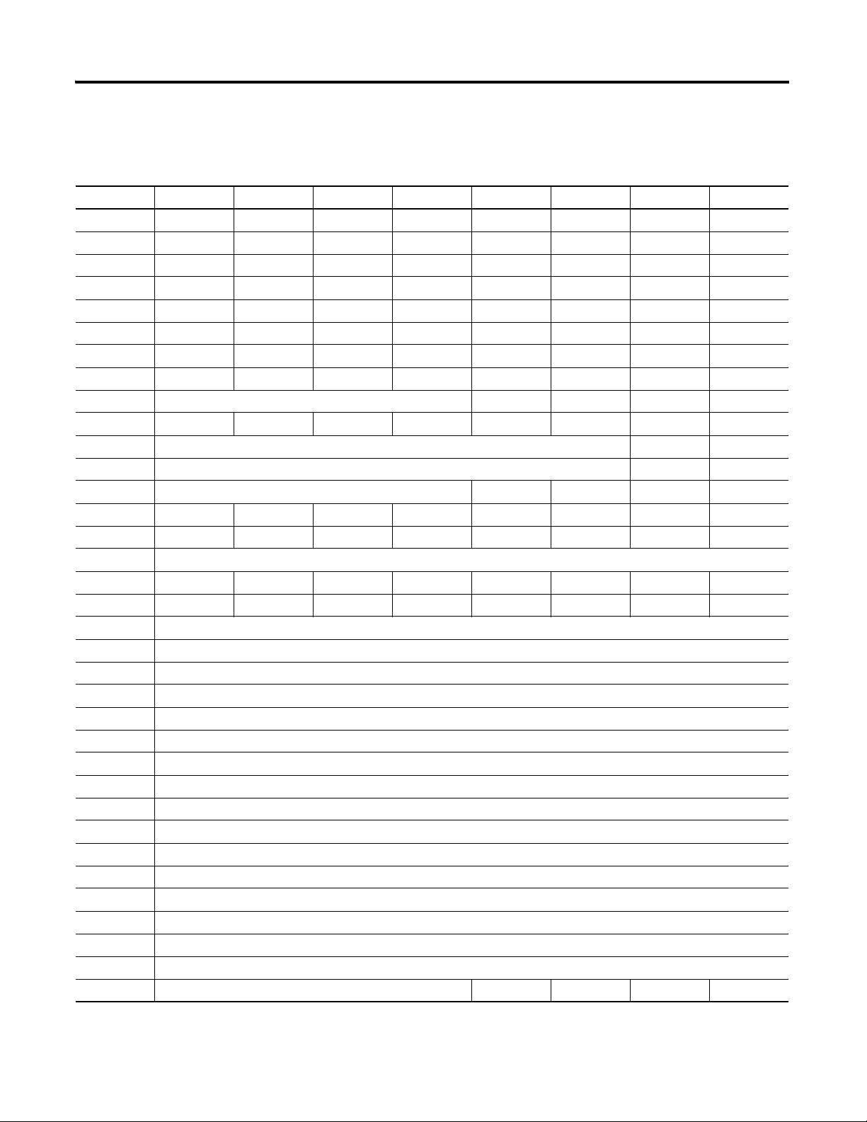
The I/O data that is exchanged with the adapter takes the following form:
Adapter Data Exchange
T → O produced I/O data O → T consumed I/O data
64-bit Status header Run/Idle header
Slot 1 data Slot 1 data
Slot 2 data Slot 2 data
::
::
(1)
Slot N
data
(1)
N is the number of I/O modules
The 64-bit Status header is optional and the packing of the data is dependant
on the selected alignment choice. The exact method for determining the data
structure is covered in the following sections.
Choose a Connection
1 Publication 1734-UM016A-EN-P - October 2010
The Assembly connection supports an optional 64-bit status header and also
supports requests from listen-only originators.
Slot N data
Page 8

2 Introduction
Data Headers
In the Target to Originator (T → O) direction, the adapter can be configured
to produce a status header for the connection. The header consists of an
8-byte bitmap, where bits 1 - 63 indicate the health of each of the 63 possible
backplane connections. This is similar to existing Rack Optimized
connections. A "1" indicates that a module is not connected or that slot is not
populated. A "0" indicates that the module is actively participating in the
connection. Currently, Bit 0 is reserved and should be ignored.
When the header is used, modules may be removed and reinserted without
breaking the I/O connection to the adapter. Modules not present or that are
failed are reflected in the status header.
If the optional status header is not included, the adapter cannot support RIUP
without breaking the I/O connection. If any one I/O module fails or is
removed, the adapter will break the connection to the connection originator.
Since no status is provided, this is the only way to reflect the fact that a
problem exists with the I/O modules on the backplane.
In the Originator to Target (O → T) direction the adapter supports the 4-byte
Run/Idle header. Sending a "1" indicates that the controller is in the Run mode
and that the adapter should apply the data that was just received. Sending a "0"
indicates that the controller is in program or idle mode and that the adapter
should put the I\O modules in their idle mode.
Listen Only Connections
Using an Assembly connection will allow multiple originators to consume data
from the POINT I/O system. However, only one owner of the connection is
permitted. That one owner will control all output devices present in the chassis
as well as the configuration of the connection.
Connection Points
The following table lists the connection points that are supported for the
different connection styles discussed.
Publication 1734-UM016A-EN-P - October 2010
Page 9

Supported Connection Points for Connection Styles
Introduction 3
Connection Configuration
Connection Point
Consumed
Connection Point
Produced
Connection Point
Exclusive Owner 102 100 101
Listen-only 102 191 101
Input-only 102 190 101
Owning with no status header 102 100 103
Listen-only with no status header 102 191 103
Input-only with no status header 102 190 103
Publication 1734-UM016A-EN-P - October 2010
Page 10

4 Introduction
Notes:
Publication 1734-UM016A-EN-P - October 2010
Page 11

Configuration
Chapter
2
About This Chapter
This chapter describes the various configuration options that you can use to
set up assembly connections.
Configure the Connection
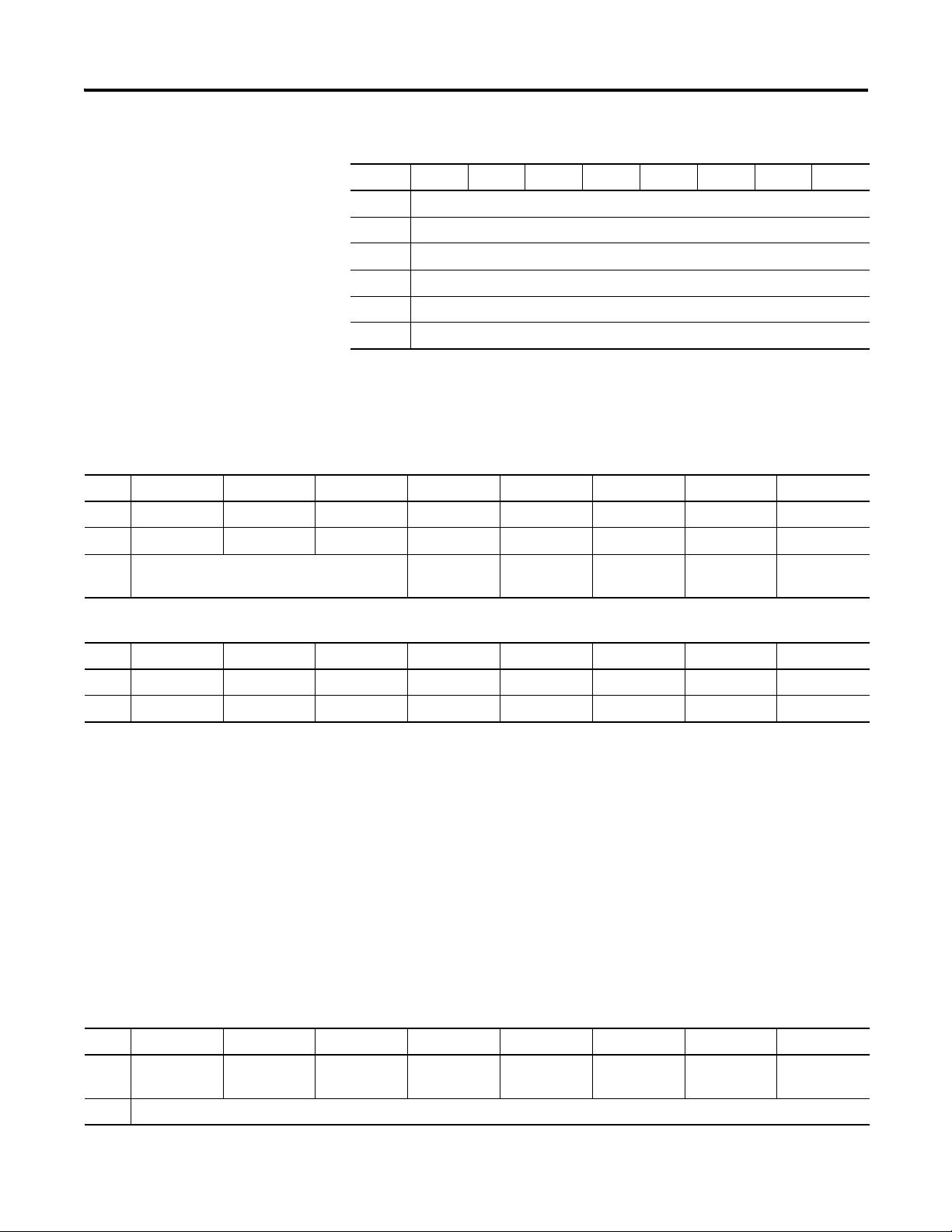
This connection is accepted with or without a configuration assembly present.
If a configuration assembly is present, it must contain the following minimum
information.
Minimal Adapter Configuration Assembly
Byte Bit 7 Bit 6 Bit 5 Bit 4 Bit 3 Bit 2 Bit 1 Bit 0
Config 0 Reserved (Set to 0)
Config 1 Reserved (Set to 0)
Config 2 Reserved (Set to 0)
Config 3 Reserved (Set to 0)
Config 4 Chassis size (Low Byte)
Config 5 Chassis size (High Byte)
Config 6 Alignment for Produced Assembly (T → O)
Config 7 Size per slot (T→ O) (in Bytes)
Config 8 Alignment for Consumed Assembly (O → T)
Config 9 Size per slot (O → T) (in Bytes)
Chassis Size
Before establishing I/O connections, you must configure the 1734 adapters
for chassis size. This ensures that the correct number of modules are present
in the chassis at power up. The chassis size must include 1 count for the
adapter (Chassis Size = number of I/O modules + 1).
5 Publication 1734-UM016A-EN-P - October 2010
Page 12

6 Configuration
TIP
TIP
Data Alignment
Some computing devices require data to be aligned on boundaries that are
proper for their data type. There are several alignment options available to
reduce or prevent shifting operations in the originator:
Byte Boundaries
Each node's I/O data is mapped at the next available byte. Byte data can
appear at any address.
Word Boundaries
If a node's I/O data is one byte in length, it is mapped at the next available
byte. Otherwise the previous data is padded so that the node's data starts on a
16-bit boundary.
This does not mean that every slot occupies two bytes in the image.
Word data can only begin on even addresses, for example, 0, 2, 4, 8,
0xA, or 0xC.
Double Word Boundaries
If a node's I/O data is one byte in length, it is mapped at the next available
byte. If a node's data is two bytes in length, padding is added to ensure that it is
mapped to an even address. If a node's data is greater than 2 bytes in length,
padding is added to ensure that the data is mapped to a Double Word
boundary.
This does not mean that every slot occupies 4 bytes in the image.
Double Word data and array data larger than 2 bytes in size must be
aligned on addresses ending in 0, 4, 8, and 0xC.
Fixed Boundaries
The fixed boundary allows you to choose the fixed "size per slot" that each
module occupies in the I/O data. Mapping size ranges from 1…24 bytes.
The alignment choices are independently selected for each direction; O → T
and T
→ O. If Fixed Boundaries are selected, the Size per Slot choice
determines how many bytes are reserved for each slot in the I/O packet. If the
size selected is larger than a module's data, that module's data is padded with
0's out to the size selected. If the size selected is smaller than a module's data,
that module's data is truncated at the size selected.
Publication 1734-UM016A-EN-P - October 2010
Page 13

Configuration 7
When Fixed Boundaries are selected, the formula for mapping is:
H+(N-1)(size per slot), where N = slot position and H is the size of the
optional status header (8 if used, 0 if not used).
The choice of alignment is highly dependent on the originator used and
application-specific requirements.
• If data size is at a premium, Byte alignment is the most efficient choice.
• If the originator can only process data on DINT boundaries (as is the
case with RSLogix controllers), then Double Word alignment should be
used.
• If ease of programming is desired, the Fixed Boundaries option allows
for easy location of the data within the data packet. Additionally the use
of Fixed Boundaries along with the 1734-ARM module will allow
modules to be added later without having the location of any slot's data
change. The ARM module will reserve data space for future modules.
Since each slot occupies the same size in the data image, when the ARM
module is replaced with a future module, the data boundaries are
preserved.
Individual Module Configuration Options
The request for an Assembly connection is accepted with or without a
configuration assembly present. If a configuration assembly is present, it must
contain the minimum information presented in the Configuring the
Connection section. See TableMinimal Adapter Configuration Assembly on
page 5. If individual module configuration is required, it can be appended to
the end of the minimum configuration structure for any or all modules that
require configuration. The construction of this configuration data structure is
a manual process.
Alternatively any tool that is capable of sending CIP packets can configure the
parameters of individual POINT I/O modules. The configuration is stored
locally in the module's non-volatile storage. When the configuration is sent
from the connection originator via the connection request, the adapter also
stores a copy of this configuration and restores it if that module is ever
replaced. This is similar to the Automatic Device Replacement feature of
DeviceNet scanners. If the configuration is sent from the connection
originator via the connection request, the configuration assembly size is
limited to the maximum packet size of 510 bytes. This may be an issue in larger
systems that require module configuration. Configuring modules through a
separate tool will allow the configuration to be sent to modules individually,
effectively eliminating the packet size limitation. Furthermore, the
configuration tool of choice may provide a rich graphical user interface,
reducing the possibility that configuration is incorrectly entered. One such tool
is RSNetWorx for DeviceNet.
Publication 1734-UM016A-EN-P - October 2010
Page 14

8 Configuration
Module Configuration Sent with the Connection Request
Individual module configuration must be manually constructed and appended
to the minimal configuration assembly specified in the table Minimal Adapter
Configuration Assembly on page 5. For each module that needs to be
configured, the following information must be provided:
Module Configuration Information
Field Data Type Description
Slot number USINT The slot number to identify modules that require
configuration data.
Configuration size USINT The size, in bytes, of the Configuration Data for the
given module. It does not include the size of the first
three fields shown here.
Configuration
assembly instance
Configuration data Array of
UINT The adapter reads this field to access the module
configuration assembly’s instance number.
The configuration assembly data as defined by the
BYTE
module's EDS file.
This structure may be repeated for as many modules as necessary until the
whole assembly exceeds 509 bytes. The module order is not important as long
as all module configuration follows the minimal header information from the
table Minimal Adapter Configuration Assembly on page 5.
If any part of the configuration assembly is wrong (either the minimal
assembly or a portion directed to an I/O module), the connection request will
be rejected with the General Return Code indicating an Error in the Data
Segment (0x09). The Extended Error code will indicate the byte offset into the
configuration data segment where the error was detected. The Configuration
assembly details for all of the 1734 and 1738 I/O modules are presented in
Module Assembly Information on page 31.
Module Configuration with RSNetWorx for DeviceNet
Publication 1734-UM016A-EN-P - October 2010
RSNetWorx for DeviceNet provides a rich parameter-based configuration user
interface. The POINT I/O and ArmorPOINT I/O adapters have the
capability to present their backplane as a DeviceNet subnet to RSLinx. The
subnet can be used to bridge configuration data from RSNetWorx for
DeviceNet to backplane devices. With this method, all configuration for a
POINT I/O backplane can be stored to the DeviceNet network file (.DNT)
and restored via this file if necessary.
Page 15
Configuration 9
Cat # A
E
N
T
I
B
8
I
E
2
C
O
B
4
E
Slot # 0 1 2 3
Module Tx size Rx size
IB8 1 – byte 0
OB4E 1 – byte 1 – byte
IE2C 6
- int
- int
- byte
- byte
0
Calculate the Connection Size
The I/O assembly size is limited to the maximum size that can be specified in
the standard Forward_Open service (509 bytes). The size needs to be manually
calculated based on the alignment choices, inclusion of the optional status
header, and the I/O sizes for the modules present in the chassis. The adapter
validates the connection size in the forward open against what it calculates
from the backplane and the alignment choice. If the two do not match, the
connection request is rejected with extended error code 0x0109, Invalid
Connection Size.
Connection Size Calculation Example
The following system will be used to demonstrate the connection size
calculation. The adapter's produced size (T
optional status header is included. In some software the consumed size
(O
→T) does not need to account for the 4 byte Run/Idle header as it is
assumed and already included. For the example both header sizes have been
included.
POINT I/O system example
→ O) must include 8 bytes if the
T → O alignment T → O size O → T alignment O → T size
1 Byte 16 bytes Byte 5 bytes
status 8 bytes
slot 1 byte
slot 2 int
slot 2 int
slot 2 byte
slot 2 byte
slot 3 byte
Publication 1734-UM016A-EN-P - October 2010
run /idle 4 bytes
slot 3 byte
Page 16
10 Configuration
T → O alignment T → O size O → T alignment O → T size
2 Double Word 19 bytes Double Word 5 bytes
status 8 bytes
slot 1 byte
slot 1 pad
slot 1 pad
slot 1 pad
slot 2 int
slot 2 int
slot 2 byte
slot 2 byte
slot 3 byte
3 6 bytes per slot 26 bytes 1 byte per slot 7 bytes
run / idle 4 bytes
slot 3 byte
status 8 bytes
slot 1 6 bytes
slot 2 6 bytes
slot 3 6 bytes
run /idle 4 bytes
slot 1 byte
slot 2 byte
slot 3 byte
In row 1, the data is packed on byte boundaries. This is the most efficient data
representation when alignment is not a concern.
In row 2 the data for slot 1 is padded so that slot 2's data began on a Double
Word bound ary.
In row 3 every slot takes up the selected size per slot regardless of whether that
module has any data to produce.
This section touches briefly on data alignment. More comprehensive examples
of data alignment are provided in Assembly Structure Examples on page 23.
Troubleshooting Connection Size Errors
If the adapter returns the Invalid Connection Size error in response to a
connection request, it is possible to query the adapter for its calculated size.
Publication 1734-UM016A-EN-P - October 2010
This section highlights a technique that can be used to help resolve connection
size errors.
The adapter cannot validate connection sizes until the request to open the
connection is received. It is within that request that the adapter receives the
alignment choice and status election. Based on all the information in the
request and the modules present, the request may be rejected by the adapter
because of a size error.
Page 17
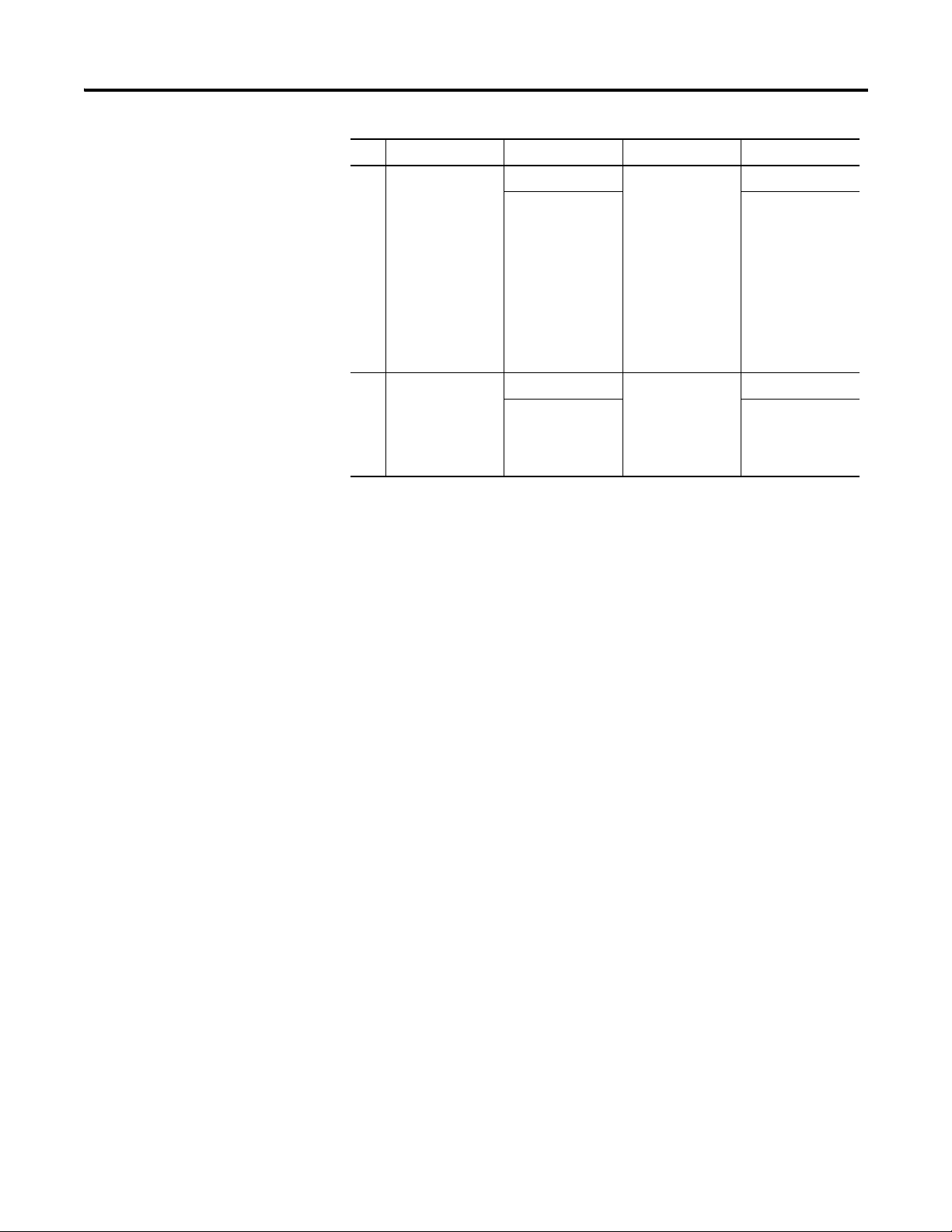
Configuration 11
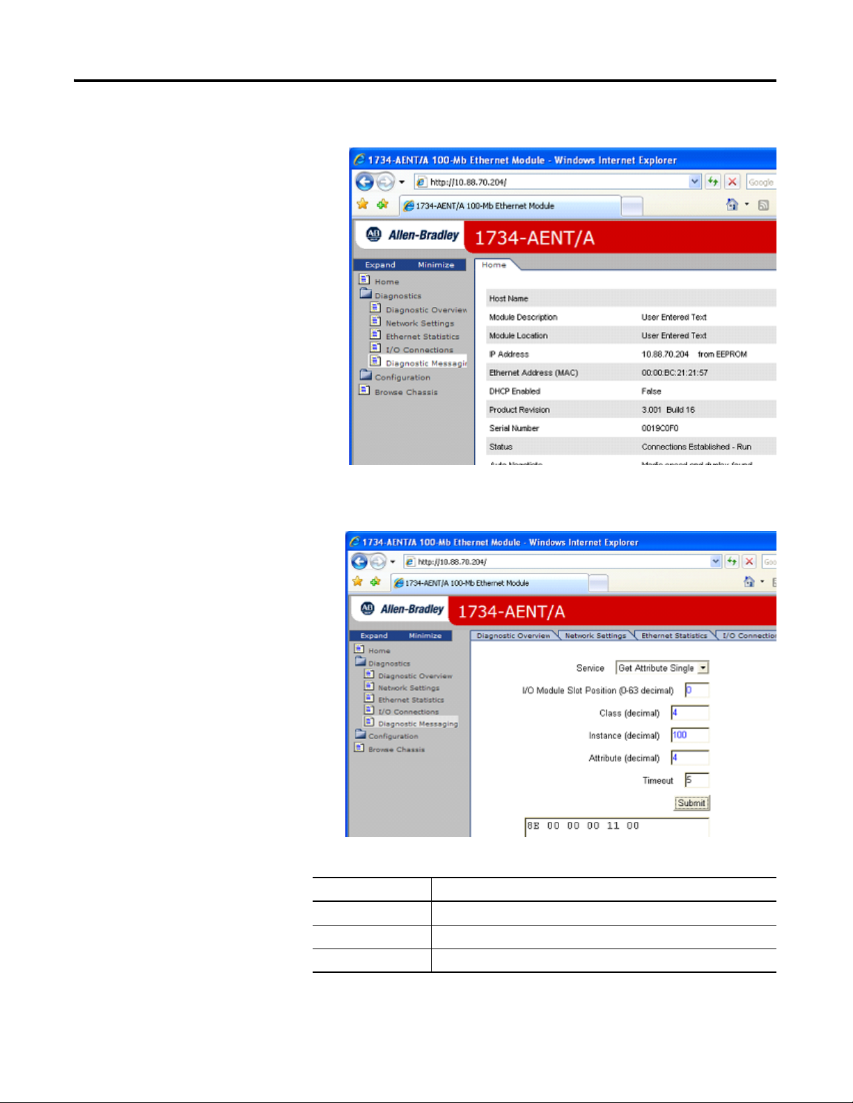
1. Open the adapter's web page and select the Diagnostics folder.
2. On the Diagnostic Messaging tab, enter the Slot, Class, Instance, and
Attribute to get the adapter's calculated connection sizes.
Diagnostic Messaging Field Description
Field Description
Service Get Attribute Single
Slot Position 0
Class 4
Publication 1734-UM016A-EN-P - October 2010
Page 18

12 Configuration
Diagnostic Messaging Field Description
Field Description
Instance 100 (O → T data)
101 (T → O data with status)
103 (T → O data without status)
Attribute 4
Response 8E 00 00 00 xx xx
8E 00 — Indicates message was processed successfully
00 00 — 0 = success. Non-zero indicates an error code
xx xx — Indicates size (Little Endian format)
(1)
in Little Endian format, the least significant byte is shown first. A returned value of A2 01 should be interpreted
as 0x01A2 hex (418 decimal).
(1)
Once you have the sizes from the adapter, return to your calculations to
resolve the differences between your expected size and the size from the
adapter.
Publication 1734-UM016A-EN-P - October 2010
Page 19
Using an Assembly Connection
Chapter
3
Use an Assembly Connection with RSNetWorx for EtherNet/IP
This section provides an illustration of the steps needed to configure the
Assembly connection using RSNetWorx for EtherNet/IP.
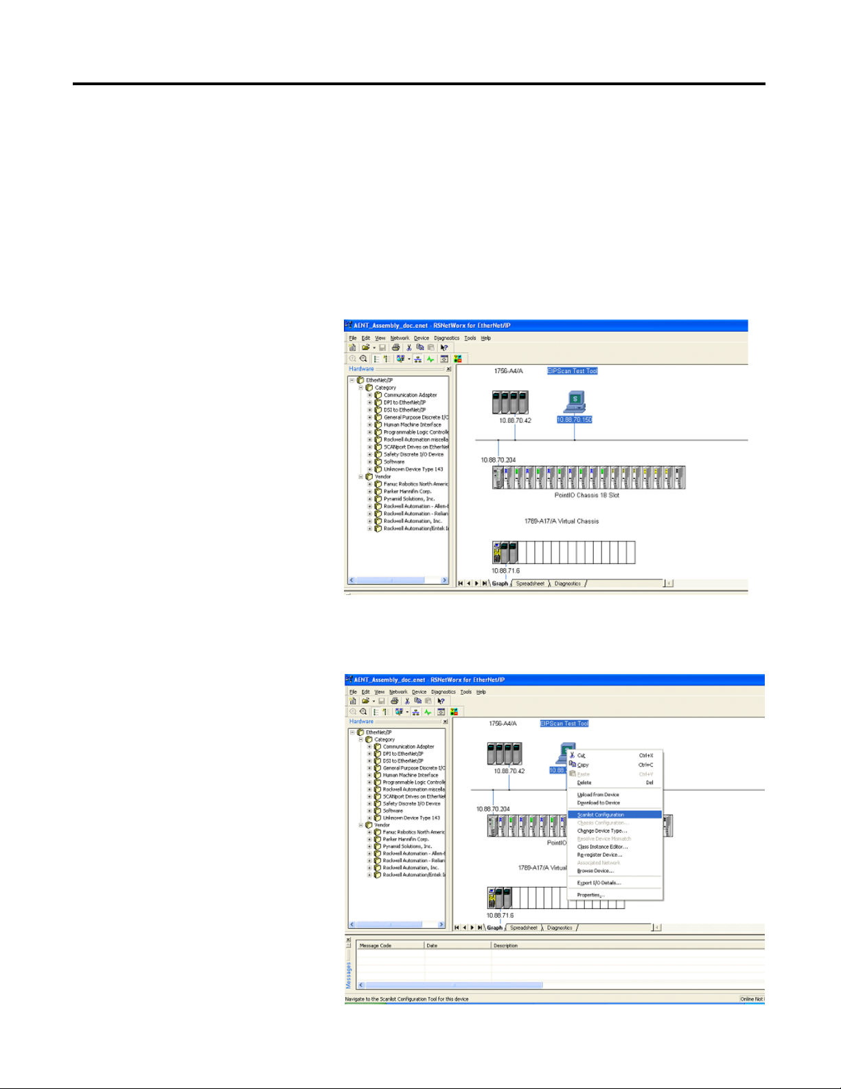
1. Browse the EtherNet/IP network.
2. Select the connection originator that will make the connection to the
1734-AENT. Right click that device and select Scanlist Configuration to
launch the Scanlist Configuration tool.
13 Publication 1734-UM016A-EN-P - October 2010
Page 20
14 Using an Assembly Connection
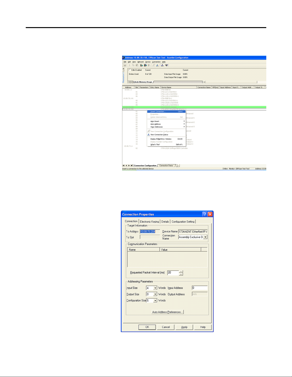
3. Right click the targeted adapter and select Insert Connection to display
the Connection Properties dialog.
4. On the Connection tab of this dialog, select the connection from the
Connection Name pull-down (for example, Exclusive Owner and
Listen-Only connections). Listen-Only connections are only accepted if
an Exclusive Owner connection already exists.
Publication 1734-UM016A-EN-P - October 2010
Page 21
Using an Assembly Connection 15
TIP
You can also select the Requested Packet Interval and connection sizes.
For a full discussion on connections sizes, refer to the Configuration
Setting tab step that follows and Calculate the Connection Size. The
defaults reflect an empty system (with the adapter only).
In RSNetWorx, the 4-byte Run/Idle header is not considered when
calculating the Output Size. When you enter the connection size on
this dialog, make sure to subtract 4 bytes from your calculated size.
Also note that this dialog expresses the size in Words. If your
calculation was performed in Bytes, you must divide by 2.
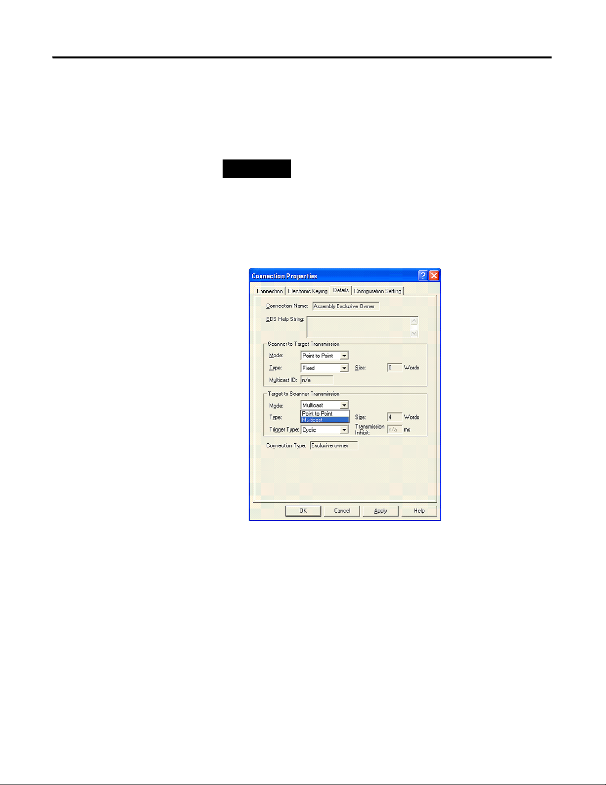
5. In the Details tab, you can select between Point to Point and Multicast
for the Target to Scanner data.
Publication 1734-UM016A-EN-P - October 2010
Page 22
16 Using an Assembly Connection
TIP
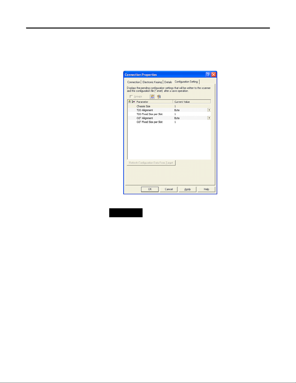
6. The Configuration Setting tab displays the configuration options for the
connection. Here, you can specify the Chassis Size and Data Alignment.
The terms T2O and O2T are abbreviations for Target to Originator and
Originator to Target.
Use an Assembly Connection with RSLogix5000
Remember when specifying the Chassis Size to include 1 for the
adapter.
See Data Alignment for alignment choices.
The Assembly connection can be used with RSLogix5000 and the Generic
EtherNet/IP profile. When this connection is used in RSLogix5000, there are
no intelligent Tags created for the adapter. All Input, Output, and
Configuration data are in unstructured Tag arrays.
Publication 1734-UM016A-EN-P - October 2010
Page 23
Using an Assembly Connection 17
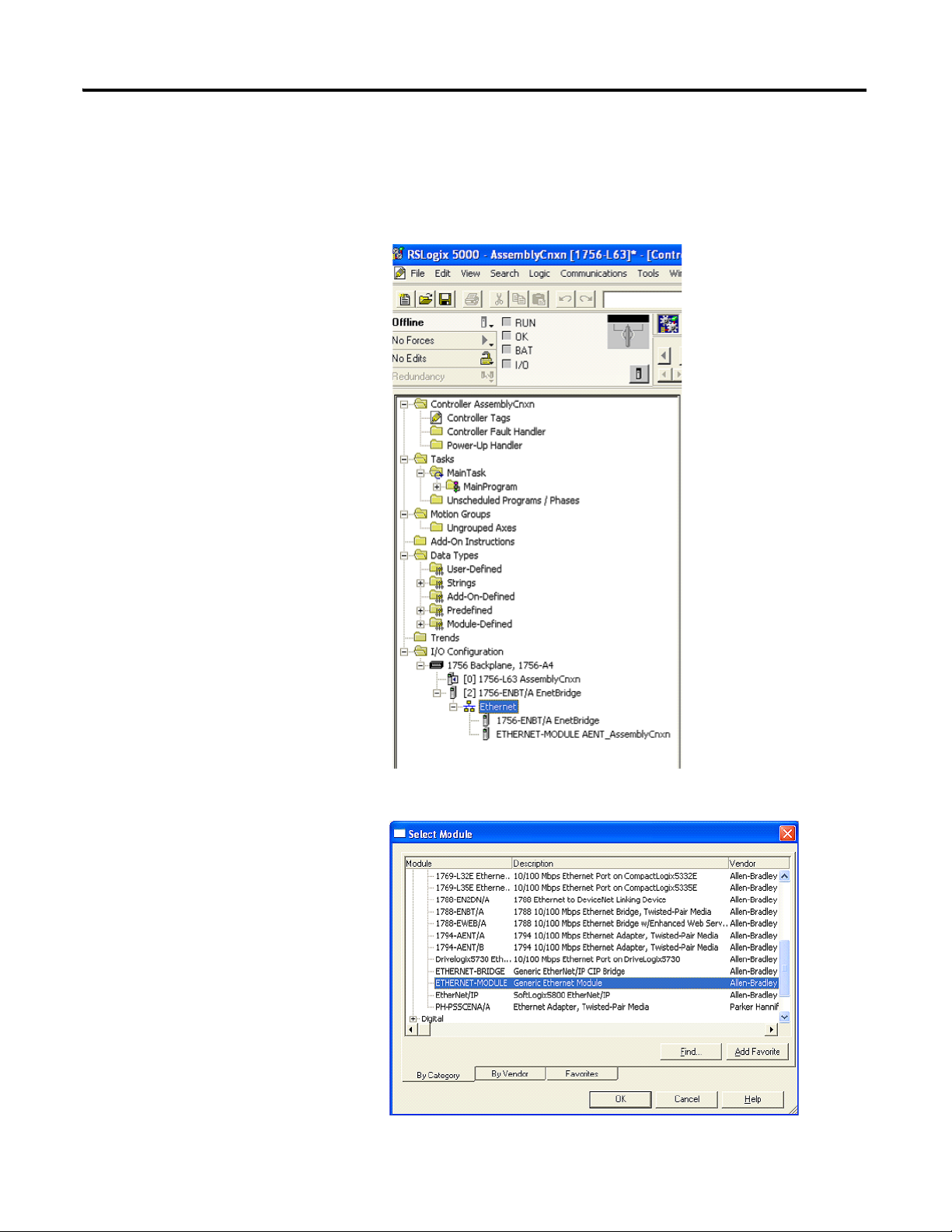
Add the Hardware to the I/O Configuration Tree
1. Add a new module to the Ethernet network in the I/O Configuration
section of the Controller Organizer pane.
2. Select a Generic Ethernet Module.
Publication 1734-UM016A-EN-P - October 2010
Page 24
18 Using an Assembly Connection
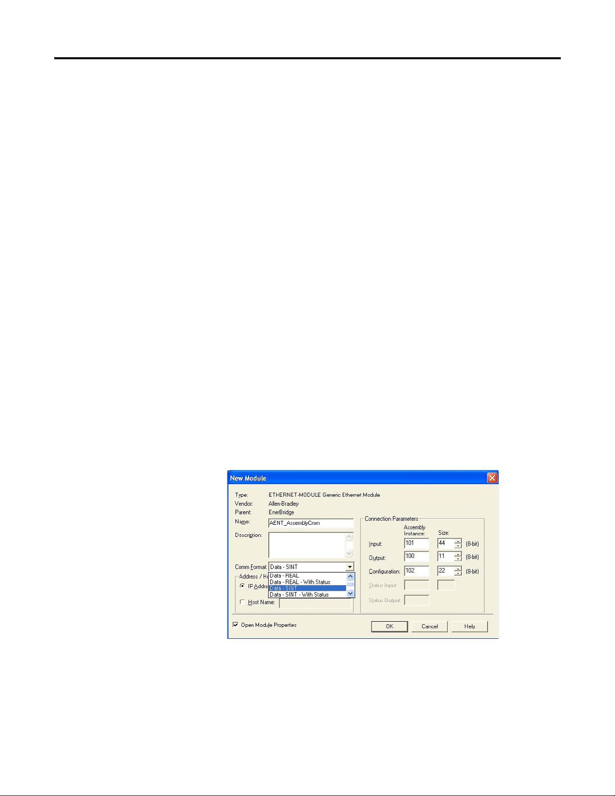
Enter the Connection Parameters
In the New Module Properties dialog, enter Connection Parameters, the
Comm Format, the module's IP Address, and a name.
Enter a Name for the module that RSLogix 5000 uses in the tags that are
created for this module. The Data - SINT Comm Format should be selected,
indicating that all sizes are to be interpreted as a number of bytes. If this
connection is a Listen only connection, select the Input Data - SINT Comm
Format since it is otherwise not possible to enter an Output config assembly
size of 0.
Next, enter the Assembly Instances for the desired connection as
described in Connection Points. Enter the sizes (in bytes) for the Input and
Output instances per your calculations. See Calculate the Connection Size for
details on obtaining the sizes. If the optional status header is being used, its
size (8 bytes) must be included in the Input Size. For RSLogix 5000 the Output
Size does not include the Run/Idle header. Here the terms Input and Output
refer to the adapter's Produced and Consumed data respectively.
It is possible to make the connection without sending any
configuration data. The adapter's Chassis Size can be set from its web
page and the adapter will align produced and consumed data by
default on byte boundaries. If these options and the default configuration of all
I/O modules are acceptable, a 0 can be entered for the Configuration Size on
the Module Properties dialog. The configuration Assembly Instance must be
entered even if the size is 0. The following section will describe the steps taken
when configuration is needed.
Publication 1734-UM016A-EN-P - October 2010
Build the Configuration Tag
If any configuration is required, the minimum configuration header must be
sent and then any individual module configuration may follow. Open the
Page 25
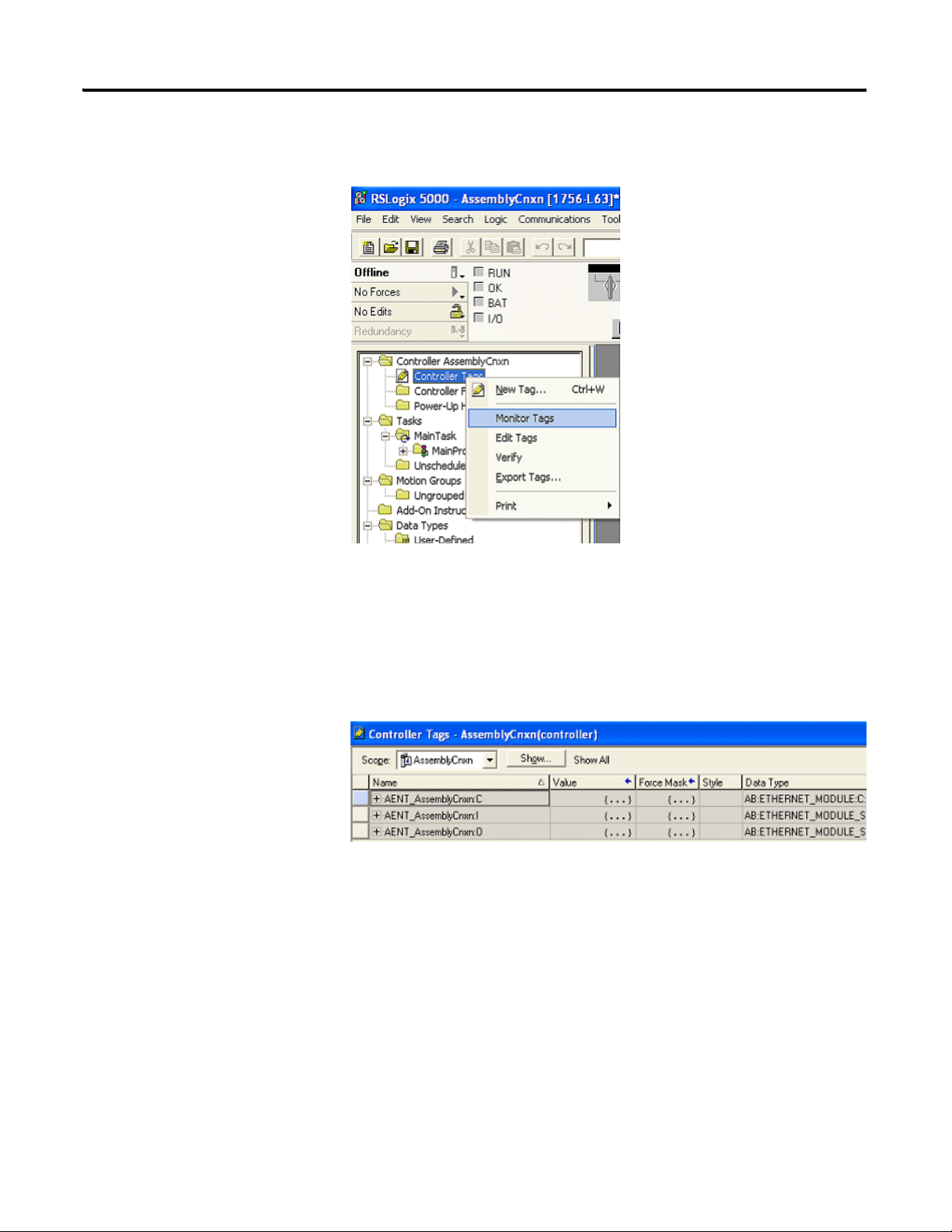
Using an Assembly Connection 19
Controller Tags by right-clicking the Controller Tags option from the
Controller Organizer pane. Select Monitor Tags.
Monitor Tags
You should see three Tags with the module's name. They will have an C, I, or
O suffix denoting Configuration, Input, or Output respectively. Note that the I
and O Tags are sized according to the sizes that were entered on the properties
page. The C Tag always has 400 bytes allocated for it regardless of the size
specified.
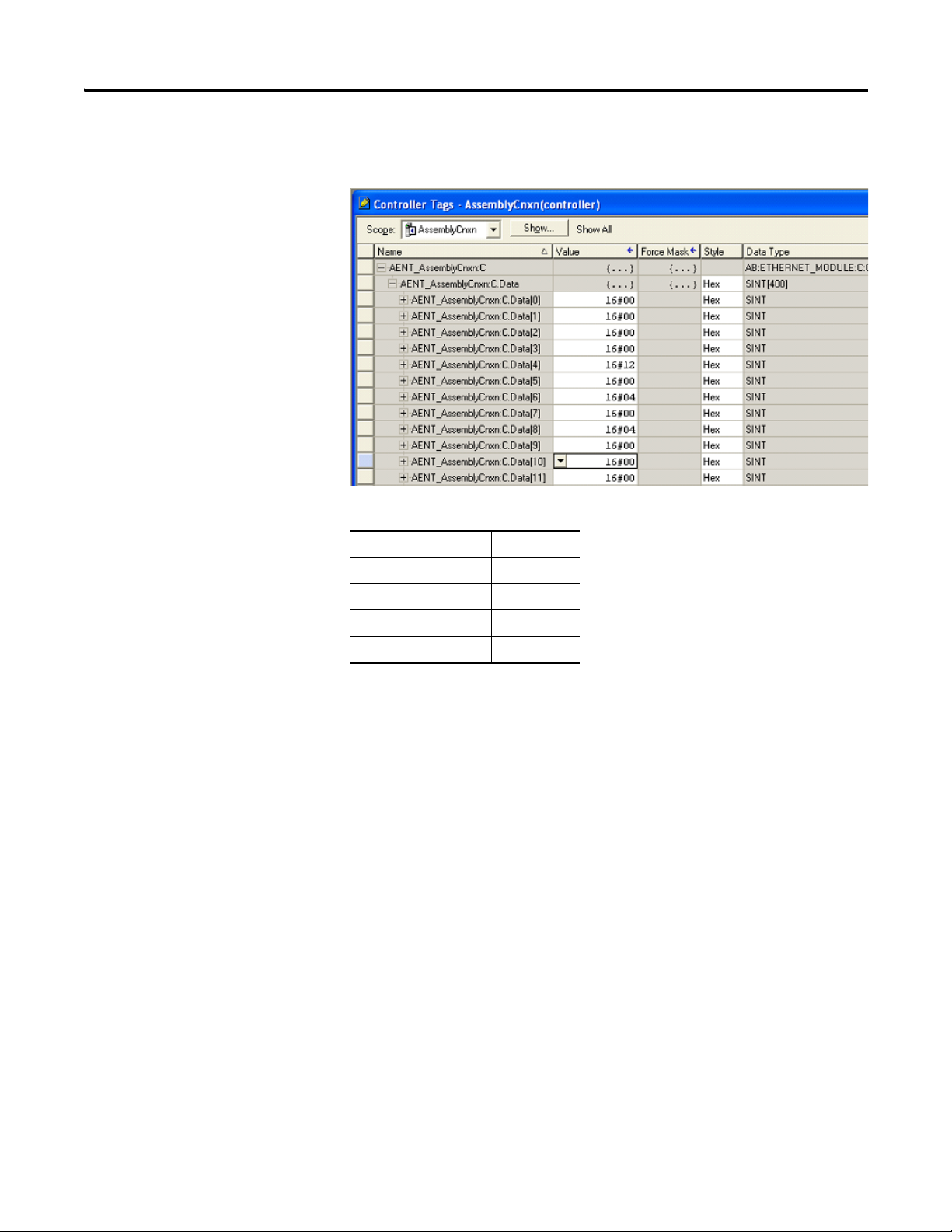
Add Configuration Header
Bytes 0…9 must contain the minimum configuration header information
described in Minimal Adapter Configuration Assembly. As can be seen from
the figure below, the Chassis Size is set to 0x12 (18 decimal). The produced
Publication 1734-UM016A-EN-P - October 2010
Page 26
20 Using an Assembly Connection
and consumed alignment choice is Double Word alignment which is
enumerated as a 4. See the following table for valid alignment values.
Alignment choices for configuration header
Alignment Choice Value
Byte 0
Word 2
Double Word 4
Fixed size per slot 0xFF
Add I/O Module Configuration
If individual module configuration is required, it can be appended to
the configuration header. In the example shown below a 1734-OB4E module
is being configured. Byte 10 indicates that the data is to be sent to slot 2. Byte
11 specifies the size of the data as 8 bytes. Bytes 12 and 13 specify the OB4E
module configuration assembly instance 0x7B. The instance number is entered
in little endian (least significant byte first). In byte 16 the value of 7 indicates
that when the module is in Idle mode, Hold Last State should be enabled for
channels 0, 1, and 2 but not channel 3. If more module configuration is
needed, it could begin at byte 22 with the slot number of the next module to
be configured.
Publication 1734-UM016A-EN-P - October 2010
Page 27

Using an Assembly Connection 21
For more information on configuration, see 1734/1738 I/O Module
Assembly Information.
After the configuration has been entered into the tag, remember to
save the RSLogix 5000 project. The tags are only retained upon a save. Also
remember that any configuration added here must be reflected in the
Configuration Size of the Connection Parameters entered on the Module
Properties dialog.
If any part of the configuration assembly is wrong (either the minimal
assembly or a portion directed to an I/O module), the connection request will
be rejected with the General Return Code indicating an Error in the Data
Segment (0x09). The Extended Error code will indicate the byte offset into the
configuration data segment where the error was detected.
Publication 1734-UM016A-EN-P - October 2010
Page 28

22 Using an Assembly Connection
The error shown above was created by entering an invalid configuration
assembly size on the Module Properties page. A size of 18 bytes was entered.
The error here points to an offset of 0x000b (11 decimal). If we return to the
configuration tag, byte 0x000b is the location that contains the size of the I/O
module configuration. The header is 10 bytes and the module has 8 bytes of
configuration. However, we have neglected to add the 4 bytes of overhead
needed to describe the slot 2 configuration. When the adapter parsed the
configuration assembly to byte 0x000b it saw that it needed 8 more bytes of
information. It had already parsed through byte 11, therefore 18 would not be
an adequate size. The adapter returns the offset of the first byte where the
error is detected (0x000b).
Publication 1734-UM016A-EN-P - October 2010
Page 29

Assembly Structure
Chapter
4
Assembly Structure Examples
Produced Assembly, Byte Aligned
Byte, Word, and Double Word Alignment
The following chassis is used to demonstrate how the data is aligned for the
Byte, Word, and Double Word alignment options. This chassis was
intentionally assembled as shown to demonstrate as many use cases as
possible. Discrete and analog modules are intermixed. An ARM module is
used to reserve space for a future device. The 1734-IB4D module in slot 8 is
configured to produce 2 bytes while the IB4D module in slot 7 is configured
to produce 1 byte. The ASCII module in slot 10 is configured to produce
9 bytes.
Example POINT system
A
A
O
W
4
I
B
4
3
I
I
Cat # A
B
E
4
N
T
Slot # 0 1234567891011121
I
B
B
8
2
O
O
S
R
E
B
B
B
B
B
C
M
2
4
4
8
4
2
C
D
D
E
E
E
I
I
I
O
Byte Bit 7 Bit 6 Bit5 Bit 4 Bit 3 Bit 2 Bit 1 Bit 0
Produce 0 Slot 7 status Slot 6 status Slot 5 status Slot 4 status Slot 3 status Slot 2 status Slot1 status Slot 0 status
Produce 1 Slot 15 status Slot 14 status Slot 13 status Slot 12 status Slot 11 status Slot 10 status Slot 9 status Slot 8 status
Produce 2 Slot 23 status Slot 22 status Slot 21 status Slot 20 status Slot 19 status Slot 18 status Slot 17 status Slot 16 status
Produce 3 Slot 31 status Slot 30 status Slot 29 status Slot 28 status Slot 27 status Slot 26 status Slot 25 status Slot 24 status
Produce 4 Slot 39 status Slot 38 status Slot 37 status Slot 36 status Slot 35 status Slot 34 status Slot 33 status Slot 32 status
Produce 5 Slot 47 status Slot 46 status Slot 45 status Slot 44 status Slot 43 status Slot 42 status Slot 41 status Slot 40 status
Produce 6 Slot 55 status Slot 54 status Slot 53 status Slot 52 status Slot 51 status Slot 50 status Slot 49 status Slot 48 status
Produce 7 Slot 63 status Slot 62 status Slot 61 status Slot 60 status Slot 59 status Slot 58 status Slot 57 status Slot 56 status
Produce 8 Reserved Slot 1 Bit 3 Slot 1 Bit 2 Slot 1 Bit 1 Slot 1 Bit 0
Produce 9 Slot 2 Bit 7 Slot 2 Bit 6 Slot 2 Bit 5 Slot 2 Bit 4 Slot 2 Bit 3 Slot 2 Bit 2 Slot 2 Bit 1 Slot 2 Bit 0
Produce 10 Reserved Slot 3 Bit 1 Slot 3 Bit 0
Produce 11 Reserved Slot 4 Bit 1 Slot 4 Bit 0
Produce 12 Reserved Slot 5 Bit 3 Slot 5 Bit 2 Slot 5 Bit 1 Slot 5 Bit 0
Produce 13 Slot 6 Bit 7 Slot 6 Bit 6 Slot 6 Bit 6 Slot 6 Bit 4 Slot 6 Bit 3 Slot 6 Bit 2 Slot 6 Bit 1 Slot 6 Bit 0
Produce 14 Slot 7 Bit 7 Slot 7 Bit 6 Slot 7 Bit 5 Slot 7 Bit 4 Slot 7 Bit 3 Slot 7 Bit 2 Slot 7 Bit 1 Slot 7 Bit 0
23 Publication 1734-UM016A-EN-P - October 2010
Page 30

24 Assembly Structure
Produced Assembly, Byte Aligned
Byte Bit 7 Bit 6 Bit5 Bit 4 Bit 3 Bit 2 Bit 1 Bit 0
Produce 15 Slot 8 Bit 7 Slot 8 Bit 6 Slot 8 Bit 5 Slot 8 Bit 4 Slot 8 Bit 3 Slot 8 Bit 2 Slot 8 Bit 1 Slot 8 Bit 0
Produce 16 Slot 8 Bit 15 Slot 8 Bit 14 Slot 8 Bit 13 Slot 8 Bit 12 Slot 8 Bit 11 Slot 8 Bit 10 Slot 8 Bit 9 Slot 8 Bit 8
Produce 17 Slot 9 Channel 0 - Low Byte
Produce 18 Slot 9 Channel 0 - High Byte
Produce 19 Slot 9 Channel 1 - Low Byte
Produce 20 Slot 9 Channel 1 - High Byte
Produce 21 Slot 9 Channel 0 - Status
Produce 22 Slot 9 Channel 1 - Status
Produce 23 Slot 10 ASCII Data 1
Produce 24 Slot 10 ASCII Data 2
Produce 25 Slot 10 ASCII Data 3
Produce 26 Slot 10 ASCII Data 4
Produce 27 Slot 10 ASCII Data 5
Produce 28 Slot 10 ASCII Data 6
Produce 29 Slot 10 ASCII Data 7
Produce 30 Slot 10 ASCII Data 8
Produce 31 Slot 10 ASCII Data End of String Delimiter
Produce 32 Slot 11 ARM - Reserved Byte
Produce 33 Reserved Slot 13 Bit 3 Slot 13 Bit 2 Slot 13 Bit 1 Slot 13 Bit 0
Consumed Assembly, Byte Aligned
Byte Bit 7 Bit 6 Bit5 Bit 4 Bit 3 Bit 2 Bit 1 Bit 0
Consume 0 Reserved Run/Idle
Consume 1 Reserved
Consume 2 Reserved
Consume 3 Reserved
Consume 4 Reserved Slot 4 Bit 1 Slot 4 Bit 0
Consume 5 Reserved Slot 5 Bit 3 Slot 5 Bit 2 Slot 5 Bit 1 Slot 5 Bit 0
Consume 6 Slot 6 Bit 7 Slot 6 Bit 6 Slot 6 Bit 5 Slot 6 Bit 4 Slot 6 Bit 3 Slot 6 Bit 2 Slot 6 Bit 1 Slot 6 Bit 0
Consume 7 Slot 10 ASCII Data 1
Consume 8 Slot 10 ASCII Data 2
Consume 9 Slot 10 ASCII Data 3
Consume 10 Slot 10 ASCII Data 4
Consume 11 Slot 10 ASCII Data 5
Consume 12 Slot 10 ASCII Data End of String Delimiter
Consume 13 Reserved Slot 12 Bit 3 Slot 12 Bit 2 Slot 12 Bit 1 Slot 12 Bit 0
Publication 1734-UM016A-EN-P - October 2010
Page 31
Assembly Structure 25
Produced Assembly, Word Aligned
Byte Bit 7 Bit 6 Bit5 Bit 4 Bit 3 Bit 2 Bit 1 Bit 0
Produce 0 Slot 7 status Slot 6 status Slot 5 status Slot 4 status Slot 3 status Slot 2 status Slot1 status Slot 0 status
Produce 1 Slot 15 status Slot 14 status Slot 13 status Slot 12 status Slot 11 status Slot 10 status Slot 9 status Slot 8 status
Produce 2 Slot 23 status Slot 22 status Slot 21 status Slot 20 status Slot 19 status Slot 18 status Slot 17 status Slot 16 status
Produce 3 Slot 31 status Slot 30 status Slot 29 status Slot 28 status Slot 27 status Slot 26 status Slot 25 status Slot 24 status
Produce 4 Slot 39 status Slot 38 status Slot 37 status Slot 36 status Slot 35 status Slot 34 status Slot 33 status Slot 32 status
Produce 5 Slot 47 status Slot 46 status Slot 45 status Slot 44 status Slot 43 status Slot 42 status Slot 41 status Slot 40 status
Produce 6 Slot 55 status Slot 54 status Slot 53 status Slot 52 status Slot 51 status Slot 50 status Slot 49 status Slot 48 status
Produce 7 Slot 63 status Slot 62 status Slot 61 status Slot 60 status Slot 59 status Slot 58 status Slot 57 status Slot 56 status
Produce 8 Reserved Slot 1 Bit 3 Slot 1 Bit 2 Slot 1 Bit 1 Slot 1 Bit 0
Produce 9 Slot 2 Bit 7 Slot 2 Bit 6 Slot 2 Bit 5 Slot 2 Bit 4 Slot 2 Bit 3 Slot 2 Bit 2 Slot 2 Bit 1 Slot 2 Bit 0
Produce 10 Reserved Slot 3 Bit 1 Slot 3 Bit 0
Produce 11 Reserved Slot 4 Bit 1 Slot 4 Bit 0
Produce 12 Reserved Slot 5 Bit 3 Slot 5 Bit 2 Slot 5 Bit 1 Slot 5 Bit 0
Produce 13 Slot 6 Bit 7 Slot 6 Bit 6 Slot 6 Bit 6 Slot 6 Bit 4 Slot 6 Bit 3 Slot 6 Bit 2 Slot 6 Bit 1 Slot 6 Bit 0
Produce 14 Slot 7 Bit 7 Slot 7 Bit 6 Slot 7 Bit 5 Slot 7 Bit 4 Slot 7 Bit 3 Slot 7 Bit 2 Slot 7 Bit 1 Slot 7 Bit 0
Produce 15 Pad
Produce 16 Slot 8 Bit 7 Slot 8 Bit 6 Slot 8 Bit 5 Slot 8 Bit 4 Slot 8 Bit 3 Slot 8 Bit 2 Slot 8 Bit 1 Slot 8 Bit 0
Produce 17 Slot 8 Bit 15 Slot 8 Bit 14 Slot 8 Bit 13 Slot 8 Bit 12 Slot 8 Bit 11 Slot 8 Bit 10 Slot 8 Bit 9 Slot 8 Bit 8
Produce 18 Slot 9 Channel 0 - Low Byte
Produce 19 Slot 9 Channel 0 - High Byte
Produce 20 Slot 9 Channel 1 - Low Byte
Produce 21 Slot 9 Channel 1 - High Byte
Produce 22 Slot 9 Channel 0 - Status
Produce 23 Slot 9 Channel 1 - Status
Produce 24 Slot 10 ASCII Data 1
Produce 25 Slot 10 ASCII Data 2
Produce 26 Slot 10 ASCII Data 3
Produce 27 Slot 10 ASCII Data 4
Produce 28 Slot 10 ASCII Data 5
Produce 29 Slot 10 ASCII Data 6
Produce 30 Slot 10 ASCII Data 7
Produce 31 Slot 10 ASCII Data 8
Produce 32 Slot 10 ASCII Data End of String Delimiter
Produce 33 Slot 11 ARM - Reserved Byte
Produce 34 Reserved Slot 13 Bit 3 Slot 13 Bit 2 Slot 13 Bit 1 Slot 13 Bit 0
Publication 1734-UM016A-EN-P - October 2010
Page 32

26 Assembly Structure
Consumed Assembly, Word Aligned
Byte Bit 7 Bit 6 Bit5 Bit 4 Bit 3 Bit 2 Bit 1 Bit 0
Consume 0 Reserved Run/Idle
Consume 1 Reserved
Consume 2 Reserved
Consume 3 Reserved
Consume 4 Reserved Slot 4 Bit 1 Slot 4 Bit 0
Consume 5 Reserved Slot 5 Bit 3 Slot 5 Bit 2 Slot 5 Bit 1 Slot 5 Bit 0
Consume 6 Slot 6 Bit 7 Slot 6 Bit 6 Slot 6 Bit 5 Slot 6 Bit 4 Slot 6 Bit 3 Slot 6 Bit 2 Slot 6 Bit 1 Slot 6 Bit 0
Consume 7 Pad
Consume 8 Slot 10 ASCII Data 1
Consume 9 Slot 10 ASCII Data 2
Consume 10 Slot 10 ASCII Data 3
Consume 11 Slot 10 ASCII Data 4
Consume 12 Slot 10 ASCII Data 5
Consume 13 Slot 10 ASCII Data End of String Delimiter
Consume 14 Reserved Slot 12 Bit 3 Slot 12 Bit 2 Slot 12 Bit 1 Slot 12 Bit 0
Produced Assembly, Double Word Aligned
Byte Bit 7 Bit 6 Bit5 Bit 4 Bit 3 Bit 2 Bit 1 Bit 0
Produce 0 Slot 7 status Slot 6 status Slot 5 status Slot 4 status Slot 3 status Slot 2 status Slot1 status Slot 0 status
Produce 1 Slot 15 status Slot 14 status Slot 13 status Slot 12 status Slot 11 status Slot 10 status Slot 9 status Slot 8 status
Produce 2 Slot 23 status Slot 22 status Slot 21 status Slot 20 status Slot 19 status Slot 18 status Slot 17 status Slot 16 status
Produce 3 Slot 31 status Slot 30 status Slot 29 status Slot 28 status Slot 27 status Slot 26 status Slot 25 status Slot 24 status
Produce 4 Slot 39 status Slot 38 status Slot 37 status Slot 36 status Slot 35 status Slot 34 status Slot 33 status Slot 32 status
Produce 5 Slot 47 status Slot 46 status Slot 45 status Slot 44 status Slot 43 status Slot 42 status Slot 41 status Slot 40 status
Produce 6 Slot 55 status Slot 54 status Slot 53 status Slot 52 status Slot 51 status Slot 50 status Slot 49 status Slot 48 status
Produce 7 Slot 63 status Slot 62 status Slot 61 status Slot 60 status Slot 59 status Slot 58 status Slot 57 status Slot 56 status
Produce 8 Reserved Slot 1 Bit 3 Slot 1 Bit 2 Slot 1 Bit 1 Slot 1 Bit 0
Produce 9 Slot 2 Bit 7 Slot 2 Bit 6 Slot 2 Bit 5 Slot 2 Bit 4 Slot 2 Bit 3 Slot 2 Bit 2 Slot 2 Bit 1 Slot 2 Bit 0
Produce 10 Reserved Slot 3 Bit 1 Slot 3 Bit 0
Produce 11 Reserved Slot 4 Bit 1 Slot 4 Bit 0
Produce 12 Reserved Slot 5 Bit 3 Slot 5 Bit 2 Slot 5 Bit 1 Slot 5 Bit 0
Produce 13 Slot 6 Bit 7 Slot 6 Bit 6 Slot 6 Bit 6 Slot 6 Bit 4 Slot 6 Bit 3 Slot 6 Bit 2 Slot 6 Bit 1 Slot 6 Bit 0
Produce 14 Slot 7 Bit 7 Slot 7 Bit 6 Slot 7 Bit 5 Slot 7 Bit 4 Slot 7 Bit 3 Slot 7 Bit 2 Slot 7 Bit 1 Slot 7 Bit 0
Produce 15 Pad
Produce 16 Slot 8 Bit 7 Slot 8 Bit 6 Slot 8 Bit 5 Slot 8 Bit 4 Slot 8 Bit 3 Slot 8 Bit 2 Slot 8 Bit 1 Slot 8 Bit 0
Publication 1734-UM016A-EN-P - October 2010
Page 33

Assembly Structure 27
Produced Assembly, Double Word Aligned
Byte Bit 7 Bit 6 Bit5 Bit 4 Bit 3 Bit 2 Bit 1 Bit 0
Produce 17 Slot 8 Bit 15 Slot 8 Bit 14 Slot 8 Bit 13 Slot 8 Bit 12 Slot 8 Bit 11 Slot 8 Bit 10 Slot 8 Bit 9 Slot 8 Bit 8
Produce 18 Pad
Produce 19 Pad
Produce 20 Slot 9 Channel 0 - Low Byte
Produce 21 Slot 9 Channel 0 - High Byte
Produce 22 Slot 9 Channel 1 - Low Byte
Produce 23 Slot 9 Channel 1 - High Byte
Produce 24 Slot 9 Channel 0 - Status
Produce 25 Slot 9 Channel 1 - Status
Produce 26 Pad
Produce 27 Pad
Produce 28 Slot 10 ASCII Data 1
Produce 29 Slot 10 ASCII Data 2
Produce 30 Slot 10 ASCII Data 3
Produce 31 Slot 10 ASCII Data 4
Produce 32 Slot 10 ASCII Data 5
Produce 33 Slot 10 ASCII Data 6
Produce 34 Slot 10 ASCII Data 7
Produce 35 Slot 10 ASCII Data 8
Produce 36 Slot 10 ASCII Data End of String Delimiter
Produce 37 Slot 11 ARM - Reserved Byte
Produce 38 Reserved Slot 13 Bit 3 Slot 13 Bit 2 Slot 13 Bit 1 Slot 13 Bit 0
Consumed Assembly, Double Word Aligned
Byte Bit 7 Bit 6 Bit5 Bit 4 Bit 3 Bit 2 Bit 1 Bit 0
Consume 0 Reserved Run/Idle
Consume 1 Reserved
Consume 2 Reserved
Consume 3 Reserved
Consume 4 Reserved Slot 4 Bit 1 Slot 4 Bit 0
Consume 5 Reserved Slot 5 Bit 3 Slot 5 Bit 2 Slot 5 Bit 1 Slot 5 Bit 0
Consume 6 Slot 6 Bit 7 Slot 6 Bit 6 Slot 6 Bit 5 Slot 6 Bit 4 Slot 6 Bit 3 Slot 6 Bit 2 Slot 6 Bit 1 Slot 6 Bit 0
Consume 7 Pad
Consume 8 Slot 10 ASCII Data 1
Consume 9 Slot 10 ASCII Data 2
Consume 10 Slot 10 ASCII Data 3
Publication 1734-UM016A-EN-P - October 2010
Page 34

28 Assembly Structure
Consumed Assembly, Double Word Aligned
Byte Bit 7 Bit 6 Bit5 Bit 4 Bit 3 Bit 2 Bit 1 Bit 0
Consume 11 Slot 10 ASCII Data 4
Consume 12 Slot 10 ASCII Data 5
Consume 13 Slot 10 ASCII Data End of String Delimiter
Consume 14 Reserved Slot 12 Bit 3 Slot 12 Bit 2 Slot 12 Bit 1 Slot 12 Bit 0
Fixed Size per Slot Alignment
The following chassis is used to demonstrate how the Fixed Size per Slot
alignment option might be used. This chassis is built to show a machine that
sometimes uses 5 analog modules, but usually only needs 3 modules. In order
to maintain data structure consistency (and therefore the same control logic),
Fixed Size per Slot alignment of 6 bytes is used and the unused slots are
populated with Address Reserve Modules.
Example POINT system with unused slots
A
A
I
I
I
I
Cat # A
Slot # 012345678
Produced Assembly, Fixed Size per Slot Alignment
Byte Bit 7 Bit 6 Bit5 Bit 4 Bit 3 Bit 2 Bit 1 Bit 0
Produce 0 Slot 7 status Slot 6 status Slot 5 status Slot 4 status Slot 3 status Slot 2 status Slot1 status Slot 0 status
Produce 1 Slot 15 status Slot 14 status Slot 13 status Slot 12 status Slot 11 status Slot 10 status Slot 9 status Slot 8 status
Produce 2 Slot 23 status Slot 22 status Slot 21 status Slot 20 status Slot 19 status Slot 18 status Slot 17 status Slot 16 status
Produce 3 Slot 31 status Slot 30 status Slot 29 status Slot 28 status Slot 27 status Slot 26 status Slot 25 status Slot 24 status
Produce 4 Slot 39 status Slot 38 status Slot 37 status Slot 36 status Slot 35 status Slot 34 status Slot 33 status Slot 32 status
Produce 5 Slot 47 status Slot 46 status Slot 45 status Slot 44 status Slot 43 status Slot 42 status Slot 41 status Slot 40 status
Produce 6 Slot 55 status Slot 54 status Slot 53 status Slot 52 status Slot 51 status Slot 50 status Slot 49 status Slot 48 status
Produce 7 Slot 63 status Slot 62 status Slot 61 status Slot 60 status Slot 59 status Slot 58 status Slot 57 status Slot 56 status
Produce 8 Slot 1 Channel 0 - Low Byte
Produce 9 Slot 1 Channel 0 - High Byte
Produce 10 Slot 1 Channel 1 - Low Byte
Produce 11 Slot 1 Channel 1 - High Byte
Produce 12 Slot 1 Channel 0 - Status
Produce 13 Slot 1 Channel 1 - Status
I
R
R
M
B
4
E
E
E
E
M
2
2
2
N
C
C
C
T
I
B
B
4
4
Publication 1734-UM016A-EN-P - October 2010
Page 35

Assembly Structure 29
Produced Assembly, Fixed Size per Slot Alignment
Byte Bit 7 Bit 6 Bit5 Bit 4 Bit 3 Bit 2 Bit 1 Bit 0
Produce 14 Slot 2 Channel 0 - Low Byte
Produce 15 Slot 2 Channel 0 - High Byte
Produce 16 Slot 2 Channel 1 - Low Byte
Produce 17 Slot 2 Channel 1 - High Byte
Produce 18 Slot 2 Channel 0 - Status
Produce 19 Slot 2 Channel 1 - Status
Produce 20 Slot 3 Channel 0 - Low Byte
Produce 21 Slot 3 Channel 0 - High Byte
Produce 22 Slot 3 Channel 1 - Low Byte
Produce 23 Slot 3 Channel 1 - High Byte
Produce 24 Slot 3 Channel 0 - Status
Produce 25 Slot 3 Channel 1 - Status
Produce 26 Slot 4 ARM - Reserved Byte
Produce 27 Slot 4 ARM - Reserved Byte
Produce 28 Slot 4 ARM - Reserved Byte
Produce 29 Slot 4 ARM - Reserved Byte
Produce 30 Slot 4 ARM - Reserved Byte
Produce 31 Slot 4 ARM - Reserved Byte
Produce 32 Slot 5 ARM - Reserved Byte
Produce 33 Slot 5 ARM - Reserved Byte
Produce 34 Slot 5 ARM - Reserved Byte
Produce 35 Slot 5 ARM - Reserved Byte
Produce 36 Slot 5 ARM - Reserved Byte
Produce 37 Slot 5 ARM - Reserved Byte
Produce 38 Reserved Slot 6 Bit 3 Slot 6 Bit 2 Slot 6 Bit 1 Slot 6 Bit 0
Produce 39 Pad
Produce 40 Pad
Produce 41 Pad
Produce 42 Pad
Produce 43 Pad
Produce 44 Slot 7 Bit 3 Slot 7 Bit 2 Slot 7 Bit 1 Slot 7 Bit 0
Produce 45 Pad
Produce 46 Pad
Produce 47 Pad
Produce 48 Pad
Produce 49 Pad
Produce 50 Slot 8 Bit 3 Slot 8 Bit 2 Slot 8 Bit 1 Slot 8 Bit 0
Produce 51 Pad
Publication 1734-UM016A-EN-P - October 2010
Page 36

30 Assembly Structure
Produced Assembly, Fixed Size per Slot Alignment
Byte Bit 7 Bit 6 Bit5 Bit 4 Bit 3 Bit 2 Bit 1 Bit 0
Produce 52 Pad
Produce 53 Pad
Produce 54 Pad
Produce 55 Pad
Publication 1734-UM016A-EN-P - October 2010
Page 37

Chapter
5
1734/1738 I/O Module Assembly Information
Module Assembly
Discrete Modules
Information
POINT I/O and ArmorPOINT I/O Discrete I/O modules
Cat. No Description Configuration
Assembly
Instance
1734-IB2
1738-IB2
1734-IB4
1738-IB4
1734-IB4D
1738-IB4D
1734-IB8
1738-IB8
1734-IV2 2 point DC source input 103 8 1 0
1734-IV4
1738-IV4
1734-IV8
1738-IV8
1734-OB2E
1738-OB2E
2 point DC sink input 103 8 1 0
4 point DC sink input 103 16 1 0
2 point DC sink input with diagnostics 103 18 2,1 0
8 point DC sink input 103 32 1 0
4 point DC source input 103 16 1 0
8 point DC source input 103 32 1 0
2 point DC source output 123 8 1 1
Configuration
Size
Produced Size Consumed Size
1734-OB4E
1738-OB4E
1734-OB2 2 point DC source output 123 8
1734-OB4 4 point DC source output 123 8 1 1
1734-OB8 8 point DC source output 123 8 1 1
1734-OB8E
1738-OB8E
1734-OW2 2 point relay output 103 4 0 1
1734-OW4
1738-OW4
1734-OV2E 2 point 24V DC sink output 123 8 1 1
1734-OV4E
1738-OV4E
1734-OV8E 8 point 24V DC sink output 123 8 1 1
1734-OX2 2 point Form C Relay output 103 4 0 1
31 Publication 1734-UM016A-EN-P - October 2010
4 point DC source output 123 8 1 1
(1)
1
8 point DC source output 123 8 1 1
4 point relay output 103 4 0 1
4 point 24V DC sink output 123 8 1 1
1
Page 38

32 1734/1738 I/O Module Assembly Information
POINT I/O and ArmorPOINT I/O Discrete I/O modules
Cat. No Description Configuration
Assembly
Configuration
Size
Produced Size Consumed Size
Instance
1734-OB2EP
2 point 24V DC 2A Protected output 123 8 1 1
1738-OB2EP
1734-IA2
2 point 120V AC input 103 8 1 0
1738-IA2
1734-IA4 4 point 120V AC input 103 16 1 0
1734-IM2 2 point 220V AC input 103 8 1 0
1734-IM4 4 point 220V AC input 103 16 1 0
1734-OA2
2 point 120V/220V AC output 103 4 0 1
1738-OA2
1734-OA4 4-channel 120V/220V AC output 103 4 0 1
1738-IB16 16 point 24V DC sink input 103 6 2,3 0
1738-OB16 16 point 24V DC source input 123 2 1 2
1734-8CFG
1738-8CFG
(1)
While these modules (OB2, OB4, and OB8) have no meaningful data, they return a byte of 0 to be compatible with the "E" modules. In this manner they can be interchanged.
Also these modules expect the same 8-byte configuration assembly even though only the first 4 bytes are meaningful.
8 point 24V DC configurable sink
input/source output
103 8 1 1
Analog and Specialty I/O Modules
POINT and ArmorPOINT Analog and Specialty I/O modules
Cat. No Description Configuration
Assembly
Instance
1734-VHSC5 1 point 5V, 2 out very high speed counter 108 54 6 2,2,4
1734-VHSC24
1 point 24V, 2 out very high speed counter 108 54 6 2,2,4
1738-VHSC24
1734-IJ
1 point 5V counter 123 18 6 1
1738-IJ
1734-IK 1 point 24V counter 123 18 6 1
1734-IE2C
2 point analog current input 123 38 6 0
1738-IE2C
1734-IE4C
4 point analog current input 123 74 12 0
1738-IE4C
1734-IE8C 8 point analog current input 123 146 24 0
1734-OE2C
2 point analog current output 123 36 2 4
1738-OE2C
Configuration
Size
Produced Size Consumed Size
Publication 1734-UM016A-EN-P - October 2010
Page 39

POINT and ArmorPOINT Analog and Specialty I/O modules
1734/1738 I/O Module Assembly Information 33
Cat. No Description Configuration
Assembly
Instance
1734-OE4C
1738-OE4C
1734-IT21
1738-IT21
1734-IR2
1738-IR2
1734-IR2E 2 point enhanced RTD input 123 38 6 0
1734-IE2V
1738-IE2V
1734-OE2V
1738-OE2V
1734-SSI
1738-SSI
1734-232ASC
1738-232ASC
1734-485ASC
1738-485ASC
1734-ARM Address reserve N/A 0 1 0
4 point analog current output 123 72 4 8
2 point thermocouple input 103 46 8 0
2 channel, 2point RTD input 123 38 6 0
2 point analog voltage input 123 38 6 0
2 point analog voltage output 123 36 2 4
POINT I/O synchronous serial interface
POINT I/O RS232 ASCII interface
POINT I/O RS485 ASCII interface
123 26 10 2
103 18 4…132
103 18 4…132
Configuration
Size
Produced Size Consumed Size
default = 24
default = 24
4…132
default = 24
4…132
default = 24
Data Format
The POINT I/O products specify multi-byte data values in little endian
format. The term little endian refers to the ordering method in which:
• The least significant byte of a data item is ordered first.
• The most significant byte of a data item is ordered last
• All bytes in between are ordered sequentially, from least significant byte
to most significant byte.
Layout for 16 bit numbers:
TagName[Low Byte]
TabName[High Byte]
Layout for 32 bit numbers:
TagName[Low Byte]
TagName
Publication 1734-UM016A-EN-P - October 2010
Page 40

34 1734/1738 I/O Module Assembly Information
TagName
TabName[High Byte]
Layout for Array data:
TagName[0]
TagName[1]
TagName[2]
: :
TabName[N]
Module Specific Details
Two-channel Discrete Input Modules
All two-channel discrete input modules use the same configuration and input
assemblies. Use the tables shown below for the following modules:
• 1734-IB2 or 1738-IB2
• 1734-IV2 or 1738-IV2
• 1734-IA2 or 1738-IA2
• 1734-IM2 or 1738-IM2
Configuration Assembly Instance 103
Byte Bit 7 Bit 6 Bit 5 Bit 4 Bit 3 Bit 2 Bit 1 Bit 0
0 Input 0 Off to On Filter Low Byte
1 Input 0 Off to On Filter High Byte
2 Input 0 On to Off Filter Low Byte
3 Input 0 On to Off Filter High Byte
4 Input 1 Off to On Filter Low Byte
5 Input 1 Off to On Filter High Byte
6 Input 1 On to Off Filter Low Byte
Publication 1734-UM016A-EN-P - October 2010
7 Input 1 On to Off Filter High Byte
Produced Input Data Assembly 2
Byte Bit 7 Bit 6 Bit 5 Bit 4 Bit 3 Bit 2 Bit 1 Bit 0
0 Reserved Ch 1 Ch 0
Page 41

1734/1738 I/O Module Assembly Information 35
Four-channel Discrete Input Modules
All four channel discrete input modules use the same configuration and input
assemblies. Use the tables shown below for the following modules:
• 1734-IB4 or 1738-IB4
• 1734-IV4 or 1738-IV4
• 1734-IA4 or 1738-IA4
• 1734-IM4 or 1738-IM4
Configuration Assembly Instance 103
ByteBit 7Bit 6Bit 5Bit 4Bit 3Bit 2Bit 1Bit 0
0 Input 0 Off to On Filter Low Byte
1 Input 0 Off to On Filter High Byte
2 Input 0 On to Off Filter Low Byte
3 Input 0 On to Off Filter High Byte
4 Input 1 Off to On Filter Low Byte
5 Input 1 Off to On Filter High Byte
6 Input 1 On to Off Filter Low Byte
7 Input 1 On to Off Filter High Byte
8 Input 2 Off to On Filter Low Byte
9 Input 2 Off to On Filter High Byte
10 Input 2 On to Off Filter Low Byte
11 Input 2 On to Off Filter High Byte
12 Input 3 Off to On Filter Low Byte
13 Input 3 Off to On Filter High Byte
14 Input 3 On to Off Filter Low Byte
15 Input 3 On to Off Filter High Byte
Produced Input Data Assembly 3
ByteBit 7Bit 6Bit 5Bit 4Bit 3Bit 2Bit 1Bit 0
0 Reserved Ch 3 Ch 2 Ch 1 Ch 0
Eight-channel Discrete Input Modules
All eight-channel discrete input modules use the same configuration and input
assemblies. Use the tables shown below for the following modules:
Publication 1734-UM016A-EN-P - October 2010
Page 42

36 1734/1738 I/O Module Assembly Information
• 1734-IB8 or 1738-IB8
• 1734-IV8 or 1738-IV8
Configuration Assembly Instance 103
Byte Bit 7 Bit 6 Bit 5 Bit 4 Bit 3 Bit 2 Bit 1 Bit 0
0 Input 0 Off to On Filter Low Byte
1 Input 0 Off to On Filter High Byte
2 Input 0 On to Off Filter Low Byte
3 Input 0 On to Off Filter High Byte
4 Input 1 Off to On Filter Low Byte
5 Input 1 Off to On Filter High Byte
6 Input 1 On to Off Filter Low Byte
7 Input 1 On to Off Filter High Byte
8 Input 2 Off to On Filter Low Byte
9 Input 2 Off to On Filter High Byte
10 Input 2 On to Off Filter Low Byte
11 Input 2 On to Off Filter High Byte
12 Input 3 Off to On Filter Low Byte
13 Input 3 Off to On Filter High Byte
14 Input 3 On to Off Filter Low Byte
15 Input 3 On to Off Filter High Byte
16 Input 4 Off to On Filter Low Byte
17 Input 4 Off to On Filter High Byte
18 Input 4 On to Off Filter Low Byte
19 Input 4 On to Off Filter High Byte
20 Input 5 Off to On Filter Low Byte
21 Input 5 Off to On Filter High Byte
22 Input 5 On to Off Filter Low Byte
23 Input 5 On to Off Filter High Byte
24 Input 6 Off to On Filter Low Byte
25 Input 6 Off to On Filter High Byte
26 Input 6 On to Off Filter Low Byte
27 Input 6 On to Off Filter High Byte
28 Input 7 Off to On Filter Low Byte
29 Input 7 Off to On Filter High Byte
Publication 1734-UM016A-EN-P - October 2010
30 Input 7 On to Off Filter Low Byte
31 Input 7 On to Off Filter High Byte
Page 43

Configuration Assembly Instance 123
1734/1738 I/O Module Assembly Information 37
Produced Input Data Assembly 4
ByteBit 7Bit 6Bit 5Bit 4Bit 3Bit 2Bit 1Bit 0
0 Ch 7 Ch 6 Ch 5 Ch 4 Ch 3 Ch 2 Ch 1 Ch 0
Two-channel Discrete Output Modules with Status
All two-channel "enhanced" discrete output modules use the same
configuration and I/O assemblies. Use the tables shown below for the
following modules:
• 1734-OB2E or 1738-OB2E
• 1734-OV2E or 1738-0V2E
• 1734-OB2EP or 1738-OB2EP
Byte Bit 7 Bit 6 Bit 5 Bit 4 Bit 3 Bit 2 Bit 1 Bit 0
0 Reserved Fault State 1 Fault State 0
1 Reserved Fault Value 1 Fault Value 0
2 Reserved Idle State 1 Idle State 0
3 Reserved Idle Value 1 Idle Value 0
4 Reserved Enable No Load 1 Enable No Load 0
5 Reserved Reset mode 1 Reset mode 0
6 Reserved Enable Latched Alarms 1 Enable Latched Alarms 0
7 Pad
Produced Input Data Assembly 42
ByteBit 7Bit 6Bit 5Bit 4Bit 3Bit 2Bit 1Bit 0
0 Reserved Ch 1
Status
Consumed Output Data Assembly 32
ByteBit 7Bit 6Bit 5Bit 4Bit 3Bit 2Bit 1Bit 0
0 Reserved Ch 1 Ch 0
Ch 0
Status
Publication 1734-UM016A-EN-P - October 2010
Page 44

38 1734/1738 I/O Module Assembly Information
Two-channel Discrete Output Modules
Use the tables shown below for the following modules:
• 1734-OB2 or 1738-OB2
Configuration Assembly Instance 123
Byte Bit 7 Bit 6 Bit 5 Bit 4 Bit 3 Bit 2 Bit 1 Bit 0
0 Reserved Fault State 1 Fault State 0
1 Reserved Fault Value 1 Fault Value 0
2 Reserved Idle State 1 Idle State 0
3 Reserved Idle Value 1 Idle Value 0
4 Reserved (Set to 0)
5 Reserved (Set to 0)
6 Reserved (Set to 0)
7 Pad
Produced Input Data Assembly 42
Byte Bit 7 Bit 6 Bit 5 Bit 4 Bit 3 Bit 2 Bit 1 Bit 0
0 Reserved
Consumed Output Data Assembly 32
Byte Bit 7 Bit 6 Bit 5 Bit 4 Bit 3 Bit 2 Bit 1 Bit 0
0 Reserved Ch 1 Ch 0
Four-channel Discrete Output Modules with Status
All four-channel "enhanced" discrete output modules use the same
configuration and I/O assemblies. Use the tables shown below for the
following modules:
• 1734-OB4E or 1738-OB4E
• 1734-OV4E or 1738-0V4E
Publication 1734-UM016A-EN-P - October 2010
Page 45

1734/1738 I/O Module Assembly Information 39
Configuration Assembly Instance 123
Byte Bit 7 Bit 6 Bit 5 Bit 4 Bit 3 Bit 2 Bit 1 Bit 0
0 Reserved Fault State 3 Fault State 2 Fault State 1 Fault State 0
1 Reserved Fault Value 3 Fault Value 2 Fault Value 1 Fault Value 0
2 Reserved Idle State 3 Idle State 2 Idle State 1 Idle State 0
3 Reserved Idle Value 3 Idle Value 2 Idle Value 1 Idle Value 0
4 Reserved Enable No Load 3 Enable No Load 2 Enable No Load 1 Enable No Load 0
5 Reserved Reset mode 3 Reset mode 2 Reset mode 1 Reset mode 0
6 Reserved Enable Latched
Alarms 3
7 Pad
Produced Input Data Assembly 43
ByteBit 7Bit 6Bit 5Bit 4Bit 3Bit 2Bit 1Bit 0
0 Reserved
Consumed Output Data Assembly 33
ByteBit 7Bit 6Bit 5Bit 4Bit 3Bit 2Bit 1Bit 0
0 Reserved Ch 3 Ch 2 Ch 1 Ch 0
Four-channel Discrete Output Modules
Use the tables shown below for the following modules:
• 1734-OB4 or 1738-OB4
Enable Latched
Alarms 2
Enable Latched
Alarms 1
Enable Latched
Alarms 0
Configuration Assembly Instance 123
Byte Bit 7 Bit 6 Bit 5 Bit 4 Bit 3 Bit 2 Bit 1 Bit 0
0 Reserved Fault State 3 Fault State 2 Fault State 1 Fault State 0
1 Reserved Fault Value 3 Fault Value 2 Fault Value 1 Fault Value 0
2 Reserved Idle State 3 Idle State 2 Idle State 1 Idle State 0
3 Reserved Idle Value 3 Idle Value 2 Idle Value 1 Idle Value 0
4 Reserved (Set to 0)
5 Reserved (Set to 0)
6 Reserved (Set to 0)
7 Pad
Publication 1734-UM016A-EN-P - October 2010
Page 46

40 1734/1738 I/O Module Assembly Information
Produced Input Data Assembly 43
Byte Bit 7 Bit 6 Bit 5 Bit 4 Bit 3 Bit 2 Bit 1 Bit 0
0 Reserved
Consumed Output Data Assembly 33
Byte Bit 7 Bit 6 Bit 5 Bit 4 Bit 3 Bit 2 Bit 1 Bit 0
0 Reserved Ch 3 Ch 2 Ch 1 Ch 0
Eight-channel Discrete Output Modules with Status
All eight-channel "enhanced" discrete output modules use the same
configuration and I/O assemblies. Use the tables shown below for the
following modules:
• 1734-OB8E or 1738-OB8E
• 1734-OV8E or 1738-OV8E
Configuration Assembly Instance 123
ByteBit 7Bit 6Bit 5Bit 4Bit 3Bit 2Bit 1Bit 0
0 Fault State 7 Fault State 6 Fault State 5 Fault State 4 Fault State 3 Fault State 2 Fault State 1 Fault State 0
1 Fault Value 7 Fault Value 6 Fault Value 5 Fault Value 4 Fault Value 3 Fault Value 2 Fault Value 1 Fault Value 0
2 Idle State 7 Idle State 6 Idle State 5 Idle State 4 Idle State 3 Idle State 2 Idle State 1 Idle State 0
3 Idle Value 7 Idle Value 6 Idle Value 5 Idle Value 4 Idle Value 3 Idle Value 2 Idle Value 1 Idle Value 0
4 Enable No
Load 7
5 Reset Mode 7 Reset Mode 6 Reset Mode 5 Reset Mode 4 Reset Mode 3 Reset Mode 2 Reset mode 1 Reset mode 0
6 Enable
Latched
Alarms 7
7 Pad
Enable No
Load 6
Enable
Latched
Alarms 6
Enable No
Load 5
Enable
Latched
Alarms 5
Produced Input Data Assembly 44
Byte Bit 7 Bit 6 Bit 5 Bit 4 Bit 3 Bit 2 Bit 1 Bit 0
0 Ch 7
Enable No
Load 4
Enable
Latched
Alarms 4
status
Ch 6
status
Enable No
Load 3
Enable
Latched
Alarms 3
Ch 5
status
Enable No
Load 2
Enable
Latched
Alarms 2
Ch
status
Ch 3
status
Enable No
Load 1
Enable
Latched
Alarms 1
Ch 2
status
Ch 1
status
Enable No
Load 0
Enable
Latched
Alarms 0
Ch 0
status
Publication 1734-UM016A-EN-P - October 2010
Consumed Output Data Assembly 34
Byte Bit 7 Bit 6 Bit 5 Bit 4 Bit 3 Bit 2 Bit 1 Bit 0
0 Ch 7 Ch 6 Ch 5 Ch 4 Ch 3 Ch 2 Ch 1 Ch 0
Page 47

1734/1738 I/O Module Assembly Information 41
Eight-channel Discrete Output Modules
Use the tables shown below for the following modules:
• 1734-OB8 or 1738-OB8
Configuration Assembly Instance 123
ByteBit 7Bit 6Bit 5Bit 4Bit 3Bit 2Bit 1Bit 0
0 Fault State 7 Fault State 6 Fault State 5 Fault State 4 Fault State 3 Fault State 2 Fault State 1 Fault State 0
1 Fault Value 7 Fault Value 6 Fault Value 5 Fault Value 4 Fault Value 3 Fault Value 2 Fault Value 1 Fault Value 0
2 Idle State 7 Idle State 6 Idle State 5 Idle State 4 Idle State 3 Idle State 2 Idle State 1 Idle State 0
3 Idle Value 7 Idle Value 6 Idle Value 5 Idle Value 4 Idle Value 3 Idle Value 2 Idle Value 1 Idle Value 0
4 Enable No
Load 7
5 Reset Mode 7 Reset Mode 6 Reset Mode 5 Reset Mode 4 Reset Mode 3 Reset Mode 2 Reset mode 1 Reset mode 0
6 Enable
Latched
Alarms 7
7 Pad
Enable No
Load 6
Enable
Latched
Alarms 6
Enable No
Load 5
Enable
Latched
Alarms 5
Enable No
Load 4
Enable
Latched
Alarms 4
Enable No
Load 3
Enable
Latched
Alarms 3
Enable No
Load 2
Enable
Latched
Alarms 2
Enable No
Load 1
Enable
Latched
Alarms 1
Enable No
Load 0
Enable
Latched
Alarms 0
Produced Input Data Assembly 44
ByteBit 7Bit 6Bit 5Bit 4Bit 3Bit 2Bit 1Bit 0
0 Reserved
Consumed Output Data Assembly 34
ByteBit 7Bit 6Bit 5Bit 4Bit 3Bit 2Bit 1Bit 0
0 Ch 7 Ch 6 Ch 5 Ch 4 Ch 3 Ch 2 Ch 1 Ch 0
Four-channel Discrete Diagnostic Input Modules
Use the tables shown below for the following modules:
• 1734-IB4D or 1738-IB4DM12
Publication 1734-UM016A-EN-P - October 2010
Page 48

42 1734/1738 I/O Module Assembly Information
Configuration Assembly Instance 103
ByteBit 7Bit 6Bit 5Bit 4Bit 3Bit 2Bit 1Bit 0
0 Input 0 Off to On Filter Low Byte
1 Input 0 Off to On Filter High Byte
2 Input 0 On to Off Filter Low Byte
3 Input 0 On to Off Filter High Byte
4 Input 1 Off to On Filter Low Byte
5 Input 1 Off to On Filter High Byte
6 Input 1 On to Off Filter Low Byte
7 Input 1 On to Off Filter High Byte
8 Input 2 Off to On Filter Low Byte
9 Input 2 Off to On Filter High Byte
10 Input 2 On to Off Filter Low Byte
11 Input 2 On to Off Filter High Byte
12 Input 3 Off to On Filter Low Byte
13 Input 3 Off to On Filter High Byte
14 Input 3 On to Off Filter Low Byte
15 Input 3 On to Off Filter High Byte
16 Autobaud
Disable
17 Produced Assembly Instance
Enable Open
Wire Detect 3
Enable Open
Wire Detect 2
Enable Open
Wire Detect 1
Enable Open
Wire Detect 0
This POINT I/O input module produces 1 or 2 bytes of input data based on
which produced assembly is selected. The default assembly (instance 101) is 2
bytes. This module does not consume I/O data.
Produced Diagnostic Input Data Assembly 101
Byte Bit 7 Bit 6 Bit 5 Bit 4 Bit 3 Bit 2 Bit 1 Bit 0
0 Fault 3 Fault 2 Fault 1 Fault 0 Input 3 Input 2 Input 1 Input 0
1 Short
Circuit 3
Produced Input Data Assembly 23
Byte Bit 7 Bit 6 Bit 5 Bit 4 Bit 3 Bit 2 Bit 1 Bit 0
0 Fault 3 Fault 2 Fault 1 Fault 0 Input 3 Input 2 Input 1 Input 0
Short
Circuit 2
Short
Circuit 1
Short
Circuit 0
Off
Wire 3
Off
Wire 2
Off
Wire 1
Off
Wire 0
Publication 1734-UM016A-EN-P - October 2010
Page 49

1734/1738 I/O Module Assembly Information 43
Two-channel Relay and AC Output Modules
All two-channel relay and AC output modules use the same Consumed I/O
assembly. There are no Produced or Configuration assemblies for these
modules. Use the table shown below for the following modules:
• 1734-OW2
• 1734-OX2
• 1734-OA2 or 1738-OA2M12AC3
Consumed Output Data Assembly 32
Byte Bit 7Bit 6Bit 5Bit 4Bit 3Bit 2Bit 1Bit 0
0 Reserved Ch 1 Ch 0
Four-channel Relay and AC Output Modules
All four channel relay and AC output modules use the same Consumed I/O
assembly. There are no Produced or Configuration assemblies for these
modules. Use the table shown below for the following modules:
• 1734-OW4
• 1734-OW4M12 or 1738-OW4M12AC
• 1734-OA4
Consumed Output Data Assembly 32
Byte Bit 7Bit 6Bit 5Bit 4Bit 3Bit 2Bit 1Bit 0
0 Reserved Ch 3 Ch 2 Ch 1 Ch 0
Sixteen-channel Discrete Diagnostic Input Modules
Use the table shown below for the following modules:
• 1738-IB16DM12
Publication 1734-UM016A-EN-P - October 2010
Page 50
44 1734/1738 I/O Module Assembly Information
Configuration Assembly Instance 103
Byte Bit 7Bit 6Bit 5Bit 4Bit 3Bit 2Bit 1Bit 0
0 Input Off to On Filter Low Byte
1 Input Off to On Filter High Byte
2 Input On to Off Filter Low Byte
3 Input On to Off Filter High Byte
4 Produced Assembly
5 Reserved = 0
This POINT I/O input module produces 2 or 3 bytes of input data based on
which produced assembly is selected. The default assembly instance 101 is 3
bytes. This module does not consume I/O data.
Produced Diagnostic Input Data Assembly Instance 101
ByteBit 7Bit 6Bit 5Bit 4Bit 3Bit 2Bit 1Bit 0
0 Ch 7 Ch 6 Ch 5 Ch 4 Ch 3 Ch 2 Ch 1 Ch 0
1 Ch 15 Ch 14 Ch 13 Ch 12 Ch 11 Ch 10 Ch 9 Ch 8
2 Reserved Fault LED
State
SSV Fault
12…15
SSV Fault
8…11
SSV Fault
4…7
SSV Fault
0…3
Produced Input Data Assembly Instance 5
ByteBit 7Bit 6Bit 5Bit 4Bit 3Bit 2Bit 1Bit 0
0 Ch 7 Ch 6 Ch 5 Ch 4 Ch 3 Ch 2 Ch 1 Ch 0
1 Ch 15 Ch 14 Ch 13 Ch 12 Ch 11 Ch 10 Ch 9 Ch 8
Sixteen-channel Discrete Output Modules
Use the table shown below for the following modules:
• 1738-OB16E19M23
• 1738-OB16E25DS
• 1738-OB16EM12
Configuration Assembly Instance 123
ByteBit 7Bit 6Bit 5Bit 4Bit 3Bit 2Bit 1Bit 0
0 Enable
Latched Faults
1 Reserved = 0
Idle Value Idle Action Fault Value Fault Action
Publication 1734-UM016A-EN-P - October 2010
Page 51

1734/1738 I/O Module Assembly Information 45
Produced Diagnostic Data Assembly 101
ByteBit 7Bit 6Bit 5Bit 4Bit 3Bit 2Bit 1Bit 0
0 Reserved Fault LED
State
Consumed Output Data Assembly 37
ByteBit 7Bit 6Bit 5Bit 4Bit 3Bit 2Bit 1Bit 0
0 Ch 7 Ch 6 Ch 5 Ch 4 Ch 3 Ch 2 Ch 1 Ch 0
1 Ch 15 Ch 14 Ch 13 Ch 12 Ch 11 Ch 10 Ch 9 Ch 8
Fault 12…15 Fault 8…11 Fault 4…7 Fault 0…3
Eight-channel Configurable Discrete Input/Output Modules
All eight channel "configurable" discrete I/O modules use the same
configuration and I/O assemblies. Use the tables shown below for the
following modules:
• 1734-8CFG
• 1738-8CFGM12
• 1738-8CFGM23
• 1738-8CFGM8
Configuration Assembly Instance 103
ByteBit 7Bit 6Bit 5Bit 4Bit 3Bit 2Bit 1Bit 0
0 Input Off to On Filter Low Byte
1 Input Off to On Filter High Byte
2 Input On to Off Filter Low Byte
3 Input On to Off Filter High Byte
4 Fault Action 7 Fault Action 6 Fault Action 5 Fault Action 4 Fault Action 3 Fault Action 2 Fault Action 1 Fault Action 0
5 Fault Action 7 Fault Action 6 Fault Action 5 Fault Action 4 Fault Action 3 Fault Action 2 Fault Action 1 Fault Action 0
6 Idle Action 7 Idle Action 6 Idle Action 5 Idle Action 4 Idle Action 3 Idle Action 2 Idle Action 1 Idle Action 0
7 Idle Value 7 Idle Value 6 Idle Value 5 Idle Value 4 Idle Value 3 Idle Value 2 Idle Value 1 Idle Value 0
Produced Input Data Assembly 4
Byte Bit 7Bit 6Bit 5Bit 4Bit 3Bit 2Bit 1Bit 0
0 Ch 7 Ch 6 Ch 5 Ch 4 Ch 3 Ch 2 Ch 1 Ch 0
Publication 1734-UM016A-EN-P - October 2010
Page 52

46 1734/1738 I/O Module Assembly Information
Consumed Output Data Assembly 34
Byte Bit 7Bit 6Bit 5Bit 4Bit 3Bit 2Bit 1Bit 0
0 Ch 7 Ch 6 Ch 5 Ch 4 Ch 3 Ch 2 Ch 1 Ch 0
Very High Speed Counter Modules
Use the tables shown below for the following modules:
• 1734-VHSC5
• 1734-VHSC25 or 1738-VHSC24M23
The modules support 3 different consumed output data assemblies. The
Active Output Assembly field of the Configuration assembly selects which
output assembly will be used. Assembly 105 is the default. Other produced
assemblies are possible but require separate configuration of the module. For
more information regarding the specific fields of these assemblies, consult the
product's user manual.
Produced Input Data Assembly 102
Byte Bit 7Bit 6Bit 5Bit 4Bit 3Bit 2Bit 1Bit 0
0 Stored Channel Data [Low Byte]
1 Stored Channel Data [1]
2 Stored Channel Data [2]
3 Stored Channel Data [High Byte]
4 Status (Low Byte)
5 Status (High Byte)
Consumed Output Data Assembly 105
Byte Bit 7Bit 6Bit 5Bit 4Bit 3Bit 2Bit 1Bit 0
0 Counter Control
1 Output Control
Consumed Output Data Assembly 106
Byte Bit 7Bit 6Bit 5Bit 4Bit 3Bit 2Bit 1Bit 0
0 PWM Value (Low Byte)
1 PWM Value (High Byte)
Publication 1734-UM016A-EN-P - October 2010
Page 53

1734/1738 I/O Module Assembly Information 47
Consumed Output Data Assembly 107
Byte Bit 7Bit 6Bit 5Bit 4Bit 3Bit 2Bit 1Bit 0
0 PWM Value (Low Byte)
1 PWM Value (High Byte)
2 Counter Control
3 Output Control
Configuration Assembly Instance 108
Byte Bit 7Bit 6Bit 5Bit 4Bit 3Bit 2Bit 1Bit 0
0 Counter Configuration
1 Filter Selection
2 Decimal Position
3 Active Output Assembly
4 Time Base or PWM Period (low byte)
5 Time Base or PWM Period (high byte)
6 Gate Interval
7Scalar
8 Output 0 Ties
9 Output 1 Ties
10 Rollover Value [Low Byte]
11 Rollover Value [1]
12 Rollover Value [2]
13 Rollover Value [High Byte]
14 Preset Value [Low Byte]
15 Preset Value [1]
16 Preset Value [2]
17 Preset Value [High Byte]
18 ON Value # 1 [Low Byte]
19 ON Value # 1 [1]
20 ON Value # 1 [2]
21 ON Value # 1 [High Byte]
22 OFF Value #1 [Low Byte]
23 OFF Value #1 [1]
24 OFF Value #1 [2]
25 OFF Value #1 [High Byte]
26 ON Value # 2 [Low Byte]
27 ON Value # 2 [1]
28 ON Value # 2 [2]
Publication 1734-UM016A-EN-P - October 2010
Page 54

48 1734/1738 I/O Module Assembly Information
Configuration Assembly Instance 108
Byte Bit 7Bit 6Bit 5Bit 4Bit 3Bit 2Bit 1Bit 0
29 ON Value # 2 [High Byte]
30 OFF Value #2 [Low Byte]
31 OFF Value #2 [1]
32 OFF Value #2 [2]
33 OFF Value #2 [High Byte]
34 ON Value # 3 [Low Byte]
35 ON Value # 3 [1]
36 ON Value # 3 [2]
37 ON Value # 3 [High Byte]
38 OFF Value #3 [Low Byte]
39 OFF Value #3 [1]
40 OFF Value #3 [2]
41 OFF Value #3 [High Byte]
42 ON Value # 4 [Low Byte]
43 ON Value # 4 [1]
44 ON Value # 4 [2]
45 ON Value # 4 [High Byte]
46 OFF Value #4 [Low Byte]
47 OFF Value #4 [1]
48 OFF Value #4 [2]
49 OFF Value #4 [High Byte]
50 PWM Safe State Value (low byte)
51 PWM Safe State Value (high byte)
52 Counter Control SSV
53 Output Control SSV
Counter Modules
Use the tables shown below for the following modules:
Publication 1734-UM016A-EN-P - October 2010
• 1734-IJ or 1738-IJM23
• 1734-IK
The modules support 3 different consumed input data assemblies. The
produced input assembly can be set with the Requested Change of State
Produce Assembly filed of the Configuration assembly. Assembly 102 is the
Page 55

1734/1738 I/O Module Assembly Information 49
default produced assembly. For more information regarding the specific fields
of these assemblies, consult the product's user manual.
Configuration Assembly Instance 123
Byte Bit 7Bit 6Bit 5Bit 4Bit 3Bit 2Bit 1Bit 0
0 Counter Configuration
1 Filter Selection
2 Decimal Position
3 Reserved
4 Time Base (low byte)
5 Time Base (high byte)
6 Gate Interval
7Scalar
8 Rollover Value [Low Byte]
9 Rollover Value [1]
10 Rollover Value [2]
11 Rollover Value [High Byte]
12 Preset Value [Low Byte]
13 Preset Value [1]
14 Preset Value [2]
15 Preset Value [High Byte]
16 Counter Control SSV
17 Reserved (set to 0)
Produced Input Data Assembly 102
Byte Bit 7Bit 6Bit 5Bit 4Bit 3Bit 2Bit 1Bit 0
0 Stored Channel Data [Low Byte]
1 Stored Channel Data [1]
2 Stored Channel Data [2]
3 Stored Channel Data [High Byte]
4 Status (Low Byte)
5 Status (High Byte)
Consumed Output Data Assembly 105
Byte Bit 7Bit 6Bit 5Bit 4Bit 3Bit 2Bit 1Bit 0
0 Counter Control
Publication 1734-UM016A-EN-P - October 2010
Page 56

50 1734/1738 I/O Module Assembly Information
Two-channel Analog Input Modules
Use the tables shown below for the following modules:
• 1734-IE2C
• 1734-IE2V
• 1738-IE2CM12 or 1738-IE2VM12
Configuration Assembly Instance 123
Byte Bit 7Bit 6Bit 5Bit 4Bit 3Bit 2Bit 1Bit 0
0 Low Engineering Channel 0 (Low Byte)
1 Low Engineering Channel 0 (High Byte)
2 High Engineering Channel 0 (Low Byte)
3 High Engineering Channel 0 (High Byte)
4 Digital Filter Channel 0 (Low Byte)
5 Digital Filter Channel 0 (High Byte)
6 Low Alarm Channel 0 (Low Byte)
7 Low Alarm Channel 0 (High Byte)
8 High Alarm Channel 0 (Low Byte)
9 High Alarm Channel 0 (High Byte)
10 Low Low Alarm Channel 0 (Low Byte)
11 Low Low Alarm Channel 0 (High Byte)
12 High High Alarm Channel 0 (Low Byte)
13 High High Alarm Channel 0 (High Byte)
14 Range Channel 0
15 Alarm Latch Channel 0
16 Alarm Disable Channel 0
17 Alignment (reserved = 0)
18 Low Engineering Channel 1 (Low Byte)
19 Low Engineering Channel 1 (High Byte)
20 High Engineering Channel 1 (Low Byte)
21 High Engineering Channel 1 (High Byte)
22 Digital Filter Channel 1 (Low Byte)
23 Digital Filter Channel 1 (High Byte)
24 Low Alarm Channel 1 (Low Byte)
Publication 1734-UM016A-EN-P - October 2010
25 Low Alarm Channel 1 (High Byte)
26 High Alarm Channel 1 (Low Byte)
Page 57

1734/1738 I/O Module Assembly Information 51
Configuration Assembly Instance 123
Byte Bit 7Bit 6Bit 5Bit 4Bit 3Bit 2Bit 1Bit 0
27 High Alarm Channel 1 (High Byte)
28 Low Low Alarm Channel 1 (Low Byte)
29 Low Low Alarm Channel 1 (High Byte)
30 High High Alarm Channel 1 (Low Byte)
31 High High Alarm Channel 1 (High Byte)
32 Range Channel 1
33 Alarm Latch Channel 1
34 Alarm Disable Channel 1
35 Notch Filter
36 Update Rate (Low Byte)
37 Update Rate (High Byte)
Produced Input Data Assembly 101
Byte Bit 7Bit 6Bit 5Bit 4Bit 3Bit 2Bit 1Bit 0
0 Channel 0 Data (Low Byte)
1 Channel 0 Data (High Byte)
2 Channel 1 Data (Low Byte)
3 Channel 1 Data (High Byte)
4 Channel 0 Status
5 Channel 1 Status
Four-channel Analog Input Modules
Use the tables shown below for the following modules:
• 1734-IE4C
• 1738-IE4CM12 or 1738-IE4VM12
Configuration Assembly Instance 123
Byte Bit 7Bit 6Bit 5Bit 4Bit 3Bit 2Bit 1Bit 0
0 Low Engineering Channel 0 (Low Byte)
1 Low Engineering Channel 0 (High Byte)
2 High Engineering Channel 0 (Low Byte)
3 High Engineering Channel 0 (High Byte)
4 Digital Filter Channel 0 (Low Byte)
Publication 1734-UM016A-EN-P - October 2010
Page 58

52 1734/1738 I/O Module Assembly Information
Configuration Assembly Instance 123
Byte Bit 7Bit 6Bit 5Bit 4Bit 3Bit 2Bit 1Bit 0
5 Digital Filter Channel 0 (High Byte)
6 Low Alarm Channel 0 (Low Byte)
7 Low Alarm Channel 0 (High Byte)
8 High Alarm Channel 0 (Low Byte)
9 High Alarm Channel 0 (High Byte)
10 Low Low Alarm Channel 0 (Low Byte)
11 Low Low Alarm Channel 0 (High Byte)
12 High High Alarm Channel 0 (Low Byte)
13 High High Alarm Channel 0 (High Byte)
14 Range Channel 0
15 Alarm Latch Channel 0
16 Alarm Disable Channel 0
17 Alignment (reserved = 0)
18 Low Engineering Channel 1 (Low Byte)
19 Low Engineering Channel 1 (High Byte)
20 High Engineering Channel 1 (Low Byte)
21 High Engineering Channel 1 (High Byte)
22 Digital Filter Channel 1 (Low Byte)
23 Digital Filter Channel 1 (High Byte)
24 Low Alarm Channel 1 (Low Byte)
25 Low Alarm Channel 1 (High Byte)
26 High Alarm Channel 1 (Low Byte)
27 High Alarm Channel 1 (High Byte)
28 Low Low Alarm Channel 1 (Low Byte)
29 Low Low Alarm Channel 1 (High Byte)
30 High High Alarm Channel 1 (Low Byte)
31 High High Alarm Channel 1 (High Byte)
32 Range Channel 1
33 Alarm Latch Channel 1
34 Alarm Disable Channel 1
35 Alignment (reserved = 0)
36 Low Engineering Channel 2 (Low Byte)
37 Low Engineering Channel 2 (High Byte)
Publication 1734-UM016A-EN-P - October 2010
38 High Engineering Channel 2 (Low Byte)
39 High Engineering Channel 2 (High Byte)
40 Digital Filter Channel 2 (Low Byte)
Page 59

1734/1738 I/O Module Assembly Information 53
Configuration Assembly Instance 123
Byte Bit 7Bit 6Bit 5Bit 4Bit 3Bit 2Bit 1Bit 0
41 Digital Filter Channel 2 (High Byte)
42 Low Alarm Channel 2 (Low Byte)
43 Low Alarm Channel 2 (High Byte)
44 High Alarm Channel 2 (Low Byte)
45 High Alarm Channel 2 (High Byte)
46 Low Low Alarm Channel 2 (Low Byte)
47 Low Low Alarm Channel 2 (High Byte)
48 High High Alarm Channel 2 (Low Byte)
49 High High Alarm Channel 2 (High Byte)
50 Range Channel 2
51 Alarm Latch Channel 2
52 Alarm Disable Channel 2
53 Alignment (reserved = 0)
54 Low Engineering Channel 3 (Low Byte)
55 Low Engineering Channel 3 (High Byte)
56 High Engineering Channel 3 (Low Byte)
57 High Engineering Channel 3 (High Byte)
58 Digital Filter Channel 3 (Low Byte)
59 Digital Filter Channel 3 (High Byte)
60 Low Alarm Channel 3 (Low Byte)
61 Low Alarm Channel 3 (High Byte)
62 High Alarm Channel 3 (Low Byte)
63 High Alarm Channel 3 (High Byte)
64 Low Low Alarm Channel 3 (Low Byte)
65 Low Low Alarm Channel 3 (High Byte)
66 High High Alarm Channel 3 (Low Byte)
67 High High Alarm Channel 3 (High Byte)
68 Range Channel 3
69 Alarm Latch Channel 3
70 Alarm Disable Channel 3
71 Notch Filter
72 Update Rate (Low Byte)
73 Update Rate (High Byte)
Publication 1734-UM016A-EN-P - October 2010
Page 60

54 1734/1738 I/O Module Assembly Information
Produced Input Data Assembly 101
Byte Bit 7Bit 6Bit 5Bit 4Bit 3Bit 2Bit 1Bit 0
0 Channel 0 Data (Low Byte)
1 Channel 0 Data (High Byte)
2 Channel 1 Data (Low Byte)
3 Channel 1 Data (High Byte)
4 Channel 2 Data (Low Byte)
5 Channel 2 Data (High Byte)
6 Channel 3 Data (Low Byte)
7 Channel 3 Data (High Byte)
8 Channel 0 Status
9 Channel 1 Status
10 Channel 2 Status
11 Channel 3 Status
Eight-channel Analog Input Modules
Use the tables shown below for the following modules:
• 1734-IE8C
• 1734-IE8V
Configuration Assembly Instance 123
Byte Bit 7Bit 6Bit 5Bit 4Bit 3Bit 2Bit 1Bit 0
0 Low Engineering Channel 0 (Low Byte)
1 Low Engineering Channel 0 (High Byte)
2 High Engineering Channel 0 (Low Byte)
3 High Engineering Channel 0 (High Byte)
4 Digital Filter Channel 0 (Low Byte)
5 Digital Filter Channel 0 (High Byte)
6 Low Alarm Channel 0 (Low Byte)
7 Low Alarm Channel 0 (High Byte)
8 High Alarm Channel 0 (Low Byte)
9 High Alarm Channel 0 (High Byte)
Publication 1734-UM016A-EN-P - October 2010
10 Low Low Alarm Channel 0 (Low Byte)
11 Low Low Alarm Channel 0 (High Byte)
Page 61

1734/1738 I/O Module Assembly Information 55
Configuration Assembly Instance 123
Byte Bit 7Bit 6Bit 5Bit 4Bit 3Bit 2Bit 1Bit 0
12 High High Alarm Channel 0 (Low Byte)
13 High High Alarm Channel 0 (High Byte)
14 Range Channel 0
15 Alarm Latch Channel 0
16 Alarm Disable Channel 0
17 Alignment (reserved = 0)
18 Low Engineering Channel 1 (Low Byte)
19 Low Engineering Channel 1 (High Byte)
20 High Engineering Channel 1 (Low Byte)
21 High Engineering Channel 1 (High Byte)
22 Digital Filter Channel 1 (Low Byte)
23 Digital Filter Channel 1 (High Byte)
24 Low Alarm Channel 1 (Low Byte)
25 Low Alarm Channel 1 (High Byte)
26 High Alarm Channel 1 (Low Byte)
27 High Alarm Channel 1 (High Byte)
28 Low Low Alarm Channel 1 (Low Byte)
29 Low Low Alarm Channel 1 (High Byte)
30 High High Alarm Channel 1 (Low Byte)
31 High High Alarm Channel 1 (High Byte)
32 Range Channel 1
33 Alarm Latch Channel 1
34 Alarm Disable Channel 1
35 Alignment (reserved = 0)
36 Low Engineering Channel 2 (Low Byte)
37 Low Engineering Channel 2 (High Byte)
38 High Engineering Channel 2 (Low Byte)
39 High Engineering Channel 2 (High Byte)
40 Digital Filter Channel 2 (Low Byte)
41 Digital Filter Channel 2 (High Byte)
42 Low Alarm Channel 2 (Low Byte)
43 Low Alarm Channel 2 (High Byte)
44 High Alarm Channel 2 (Low Byte)
45 High Alarm Channel 2 (High Byte)
46 Low Low Alarm Channel 2 (Low Byte)
47 Low Low Alarm Channel 2 (High Byte)
Publication 1734-UM016A-EN-P - October 2010
Page 62

56 1734/1738 I/O Module Assembly Information
Configuration Assembly Instance 123
Byte Bit 7Bit 6Bit 5Bit 4Bit 3Bit 2Bit 1Bit 0
48 High High Alarm Channel 2 (Low Byte)
49 High High Alarm Channel 2 (High Byte)
50 Range Channel 2
51 Alarm Latch Channel 2
52 Alarm Disable Channel 2
53 Alignment (reserved = 0)
54 Low Engineering Channel 3 (Low Byte)
55 Low Engineering Channel 3 (High Byte)
56 High Engineering Channel 3 (Low Byte)
57 High Engineering Channel 3 (High Byte)
58 Digital Filter Channel 3 (Low Byte)
59 Digital Filter Channel 3 (High Byte)
60 Low Alarm Channel 3 (Low Byte)
61 Low Alarm Channel 3 (High Byte)
62 High Alarm Channel 3 (Low Byte)
63 High Alarm Channel 3 (High Byte)
64 Low Low Alarm Channel 3 (Low Byte)
65 Low Low Alarm Channel 3 (High Byte)
66 High High Alarm Channel 3 (Low Byte)
67 High High Alarm Channel 3 (High Byte)
68 Range Channel 3
69 Alarm Latch Channel 3
70 Alarm Disable Channel 3
71 Alignment (reserved = 0)
72 Low Engineering Channel 4 (Low Byte)
73 Low Engineering Channel 4 (High Byte)
74 High Engineering Channel 4 (Low Byte)
75 High Engineering Channel 4 (High Byte)
76 Digital Filter Channel 4 (Low Byte)
77 Digital Filter Channel 4 (High Byte)
78 Low Alarm Channel 4 (Low Byte)
79 Low Alarm Channel 4 (High Byte)
80 High Alarm Channel 4 (Low Byte)
Publication 1734-UM016A-EN-P - October 2010
81 High Alarm Channel 4 (High Byte)
82 Low Low Alarm Channel 4 (Low Byte)
83 Low Low Alarm Channel 4 (High Byte)
Page 63

1734/1738 I/O Module Assembly Information 57
Configuration Assembly Instance 123
Byte Bit 7Bit 6Bit 5Bit 4Bit 3Bit 2Bit 1Bit 0
84 High High Alarm Channel 4 (Low Byte)
85 High High Alarm Channel 4 (High Byte)
86 Range Channel 4
87 Alarm Latch Channel 4
88 Alarm Disable Channel 4
89 Alignment (reserved = 0)
90 Low Engineering Channel 5 (Low Byte)
91 Low Engineering Channel 5 (High Byte)
92 High Engineering Channel 5 (Low Byte)
93 High Engineering Channel 5 (High Byte)
94 Digital Filter Channel 5 (Low Byte)
95 Digital Filter Channel 5 (High Byte)
96 Low Alarm Channel 5 (Low Byte)
97 Low Alarm Channel 5 (High Byte)
98 High Alarm Channel 5 (Low Byte)
99 High Alarm Channel 5 (High Byte)
100 Low Low Alarm Channel 5 (Low Byte)
101 Low Low Alarm Channel 5 (High Byte)
102 High High Alarm Channel 5 (Low Byte)
103 High High Alarm Channel 5 (High Byte)
104 Range Channel 5
105 Alarm Latch Channel 5
106 Alarm Disable Channel 5
107 Alignment (reserved = 0)
108 Low Engineering Channel 6 (Low Byte)
109 Low Engineering Channel 6 (High Byte)
110 High Engineering Channel 6 (Low Byte)
111 High Engineering Channel 6 (High Byte)
112 Digital Filter Channel 6 (Low Byte)
113 Digital Filter Channel 6 (High Byte)
114 Low Alarm Channel 6 (Low Byte)
115 Low Alarm Channel 6 (High Byte)
116 High Alarm Channel 6 (Low Byte)
117 High Alarm Channel 6 (High Byte)
118 Low Low Alarm Channel 6 (Low Byte)
119 Low Low Alarm Channel 6 (High Byte)
Publication 1734-UM016A-EN-P - October 2010
Page 64

58 1734/1738 I/O Module Assembly Information
Configuration Assembly Instance 123
Byte Bit 7Bit 6Bit 5Bit 4Bit 3Bit 2Bit 1Bit 0
120 High High Alarm Channel 6 (Low Byte)
121 High High Alarm Channel 6 (High Byte)
122 Range Channel 6
123 Alarm Latch Channel 6
124 Alarm Disable Channel 6
125 Alignment (reserved = 0)
126 Low Engineering Channel 7 (Low Byte)
127 Low Engineering Channel 7 (High Byte)
128 High Engineering Channel 7 (Low Byte)
129 High Engineering Channel 7 (High Byte)
130 Digital Filter Channel 7 (Low Byte)
131 Digital Filter Channel 7 (High Byte)
132 Low Alarm Channel 7 (Low Byte)
134 Low Alarm Channel 7 (High Byte)
135 High Alarm Channel 7 (High Byte)
136 Low Low Alarm Channel 7 (Low Byte)
137 Low Low Alarm Channel 7 (High Byte)
138 High High Alarm Channel 7 (Low Byte)
139 High High Alarm Channel 7 (High Byte)
140 Range Channel 7
141 Alarm Latch Channel 7
142 Alarm Disable Channel 7
143 Notch Filter
144 Update Rate (Low Byte)
145 Update Rate (High Byte)
Produced Input Data Assembly 101
Byte Bit 7Bit 6Bit 5Bit 4Bit 3Bit 2Bit 1Bit 0
0 Channel 0 Data (Low Byte)
1 Channel 0 Data (High Byte)
2 Channel 1 Data (Low Byte)
Publication 1734-UM016A-EN-P - October 2010
3 Channel 1 Data (High Byte)
4 Channel 2 Data (Low Byte)
5 Channel 2 Data (High Byte)
6 Channel 3 Data (Low Byte)
7 Channel 3 Data (High Byte)
Page 65

1734/1738 I/O Module Assembly Information 59
Produced Input Data Assembly 101
Byte Bit 7Bit 6Bit 5Bit 4Bit 3Bit 2Bit 1Bit 0
8 Channel 4 Data (Low Byte)
9 Channel 4 Data (High Byte)
10 Channel 5 Data (Low Byte)
11 Channel 5 Data (High Byte)
12 Channel 6 Data (Low Byte)
13 Channel 6 Data (High Byte)
14 Channel 7 Data (Low Byte)
15 Channel 7 Data (High Byte)
16 Channel 0 Status
17 Channel 1 Status
18 Channel 2 Status
19 Channel 3 Status
20 Channel 4 Status
21 Channel 5 Status
22 Channel 6 Status
23 Channel 7 Status
Two-channel Analog Output Modules
Use the tables shown below for the following modules:
• 1734-OE2C
• 1734-OE2V
• 1738-OE2CM12 or 1738-OE2VM12
Configuration Assembly Instance 123
Byte Bit 7Bit 6Bit 5Bit 4Bit 3Bit 2Bit 1Bit 0
0 Fault Data Channel 0 (Low Byte)
1 Fault Data Channel 0 (High Byte)
2 Idle Data Channel 0 (Low Byte)
3 Idle Data Channel 0 (High Byte)
4 Low Engineering Channel 0 (Low Byte)
5 Low Engineering Channel 0 (High Byte)
6 High Engineering Channel 0 (Low Byte)
Publication 1734-UM016A-EN-P - October 2010
Page 66

60 1734/1738 I/O Module Assembly Information
Configuration Assembly Instance 123
Byte Bit 7Bit 6Bit 5Bit 4Bit 3Bit 2Bit 1Bit 0
7 High Engineering Channel 0 (High Byte)
8 Low Clamp Channel 0 (Low Byte)
9 Low Clamp Channel 0 (High Byte)
10 High Clamp Channel 0 (Low Byte)
11 High Clamp Channel 0 (High Byte)
12 Range Channel 0
13 Fault Action Channel 0
14 Idle Action Channel 0
15 Alarm Latch Channel 0
16 Alarm Disable Channel 0
17 Alignment (reserved = 0)
18 Fault Data Channel 1 (Low Byte)
19 Fault Data Channel 1 (High Byte)
20 Idle Data Channel 1 (Low Byte)
21 Idle Data Channel 1 (High Byte)
22 Low Engineering Channel 1 (Low Byte)
23 Low Engineering Channel 1 (High Byte)
24 High Engineering Channel 1 (Low Byte)
25 High Engineering Channel 1 (High Byte)
26 Low Clamp Channel 1 (Low Byte)
27 Low Clamp Channel 1 (High Byte)
28 High Clamp Channel 1 (Low Byte)
29 High Clamp Channel 1 (High Byte)
30 Range Channel 1
31 Fault Action Channel 1
32 Idle Action Channel 1
33 Alarm Latch Channel 1
34 Alarm Disable Channel 1
35 Alignment (reserved = 0)
Produced Input Data Assembly 101
Publication 1734-UM016A-EN-P - October 2010
Byte Bit 7Bit 6Bit 5Bit 4Bit 3Bit 2Bit 1Bit 0
0 Channel 0 Status
1 Channel 1 Status
Page 67

1734/1738 I/O Module Assembly Information 61
Consumed Output Data Assembly 102
Byte Bit 7Bit 6Bit 5Bit 4Bit 3Bit 2Bit 1Bit 0
0 Channel 0 Data (Low Byte)
1 Channel 0 Data (High Byte)
2 Channel 1 Data (Low Byte)
3 Channel 1 Data (High Byte)
Four-channel Analog Output Modules
Use the tables shown below for the following modules:
• 1734-OE4C
• 1738-OE4CM12 or 1738-OE4VM12
Configuration Assembly Instance 123
Byte Bit 7Bit 6Bit 5Bit 4Bit 3Bit 2Bit 1Bit 0
0 Fault Data Channel 0 (Low Byte)
1 Fault Data Channel 0 (High Byte)
2 Idle Data Channel 0 (Low Byte)
3 Idle Data Channel 0 (High Byte)
4 Low Engineering Channel 0 (Low Byte)
5 Low Engineering Channel 0 (High Byte)
6 High Engineering Channel 0 (Low Byte)
7 High Engineering Channel 0 (High Byte)
8 Low Clamp Channel 0 (Low Byte)
9 Low Clamp Channel 0 (High Byte)
10 High Clamp Channel 0 (Low Byte)
11 High Clamp Channel 0 (High Byte)
12 Range Channel 0
13 Fault Action Channel 0
14 Idle Action Channel 0
15 Alarm Latch Channel 0
16 Alarm Disable Channel 0
17 Alignment (reserved = 0)
18 Fault Data Channel 1 (Low Byte)
19 Fault Data Channel 1 (High Byte)
Publication 1734-UM016A-EN-P - October 2010
Page 68

62 1734/1738 I/O Module Assembly Information
Configuration Assembly Instance 123
Byte Bit 7Bit 6Bit 5Bit 4Bit 3Bit 2Bit 1Bit 0
20 Idle Data Channel 1 (Low Byte)
21 Idle Data Channel 1 (High Byte)
22 Low Engineering Channel 1 (Low Byte)
23 Low Engineering Channel 1 (High Byte)
24 High Engineering Channel 1 (Low Byte)
25 High Engineering Channel 1 (High Byte)
26 Low Clamp Channel 1 (Low Byte)
27 Low Clamp Channel 1 (High Byte)
28 High Clamp Channel 1 (Low Byte)
29 High Clamp Channel 1 (High Byte)
30 Range Channel 1
31 Fault Action Channel 1
32 Idle Action Channel 1
33 Alarm Latch Channel 1
34 Alarm Disable Channel 1
35 Alignment (reserved = 0)
36 Fault Data Channel 2 (Low Byte)
37 Fault Data Channel 2 (High Byte)
38 Idle Data Channel 2 (Low Byte)
39 Idle Data Channel 2 (High Byte)
40 Low Engineering Channel 2 (Low Byte)
41 Low Engineering Channel 2 (High Byte)
42 High Engineering Channel 2 (Low Byte)
43 High Engineering Channel 2 (High Byte)
44 Low Clamp Channel 2 (Low Byte)
45 Low Clamp Channel 2 (High Byte)
46 High Clamp Channel 2 (Low Byte)
47 High Clamp Channel 2 (High Byte)
48 Range Channel 2
49 Fault Action Channel 2
50 Idle Action Channel 2
51 Alarm Latch Channel 2
52 Alarm Disable Channel 2
Publication 1734-UM016A-EN-P - October 2010
53 Alignment (reserved = 0)
54 Fault Data Channel 3 (Low Byte)
55 Fault Data Channel 3 (High Byte)
Page 69

1734/1738 I/O Module Assembly Information 63
Configuration Assembly Instance 123
Byte Bit 7Bit 6Bit 5Bit 4Bit 3Bit 2Bit 1Bit 0
56 Idle Data Channel 3 (Low Byte)
57 Idle Data Channel 3 (High Byte)
58 Low Engineering Channel 3 (Low Byte)
59 Low Engineering Channel 3 (High Byte)
60 High Engineering Channel 3 (Low Byte)
61 High Engineering Channel 3 (High Byte)
62 Low Clamp Channel 3 (Low Byte)
63 Low Clamp Channel 3 (High Byte)
64 High Clamp Channel 3 (Low Byte)
65 High Clamp Channel 3 (High Byte)
66 Range Channel 3
67 Fault Action Channel 3
68 Idle Action Channel 3
69 Alarm Latch Channel 3
70 Alarm Disable Channel 3
71 Alignment (reserved = 0)
Produced Input Data Assembly 101
Byte Bit 7Bit 6Bit 5Bit 4Bit 3Bit 2Bit 1Bit 0
0 Channel 0 Status
1 Channel 1 Status
2 Channel 2 Status
3 Channel 3 Status
Produced Input Data Assembly 101
Byte Bit 7Bit 6Bit 5Bit 4Bit 3Bit 2Bit 1Bit 0
0 Channel 0 Data (Low Byte)
1 Channel 0 Data (High Byte)
2 Channel 1 Data (Low Byte)
3 Channel 1 Data (High Byte)
4 Channel 2 Data (Low Byte)
5 Channel 2 Data (High Byte)
6 Channel 3 Data (Low Byte)
7 Channel 3 Data (High Byte)
Publication 1734-UM016A-EN-P - October 2010
Page 70

64 1734/1738 I/O Module Assembly Information
Two-channel RTD Input Modules
Use the tables shown below for the following modules:
• 1734-IR2
• 1734-IR2E or 1738-IR2M12
Configuration Assembly Instance 123
Byte Bit 7Bit 6Bit 5Bit 4Bit 3Bit 2Bit 1Bit 0
0 Low Engineering Channel 0 (Low Byte)
1 Low Engineering Channel 0 (High Byte)
2 High Engineering Channel 0 (Low Byte)
3 High Engineering Channel 0 (High Byte)
4 Digital Filter Channel 0 (Low Byte)
5 Digital Filter Channel 0 (High Byte)
6 Low Alarm Channel 0 (Low Byte)
7 Low Alarm Channel 0 (High Byte)
8 High Alarm Channel 0 (Low Byte)
9 High Alarm Channel 0 (High Byte)
10 Low Low Alarm Channel 0 (Low Byte)
11 Low Low Alarm Channel 0 (High Byte)
12 High High Alarm Channel 0 (Low Byte)
13 High High Alarm Channel 0 (High Byte)
14 Alarm Latch Channel 0
15 Alarm Disable Channel 0
16 Sensor Type Channel 0
17 Temperature Units Channel 0
18 Low Engineering Channel 1 (Low Byte)
19 Low Engineering Channel 1 (High Byte)
20 High Engineering Channel 1 (Low Byte)
21 High Engineering Channel 1 (High Byte)
22 Digital Filter Channel 1 (Low Byte)
23 Digital Filter Channel 1 (High Byte)
24 Low Alarm Channel 1 (Low Byte)
25 Low Alarm Channel 1 (High Byte)
26 High Alarm Channel 1 (Low Byte)
Publication 1734-UM016A-EN-P - October 2010
27 High Alarm Channel 1 (High Byte)
Page 71

1734/1738 I/O Module Assembly Information 65
Configuration Assembly Instance 123
Byte Bit 7Bit 6Bit 5Bit 4Bit 3Bit 2Bit 1Bit 0
28 Low Low Alarm Channel 1 (Low Byte)
29 Low Low Alarm Channel 1 (High Byte)
30 High High Alarm Channel 1 (Low Byte)
31 High High Alarm Channel 1 (High Byte)
32 Alarm Latch Channel 1
33 Alarm Disable Channel 1
34 Sensor Type Channel 1
35 Temperature Units Channel 1
36 Notch Filter
37 Alignment (reserved = 0)
Produced Input Data Assembly 101
Byte Bit 7Bit 6Bit 5Bit 4Bit 3Bit 2Bit 1Bit 0
0 Channel 0 Data (Low Byte)
1 Channel 0 Data (High Byte)
2 Channel 1 Data (Low Byte)
3 Channel 1 Data (High Byte)
4 Channel 0 Status
5 Channel 1 Status
Two-channel Thermocouple Input Modules
Use the tables shown below for the following modules:
• 1734-IR2I or 1738-IR2IM12
Configuration Assembly Instance 103
Byte Bit 7Bit 6Bit 5Bit 4Bit 3Bit 2Bit 1Bit 0
0 Cold Junction Notch Filter
1 Cold Junction Produced
2 Low Engineering Channel 0 (Low Byte)
3 Low Engineering Channel 0 (High Byte)
4 High Engineering Channel 0 (Low Byte)
5 High Engineering Channel 0 (High Byte)
6 Alarm Disable Channel 0
Publication 1734-UM016A-EN-P - October 2010
Page 72

66 1734/1738 I/O Module Assembly Information
Configuration Assembly Instance 103
Byte Bit 7Bit 6Bit 5Bit 4Bit 3Bit 2Bit 1Bit 0
7 Alarm Latch Channel 0
8 Notch Filter Channel 0
9 Sensor Type Channel 0
10 Digital Filter Channel 0 (Low Byte)
11 Digital Filter Channel 0 (High Byte)
12 Low Alarm Channel 0 (Low Byte)
13 Low Alarm Channel 0 (High Byte)
14 High Alarm Channel 0 (Low Byte)
15 High Alarm Channel 0 (High Byte)
16 Low Low Alarm Channel 0 (Low Byte)
17 Low Low Alarm Channel 0 (High Byte)
18 High High Alarm Channel 0 (Low Byte)
19 High High Alarm Channel 0 (High Byte)
20 Temperature Units Channel 0
21 Cold Junction Enable Chan 0
22 Cold Junction Offset Chan 0 (Low Byte)
23 Cold Junction Offset Chan 0 (High Byte)
24 Low Engineering Channel 1 (Low Byte)
25 Low Engineering Channel 1 (High Byte)
26 High Engineering Channel 1 (Low Byte)
27 High Engineering Channel 1 (High Byte)
28 Alarm Disable Channel 1
29 Alarm Latch Channel 1
30 Notch Filter Channel 1
31 Sensor Type Channel 1
32 Digital Filter Channel 1 (Low Byte)
33 Digital Filter Channel 1 (High Byte)
34 Low Alarm Channel 1 (Low Byte)
35 Low Alarm Channel 1 (High Byte)
36 High Alarm Channel 1 (Low Byte)
37 High Alarm Channel 1 (High Byte)
38 Low Low Alarm Channel 1 (Low Byte)
39 Low Low Alarm Channel 1 (High Byte)
Publication 1734-UM016A-EN-P - October 2010
40 High High Alarm Channel 1 (Low Byte)
41 High High Alarm Channel 1 (High Byte)
42 Temperature Units Channel 1
Page 73

1734/1738 I/O Module Assembly Information 67
Configuration Assembly Instance 103
Byte Bit 7Bit 6Bit 5Bit 4Bit 3Bit 2Bit 1Bit 0
43 Cold Junction Enable Chan 1
44 Cold Junction Offset Chan 1 (Low Byte)
45 Cold Junction Offset Chan 1 (High Byte)
Produced Input Data Assembly 101
Byte Bit 7Bit 6Bit 5Bit 4Bit 3Bit 2Bit 1Bit 0
0 Channel 0 Data (Low Byte)
1 Channel 0 Data (High Byte)
2 Channel 1 Data (Low Byte)
3 Channel 1 Data (High Byte)
4 Channel 0 Status
5 Channel 1 Status
6 CJC Data (Low Byte)
7 CJC Data (High Byte)
Synchronous Serial Interface Modules
Use the tables shown below for the following modules:
• 1734-SSI or 1738-SSIM12
Configuration Assembly Instance 123
Byte Bit 7Bit 6Bit 5Bit 4Bit 3Bit 2Bit 1Bit 0
0Run
1 Gray/Binary
2 SSI Word Length
3 Data Rate
4 Gray to Binary Conversion
5 Standardization
6 SSI Word Delay Time (Low Byte)
7 SSI Word Delay Time (High Byte)
8 Trailing bits
9 Latch Input Control
10 Sensor Resolution (Low Byte)
11 Sensor Resolution (High Byte)
Publication 1734-UM016A-EN-P - October 2010
Page 74

68 1734/1738 I/O Module Assembly Information
Configuration Assembly Instance 123
Byte Bit 7Bit 6Bit 5Bit 4Bit 3Bit 2Bit 1Bit 0
12 Sensor Cycles (Low Byte)
13 Sensor Cycles (High Byte)
14 SSI Word Filter Control
15 Alignment (reserved = 0)
16 Comparator 1 Value [Low Byte]
17 Comparator 1 Value [1]
18 Comparator 1 Value [2]
19 Comparator 1 Value [High Byte]
20 Comparator 2 Value [Low Byte]
21 Comparator 2 Value [1]
22 Comparator 2 Value [2]
23 Comparator 2 Value [High Byte]
24 Comparator 1 Control
25 Comparator 2 Control
Produced Input Data Assembly 101
Byte Bit 7Bit 6Bit 5Bit 4Bit 3Bit 2Bit 1Bit 0
0 Present SSI Word [Low Byte]
1 Present SSI Word [1]
2 Present SSI Word [2]
3 Present SSI Word [High Byte]
4 Latched SSI Word [Low Byte]
5 Latched SSI Word [1]
6 Latched SSI Word [2]
7 Latched SSI Word [High Byte]
8 Module Status (Low Byte)
9 Module Status (High Byte)
Consumed Output Data Assembly 102
Byte Bit 7Bit 6Bit 5Bit 4Bit 3Bit 2Bit 1Bit 0
0 Master Ack Byte Output Control
1 Reserved = 0
Publication 1734-UM016A-EN-P - October 2010
Page 75

1734/1738 I/O Module Assembly Information 69
Address Reserve Module
Use the table shown below for the 1734-ARM. This module has no
configuration and does not consume any I/O data.
Produced Input Data Assembly 4
Byte Bit 7Bit 6Bit 5Bit 4Bit 3Bit 2Bit 1Bit 0
0 Reserved = 0
ASCII Interface Modules
Use the tables shown below for the following modules:
• 1734-232ASC
• 1734-485ASC
• 1738-232ASCM12 or 1738-48ASCM12
Configuration Assembly Instance 103
Byte Bit 7Bit 6Bit 5Bit 4Bit 3Bit 2Bit 1Bit 0
0 ASCII Serial Character Format
1 ASCII Serial Comm Speed
2 ASCII Max Number of Receive Characters
3 ASCII Receive Record Start Mode
4 ASCII Receive Start Delimiter
5 ASCII Receive Record End Mode
6 ASCII Receive End Delimiter
7 ASCII Receive String Data Type
8 ASCII Pad Mode
9 ASCII Pad Character
10 ASCII Receive Swap Mode
11 Handshake Mode
12 ASCII Max Number of Transmit Characters
13 ASCII Transmit End Delimiter Mode
14 ASCII Transmit End Delimiter Character
Publication 1734-UM016A-EN-P - October 2010
Page 76

70 1734/1738 I/O Module Assembly Information
Configuration Assembly Instance 103
Byte Bit 7Bit 6Bit 5Bit 4Bit 3Bit 2Bit 1Bit 0
15 ASCII Consume String Data Type
16 ASCII Transmit Swap Mode
17 Transmit Handshake Mode
The format and length of the Produced and Consumed I/O assemblies vary
with the configuration of the module. For more information regarding the
specific fields of these assemblies and how they are impacted by the
configuration, refer to the product user manual.
Produced Input Data Assembly 101
Byte Bit 7Bit 6Bit 5Bit 4Bit 3Bit 2Bit 1Bit 0
0 RX Transaction ID
1 Status
2
3
Reserved or Length
Reserved or Length
(2)
(2)
4 ASCII Data (from 1 to 128 bytes)
(1)
N
(1)
(2)
<CR> Terminator
The length of the assembly depends on the amount of ASCII Data transmitted.
The meaning of these fields depends on the configuration of the module.
Consumed Output Data Assembly 102
Byte Bit 7Bit 6Bit 5Bit 4Bit 3Bit 2Bit 1Bit 0
0 Reserved
1 TX Transaction ID
2 Reserved
3 Length
4 ASCII Data (from 1 to 128 bytes)
(1)
N
(1)
<CR> Terminator
The length of the assembly depends on the amount of ASCII Data transmitted.
Publication 1734-UM016A-EN-P - October 2010
Page 77

Index
Numerics
16 bit numbers 33
16-bit boundary
1734/1738 I/O module
assembly information
1734-ARM module
6 bytes
28
6
31
7
A
AC output
modules
two-channel
Active Output Assembly
adapter
data exchange
add hardware
Address Reserve Module
alignment
Byte
Double Word
Fixed Size per Slot
option
Word
alignment options
analog I/O modules
ARM module
Array data
assemblies
configuration
data
I/O
input
produced
Assembly
assembly
configuration
data
information
output data
produced
structure
assembly connection
about
RSLogix5000
Automatic Device Replacement
43
43
46
1
17
28
6, 23
20, 23
7, 10, 20, 23
20, 28
28
20, 23
6
32
23
34
43
46
37, 38, 40
34, 35
43, 46
23
34, 46, 1, 16, 24, 26, 27, 43
34
31, 37, 38, 39, 40
37, 38, 39, 40
23, 25, 26, 28
23
1, 5, 13
1
16, 13
B
boundaries 6
10, 18
byte
7
DINT
6, 7
fixed
7
boundary
16-bit
6
double word
Byte
data
6
6, 23
byte
aligned
least significant
most significant
byte boundaries
6, 10
23
33
33
6
C
chassis 23
16
size
chassis size
choose a connection
CIP packets
CompactLogix
controllers
configuration
assembly instance
connection
data
header
setting tab
tag
configuration assemblies
configuration assembly
Configuration Setting
tab
configure
assembly connection
connection
all-inclusive
backplane
choose
I/O
listen only
Listen-Only
name
originator
parameters
Rack Optimized
request
size
tab
connection name
connection points
supported
connection request
connection size
calculated
Invalid
5, 19
1
7
1
5, 34, 45
31
2
16
18, 19
16, 31
18, 19
7, 34, 37, 38, 39, 40, 46
15
5
13
1, 2, 5, 7, 13
2
1, 2, 5
2, 5
2
14
14
2, 7, 13
18, 2, 14
1
7, 8, 9, 21
9, 15, 2, 3
14
14
2
3
8
9
11, 9
10
43
71 Publication 1734-UM016A-EN-P - October 2010
Page 78

72 Index
resolve 10
validate
connection tab
connection type
Consumed
consumed I/O assembly
Controller Organizer
pane
controller tags
option
ControlLogix
conventions
10
14
1
43
17
19
19
19
1
vi
D
data
alignment
boundaries
exchange
headers
multi-byte
SINT
values
data alignment
data assemblies
data assembly
data boundaries
data headers
data structure
different
connection styles
direct connections
discrete
modules
discrete diagnostic input
sixteen-channel
discrete I/O
discrete input
eight-channel
four-channel
two-channel
discrete input/output
eight-channel
discrete output
eight-channel
four-channel
sixteen-channel
two-channel
double word
boundary
6, 34
7
1
2
33
18
33
6, 10, 16
46
34
7
2
7
31
1
34, 35
35
35
34
configurable
37, 38, 40
40, 41
38
37, 38
7, 23
6
2
1
43
45
44
43
double word boundaries
6
E
eight-channel 35, 40
configurable discrete input/output modules
discrete input modules
EtherNet/IP
network
profile
EtherNet/IP profile
generic
exchange
data
13
16
16
1
35, 41, 40
F
fixed boundaries 6
Fixed Size per Slot
Fixed size per slot
alignment
Forward_Open service
four-channel
discrete diagnostic input modules
relay and AC output modules
28
28
9
38
43
H
hardware
add
17
I
I/O assemblies 45
I/O configuration
I/O data
I/O module
I/O modules
I/O packet
input
input assemblies
input data
input modules
1, 6
analog and specialty
configuration
discrete
19
tag
SINT
18
discrete
17
32
20
31
1
6
35
34, 35
45
41, 35, 39, 38
Publication 1734-UM016A-EN-P - October 2010
Page 79

Index 73
insert connection 14
intelligent tags
Invalid Connection Size
16
L
layout 33
least significant byte
Listen-Only
connections
originators
little endian
1
20, 33
33
2, 14
M
manuals
related
v
C tag
I tag
O tag
7
19
19
19
19
33
15
2
minimal
Monitor tag
Monitor tags
most significant byte
Multicast
multiple originators
O
O-->T 9
16
O2T
order
first
33
33
last
sequential
ordering
method
Originator to Target
originators
multiple
output
consumed
tag
output assembly
33
33
33
2
2
46
19
46
P
packet size
limitation
7
10
17
pane
Point to Point
Produced
produced assemblies
profile
EtherNet/IP
properties
connection
publications
related
15
43
43, 46
16
14
v
R
Rack Optimized 1
connections
direct connections
related documentation
related publications
relay output
two-channel
Remove and Insert Under Power
Requested Packet Interval
RIUP
2
RSLogix5000
RSNetWorx
RSNetWorx for EtherNet/IP
Run/Idle header
1, 2
1
v
v
43
15
16
7, 8, 13, 15
13
15
S
scanlist configuration 13
SINT
18
data
input data
sixteen-channel
discrete diagnostic input modules
Size
Consumed
Produced
size
connection
Size per Slot
specialty I/O modules
Status header
64-bit
status header
optional
supported
connection points
18
31
31
9
6
32
1, 2, 3
1
7, 9, 18
2
2
43, 44
Publication 1734-UM016A-EN-P - October 2010
Page 80

74 Index
T
T-->O 9
T2O
16
tag arrays
unstructured
Target to Originator
troubleshooting
connection size errors
two-channel
discrete Input modules
relay and AC output modules
16
2
10
34, 37
34, 38, 37
U
unstructured tag arrays 16
V
values
33
data
43
W
word 6, 23
word boundaries
15
words
6
Publication 1734-UM016A-EN-P - October 2010
Page 81

Page 82

Rockwell Otomasyon Ticaret A.Ş., Kar Plaza İş Merkezi E Blok Kat:6 34752 İçerenköy, İstanbul, Tel: +90 (216) 5698400
Rockwell Automation Support
Rockwell Automation provides technical information on the Web to assist you in using its products.
At http://www.rockwellautomation.com/support/
application notes, sample code and links to software service packs, and a MySupport feature that you can customize to make the
best use of these tools.
For an additional level of technical phone support for installation, configuration, and troubleshooting, we offer TechConnect
support programs. For more information, contact your local distributor or Rockwell Automation representative,
or visit http://www.rockwellautomation.com/support/
Installation Assistance
If you experience a problem within the first 24 hours of installation, review the information that is contained in this manual.
You can contact Customer Support for initial help in getting your product up and running.
United States or Canada 1.440.646.3434
Outside United States or
Canada
Use the Worldwide Locator
your local Rockwell Automation representative.
, you can find technical manuals, a knowledge base of FAQs, technical and
.
at http://www.rockwellautomation.com/support/americas/phone_en.html, or contact
New Product Satisfaction Return
Rockwell Automation tests all of its products to ensure that they are fully operational when shipped from the manufacturing facility.
However, if your product is not functioning and needs to be returned, follow these procedures.
United States Contact your distributor. You must provide a Customer Support case number (call the phone number above to obtain
Outside United States Please contact your local Rockwell Automation representative for the return procedure.
one) to your distributor to complete the return process.
Documentation Feedback
You r c om me nt s will help us serve your documentation needs better. If you have any suggestions on how to improve this document,
complete this form, publication RA-DU002
, available at http://www.rockwellautomation.com/literature/.
Publication 1734-UM016A-EN-P - October 2010 76
Copyright © 2010 Rockwell Automation, In c. All rights reserved. Printed in the U.S.A.
 Loading...