

Page 1

Installation Instructions
ArmorPoint PROFIBUS Adapter, Series A
Catalog Number 1738-APB
Inside . . .
For See Page
Important User Information 2
Environment and Enclosure 3
Prevent Electrostatic Discharge 4
About the ArmorPoint PROFIBUS Adapter 4
Install the Module 5
Set the Station Address 7
Troubleshoot 9
Specifications 14
Publication 1738-IN015C-EN-E - February 2010
Page 2
2
WARNING
IMPORTANT
ATTENTION
SHOCK HAZARD
BURN HAZARD
Important User Information
Solid state equipment has operational characteristics differing from those of electromechanical
equipment. Safety Guidelines for the Application, Installation and Maintenance of Solid State Controls
(publication SGI-1.1 available from your local Rockwell Automation sales office or online at
http://www.rockwellautomation.com/literature) describes some important differences between solid
state equipment and hard-wired electromechanical devices. Because of this difference, and also
because of the wide variety of uses for solid state equipment, all persons responsible for applying this
equipment must satisfy themselves that each intended application of this equipment is acceptable.
In no event will Rockwell Automation, Inc. be responsible or liable for indirect or consequential damages
resulting from the use or application of this equipment.
The examples and diagrams in this manual are included solely for illustrative purposes. Because of the
many variables and requirements associated with any particular installation, Rockwell Automation, Inc.
cannot assume responsibility or liability for actual use based on the examples and diagrams.
No patent liability is assumed by Rockwell Automation, Inc. with respect to use of information, circuits,
equipment, or software described in this manual.
Reproduction of the contents of this manual, in whole or in part, without written permission of Rockwell
Automation, Inc., is prohibited.
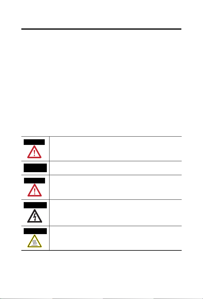
Throughout this manual, when necessary, we use notes to make you aware of safety considerations.
Identifies information about practices or circumstances that can cause an explosion in
a hazardous environment, which may lead to personal injury or death, property
damage, or economic loss.
Identifies information that is critical for successful application and understanding of
the product.
Identifies information about practices or circumstances that can lead to personal
injury or death, property damage, or economic loss. Attentions help you identify a
hazard, avoid a hazard and recognize the consequences.
Publication
Labels may be located on or inside the equipment (e.g., drive or motor) to alert people
that dangerous voltage may be present.
Labels may be located on or inside the equipment (e.g., drive or motor) to alert people
that surfaces may be dangerous temperatures.
1738-IN015C-EN-E - February 2010
Page 3

Environment and Enclosure
ATTENTION
This equipment is intended for use in overvoltage Category II
applications (as defined in IEC publication 60664-1), at altitudes
up to 2000 meters without derating.
This equipment is considered Group 1, Class A industrial
equipment according to IEC/CISPR Publication 11. Without
appropriate precautions, there may be potential difficulties
ensuring electromagnetic compatibility in other environments
due to conducted as well as radiated disturbance.
This equipment is supplied as ‘enclosed’ equipment. It should
not require additional system enclosure when used in locations
consistent with the enclosure type ratings stated in the
Specifications section of this publication. Subsequent sections of
this publication may contain additional information regarding
specific enclosure type ratings, beyond what this product
provides, that are required to comply with certain product safety
certifications.
NOTE: See NEMA Standards publication 250 and IEC
publication 60529, as applicable, for explanations of the degrees
of protection provided by different types of enclosure. Also, see
the appropriate sections in this publication, as well as the
Allen-Bradley publication 1770-4.1 (Industrial Automation
Wiring and Grounding Guidelines), for additional installation
requirements pertaining to this equipment.
3
Publication
1738-IN015C-EN-E - February 2010
Page 4

4
ATTENTION
Prevent Electrostatic Discharge
This equipment is sensitive to electrostatic discharge, which can
cause internal damage and affect normal operation. Follow these
guidelines when you handle this equipment:
• Touch a grounded object to discharge potential static.
• Wear an approved grounding wriststrap.
• Do not touch connectors or pins on component boards.
• Do not touch circuit components inside the equipment.
• If available, use a static-safe workstation.
• When not in use, store the equipment in appropriate
static-safe packaging.
About the ArmorPoint PROFIBUS Adapter
The ArmorPoint PROFIBUS adapter ships with the adapter and a
terminating base to be used with the last I/O module on the backplane. The
sealed IP67 housing of the adapter requires no enclosure. Note that it is
possible that environmental requirements other than IP67 will require an
additional appropriate housing. PROFIBUS connectors are sealed M12
(micro) style.
Publication
1738-IN015C-EN-E - February 2010
Page 5
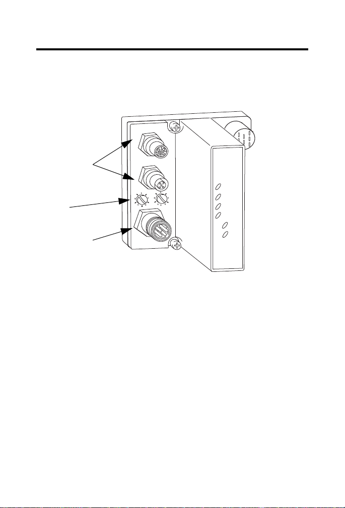
Refer to the Module Identification illustrations to guide you through the
1738-APB
Profibus Out
Profibus In
X10
X1
Adapter
Status
Profibus
Status
PointBus
Status
System
Power
Adapter
Power
PWR
Profibus DP
Network Connectors
In and Out, 5-pin,
Micro (M12),
Reverse Keyway
Station
Address
Switches
Auxiliary Power
Connector, 5-pin,
Mini
43790
installation process.
Module Identification
Install the Module
To install the module:
• Mount the adapter and I/O bases
• Wire the adapter
5
Publication
1738-IN015C-EN-E - February 2010
Page 6
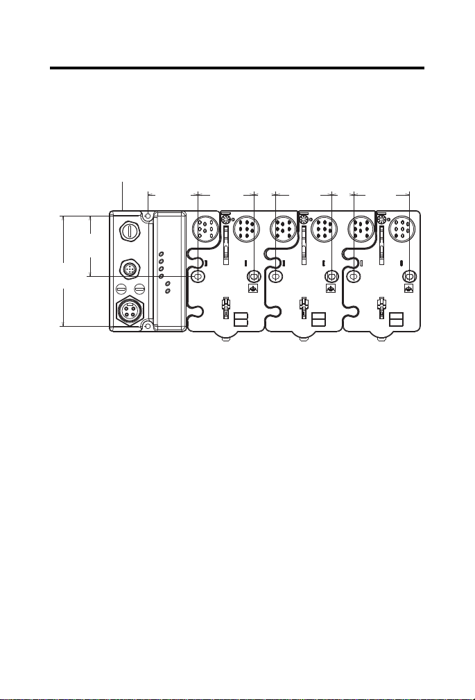
6
Adapter
102 mm
(4.02 in)
56 mm
(2.2 in)
46.25 mm
(1.8 in)
51.9 mm
(2.0 in)
20.1 mm
(0.8 in)
51.9 mm
(2.0 in)
51.9 mm
(2.0 in)
20.1 mm
(0.8 in)
43769
Mount the Adapter and I/O Bases
To mount the ArmorPoint adapter on a wall or panel, use the screw holes
provided in the ArmorPoint adapter.
Drilling Dimensions
To install the mounting base:
1. Layout the required points as shown in the Drilling Dimensions
drawing.
2. Drill the necessary holes for #8 (M4) machine or self-tapping screws.
3. Mount the adapter using #8 (M4) screws.
4. Ground the system using the ground lug connection in the I/O bases.
Note that the ground lug connection is also a mounting hole.
5. Mount the terminating base that was shipped with the adapter as the
last base in the backplane instead of the base that was shipped with
the I/O module.
Publication
1738-IN015C-EN-E - February 2010
Page 7

7
43787
Mounting Hole
Latching Mechanism
Ground Connection
31433-M
Station Address Set at 63
Terminating Bases
Set the Station Address
To set the station address, adjust the switches on the front of the module
(refer to the Module Identification illustration). Use a small blade screwdriver
to rotate the switches. Line up the small notch on the switch with the number
setting you wish to use. The two switches are most significant digit (MSD) and
least significant digit (LSD). Valid address are from 01 to 99. The module
reads the switches only when power is applied.
Set Station Address
Publication
1738-IN015C-EN-E - February 2010
Page 8

8
ATTENTION
Male In
(View into Connector)
Pin 1 - +5VBUS
Pin 2 - A-Line
Pin 3 - GNDBUS
Pin 4 - B-Line
Pin 5 - Shield
43267a
Female Out
43267b
(View into Connector)
Pin 1 - User Power Pin 2 - Adapter Power Pin 3 - Protective GND
Pin 4 - Adapter Power +
Pin 5 - User Power +
43268
GSD File Requirements
Current functionality of PROFIBUS adapters requires GSD files. These files
are easy to install and are available online at:
www.ab.com/networks/gsd/.
Wire the Adapter
Refer to the illustrations for wiring instructions for the adapter.
PROFIBUS In, Male, 5-pin Micro (M12), Reverse Keyway
PROFIBUS Out, Female, 5-pin Micro (M12), Reverse Keyway
The recommended standard cordset for the PROFIBUS auxiliary connector
is 889N-F5AFC- (x), where x equals 6, 12, or 20 feet.
Make sure all connectors and caps are securely tightened to
Publication
1738-IN015C-EN-E - February 2010
properly seal the connections against leaks and maintain IP67
requirements.
Page 9

Troubleshoot
1738-APB
Profibus Out
Profibus In
X10
X1
Adapter
Status
Profibus
Status
PointBus
Status
System
Power
Adapter
Power
PWR
Adapter Status Indicator
Profibus Status Indicator
PointBus Status Indicator
System Power Indicator
Adapter Power Indicator
43790
To help you troubleshoot the adapter, refer to the Troubleshoot with the
Indicators illustration and the individual indicator troubleshooting tables.
Troubleshoot with the Indicators
9
Publication
1738-IN015C-EN-E - February 2010
Page 10

10
Adapter Status Indicator
Refer to the table for a description of the Adapter Status indicator.
Adapter Status Indicator
State Status Description Recommended Action
Off Off or
Process in
Progress
Green Operating
Normally
Red Hardware
Check
• No power supplied.
• Hardware check is in
progress.
• Initialization is in
progress.
The adapter is operating
normally.
The adapter failed the
hardware check.
Turn the adapter on or wait until the
hardware check or initialization has
finished.
None.
Check your hardware and cycle
power to the module. If that does not
fix the fault, contact your Rockwell
Automation representative. There is
the possibility that the module needs
to be replaced.
Publication
1738-IN015C-EN-E - February 2010
Page 11

PROFIBUS Status Indicator
Refer to the table for a description of the PROFIBUS Status indicator.
PROFIBUS Status Indicator
State Status Description Recommended Action
Off Off or Bus
Offline
Green Online The Bus is online and exchanging
Flashing
Green
Red Initialization
Flashing
Red
CLEAR
Command
Received
Error or No
Module
Configuration
Error
• No power supplied.
• Bus is offline.
data.
Adapter has received a CLEAR
command from the master.
• Error in PROFIBUS
initialization.
• No modules are installed in
the backplane.
1 Hz LED Flash Rate:
• Check_Configuration telegram
rejected.
• The maximum number of
ArmorPoint I/O modules in the
master configuration was
overridden.
Turn the adapter on or
go online with the Bus.
None.
None.
Perform initialization
again or install a
module.
Check your configuration
and recycle power.
11
2 Hz LED Flash Rate:
• SetPrm telegram rejected.
• The first byte in the parameter
data does not equal zero.
• The maximum number of
parameter bytes was
overridden.
Publication
1738-IN015C-EN-E - February 2010
Page 12

12
PointBus Status Indicator
Refer to the table for a description of the PointBus Status indicator.
PointBus Status Indicator
State Status Description Recommended Action
Off Off or
Process in
Progress
Green Operating
Normally
Flashing
Red
Red Critical
Incorrect or
Missing
I/O Module
Failure
• No power supplied.
• Hardware check in
progress.
• Initialization in
progress.
The adapter is operating
normally.
• Incorrect ArmorPoint
I/O module is
installed.
• ArmorPoint I/O
module was
removed from
backplane.
Critical link failure
(BUS_OFF).
Turn the adapter on or wait until the
hardware check or initialization has
finished.
None.
Install the correct ArmorPoint I/O
module.
Check your physical network and
cycle power.
Publication
1738-IN015C-EN-E - February 2010
Page 13

System Power Indicator
Refer to the table for a description of the System Power indicator.
System Power Indicator
State Status Description Recommended Action
Off System Power
Not Applied
Green System Power
Applied
System power is not
applied.
System power (5V) is
present.
Apply power.
None.
Adapter Power Indicator
Refer to the table for a description of the Adapter Power indicator.
Adapter Power Indicator
State Status Description Recommended Action
Off Field Power
Not Applied
Green Field Power
Applied
Field power is not
applied.
Field power (24V) is
present.
Apply power.
None.
13
Publication
1738-IN015C-EN-E - February 2010
Page 14

14
Specifications
ArmorPoint PROFIBUS Adapter - 1738-APB Specifications
Specification Valu e
Expansion I/O Capacity • PROFIBUS adapter backplane current output = 1.0 A max
See the list of catalog numbers below for backplane
current consumption and the current consumption for
ArmorPoint modules connected to the ArmorPoint
PROFIBUS adapter. Verify that it is below 1.0 A.
• To extend backplane current to an additional 1.3 A, use a
1738-EP24DC Backplane Extension Power Supply.
• Use multiple 1738-EP24DC modules to reach the
maximum of 63 modules.
Cat. No. PointBus Current Requirements
1738-IB2M12 75 mA
1738-IB4xxx 75 mA
1738-IB8xxx 75 mA
1738-IV4xxx 75 mA
1738-OB2EM12 75 mA
1738-OB2EPM12 75 mA
1738-OB4Exxx 75 mA
1738-OB8Exxx 75 mA
1738-OV4EM12 75 mA
1738-OW4xxx 90 mA
1738-IE2CM12 75 mA
1738-OE2CM12 75 mA
1738-IE2VM12 75 mA
1738-OE2VM12 75 mA
1738-IA2xxx 75 mA
1738-OA2xxx 75 mA
1738-IJM23 160 mA
1738-SSIM23 110 mA
1738-IR2M12 220 mA
1738-IT2IM12 175 mA
1738-VHSC24M23 180 mA
1738-232ASCM12 75 mA
1738-485ASCM12 75 mA
Publication
1738-IN015C-EN-E - February 2010
Page 15

ArmorPoint PROFIBUS Adapter - 1738-APB Specifications
15
Field Power Bus
Nominal Voltage
Supply Voltage
Supply Current
Field Side Power
Requirements, Max
Input Overvoltage Protection Reverse polarity protected
Input Voltage Rating 24V dc nom
Isolation Voltage
(Continuous-Voltage
Withstand Rating)
Inrush Current 6 A max for 10 ms
Interruption Output voltage will stay within specifications when input
Dimensions Millimeters 112 H x 72 W x 65 D
Dimensions Inches 4.41 H x 2.83 W x 2.56 D
LED Indicators 1 green/red Adapter status
Mounting Base
Screw Torque
PointBus Output Current 1 A max @ 5V dc +5% (4.75…5.25)
Power Supply Note that in order to comply with CE Low Voltage Directives
24V dc
10…28.8V dc range
10 A max
24V dc (+20% = 28.8V dc) @ 400 mA
10…28.8V dc range
50V rms
Tested at 1250V ac rms for 60 s
drops out for 10 ms at 10V with max load
1 green/red PROFIBUS status
1 green/red PointBus status
1 green System Power (PointBus 5V power)
1 green Adapter Power (24V from field supply)
#8 screw, 7.5 lb-in. in aluminum 16 Ib-in. in steel
(LVD), you must use either a NEC Class 2, a Safety Extra Low
Voltage (SELV) or a Protected Extra Low Voltage (PELV)
power supply to power this adapter. A SELV supply must not
exceed 30V rms, 42.4V peak or 60V dc under normal
conditions and under single fault conditions. A PELV supply
has the same rating and is connected to protected earth.
Publication
1738-IN015C-EN-E - February 2010
Page 16

16
ArmorPoint PROFIBUS Adapter - 1738-APB Specifications
Power Consumption, Max 8.1 W @ 28.8V dc
Power Dissipation, Max 2.8 W @ 28.8V dc
Thermal Dissipation, Max 9.5 BTU/hr @ 28.8V dc
Weight Metric 0.36 kg
Weight Imperial 0.80 lb
Wiring Category
(1)
Use this Conductor Category information for planning conductor routing. Refer to
Publication 1770-4.1, Industrial Automation Wiring and Grounding Guidelines.
(1)
1 - on signal ports
1 - on communications ports
Environmental Specifications
Specification Value
Operating Temperature IEC 60068-2-1 (Test Ad, Operating Cold),
IEC 60068-2-2 (Test Bd, Operating Dry Heat),
IEC 60068-2-14 (Test Nb, Operating Thermal Shock):
-20…60 °C (-4…140 °F)
Storage Temperature IEC 60068-2-1 (Test Ab, Un-packaged Non-operating Cold),
IEC 60068-2-2 (Test Bb, Un-packaged Non-operating Dry Heat),
-40…85 °C (-40…185 °F)
Relative Humidity IEC 60068-2-30 (Test Db, Un-packaged Non-operating Damp
Heat):
5…95% non-condensing
Shock, Operating IEC60068-2-27 (Test Ea, Unpackaged Shock):
Shock, Non-operating IEC60068-2-27 (Test Ea, Unpackaged Shock):
Vibration IEC60068-2-6 (Test Fc, Operating):
ESD Immunity IEC 61000-4-2:
30 g
50 g
5 g @ 10…500 Hz
6 kV contact discharges
8 kV air discharges
Publication
1738-IN015C-EN-E - February 2010
Page 17

Environmental Specifications
Radiated RF Immunity IEC 61000-4-3:
10V/m with 1 kHz sine-wave 80%AM from 30…2000 MHz
10V/m with 200 Hz 50% Pulse 100%AM at 900 Mhz
10V/m with 200 Hz 50% Pulse 100%AM at 1890 Mhz
EFT/B Immunity IEC 61000-4-4:
±4 kV at 5 kHz on power ports
±2 kV at 5 kHz on communications ports
Surge Transient Immunity IEC 61000-4-5:
Conducted RF Immunity IEC 61000-4-6:
Emissions CISPR 11:
Enclosure Type Rating Meets IP65/66/67 (when marked)
±1 kV line-line(DM) and ±2 kV line-earth(CM) on power ports
±2 kV line-earth(CM) on shielded ports
10Vrms with 1 kHz sine-wave 80%AM from 150 kHz…80 MHz
Group 1, Class A
Certifications
Certification Value
Certifications:
(when product
is marked)
(1)
See the Product Certification link at www.ab.com for Declarations of Conformity,
Certificates, and other certification details.
(1)
CE European Union 2004/108/EC EMC Directive,
compliant with:
EN 61000-6-4; Industrial Emissions
EN 50082-2; Industrial Immunity
EN 61326; Meas./Control/Lab., Industrial Requirements
EN 61000-6-2; Industrial Immunity
C-Tick Australian Radiocommunications Act, compliant
with: AS/NZS CISPR 11; Industrial Emissions
17
Publication
1738-IN015C-EN-E - February 2010
Page 18

18
Notes:
Publication
1738-IN015C-EN-E - February 2010
Page 19

Notes:
19
Publication
1738-IN015C-EN-E - February 2010
Page 20

Rockwell Automation Support
Rockwell Automation provides technical information on the Web to assist you in using
its products. At http://support.rockwellautomation.com
manuals, a knowledge base of FAQs, technical and application notes, sample code and
links to software service packs, and a MySupport feature that you can customize to
make the best use of these tools.
For an additional level of technical phone support for installation, configuration, and
troubleshooting, we offer TechConnect Support programs. For more information,
contact your local distributor or Rockwell Automation representative, or visit
http://support.rockwellautomation.com
.
Installation Assistance
If you experience a problem with a hardware module within the first 24 hours of
installation, please review the information that's contained in this manual. You can also
contact a special Customer Support number for initial help in getting your module up
and running.
United States 1.440.646.3434 Monday – Friday, 8am – 5pm EST
Outside United States Please contact your local Rockwell Automation representative for
any technical support issues.
New Product Satisfaction Return
Rockwell tests all of its products to ensure that they are fully operational when shipped
from the manufacturing facility. However, if your product is not functioning, it may
need to be returned.
United States Contact your distributor. You must provide a Customer Support case
number (see phone number above to obtain one) to your distributor
in order to complete the return process.
Outside United States Please contact your local Rockwell Automation representative for
return procedure.
Allen-Bradley, Rockwell Automation, ControlLogix, RSLinx, TechConnect, ArmorPoint and FLEX I/O are
trademarks of Rockwell Automation, Inc.
Trademarks not belonging to Rockwell Automation are property of their respective companies.
, you can find technical
Publication 1738-IN015C-EN-E - February 2010
Supersedes Publication 1738-IN015B-EN-E - December 2005 Copyright © 2010 Rockwell Automation, Inc. All rights reserved. Printed in the U.S.A.
 Loading...