

Page 1

Installation Instructions
ArmorPoint I/O Modules with 8 Configurable
24V DC Points and DeviceLogix
Catalog Number(s) 1738-8CFGDLXM8,
1738-8CFGDLXM12, 1738-8CFGDLXM23
Topic Page
Important User Information 2
Environment and Enclosure 3
Prevent Electrostatic Discharge 3
About the Module 4
Mount the I/O Base 5
Install the Digital Module 6
Remove the Module From the Mounting Base 7
Wire the Module 8
Communicate with Your Module 9
Interpret the Status Indicators 16
Specifications 18
Page 2
2 ArmorPoint I/O Modules with 8 Configurable 24V DC Points and DeviceLogix
WARNING
IMPORTANT
ATTENTION
SHOCK HAZARD
BURN HAZARD
Important User Information
Solid state equipment has operational characteristics differing from those of electromechanical
equipment. Safety Guidelines for the Application, Installation and Maintenance of Solid State Controls
(Publication SGI-1.1 available from your local Rockwell Automation sales office or online at
http://literature.rockwellautomation.com) describes some important differences between solid state
equipment and hard-wired electromechanical devices. Because of this difference, and also because of
the wide variety of uses for solid state equipment, all persons responsible for applying this equipment
must satisfy themselves that each intended application of this equipment is acceptable.
In no event will Rockwell Automation, Inc. be responsible or liable for indirect or consequential damages
resulting from the use or application of this equipment.
The examples and diagrams in this manual are included solely for illustrative purposes. Because of the
many variables and requirements associated with any particular installation, Rockwell Automation, Inc.
cannot assume responsibility or liability for actual use based on the examples and diagrams.
No patent liability is assumed by Rockwell Automation, Inc. with respect to use of information, circuits,
equipment, or software described in this manual.
Reproduction of the contents of this manual, in whole or in part, without written permission of Rockwell
Automation, Inc., is prohibited.
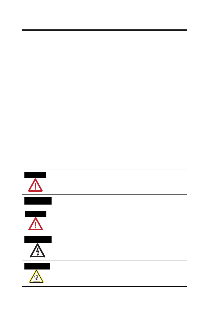
Throughout this manual, when necessary, we use notes to make you aware of safety considerations.
Identifies information about practices or circumstances that can cause an explosion
in a hazardous environment, which may lead to personal injury or death, property
damage, or economic loss.
Identifies information that is critical for successful application and understanding
of the product.
Publication
Identifies information about practices or circumstances that can lead to personal
injury or death, property damage, or economic loss. Attentions help you identify a
hazard, avoid a hazard and recognize the consequences.
Labels may be on or inside the equipment (for example, drive or motor) to alert
people that dangerous voltage may be present.
Labels may be on or inside the equipment (for example, drive or motor) to alert
people that surfaces may reach dangerous temperatures.
1738-IN027B-EN-E - February 2010
Page 3
ArmorPoint I/O Modules with 8 Configurable 24V DC Points and DeviceLogix 3
ATTENTION
ATTENTION
Environment and Enclosure
This equipment is intended for use in overvoltage Category II applications (as
defined in IEC 60664-1), at altitudes up to 2000 m (6562 ft) without derating.
This equipment is considered Group 1, Class A industrial equipment according
to IEC/CISPR 11. Without appropriate precautions, there may be potential
difficulties ensuring electromagnetic compatibility in other environments due
to conducted as well as radiated disturbance.
This equipment is supplied as enclosed equipment. It should not require
additional system enclosure when used in locations consistent with the
enclosure type ratings stated in the Specifications section of this publication.
Subsequent sections of this publication may contain additional information
regarding specific enclosure type ratings, beyond what this product provides,
that are required to comply with certain product safety certifications.
In addition to this publication, see:
• Industrial Automation Wiring and Grounding Guidelines, Allen-Bradley
publication 1770-4.1
• NEMA Standards 250 and IEC 60529, as applicable, for explanations of
the degrees of protection provided by different types of enclosure.
, for additional installation requirements.
Prevent Electrostatic Discharge
This equipment is sensitive to electrostatic discharge, which can cause
internal damage and affect normal operation. Follow these guidelines when
you handle this equipment.
• Touch a grounded object to discharge potential static.
• Wear an approved grounding wriststrap.
• Do not touch connectors or pins on component boards.
• Do not touch circuit components inside the equipment.
• Use a static-safe workstation, if available.
• Store the equipment in appropriate static-safe packaging when not in
use.
Publication
1738-IN027B-EN-E - February 2010
Page 4
4 ArmorPoint I/O Modules with 8 Configurable 24V DC Points and DeviceLogix
1738-8CFGDLXM23
24V DC
MOD
NET
0
1
2
3
4
5
6
7
1738-8CFGDLXM12
24V DC
MOD
NET
0
1
2
3
4
5
6
7
A
H
B
G
C
F
D
E
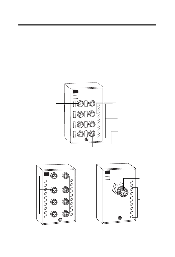
Connector M8-A
LED Indicators
44929
1738-8CFGDLXM8
Connector M8-B
Connector M8-G
Connector M8-H
1738-8CFGDLXM12
1738-8CFGDLXM23
44927
44928
LED
Indicators
LED
Indicators
Connector M8-C
Connector M8-E
Connector M8-F
Connector M8-D
M23
Connector
Connectors
M12-A...D
Connectors
M12-E...H
About the Module
The ArmorPoint I/O family consists of modular I/O modules. The sealed
IP67 housing of these modules requires no enclosure. Note that
environmental requirements other than IP67 may require an additional
appropriate housing. I/O connectors are sealed M8 (pico), M12 (micro) or
M23 styles. The mounting base ships with the module.
1738-8CFGDLXM8
24V DC
1
0
MOD
NET
3
2
5
4
7
6
0
1
2
3
4
5
6
7
Publication
1738-IN027B-EN-E - February 2010
Page 5
ArmorPoint I/O Modules with 8 Configurable 24V DC Points and DeviceLogix 5
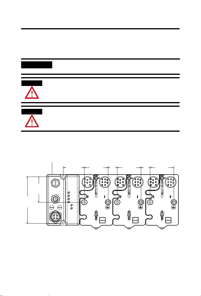
IMPORTANT
ATTENTION
ATTENTION
43769
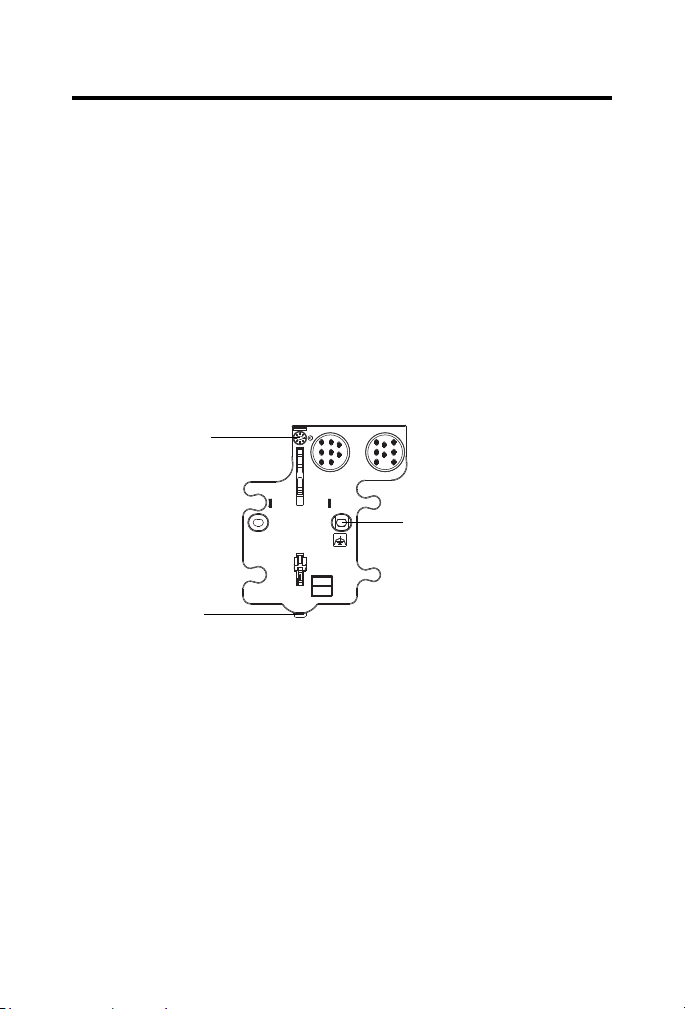
Mount the I/O Base
Mount the I/O base on a wall or panel, using the screw holes provided in the
base.
The ArmorPoint I/O module must be mounted on a grounded metal
mounting plate or other conductive surface.
Make sure all connectors and caps are securely tightened to properly seal the
connections against leaks and maintain IP enclosure type requirements.
To comply with the CE Low Voltage Directive (LVD), all connected I/O must be
powered from a source compliant with the following:
Safety Extra Low Voltage (SELV) or Protected Extra Low Voltage (PELV).
Mounting illustration for the ArmorPoint adapter with I/O bases
102 mm
(4.02 in)
56 mm
(2.2 in)
Adapter
46.25 mm
(1.8 in)
51.9 mm
(2.0 in)
20.1 mm
(0.8 in)
51.9 mm
(2.0 in)
20.1 mm
(0.8 in)
51.9 mm
(2.0 in)
Publication
1738-IN027B-EN-E - February 2010
Page 6
6 ArmorPoint I/O Modules with 8 Configurable 24V DC Points and DeviceLogix
Ground lug connection
Latching mechanism
Keyswitch
Set to position 1, for
the 1738 24V DC
input modules
43675
Install the mounting as follows:
1. Lay out the required points as shown above in the drilling dimension
drawing.
2. Drill the necessary holes for M4 (#8) machine or self-tapping screws.
3. Mount the base using M4 (#8) screws.
4. Ground the system using the ground lug connection.
The ground lug connection is also a mounting hole.
Mounting Base
Install the Digital Module
Follow the instructions to install the analog input module.
1. Using a bladed screwdriver, rotate the keyswitch on the mounting base
clockwise until the number 1 aligns with the notch in the base.
Publication
1738-IN027B-EN-E - February 2010
Page 7
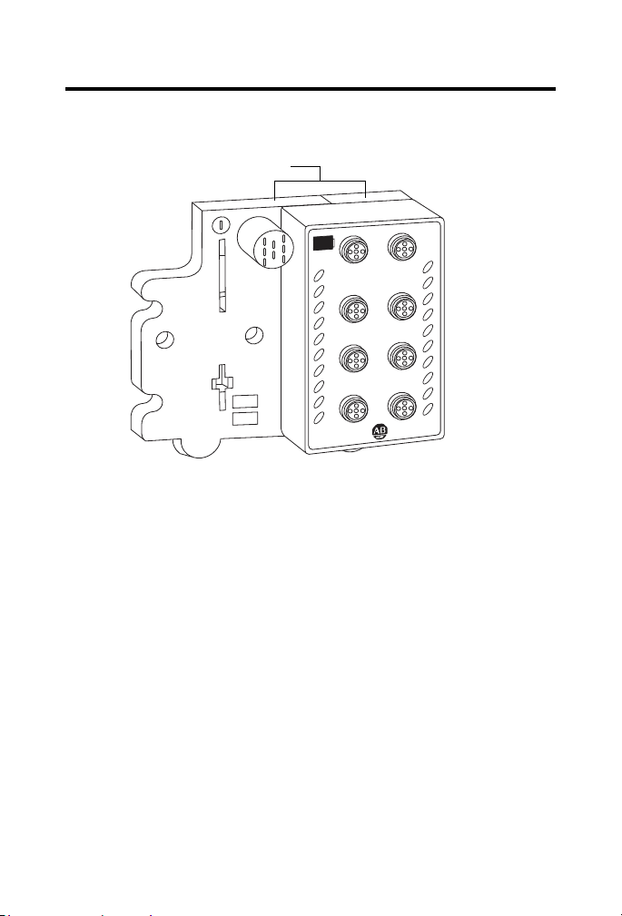
ArmorPoint I/O Modules with 8 Configurable 24V DC Points and DeviceLogix 7
Module bridges two bases
44930
1738-8CFGDLXM12 shown
2. Position the module vertically above the mounting base.
The module bridges two bases.
H
A
24V DC
MOD
NET
G
0
1
2
F
3
4
5
6
E
7
DLX
1738-8CFGDLXM12
B
C
D
3. Push the module down until it engages the latching mechanism.
You will hear a clicking sound when the module is properly engaged.
The locking mechanism locks the module to the base.
Remove the Module From the Mounting Base
Follow the instructions to remove the module from the mounting base.
1. Put a flat blade screwdriver into the slot of the orange latching
mechanism.
2. Push the screwdriver toward the I/O module to disengage the latch.
The module lifts up off the base.
3. Pull the module off the base.
Publication
1738-IN027B-EN-E - February 2010
Page 8
8 ArmorPoint I/O Modules with 8 Configurable 24V DC Points and DeviceLogix
ATTENTION
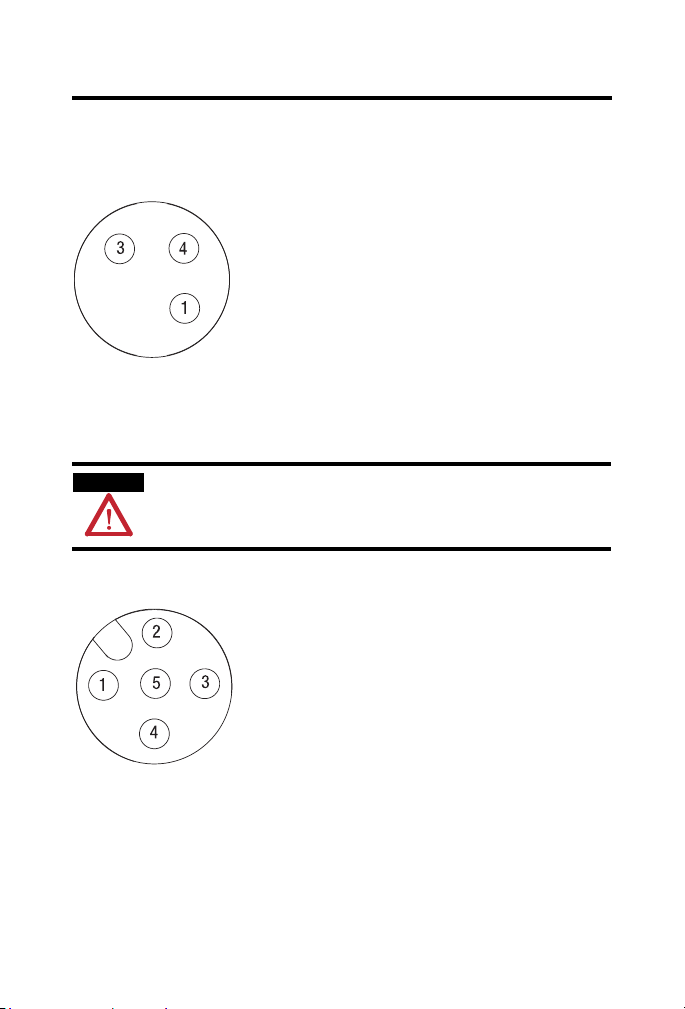
(view into connector)
Pin 1 - 24V DC
Pin 3 - Common
Pin 4 - I/O 0 (M8-A)
I/O 1 (M8-B)
I/O 2 (M8-C)
I/O 3 (M8-D)
I/O 4 (M8-E)
I/O 5 (M8-F)
I/O 6 (M8-G)
I/O 7 (M8-H)
43583
(view into connector)
Pin 1 - 24V DC
Pin 2 - Not used
Pin 3 - Common
Pin 4 - I/O 0 (M12-A)
I/O 1 (M12-B)
I/O 2 (M12-C)
I/O 3 (M12-D)
I/O 4 (M12-E)
I/O 5 (M12-F)
I/O 6 (M12-G)
I/O 7 (M12-H)
Pin 5 - Not used
43664
Wire the Module
1738-8CFGDLXM8
Make sure all connectors and caps are securely tightened to properly seal the
connections against leaks and maintain IP enclosure type requirements.
1738-8CFGDLXM12
Publication
1738-IN027B-EN-E - February 2010
Page 9

ArmorPoint I/O Modules with 8 Configurable 24V DC Points and DeviceLogix 9
3
4
5
6
7
8
9
10
11
12
2
1
(view into connector)
Pin 1 - I/O 0
Pin 2 - I/O 1
Pin 3 - I/O 2
Pin 4 - I/O 3
Pin 5 - I/O 4
Pin 6 - I/O 5
Pin 7 - I/O 6
Pin 8 - I/O 7
Pin 9 - Return (Com)
Pin 10 - Return (Com)
Pin 11 - 24V DC
Pin 12 - Chassis
43681
1738-8CFGDLXM23
Communicate with Your Module
Read this section for information about how to communicate with your
module.
I/O messages are sent to (consumed) and received from (produced) the
POINT I/O modules. These messages are mapped into the processor’s or
scanner’s memory. Each module produces 1, 8 or 20 bytes of input data based
on which produced assembly is selected. The default setup is 20 bytes. It
consumes 1, 8 or 20 bytes of I/O data (scanner Tx). The default setup is 20
bytes.
Publication
1738-IN027B-EN-E - February 2010
Page 10

10 ArmorPoint I/O Modules with 8 Configurable 24V DC Points and DeviceLogix
Default Data Map - Produced Assembly Instance 101
Message Size: 20 Bytes
Bit 76543210
Data [0] Pt 07 PT 06 Pt 05 Pt 04 Pt 03 Pt 02 Pt 01 Pt 00
Data [1] PNB 07 PNB 06 PNB 05 PNB 04 PNB 03 PNB 02 PNB 01 PNB 00
Data [2] Reserved Owned LogicEn
Data [3] PM 7 PM 6 PM 5 PM 4 PM 3 PM 2 PM 1 PM 0
Data [4] Produced Network Analog Word 0
Data [5]
Data [6] Produced Network Analog Word 1
Data [7]
Data [8] Produced Network Analog Word 2
Data [9]
Data [10] Produced Network Analog Word 3
Data [11]
Data [12] Produced Network Analog Word 4
Data [13]
Data [14] Produced Network Analog Word 5
Data [15]
Data [16] Produced Network Analog Word 6
Data [17]
Data [18] Produced Network Analog Word 7
Data [19]
Where: Pt = state of the input point
PNB = Produce Network Bit
PM = Peer Missing (each bit represents the presence of a configured peer)
LogicEN = Logic Enabled (0 = logic disabled, 1 = logic enabled)
Owned = owned by a master
When set to 0, the module is producing data without a master.
When set to 1, the module is producing while being owned by a master.
Publication
1738-IN027B-EN-E - February 2010
Page 11

ArmorPoint I/O Modules with 8 Configurable 24V DC Points and DeviceLogix 11
You can select other produced assemblies:
• Produced assembly instance 4 is the first byte of produced assembly
instance 101 (Data [0]).
• Produced assembly instance 111 is the first eight bytes of produced
assembly instance 101 (Data [0]…[7]).
In RSLogix5000, the default tags will be:
• AdapterName:SlotNumber:I.Data
• AdapterName:SlotNumber:I.LogicDefinedData
• AdapterName:SlotNumber:I.Status.LogicEnabled
• AdapterName:SlotNumber:I.Status.Owned
• AdapterName:SlotNumber:I.PeerMissing
• AdapterName:SlotNumber:I.LogicDefinedIntData[0...7]
Default Data Map - Consumed Assembly Instance 102
Message Size: 20 Bytes
Bit 76543210
Data [0] Pt 07 PT 06 Pt 05 Pt 04 Pt 03 Pt 02 Pt 01 Pt 00
Data [1] CNB 07 CNB 06 CNB 05 CNB 04 CNB 03 CNB 02 CNB 01 CNB 00
Data [2] Reserved
Data [3]
Data [4] Consume Network Analog Word 0
Data [5]
Data [6] Consume Network Analog Word 1
Data [7]
Data [8] Consume Network Analog Word 2
Data [9]
Data [10] Consume Network Analog Word 3
Data [11]
Publication
1738-IN027B-EN-E - February 2010
Page 12

12 ArmorPoint I/O Modules with 8 Configurable 24V DC Points and DeviceLogix
Default Data Map - Consumed Assembly Instance 102
Data [12] Consume Network Analog Word 4
Data [13]
Data [14] Consume Network Analog Word 5
Data [15]
Data [16] Consume Network Analog Word 6
Data [17]
Data [18] Consume Network Analog Word 7
Data [19]
Where: Pt = state of the input point
CNB = Consume Network Bit
You can select other consumed assemblies:
• Consumed assembly instance 34 is the first byte of consumed
assembly instance 102 (Data [0]).
• Consumed assembly instance 112 is the first eight bytes of consumed
assembly instance 102 (Data [0]…[7]).
In RSLogix5000, the default tags will be:
• AdapterName:SlotNumber:O.Data
• AdapterName:SlotNumber:O.LogicDefinedData
• AdapterName:SlotNumber:O.LogicDefinedIntData[0...7]
Data Map - Configuration Assembly 123
Message Size: 48 Bytes
Bit 765432 1 0
Data [0] Group Off2On Input filter
Data [1]
Data [2] Group On2Off Input filter
Data [3]
Publication
1738-IN027B-EN-E - February 2010
Page 13

ArmorPoint I/O Modules with 8 Configurable 24V DC Points and DeviceLogix 13
Data Map - Configuration Assembly 123
Data [4] FltM 7 FltM 6 FltM 5 FltM 4 FltM 3 FltM 2 FltM 1 FltM 0
Data [5] FltV 7 FltV 6 FltV 5 FltV 4 FltV 3 FltV 2 FltV 1 FltV 0
Data [6] IdIM 7 IdIM 6 IdIM 5 IdIM 4 IdIM 3 IdIM 2 IdIM 1 IdIM 0
Data [7] IdIV 7 IdIV 6 IdIV 5 IdIV 4 IdIV 3 IdIV 2 IdIV 1 IdIV 0
Data [8] Reserved RACK CFO DM MP
Data [9] Reserved
Data [10] Masterless Produce Assembly Instance (0, 4, 101, 111)
Data [11]
Data [12] Masterless Produce EPR (ms)
Data [13]
Data [14] Masterless Produce PIT (ms)
Data [15]
Data [16] Peer 0 - Slot/MacID
Data [17] Peer 0 - Consume Message Length (bytes)
Data [18] Peer 0 - EPR (ms)
Data [19]
Data [20] Peer 1 - Slot/MacID
Data [21] Peer 1 - Consume Message Length (bytes)
Data [22] Peer 1 - EPR (ms)
Data [23]
Data [24] Peer 2 - Slot/MacID
Data [25] Peer 2 - Consume Message Length (bytes)
Data [26] Peer 2 - EPR (ms)
Data [27]
Data [28] Peer 3 - Slot/MacID
Data [29] Peer 3 - Consume Message Length (bytes)
Publication
1738-IN027B-EN-E - February 2010
Page 14

14 ArmorPoint I/O Modules with 8 Configurable 24V DC Points and DeviceLogix
Data Map - Configuration Assembly 123
Data [30] Peer 3 - EPR (ms)
Data [31]
Data [32] Peer 4 - Slot/MacID
Data [33] Peer 4 - Consume Message Length (bytes)
Data [34] Peer 4 - EPR (ms)
Data [35]
Data [36] Peer 5 - Slot/MacID
Data [37] Peer 5 - Consume Message Length (bytes)
Data [38] Peer 5 - EPR (ms)
Data [39]
Data [40] Peer 6 - Slot/MacID
Data [41] Peer 6 - Consume Message Length (bytes)
Data [42] Peer 6 - EPR (ms)
Data [43]
Data [44] Peer 7 - Slot/MacID
Data [45] Peer 7 - Consume Message Length (bytes)
Publication
1738-IN027B-EN-E - February 2010
Page 15

ArmorPoint I/O Modules with 8 Configurable 24V DC Points and DeviceLogix 15
Data Map - Configuration Assembly 123
Data [46] Peer 7 – EPR (ms)
Data [47]
Where: Filter = 0...65535μs (1000 = default)
FltM = Fault Mode (0 = Fault Value (default), 1 = Hold Last State)
FltV = Fault Value (0 = OFF (default), 1 = ON
IdIM = Idle Mode (0 = Idle Value (default), 1 = Hold Last State)
IdIV = Idle Value (0 = OFF (default), 1 = ON)
RACK = Produce with Rack Assembly 4 and Consume Rack Assembly 34
(0 = Disabled (default), 1 = Enabled)
CFO = DeviceLogix Communication Fault Override of Outputs
1 = Enabled. When enabled, the DeviceLogix program will continue to control the
outputs even in the event of a communication fault.
0 = Disabled (default). When disabled, the outputs will follow the Fault and Idle
settings.
DM = Dependent Mode
MP = Masterless Produce
0 = Disabled (default), 1 - Enabled. When enabled, the module will begin
producing data at powerup and after a connection with a controller is
terminated.
EPR = Expected Packet Rate in milliseconds
PIT = Production Inhibit Time in milliseconds
Slot / MacID = Address of peer
Configuration of the 1734-8CFGDLX module must be done through
RSNetWorx for DeviceNet.
Publication
1738-IN027B-EN-E - February 2010
Page 16
16 ArmorPoint I/O Modules with 8 Configurable 24V DC Points and DeviceLogix
MOD
NET
1738-8CFGDLXM8
24V DC
0
1
2
3
4
5
6
7
0
1
2
3
4
5
6
7
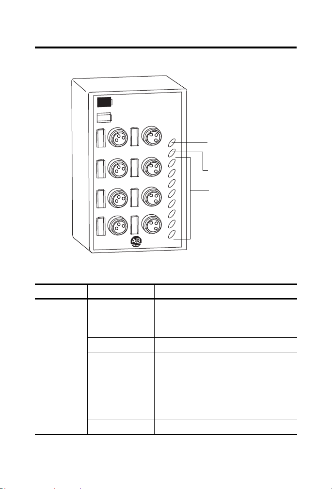
Module / Network
Status Indicator
44931
DeviceLogix Status Indicator
I/O Status Indicators
1738-8CFGDLXM8 shown
Interpret the Status Indicators
1738-8CFGDLXM8, 1738-8CFGDLXM12, 1738-8CFGDLXM23 Indicator Status
Status Description
Mod/Net status Off No power applied to device or device is auto
Publication
Green Device operating normally.
Flashing green Device is online but not connected.
Red Unrecoverable fault
Flashing red Recoverable fault – module configuration error
Flashing red/green Device is in self-test.
1738-IN027B-EN-E - February 2010
bauding.
Communication failure – duplicate node
address present or incorrect baud rate.
I/O connection fault – one or more I/O
connections in timed-out state.
Page 17

ArmorPoint I/O Modules with 8 Configurable 24V DC Points and DeviceLogix 17
1738-8CFGDLXM8, 1738-8CFGDLXM12, 1738-8CFGDLXM23 Indicator Status
Status Description
Network status Off Device is not online:
- Device has not completed dup_MAC-id test.
- Device not powered – check module status
indicator.
Green Device is online and has one or more I/O
connections in established state.
Flashing green Device is online but has no connections in
established state.
Flashing red One or more I/O connections in timed-out state.
Red Critical link failure – failed communication
device. Device detected error that prevents it
from communicating on the network.
Flashing red/green Communication faulted device – the device has
detected a network access error and is in
communication faulted state.
Device has received and accepted an Identity
Communication Faulted Request – long
protocol message.
I/O status Off I/O is inactive.
Yellow I/O is active and under control.
Flashing yellow I/O is in charging state.
Publication
1738-IN027B-EN-E - February 2010
Page 18

18 ArmorPoint I/O Modules with 8 Configurable 24V DC Points and DeviceLogix
Specifications
ArmorPoint Digital Module with Configurable 24V DC Points 1738-8CFGM8, 1738-8CFGM12, 1738-8CFGM23
Attribute Value
Number of I/O 8
On-state voltage, min 11 V DC
On-state current, min 2.0 mA
On-state current, max 5.0 mA
Off-state voltage, max 5V DC
Off-state current, min 1.5 mA
Input filter Each input independently settable in 1 ms intervals
Off to On filter, min 0 ms
Off to On filter, max 65535 ms
On to Off filter, min 0 ms
On to Off filter, max 65535 ms
Off-state current, max 15 mA
On-state voltage range, min 10V DC
On-state voltage range, max 28.8V DC
On-state voltage range, nom 24V DC
On-state voltage drop, max 0.4V DC
On-state current, max 0.5 A
Off-state leakage, max 0.5 mA
Module current, max
all outputs
Surge current, max 1.0 A for 100 ms, repeatable every 2 s
(truncated to 1 ms resolution). Default value is 1000 ms.
3.0 A
Publication
1738-IN027B-EN-E - February 2010
Page 19

ArmorPoint I/O Modules with 8 Configurable 24V DC Points and DeviceLogix 19
General Specifications
Attribute Value
Dimensions (HxWxD), approx. 120 x 72 x 42 mm
(4.72 x 2.83 x 4.25 in)
Weight, approx. 290 g (10.24 oz)
POINTBus current, max 100 mA @ 5V DC
Power dissipation, max. 2.6 W @ 28.8V DC
Thermal dissipation, max. 8.9 BTU/hr @ 28.8V DC
Isolation voltage 50V (continuous), Reinforced Insulation Type
Type tested at 2121V DC for 60 s, field-side to system
No isolation between individual channels
Field power bus voltage range 11…28.8V DC
Field power bus supply voltage,
nom
Mounting base screw torque M4 (#8) screw
Keyswitch position 1
Indicators 1 green/red module status indicator
Enclosure type rating Meets IP65/66/67/69K (when marked)
Pilot duty rating Not rated
Wiring category
(1)
Use this Conductor Category information for planning conductor routing. Refer to Industrial
Automation Wiring and Grounding Guidelines, publication 1770-4.1
(1)
24V DC
0.85 Nm (7.5 lb-in) in Aluminum
1.81 Nm (16 lb-in) in Steel
1 green/red network status indicator
8 yellow input/output status indicators
1 - on signal ports
.
Publication
1738-IN027B-EN-E - February 2010
Page 20

20 ArmorPoint I/O Modules with 8 Configurable 24V DC Points and DeviceLogix
Environmental Specifications
Attribute Value
Temperature, operating IEC60068-2-1 (Test Ad, Operating Cold),
IEC60068-2-2, (Test Bd, Operating Dry Heat),
IEC 60068-2-14 (Test Nb, Operating Thermal Shock):
-20...60 °C (-4...140 °F)
Temperature,
nonoperating
Vibration IEC 60068-2-6 (Test Fc, Operating): 5g @ 10…500 Hz
Shock, operating IEC 60068-2-27 (Test Ea, Unpackaged Shock)
Shock, nonoperating IEC 60068-2-27 (Test Ea, Unpackaged Shock)
Operating voltage 11...30V DC
Emissions CISPR 11: Group 1, Class A
ESD immunity IEC 61000-4-2:
Radiated RF immunity IEC 61000-4-3:
EFT/B immunity IEC 61000-4-4:
Surge transient
immunity
Conducted RF immunity IEC 61000-4-6:
IEC60068-2-1 (Test Ad, Non-operating Cold),
IEC60068-2-2, (Test Bd, Non-operating Dry Heat),
-40...85 °C (-40...185 °F)
30g
50g
6 kV contact discharges
8 kV air discharges
10V/m with 1 kHz sine-wave 80% AM from 30…2000 MHz
10V/m with 200 Hz 50% Pulse 100% AM at 900 MHz
10V/m with 200 Hz 50% Pulse 100% AM at 1890 MHz
3V/m with 1 kHz sine-wave 80% AM from 2000…2700 MHz
±3 kV at 5 kHz on signal ports
IEC 61000-4-5:
±1 kV line-line (DM) and ±2 kV line-earth (CM) on signal ports
10V rms with 1 kHz sine-wave 80%AM from 150 kHz...80 MHz
Publication
1738-IN027B-EN-E - February 2010
Page 21

ArmorPoint I/O Modules with 8 Configurable 24V DC Points and DeviceLogix 21
Certifications
Certification (when
product is marked)
Value
(1)
CE European Union 2004/108/EC EMC Directive, compliant with:
EN 61326-1; Meas./Control/Lab., Industrial Requirements
EN 61000-6-2; Industrial Immunity
EN 61000-6-4; Industrial Emissions
EN 61131-2; Programmable Controllers (Clause 8, Zone A & B)
C-Tick Australian Radiocommunications Act, compliant with:
AS/NZS CISPR 11; Industrial Emissions
(1)
See the Product Certification link at http://www.ab.com for Declaration of Conformity, Certificates,
and other certification details.
Publication
1738-IN027B-EN-E - February 2010
Page 22

22 ArmorPoint I/O Modules with 8 Configurable 24V DC Points and DeviceLogix
Notes:
Publication
1738-IN027B-EN-E - February 2010
Page 23

ArmorPoint I/O Modules with 8 Configurable 24V DC Points and DeviceLogix 23
Notes:
Publication
1738-IN027B-EN-E - February 2010
Page 24
Rockwell Automation Support
Rockwell Automation provides technical information on the Web to assist you in using
its products. At http://support.rockwellautomation.com
, you can find technical
manuals, a knowledge base of FAQs, technical and application notes, sample code and
links to software service packs, and a MySupport feature that you can customize to
make the best use of these tools.
For an additional level of technical phone support for installation, configuration, and
troubleshooting, we offer TechConnect support programs. For more information,
contact your local distributor or Rockwell Automation representative, or visit
http://support.rockwellautomation.com
.
Installation Assistance
If you experience a problem within the first 24 hours of installation, please review the
information that's contained in this manual. You can also contact a special Customer
Support number for initial help in getting your product up and running.
United States 1.440.646.3434
Outside United States Please contact your local Rockwell Automation representative for any
Monday – Friday, 8 a.m. – 5 p.m. EST
technical support issues.
New Product Satisfaction Return
Rockwell Automation tests all of its products to ensure that they are fully operational
when shipped from the manufacturing facility. However, if your product is not
functioning and needs to be returned, follow these procedures.
United States Contact your distributor. You must provide a Customer Support case number
Outside United States Please contact your local Rockwell Automation representative for the return
Allen-Bradley, ArmorPoint, POINT I/O, DeviceLogix, Rockwell Automation, and TechConnect are trademarks of
Rockwell Automation, Inc.
Trademarks not belonging to Rockwell Automation are property of their respective companies.
(see phone number above to obtain one) to your distributor in order to
complete the return process.
procedure.
Publication 1738-IN027B-EN-E - February 2010
Supersedes Publication 1738-IN027A-EN-E - August 2009 Copyright © 2010 Rockwell Automation, Inc. All rights reserved. Printed in Singapore.
 Loading...