

Page 1
PRO-CSW1200 12" Car Subwoofer
15 × 15 × 13
Inches (HWD)
1.25 Cubic Feet
A (2) — 15
×
15" (one with 11
16
diameter cutou t)
B (2)
15
×
12" HW
C (2) — 13
×
12" HW
F3: 46 Hz
Ripple: 0.31 dB
Excursion Limited Power Handling: 200 Watts
15 × 19 × 17
Inches (HWD)
2.25 Cubic Feet
A (2)
15
×
19" (one with 11
16
and 4
diameter cutout)
B (2) — 15
×
16
HW
C (2)
17
×
16
HW
F3: 38 Hz
Ripple: 2.0 dB
Excursion Limited Power Handling: 200 Watts
Tuning Frequency: 36 Hz
C
C
A
A
B
B
Cat. No.
40-1019
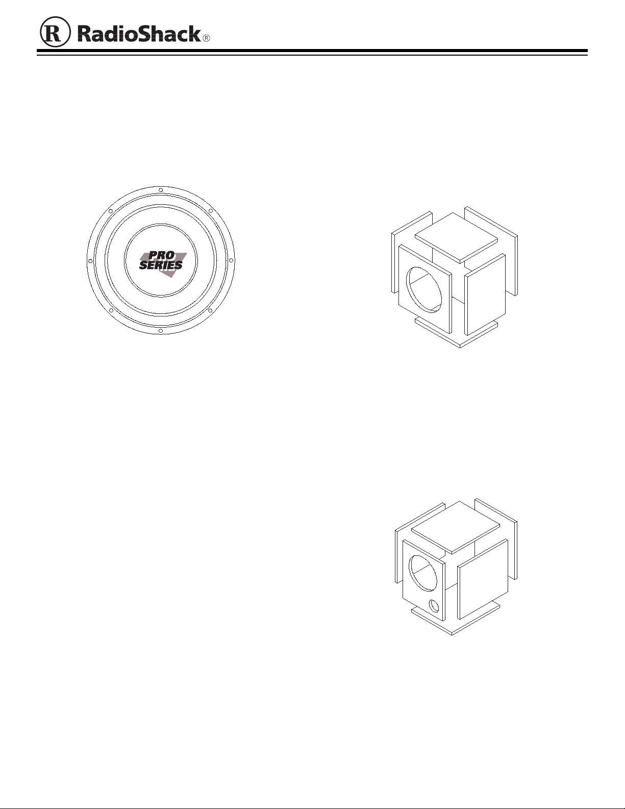
Your RadioShack PRO-CSW1200 12" Car Subwoofer
lets you increase the bass response of your vehicle’s
sound system. When mounted inside an enclosure, your
sub-woofer’s high-output, low-distortion design provides
quality, bass sound reprodu ction. The subwoofer’s long travel voice coil lets it handle high input power with ease.
To connect the subwoofer to your stereo amplifier’s
Note:
wires, you need 2 banana plugs such as Cat. No. 278306 (not supplied).
CHOOSING AN ENCLOSURE
ENCLOSURE SIZES
After you choose an enclosure type for your subwoofer,
for the best results, build the enclosure to the dimensions
recommended in this section.
Acoustic Suspension (sealed)
C
"
—
B
A
C
B
1
/
2
1
/
"
1
/
"
2
A
"
To get the best performance from your subwoofer, you
must mount it inside an enclosure. An enclosure m akes
your subwoofer more efficient and improves its sound
quality.
Some common enclosure designs are:
• Acoustic suspension (sealed)
• Ported reflex (vented)
• Single reflex bandpass (vented)
For more information about a single reflex bandpass enclosure, see “Single Reflex Bandpass (vented)” on
Page 2.
To learn more about and build an acoustic suspension or
ported reflex enclosure, we recommend you use the book
Building Speaker System s
(Cat. No. 62-1087A, available
at your local RadioShack store) along with this Owner’s
Manual. That book has com plet e in format ion ab out build ing enclosures, including obtaining construction materials, and design and construction tips.
Check with RadioShack Unlimited for a pre-built
Note:
enclosure for this subwoofer.
RadioShack is a registered trademark used by Tandy Corporation.
Ported Reflex (vented)
© 1998 Tandy Corporation.
All Rights Reserved.
—
1
/
2
"
—
1
/
"
"
1
/
"
1
/
"
2
1
/
"
2
"
2
Page 2
Single Reflex Bandpass (vented)
,
,
,
,
,
,
,
,
,,
,,
,,
,,
,,
,,
,,
,,
Speaker
Wire
Endcap
,
,
,
,
,
,
,
,
,,
,,
,,
,,
,,
,,
,,
,,
,
,
,
,
,
,
,
,
,
,
,
,
,
,
,
,
,
,
,
,
,
,
,
,
,
,
,
,
,
,
,
,
,
,
,
,
,,,,,,,,,,,,,,,,
D
C
B
A
You can mount an optional spe aker plate on your
Note:
enclosure (such as Cat. No. 274-630) to mak e it easy to
connect the subwoofe r to your stereo amplif ier. This lets
you connect the subwoofer to the plate then conne ct the
plate to your stereo amplifier.
Follow these steps to connect the subwoofer directly to
your sound system.
A
D
C
15 × 15 × 201/4 Inches (HWD)
2.5 Cubic Feet (.96 Sealed/1.54 Vented)
Inside Distance from Baffle to End Panel of
—
"
8
91/
diameter cutout)
HW
B (1)
C (2)
Sealed Side of Enclosure
—
A (2)
—
2
131/
—
24" × 15" HW (with cutout for two 4 in. vents)
D (2)
"
× 131/
—
15 × 15 Inch es
"
2
(with 91/
131/
"
2
× 241/
16
"
"
2
Tuning Frequency: 66 Hz
F3: 43–101 Hz
Ripple: .3 dB
Excursion Lim ite d Pow er Han dlin g: 20 0 Watt s
A single reflex bandpass enclosure combines the features of acoustic suspension and ported reflex designs. In
this type of enclosure, one side of the subwoofer is
mounted in an acoustic suspension en closure, while the
other side is mounted in a ported reflex enclosure.
A single reflex bandpass enclosure controls the movement of the speaker’s cone at low frequencies (like an
acoustic suspension enclosure), and has the ability to
sacrifice efficiency for deeper bass or vice versa. The frequency response of the sing le reflex bandpass enclosure
is controlled by the volume of the enclosure.
Due to the complexity of its construction, a single reflex
bandpass enclosure can be difficult to design and build. If
you are inexperienced at building enclosures, we recommend that you build an acous t ic sus pension or port ed reflex enclosure.
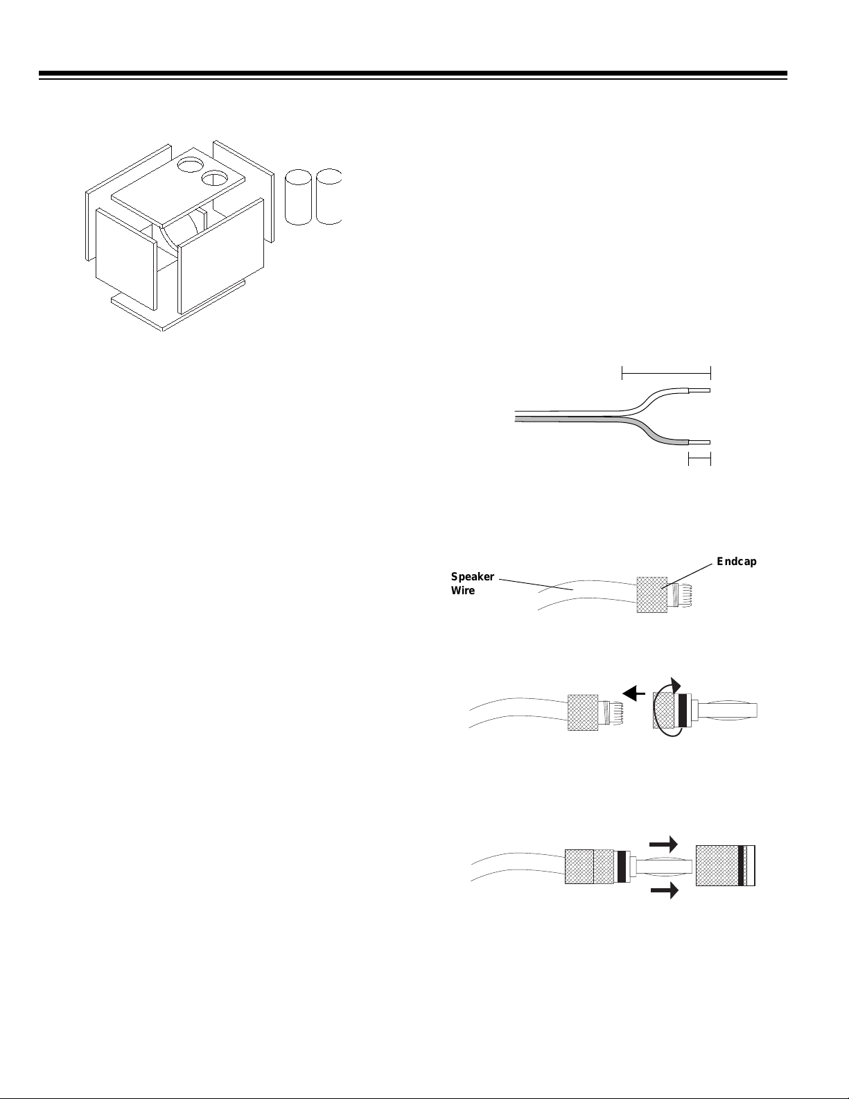
1. Run one wire from eac h of t he subwoofer’s terminals
to the stereo amplifier.
2. Separate each wire’s two conductors at both ends for
a length of about 2 inches, then strip the insulation
from the ends of each con ductor to expos e
1
/2 inch of
wire.
2 inches
2 inches
1
1/2 inch
/2 inch
3. Twist the endcap from a banana plug (not supplied)
to remove it, route one of the speaker’s wires through
the endcap, then fold the exposed wire around the
top of the endcap.
,,,,,,,
,,,,,,,
,,,,,,,
,,,,,,,
,,,,,,,
,,,,,,,
,,,,,,,
,,,,,,,
,,,,
,,,,
,,,,
,,,,
,,,,
,,,,
,,,,
,,,,
4. Twist the banana plug back onto the endcap as
shown here.
,,,,,,,
,,,,,,,
,,,,,,,
,,,,,,,
,,,,,,,
,,,,,,,
,,,,,,,
,,,,,,,
,,,,
,,,,
,,,,
,,,,
,,,,
,,,,
,,,,
,,,,
5. Repeat Steps 3 and 4 for each of the subwoofer’s
wires.
6. Press the banana plugs into the subwoofer’s terminals to connect them.
CONNECTING THE SUBWOOFER TO
YOUR STEREO AMPLIFIER
We recommend you use 12-gauge or thicker wire (such
as Cat. No. 278-1268, not supplied ) to connect the subwoofer to your stereo am plifier. For the m aximum bass
response and the best overall performance, be sure to
connect + to + and
2
to –.
–
,,,,,,,
,,,,,,,
,,,,,,,
,,,,,,,
,,,,,,,
,,,,,,,
,,,,,,,
,,,,,,,
,,,,
,,,,
,,,,
,,,,
,,,,
,,,,
,,,,
,,,,
,,,,,,,,,,,,,,
,,,,,,,,,,,,,,
,,,,,,,,,,,,,,
,,,,,,,,,,,,,,
,,,,,,,,,,,,,,
,,,,,,,,,,,,,,
,,,,,,,,,,,,,,
,,,,,,,,,,,,,,
,,,,,,,,,,,,,,
,,,,,,,,,,,,,,
Page 3

FREQUENCY RESPONSE
9
SPL(dB)
1W/1
6
0
7
94
m
91
88
85
82
79
76
73
70
20
30 40 50 60 70 80 90
Frequency (Hz)
1.25 Ft3 Acoustic Suspension 2.25 Ft3 Ported Reflex 2.5 Ft3 Single Reflex Bandpass (s=0.
SPECIFICATIONS
Frequency Range .................................................................................................................................................. 31–150 Hz
Resonant Frequency ..................................................................... ....... ....... ....... ....... .......... ....................................... 31.3 Hz
Power Handling .................................................................................................................... 200 Watts RMS/400 Watts Max
Nominal Impedance ................................................................................................................................................... 4 Ohms
Piston Area ................................................................................................................................................. 82.5 In
Magnet Weight ............................................................................................................................................................... 28 oz
Flux Density ............................................................................................................................................................. 11.52 Tm
DC Voice Coil Resistance ..................................................................................................................................... 3.41 Ohms
Voice Coil Inductance ................................................................................................................................................. 2.2 mH
Total Q Factor ............................................................................................................................................................. .57 Qts
Electrical Q Factor ...................................................................................................................... ......... .......... ......... .... .60 Qes
Mechanical Q Factor ............................................................................................................................................. 13.97 Qms
Equivalent Aco u stic Volu me .................... .......... .........................................................................................................3 .09 Ft
Mechanical Suspension Compliance .................................................................................................................... .220 mm/N
Mechanical Mass of Cone Assembly and Free Air Load ............................................................................................ 118.0 g
Mechanical Mass of Cone Assembly only .................................................................................................................. 110.9 g
Peak to Peak (maximum) Linear Excursion ............................................................................................................... .7187 In
Sensitivity .................................................................................................................................... 89.0 dB (1 Watt @ 1 Meter)
Cone ................................................................................................................................ 12 inches, Wet Look Treated Fiber
Voice Coil ............................................................................................................................. 1.5 inches, Kapton MTB Former
Surround (material of construction) ............................................................................................................... Polyether Foam
Connectors .............................................................................................................................................. 5-Way, Gold-Plated
Mounting Cutou t ...................... ......... .......... ......... ............................................................................................... 11
Mounting Depth .................... .......... ......... ........................................... ................................................................... 5
10
2
, .0532 M
1
/16 Inches
(28.01 cm)
5
/8 Inches
(14.19 cm)
2
3
Specifications are typical; individual units might vary. Specifications are subject to change and improvement without notice.
3
Page 4

Limited Ninety- D ay Warranty
This product is warr anted by RadioS hack agains t manufacturi ng defects in mater ial and work manship under nor mal use for ninety (90) days from the date of purchase from RadioShack companyowned stores and authorized RadioShack franchisees and dealers. EXCEPT AS PROVIDED
HEREIN, RadioShack MAKES NO EXPRESS WARRANTIES AND ANY IMP LIED WARRANTIES,
INCLUDING THOSE OF MERCHANTABILITY AND FIT NESS FOR A PARTICULAR PURPOSE,
ARE LIMITED IN DURATION TO THE DURATION OF THE WRITTEN LIMITED WARRANTIES
CONTAINED HEREIN. EXCEPT AS PROVIDED HEREIN, RadioShack SHALL HAVE NO LIABILITY OR RESPONSIBILITY TO CUSTOMER OR ANY O THER PERSON OR ENTITY WITH RESPECT TO ANY LIABILITY, LOSS OR DAMAGE CAUSED DIRECTLY OR INDIRECTLY BY USE
OR PERFORMANCE OF THE PRODUCT OR ARISING OUT OF ANY BREACH OF THIS WARRANTY, INCLUDING, BUT NOT LIMITED TO, ANY DA MAGES RESULTING FROM INCONVENIENCE, LOSS OF TIME, DATA, PROPERTY, REVENUE, OR PROFIT OR ANY INDIRECT,
SPECIAL, INCIDENTAL, OR CONSEQUENTIAL DAMAGES, EVEN IF RadioShack HAS BEEN ADVISED OF THE POSSIBILITY OF SUCH DAMAGES.
Some states do not allow the limitations on how long an implied warranty lasts or the exclusion of incidental or consequential damages, so the above limitations or exclusions may not apply to you.
In the event of a product defect dur ing the warranty period, take the produc t and the RadioShack
sales receipt as proof of pu rchas e date to any RadioS hack st ore. Radio Shack wi ll, at its opti on, unless otherwise provide d by law: (a) correct the defect by produc t repair w ithout cha rge for parts and
labor; (b) replac e the product with one of the same or similar design ; or (c) refund the purchase
price. All replaced par ts and products, and products on which a re fund is made, beco me the property of RadioShack . New or reconditioned parts and produ cts may be used in the perfor mance of
warranty service. R epaired or replaced parts and pr oducts are warranted for the remai nder of the
original warranty period . You will be charged for repair or replacement of the product made after the
expirati on of the warranty period.
This warranty does not cover: (a) damage or failure caused by or attributable to acts of God, abuse,
accident, misus e, impro per or ab normal usage , failure to foll ow in struct ions, im proper instal lation or
maintenance, al teration, lightning or other inciden ce of excess voltage or current; (b) any repai rs
other than those prov ided by a RadioShac k Authorized Service Fac ility; (c) consumables such as
fuses or batteri es; (d) co sme tic dama ge; (e) transpo rta tion, shi pping or insur ance cos ts; or (f) co sts
of product removal, installation, set-up service adjustment or reinstallation.
This warranty gives you specific legal rights, and you may also have other rights w hich vary from
state to state.
RadioShack Customer Relations, Dept. W, 100 Throckmorton St., Suite 600, Fort Worth, TX 76102
We Service What We Sell
3/97
RadioShack
A Division of Tandy Corporation
Fort Worth, Texas 76102
21A2652
4/98 Printed in the USA
 Loading...