


 Loading...
ORDER NO.
RRV2692
S-DV1000SW
POWERED SUBWOOFER
S-DV1000SW
THIS MANUAL IS APPLICABLE TO THE FOLLOWING MODEL(S) AND TYPE(S).
Model |
Type |
Power Requirement |
Remarks |
|
|
|
|
S-DV1000SW |
KUCXJI |
AC120V |
|
|
|
|
|
S-DV1000SW |
MYXJI |
AC220-230V |
|
|
|
|
|
S-DV1000SW |
NVXJI |
AC230V |
|
|
|
|
|
This product does not finction properly when independent ; to avoid malfunctions, be sure to connect it to the prescribed system component(s), otherwise damage may result.
Component |
System |
Service Manual |
Remarks |
|
|
|
|
DVD/CD TUNER |
XV-DV1000 |
RRV2672 |
|
|
|
|
|
POWERED SUBWOOFER |
S-DV1000SW |
RRV2692 |
This Manual |
|
|
|
|
SPEAKER SYSTEM |
S-DV1000ST |
RRV2697 |
|
|
|
|
|
For details, refer to "Important symbols for good services".
PIONEER CORPORATION 4-1, Meguro 1-chome, Meguro-ku, Tokyo 153-8654, Japan
PIONEER ELECTRONICS (USA) INC. P.O. Box 1760, Long Beach, CA 90801-1760, U.S.A.
PIONEER EUROPE NV Haven 1087, Keetberglaan 1, 9120 Melsele, Belgium
PIONEER ELECTRONICS ASIACENTRE PTE. LTD. 253 Alexandra Road, #04-01, Singapore 159936
 PIONEER CORPORATION 2002
T-ZZK OCT. 2002 printed in Japan
1 |
2 |
3 |
4 |
SAFETY INFORMATION
A
This service manual is intended for qualified service technicians; it is not meant for the casual do-it-yourselfer. Qualified technicians have the necessary test equipment and tools, and have been trained to properly and safely repair complex products such as those covered by this manual.
Improperly performed repairs can adversely affect the safety and reliability of the product and may void the warranty. If you are not qualified to perform the repair of this product properly and safely, you should not risk trying to do so and refer the repair to a qualified service technician.
WARNING
BThis product contains lead in solder and certain electrical parts contain chemicals which are known to the state of California to cause cancer, birth defects or other reproductive harm.
Health & Safety Code Section 25249.6 – Proposition 65
NOTICE
(FOR CANADIAN MODEL ONLY)
Fuse symbols  (fast operating fuse) and/or
  (slow operating fuse) on PCB indicate that replacement parts must be of identical designation.
REMARQUE
(POUR MODÈLE CANADIEN SEULEMENT)
C Les symboles de fusible  (fusible de type rapide) et/ou
  (fusible de type lent) sur CCI indiquent que les pièces de remplacement doivent avoir la même désignation.
(FOR USA MODEL ONLY)
1. SAFETY PRECAUTIONS
The following check should be performed for the continued protection of the customer and ser vice technician.
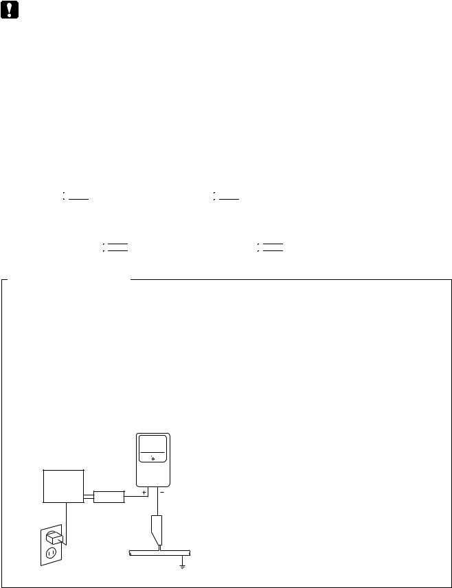
LEAKAGE CURRENT CHECK
Measure leakage current to a known earth ground (water pipe, conduit, etc.) by connecting a leakage
Dcurrent tester such as Simpson Model 229 - 2 or equivalent between the earth ground and all exposed metal parts of the appliance (input/output terminals, screwheads, metal overlays, control shaft, etc.). Plug the AC line cord of the appliance directly into a 120V AC 60 Hz outlet and turn the AC power switch on. Any current measured must not exceed 0.5 mA.
|
|
|
Reading should |
|
|
Leakage |
not be above |
|
|
0.5 mA |
|
|
|
current |
|
|
|
|
|
E |
Device |
tester |
|
|
under |
|
|
|
test |
|
|
|
Test all |
|
|
|
exposed metal |
|
|
|
surfaces |
|
|
|
Also test with |
|
|
|
plug reversed |
|
|
|
(Using AC adapter |
|
Earth |
|
plug as required) |
|
ground |
AC Leakage Test
ANY MEASUREMENTS NOT WITHIN THE LIMITS OUTLINED ABOVE ARE INDICATIVE OF A POTENTIAL SHOCK HAZARD AND MUST BE CORRECTED BEFORE RETURNING THE APPLIANCE TO THE CUSTOMER.
2. PRODUCT SAFETY NOTICE
Many electrical and mechanical parts in the appliance have special safety related characteristics. These are often not evident from visual inspection nor the protection afforded by them necessarily can be obtained by using replacement components rated for voltage, wattage, etc. Replacement parts which have these special safety characteristics are identified in this Service Manual.
Electrical components having such features are identified by marking with a  on the schematics and on the parts list in this Service Manual.
The use of a substitute replacement component which does not have the same safety characteristics as the PIONEER recommended replacement one, shown in the parts list in this Service Manual, may create shock, fire, or other hazards.
Product Safety is continuously under review and new instructions are issued from time to time. For the latest information, always consult the current PIONEER Service Manual. A subscription to, or additional copies of, PIONEER Service Manual may be obtained at a nominal charge from PIONEER.
F
2 |
|
S-DV1000SW |
|
|
1 |
2 |
|
3 |
4 |

5 |
6 |
7 |
8 |
[ Important symbols for good services ]
In this manual, the symbols shown-below indicate that adjustments, settings or cleaning should be made securely. When you find the procedures bearing any of the symbols, be sure to fulfill them:
1. Product safety
You should conform to the regulations governing the product (safety, radio and noise, and other regulations), and should keep the safety during servicing by following the safety instructions described in this manual.
2. Adjustments
To keep the original performances of the product, optimum adjustments or specification confirmation is indispensable.
In accordance with the procedures or instructions described in this manual, adjustments should be performed.
3. Cleaning
For optical pickups, tape-deck heads, lenses and mirrors used in projection monitors, and other parts requiring cleaning, proper cleaning should be performed to restore their performances.
4. Shipping mode and shipping screws
A
B
To protect the product from damages or failures that may be caused during transit, the shipping mode should be set or the shipping screws should be installed before shipping out in accordance with this manual, if necessary.
5. Lubricants, glues, and replacement parts
Appropriately applying grease or glue can maintain the product performances. But improper lubrication or applying
glue may lead to failures or troubles in the product. By following the instructions in this manual, be sure to apply the

 prescribed grease or glue to proper portions by the appropriate amount.For replacement parts or tools, the prescribed ones should be used.
C
D
E
F
|
|
|
|
|
|
|
|
|
S- |
DV1000SW |
7 |
3 |
|
5 |
6 |
|
|
|
8 |
|
1 2 3 4
CONTENTS
|
SAFETY INFORMATION..................................................................................................................................... |
2 |
|
A |
1. SPECIFICATIONS ............................................................................................................................................ |
5 |
|
2. EXPLODED VIEWS AND PARTS LIST |
6 |
||
|
|||
|
2.1 PACKING ................................................................................................................................................... |
6 |
|
|
2.2 PRODUCT APPEARANCE SECTION....................................................................................................... |
8 |
|
|
2.3 AMPLIFIER ASSY ................................................................................................................................... |
10 |
|
|
3. BLOCK DIAGRAM AND SCHEMATIC DIAGRAM .......................................................................................... |
12 |
|
|
3.1 BLOCK DIAGRAM AND OVERALL CONNECTION DIAGRAM .............................................................. |
12 |
|
|
3.2 AF and TRADE 1 ASSY........................................................................................................................... |
14 |
|
|
3.3 6CH AMP ASSY ...................................................................................................................................... |
16 |
|
|
3.4 POWER ASSY ......................................................................................................................................... |
18 |
|
|
3.5 PRIMARY ASSY ...................................................................................................................................... |
20 |
|
|
4. PCB CONNECTION DIAGRAM ..................................................................................................................... |
22 |
|
B |
4.1 AF and TRADE 1 ASSY........................................................................................................................... |
22 |
|
4.2 6CH AMP ASSY |
26 |
||
|
|||
|
4.3 POWER ASSY ......................................................................................................................................... |
28 |
|
|
4.4 PRIMARY ASSY ...................................................................................................................................... |
32 |
|
|
5. PCB PARTS LIST ........................................................................................................................................... |
34 |
|
|
6. ADJUSTMENT ............................................................................................................................................... |
37 |
|
|
7. GENERAL INFORMATION............................................................................................................................. |
37 |
|
|
7.1 DIAGNOSIS ............................................................................................................................................. |
37 |
|
|
7.1.1 PROTECTION CIRCUIT ....................................................................................................................... |
37 |
|
|
7.1.2 DISASSEMBLY ..................................................................................................................................... |
38 |
|
|
7.2 IC ............................................................................................................................................................. |
38 |
|
|
7.3 CLEANING............................................................................................................................................... |
38 |
C
D
E
F
4 |
|
S-DV1000SW |
|
|
1 |
2 |
|
3 |
4 |
5 |
6 |
1. SPECIFICATIONS
Amplifier Section
Continuous Power (RMS).......... |
75 W / channel |
(1 kHz, THD 10%, 6 Ω ) |
|
Miscellaneous
Power Requirements |
|
|
European model ......... |
220 –230 V / 50 – 60 Hz |
|
North American model |
............ 120 V / 60 Hz |
|
Power Consumption |
|
|
European model .................................. |
|
176 W |
North American model |
....................... |
180 W |
Power Consumption in standby mode ..... |
0.4 W |
|
7 |
8 |
Powered subwoofer (S-DV1000SW)
Type ............ |
Bass reflex floor type, antimagnetic |
||
Speaker ................ |
|
18 cm (7 1/16 in.) (cone type) |
|
Nominal impedence |
...................................... 6 Ω |
||
Frequency range |
............................ |
25 – 2,300 Hz |
|
Max. input ......................................... |
|
|
75 W (EIAJ) |
Dimensions ...... |
|
191 (W) x 436 (D) x 395 (H) mm |
|
|
|
|
(North American model) |
...... |
|
190 (W) x 436 (D) x 395 (H) mm |
|
|
|
|
(European model) |
Weight ............... |
|
13.0 kg (North American model) |
|
......................... |
|
|
12.9 kg (European model) |
• Specifications and design subject to possible modification without notice, due to improvements.
A
B
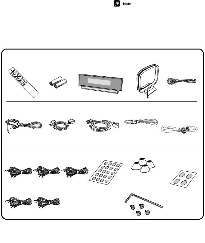
accessories
Remote control unit |
Dry cell batteries |
Display unit (AXX7142) |
AM loop antenna |
FM antenna |
C |
(KUCXJI : AXD7340) |
(sizeAA/R6P) x2 |
|
(ATB7009) |
(KUCXJI : ADH7007) |
|
(MYXJI, NVXJI : AXD7339) |
|
|
|
(MYXJI, NVXJI : ADH7010) |
|
0 
8¡
0 |
1 |
3 |
|
7 |
|
|
4 |
|
4
Control cable A |
Control cable B |
Display cable |
Video cord |
Power cord |
(ADE7064) |
(ADE7079) |
(ADE7077) |
(VDE1024) |
(KUCXJI : ADG7022) |
|
|
|
|
(MYXJI : ADG1154) |
|
|
|
|
(NVXJI : ADG1156) |
|
|
Yellow plugs |
||
Blue plugs |
Black plugs |
Gray |
|
|
Speaker cords |
|
Non-slip padsx20 |
Non-slip pads |
|
|
(subwoofer) x4 |
|||
5 mx3 (for center,front L-R speakers) |
(SEC1635) |
|||
(SEC1563) |
||||
(SDS1115) |
(SDS1116) |
(SDS1117) |
||
|
||||
|
|
European |
model only: |
|
|
|
Isolation feet x4 |
||
10 m x2 (for rear L-R speakers) |
(SXK1049) |
|||
|
|
|||
(SDS1118) |
(SDS1119) |
|
|
|
|
Operating instructions / Warranty |
Allen key wrench |
||
|
|
|
&4 screws |
|
(AEF7007)
(ABA7089)
|
|
|
|
|
|
|
|
|
S- |
DV1000SW |
7 |
5 |
|
5 |
6 |
|
|
|
8 |
|
D
E
F

1 2 3 4
2. EXPLODED VIEWS AND PARTS LIST
A
NOTES: Parts marked by "NSP" are generally unavailable because they are not in our Master Spare Parts List. |
|
The |
mark found on some component parts indicates the importance of the safety factor of the part. |
Therefore, when replacing, be sure to use parts of identical designation.  Screws adjacent to
  mark on product are used for disassembly.
 For the applying amount of lubricants or glue, follow the instructions in this manual. (In the case of no amount instructions, apply as you think it appropriate.)
2.1 PACKING
|
|
34 |
25 |
22 |
21 |
23 |
|
|
26 |
|
|
|
|
|
|
35 |
|
|
|
|
|
|
|
28 |
|
27 |
|
|
|
36 |
|
|
||
|
|
|
|
|
||
|
|
|
|
|
|
|
B |
|
37 |
|
32 |
20 |
|
|
31 |
|
|
|
||
|
|
|
|
|
|
|
|
|
|
39 |
29 |
38 |
|
|
|
|
30 |
|
19 |
33 |
|
MYXJI Only |
|
40 |
|
||
|
|
|
|
|
||
|
|
|
|
|
|
8 |
MYXJI, NVXJI |
|
7 |
Only |
|
5 |
||
11 |
||
2 |
|
C |
6 |
4 
3
24
12
10
D
18
17
9
15KUCXJI ONLY
E |
14 |
1 |
|
||
|
|
|
|
13 |
|
|
16 |
|
F
6 |
|
S-DV1000SW |
|
|
1 |
2 |
|
3 |
4 |

|
5 |
6 |
PACKING parts List |
|
|
Mark No. |
Description |
Part No. |
NSP 1 |
Accessories Set |
See Contrast table (2) |
2 |
Speaker Cords (5m : Red) |
SDS1115 |
3 |
Speaker Cords (5m : White) |
SDS1116 |
4 |
Speaker Cords (5m : Green) |
SDS1117 |
5 |
Speaker Cords (10m : Blue) |
SDS1118 |
6 |
Speaker Cords (10m : Gray) |
SDS1119 |
7 |
Sheet of large Non-Slip Pads |
SEC1563 |
8 |
Sheet of small Non-Slip Pads |
SEC1635 |
9 |
Packing Case |
SHG2449 |
10 |
Poly Bag S3 |
SHL1293 |
11 |
Accessory Set |
See Contrast table (2) |
|
(Subwoofer Isolation Feet) |
|
12 |
Top Protector |
SHA2361 |
13 |
Bottom Protector |
SHA2362 |
14 |
Protector |
SHB1097 |
15 |
Protection Sheet |
See Contrast table (2) |
16 |
Packing Case |
See Contrast table (2) |
17 |
Poly Bag S6 |
SHL1292 |
NSP 18 |
Accessories Assy |
See Contrast table (2) |
19 |
Control Cable A (Blue Plugs) |
ADE7064 |
20 |
Display cable (Gray Plugs) |
ADE7077 |
21 |
Control cable B (Black Plugs) |
ADE7079 |
|
7 |
8 |
Mark No. |
Description |
Part No. |
> 22 |
Power Cord |
See Contrast table (2) |
23 |
FM Antenna |
See Contrast table (2) |
NSP 24 |
Poly Bag |
AHG7098 |
25 |
Operating Instructions |
ARE7305 |
|
(English/French) |
|
26 |
Setup guide(English/French) |
ARE7306 |
27 |
AM Loop Antenna |
ATB7009 |
28 |
Remote Control Unit |
See Contrast table (2) |
29 |
Battery Cover |
AZN7919 |
30 |
Side Panel Replacement Screw ABA7089 |
|
31 |
Allen Key Wrench |
AEF7007 |
32 |
Video Cord (Yellow) |
VDE1024 |
NSP 33 |
Dry cell batteries (AA/R6P) |
VEM1031 |
34 |
Operating Instructions |
See Contrast table (2) |
|
(German/Italian) |
|
35 |
Setup guide (German/Italian) |
See Contrast table (2) |
36 |
Operating Instructions |
See Contrast table (2) |
|
(Spanish/Dutch) |
|
37 |
Setup guide (Spanish/Dutch) |
See Contrast table (2) |
NSP 38 |
Accessory Board |
AHB7082 |
NSP 39 |
Poly Sheet |
AHG7100 |
NSP 40 |
Screw Asy |
AXX7146 |
A
B
C
(2) CONTRAST TABLE
S-DV1000SW/KUCXJI, MYXJI and NVXJI are constructed the same except for the following:
Mark |
No. |
Symbol and Description |
S-DV1000SW/ |
S-DV1000SW/ |
S-DV1000SW/ |
|
KUCXJI |
MYXJI |
NVXJI |
||||
|
|
|
||||
|
|
|
|
|
|
|
NSP |
1 |
Accessories Set |
SME3356 |
SME3355 |
SME3355 |
|
|
11 |
Accessory Set (Subwoofer Isolation Feet) |
Not used |
SEA1596 |
SEA1596 |
|
|
15 |
Protection Sheet |
SHC1790 |
Not used |
Not used |
|
|
16 |
Packing Case |
SHG2454 |
SHG2450 |
SHG2453 |
|
NSP |
18 |
Accessories Assy |
AXX7137 |
AXX7136 |
AXX7141 |
|
> |
22 |
Power Cord |
ADG7022 |
ADG1154 |
ADG1156 |
|
|
23 |
FM Antenna |
ADH7007 |
ADH7010 |
ADH7010 |
|
|
28 |
Remote Control Unit |
AXD7340 |
AXD7339 |
AXD7339 |
|
|
34 |
Operating Instructions (German/Italian) |
Not used |
ARC7414 |
Not used |
|
|
35 |
Setup guide (German/Italian) |
Not used |
ARC7415 |
Not used |
|
|
36 |
Operating Instructions (Spanish/Dutch) |
Not used |
ARC7416 |
Not used |
|
|
37 |
Setup guide (Spanish/Dutch) |
Not used |
ARC7417 |
Not used |
|
|
|
|
|
|
|
D
E
F
|
|
|
|
|
|
|
|
|
S- |
DV1000SW |
7 |
7 |
|
5 |
6 |
|
|
|
8 |
|

|
1 |
2 |
|
|
|
3 |
4 |
|
2.2 PRODUCT APPEARANCE SECTION |
|
|
|
|||
|
|
|
RED (+) |
|
|
|
RED (+) |
A |
|
|
BLACK (–) |
IN |
|
|
WF |
KUCXJI Types |
|
|
|
|
BLACK (–) |
||
|
|
|
|
|
|
||
|
16 |
14 |
12 |
|
13 |
9 |
21 |
|
|
|
|||||
|
|
|
|
|
|||
|
FOR SP |
|
|
RED |
|
|
BLACK |
|
10 |
18 |
|
|
|
|
11 |
|
|
7 |
8 |
|
5 |
|
|
|
3 |
|
B |
4 |
|
15 |
7P |
|
|
6 |
|
|
2 |
|
17 |
1 |
22 |
23 |
||
|
|||||
|
19 |
|
|
|
20
C
D
ABSORBENT & MESH |
ABSORBENT |
|
(SMV2077) |
||
MYXJI and NVXJI Types |
||
|
||
17 |
|
|
CABINET |
|
|
19 |
|
|
E |
|
|
MESH |
|
|
(SNC1188) |
|
|
|
ABSORBENT |
|
|
(SMV2078) |
|
STAPLE X 4 |
|
|
(80/6 BEA) |
|
|
F |
|
8 |
|
S-DV1000SW |
|
|
1 |
2 |
|
3 |
4 |

|
|
5 |
6 |
PRODUCT APPEARANCE SECTION parts List |
|||
Mark No. |
Description |
Part No. |
|
NSP |
1 |
Cabinet |
See Contrast table (2) |
NSP |
2 |
Amplifier Ass'y |
See Contrast table (2) |
|
3 |
Connecting Cord |
SDF1095 |
|
4 |
Packing |
SEC1540 |
|
5 |
Packing |
SEC1634 |
NSP 6 |
Gasket |
SEE1078 |
|
|
7 |
Damper |
SER1300 |
NSP |
8 |
Stmped Serial Label |
See Contrast table (2) |
NSP 9 |
Duct Ring |
SMR1339 |
|
NSP 10 |
Cosmetic Duct |
See Contrast table (2) |
|
NSP 11 |
Paper Tube 70 |
SMR1362 |
|
NSP 12 |
Acoustic Absorbent |
SMV2077 |
|
|
7 |
8 |
|
|
Mark No. |
Description |
Part No. |
|
|
NSP 13 |
Acoustic Absorbent |
SMV2078 |
|
|
NSP 14 |
Acoustic Absorbent |
SMV2079 |
A |
|
|
||||
NSP 15 |
Mesh |
SNC1188 |
|
|
NSP 16 |
Sash |
See Contrast table (2) |
|
|
NSP 17 |
Cosmetic Baffle |
See Contrast table (2) |
|
|
18 |
Transducer |
T16EU92 |
|
|
19 |
Screw |
BPZ40P120FZB |
|
|
20 |
Screw |
See Contrast table (2) |
|
|
21 |
Screw |
BYC40P160FZB |
|
|
22 |
Screw |
See Contrast table (2) |
B |
|
23 |
Washer |
See Contrast table (2) |
||
|
(2) CONTRAST TABLE
S-DV1000SW/KUCXJI, MYXJI and NVXJI are constructed the same except for the following:
Mark |
No. |
Symbol and Description |
S-DV1000SW/ |
S-DV1000SW/ |
S-DV1000SW/ |
|
KUCXJI |
MYXJI |
NVXJI |
|
|||
|
|
|
|
|||
|
|
|
|
|
|
|
NSP |
1 |
Cabinet |
SMM1983 |
SMM1982 |
SMM1982 |
|
NSP |
2 |
Amplifier Ass'y |
AXX7133 |
AXX7132 |
AXX7140 |
|
NSP |
8 |
Stmped Serial Label |
SME3343 |
SME3333 |
SME3340 |
|
NSP |
10 |
Cosmetic Duct |
SMR1356 |
SMR1357 |
SMR1357 |
C |
NSP |
16 |
Sash |
SNH1050 |
Not used |
Not used |
|
NSP |
17 |
Cosmetic Baffle |
SNK2613 |
SNK2614 |
SNK2614 |
|
|
20 |
Screw |
BPZ45P120FMC |
Not used |
Not used |
|
|
22 |
Screw |
BYC40P200FZB |
BYC40P180FZB |
BYC40P180FZB |
|
|
23 |
Washer |
WA43F090M080 |
Not used |
Not used |
|
|
|
|
|
|
|
|
D
E
F
|
|
|
|
|
|
|
|
|
S- |
DV1000SW |
7 |
9 |
|
5 |
6 |
|
|
|
8 |
|
1 |
2 |
3 |
4 |
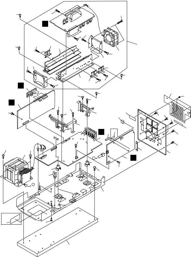
2.3 AMPLIFIER ASSY
A
24 |
34 |
C
29 
34 |
31 |
24 |
33 |
B
34 32
|
34 |
|
|
B 4 |
|
A 2 |
25 |
|
C |
||
|
||
24 |
|
7 
24
26 |
26 |
5
D
19
15
14
A
E
|
|
|
|
35 |
|
|
34 |
34 |
|
|
|
|
|
|
|
|
|
|
28 |
|
|
|
|
|
34 30 |
|
|
|
|
32 |
|
|
|
|
|
|
|
31 |
|
|
|
33 |
|
|
|
24 |
|
|
|
34 |
|
|
|
|
|
|
31 |
|
|
|
|
|
|
34 |
|
|
|
|
|
|
|
24 |
|
|
|
17 |
24 |
|
|
|
|
16 |
|
|
|
|
|
|
||
|
|
25 |
|
|
|
|
25 |
|
|
|
|
|
|
24 |
|
11 |
|
23 |
|
24 |
|
|
|
|
12 |
27 |
13 |
|
|
|
|
|
||
10 |
|
|
KUCXJI |
|
|
|
|
|
|
Only |
|
|
|
|
|
|
|
|
21 |
|
|
|
D |
6 |
20 |
|
|
|
|
|
|
|||
|
|
|
|
24 |
||
|
|
3 |
|
|
|
|
24 |
|
|
|
|
|
|
|
|
|
|
|
|
|
|
|
|
|
|
|
24 |
|
|
|
|
|
36 |
9 |
|
|
|
|
|
E |
|
|
|
A |
|
1 |
|
|
|
|
19 |
|
|
|
|
24
26
8
22 |
14 |
KUCXJI
Only
18
F
10 |
|
S-DV1000SW |
|
|
1 |
2 |
|
3 |
4 |
|
|
5 |
6 |
AMPLIFIER ASSY parts List |
|
||
Mark No. |
Description |
Part No. |
|
|
1 |
PRIMARY ASSY |
See Contrast table (2) |
|
2 |
AF ASSY |
AWU8005 |
|
3 |
POWER ASSY |
See Contrast table (2) |
|
4 |
TRADE 1 ASSY |
AWU8028 |
> |
5 |
Power Transformer |
See Contrast table (2) |
> |
6 |
Fuse (FU1) |
See Contrast table (2) |
> |
7 |
Fuse (FU4) |
See Contrast table (2) |
NSP 8 |
Chassis |
ANA7109 |
|
|
9 |
Rear Panel |
See Contrast table (2) |
|
10 |
HS Holder F |
ANG7439 |
|
11 |
HS Holder R |
ANG7440 |
|
12 |
Cushion B |
AEB7290 |
|
13 |
Spacer |
AEC1360 |
|
14 |
Card Spacer |
AEC7133 |
|
15 |
Wire Saddel |
AEC7297 |
|
16 |
Nylon Rivet |
AEC7318 |
|
17 |
Fan Cover |
AEC7427 |
|
18 |
Wood Base |
AMM7006 |
NSP 19 |
PCB Mould |
AMR1525 |
|
|
7 |
8 |
Mark No. |
Description |
Part No. |
NSP 20 |
Fuse Card |
See Contrast table (2) |
NSP 21 |
SP Label |
AAX7956 |
22 |
65 Label |
See Contrast table (2) |
NSP 23 |
Serial Paper |
RRW-168 |
24 |
Screw |
BBZ30P080FMC |
25 |
Screw |
BBZ30P200FMC |
26 |
Screw |
BYC40P140FMC |
27 |
Screw |
PSC30P080FNI |
NSP 28 |
AMP MODULE 6CH |
AXQ7242 |
29 |
6CH AMP ASSY |
AWM7720 |
30 |
DC Fan Motor |
AXM7025 |
31 |
FET Bracket |
ANG7418 |
32 |
Fan Plate |
ANG7425 |
33 |
Heat Sink |
ANH7161 |
34 |
Screw |
BBZ30P140FMC |
35 |
Screw |
BBZ30P300FZK |
NSP 36 |
USE ASSY |
• • • • • |
(2) CONTRAST TABLE
S-DV1000SW/KUCXJI, MYXJI and NVXJI are constructed the same except for the following:
Mark |
No. |
Symbol and Description |
S-DV1000SW/ |
S-DV1000SW/ |
S-DV1000SW/ |
|
KUCXJI |
MYXJI |
NVXJI |
||||
|
|
|
||||
|
|
|
|
|
|
|
|
1 |
PRIMARY ASSY |
AWU8003 |
AWU8001 |
AWU8001 |
|
|
3 |
POWER ASSY |
AWU8007 |
AWU8006 |
AWU8006 |
|
> |
5 |
Power Transformer |
ATS7342 |
ATS7341 |
ATS7341 |
|
> |
6 |
Fuse (FU1 : 6.3A) |
REK1069 |
Not used |
Not used |
|
> |
6 |
Fuse (FU1 : T3.15A) |
Not used |
REK1027 |
REK1027 |
|
> |
7 |
Fuse (FU4 : 6.3A) |
REK1069 |
Not used |
Not used |
|
> |
7 |
Fuse (FU4 : T5A) |
Not used |
REK1029 |
REK1029 |
|
|
9 |
Rear Panel |
ANC8113 |
ANC8112 |
ANC8131 |
|
NSP |
20 |
Fuse Card |
AAX2374 |
Not used |
Not used |
|
|
22 |
65 Label |
ARW7050 |
Not used |
Not used |
|
|
|
|
|
|
|
A
B
C
D
E
F
|
|
|
|
|
|
|
|
|
S- |
DV1000SW |
7 |
11 |
|
5 |
6 |
|
|
|
8 |
|

1 |
2 |
3 |
4 |
3. BLOCK DIAGRAM AND SCHEMATIC DIAGRAM
3.1 BLOCK DIAGRAM AND OVERALL CONNECTION DIAGRAM
A |
|
|
|
|
|
|
|
|
|
|
|
|
|
|
|
|
|
|
B ASSYTRADE 1 |
|
|
|
|
|
|
|
|
|
(AWU8028) |
C |
6CH AMP ASSY |
|
|
|
|
|
|
||
(AWM7720) |
|
|
|
|
|
|
|
|
|
B |
|
|
|
|
|
|
|
|
|
|
IC3301 STK402-270 |
|
|
|
|
|
|
|
|
1 |
6 |
16 |
18 |
|
|
|
|
|
|
C |
IC3401 STK402-270 |
|
|
|
|
|
|
|
|
1 |
6 |
16 |
18 |
|
|
|
|
|
|
|
|
|
|
|
|
FLP |
IC3002(1/2) |
|
|
|
|
|
|
|
|
BA4558F |
|
||
|
|
|
|
|
|
3 |
|
IC3001 M62446FP |
|
|
|
|
|
|
|
1 |
|
|
|
|
|
|
|
|
FLN 2 |
|
|
||
|
|
|
|
|
|
|
|
||
|
|
|
|
|
CP |
|
|
|
|
|
|
|
|
|
CN 3 |
1 |
17 |
|
|
|
|
|
|
|
|
2 |
|
15 |
|
|
|
|
|
|
|
IC3004(1/2) |
|
|
|
|
|
|
|
|
SLP |
BA4558F |
11 |
31 |
|
|
|
|
|
|
3 |
|
33 |
||
|
|
|
|
|
SLN |
|
9 |
||
|
|
|
|
|
2 |
1 |
34 |
||
|
|
|
|
|
|
IC3003(1/2) |
36 |
||
|
|
|
|
|
|
|
|||
D |
|
|
|
|
|
|
BA4558F |
6 |
|
|
|
SWP |
|
|
|||||
|
|
5 |
|
|
|
||||
|
|
|
SWN |
7 |
|
|
|||
|
|
|
|
|
|
||||
|
|
|
|
|
|
6 |
|
|
|
|
|
|
|
|
|
IC3004(2/2) |
|
||
|
|
|
|
|
|
|
|
||
|
|
|
IC3101(1/2) |
|
|
BA4558F |
|
|
|
|
|
|
|
|
|
|
|
||
|
|
|
UPC4570 |
|
|
|
|
|
|
|
|
|
5 |
|
|
|
|
|
|
|
|
|
7 |
|
|
|
|
|
|
|
|
|
6 |
|
|
|
|
|
|
|
|
|
3 |
|
|
|
|
|
|
|
|
|
1 |
|
|
|
|
|
|
|
|
|
2 |
|
|
|
|
|
|
|
|
|
IC3103(1/2) |
|
|
|
|
|
|
|
|
|
BA4558F |
|
|
|
5 |
|
|
|
|
|
|
|
5 |
7 |
|
|
|
|
|
|
3 |
7 |
6 |
|
|
||
|
|
|
6 |
|
|
|
|||
|
|
|
1 |
|
|
IC3103(2/2) |
|
||
|
|
|
2 |
|
IC3104(1/2) |
|
|||
|
|
|
|
BA4558F |
|
|
|||
|
|
|
IC3104(2/2) |
|
|
||||
|
|
|
BA4558F |
|
|
|
|||
E |
|
|
BA4558F |
|
|
|
|
|
|
|
|
5 |
|
|
|
|
|
|
|
|
|
|
|
|
|
|
|
|
|
|
|
|
7 |
|
|
|
|
|
|
|
|
|
6 |
|
|
|
|
|
|
|
|
|
IC3102(1/2) |
|
|
|
|
|
|
|
|
|
BA4558F |
|
|
|
|
|
|
|
|
|
|
|
|
|
AF ASSY |
|
|
|
|
|
|
|
|
A (AWU8005) |
|
||
F |
|
|
|
|
|
|
|
|
|
12 |
|
|
S-DV1000SW |
|
|
|
|||
|
1 |
|
2 |
|
|
|
|
3 |
4 |
Loading...