


 Loading...
Operating Instructions
audio/video multi-channel receiver
SC-LX82 SC-LX72
IMPORTANT
CAUTION
RISK OF ELECTRIC SHOCK
DO NOT OPEN
The lightning flash with arrowhead symbol, within an equilateral triangle, is intended to alert the user to the presence of uninsulated “dangerous voltage” within the product’s enclosure that may be of sufficient magnitude to constitute a risk of electric shock to persons.
CAUTION:
TO PREVENT THE RISK OF ELECTRIC SHOCK, DO NOT REMOVE COVER (OR BACK). NO USER-SERVICEABLE PARTS INSIDE. REFER SERVICING TO QUALIFIED SERVICE PERSONNEL.
The exclamation point within an equilateral triangle is intended to alert the user to the presence of important operating and maintenance (servicing) instructions in the literature accompanying the appliance.
D3-4-2-1-1_A1_En
Replacement and mounting of an AC plug on the power supply cord of this unit should be performed only by qualified service personnel.
IMPORTANT: THE MOULDED PLUG
This appliance is supplied with a moulded three pin mains plug for your safety and convenience. A 5 amp fuse is fitted in this plug. Should the fuse need to be replaced, please ensure that the replacement fuse has a rating of 5 amps and that it is approved by ASTA or BSI to BS1362.
Check for the ASTA mark |
or the BSI mark |
on the body of the fuse. |
If the plug contains a removable fuse cover, you must ensure that it is refitted when the fuse is replaced. If you lose the fuse cover the plug must not be used until a replacement cover is obtained. A replacement fuse cover can be obtained from your local dealer.
If the fitted moulded plug is unsuitable for your socket outlet, then the fuse shall be removed and the plug cut off and disposed of safely. There is a danger of severe electrical shock if the cut off plug is inserted into any 13 amp socket.
If a new plug is to be fitted, please observe the wiring code as shown below. If in any doubt, please consult a qualified electrician.
IMPORTANT: The wires in this mains lead are coloured in accordance with the following code: Blue : Neutral Brown : Live
As the colours of the wires in the mains lead of this appliance may not correspond with the coloured markings identifying the terminals in your plug, proceed as follows ;
The wire which is coloured BLUE must be connected to the terminal which is marked with the letter N or coloured BLACK.
The wire which is coloured BROWN must be connected to the terminal which is marked with the letter L or coloured RED.
How to replace the fuse: Open the fuse compartment with a screwdriver and replace the fuse.
D3-4-2-1-2-2_B_En
WARNING
This equipment is not waterproof. To prevent a fire or shock hazard, do not place any container filled with liquid near this equipment (such as a vase or flower pot) or expose it to dripping, splashing, rain or moisture.
WARNING
Before plugging in for the first time, read the following section carefully.
The voltage of the available power supply differs according to country or region. Be sure that the power supply voltage of the area where this unit will be used meets the required voltage (e.g., 230 V or 120 V) written on the rear panel.
Operating Environment
Operating environment temperature and humidity: +5 °C to +35 °C (+41 °F to +95 °F); less than 85 %RH (cooling vents not blocked)
Do not install this unit in a poorly ventilated area, or in locations exposed to high humidity or direct sunlight (or strong artificial light)
D3-4-2-1-7c*_A1_En
Information for users on collection and disposal of old equipment and used batteries
Symbol for |
These symbols on the products, packaging, and/or accompanying documents mean |
|||||||||
equipment |
that used electrical and electronic products and batteries should not be mixed with |
|||||||||
|
|
|
|
|
|
|
|
|
|
general household waste. |
|
|
|
|
|
|
|
|
|
|
For proper treatment, recovery and recycling of old products and used batteries, |
|
|
|
|
|
|
|
|
|
|
|
|
|
|
|
|
|
|
|
|
|
please take them to applicable collection points in accordance with your national |
|
|
|
|
|
|
|
|
|
|
legislation. |
|
|
|
|
|
|
|
|
|
|
By disposing of these products and batteries correctly, you will help to save valuable |
|
|
|
|
|
|
|
|
|
|
|
Symbol examples |
resources and prevent any potential negative effects on human health and the |
|||||||||
for batteries |
environment which could otherwise arise from inappropriate waste handling. |
|||||||||
|
|
|
|
|
|
|
|
|
|
For more information about collection and recycling of old products and batteries, |
|
|
|
|
|
|
|
|
|
|
please contact your local municipality, your waste disposal service or the point of sale |
|
|
|
|
|
|
|
|
|
|
where you purchased the items. |
|
|
|
|
|
|
|
|
|
|
These symbols are only valid in the European Union. |
|
|
|
|
|
|
|
|
|
|
For countries outside the European Union: |
|
|
|
|
|
|
|
|
|
|
If you wish to discard these items, please contact your local authorities or dealer and |
|
|
|
|
|
|
|
|
|
|
ask for the correct method of disposal. |
Pb
K058a_A1_En
WARNING
To prevent a fire hazard, do not place any naked flame sources (such as a lighted candle) on the equipment.
VENTILATION CAUTION
When installing this unit, make sure to leave space around the unit for ventilation to improve heat radiation (at least 20 cm at top, 10 cm at rear, and 20 cm at each side).
WARNING
Slots and openings in the cabinet are provided for ventilation to ensure reliable operation of the product, and to protect it from overheating. To prevent fire hazard, the openings should never be blocked or covered with items (such as newspapers, table-cloths, curtains) or by operating the equipment on thick carpet or a bed.
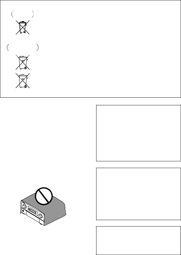
If the AC plug of this unit does not match the AC outlet you want to use, the plug must be removed and appropriate one fitted. Replacement and mounting of an AC plug on the power supply cord of this unit should be performed only by qualified service personnel. If connected to an AC outlet, the cut-off plug can cause severe electrical shock. Make sure it is properly disposed of after removal.
The equipment should be disconnected by removing the mains plug from the wall socket when left unused for a long period of time (for example, when on vacation).
D3-4-2-2-1a_A1_En
CAUTION
The STANDBY/ON switch on this unit will not completely shut off all power from the AC outlet. Since the power cord serves as the main disconnect device for the unit, you will need to unplug it from the AC outlet to shut down all power. Therefore, make sure the unit has been installed so that the power cord can be easily unplugged from the AC outlet in case of an accident. To avoid fire hazard, the power cord should also be unplugged from the AC outlet when left unused for a long period of time (for example, when on vacation).
This product is for general household purposes. Any failure due to use for other than household purposes (such as long-term use for business purposes in a restaurant or use in a car or ship) and which requires repair will be charged for even during the warranty period.

Thank you for buying this Pioneer product. Please read through these operating instructions so you will know how to operate your model properly. After you have finished reading the instructions, put them away in a safe place for future reference.
Contents
Flow of settings on the receiver . . . . . 7
01 Before you start
Our philosophy . . . . . . . . . . . . . . . . . . . . . . . . . . . . . . . 8 Features . . . . . . . . . . . . . . . . . . . . . . . . . . . . . . . . . . . . 8 Checking what’s in the box. . . . . . . . . . . . . . . . . . . . . . 9 Installing the receiver . . . . . . . . . . . . . . . . . . . . . . . . . 10 Loading the batteries . . . . . . . . . . . . . . . . . . . . . . . . . 10
Operating range of remote control unit . . . . . . . . . . . 10
02 Controls and displays
Remote control (In case of SC-LX82). . . . . . . . . . . . . . 11 Remote control (In case of SC-LX72). . . . . . . . . . . . . . 14
Front panel . . . . . . . . . . . . . . . . . . . . . . . . . . . . . . . . . 16 Display . . . . . . . . . . . . . . . . . . . . . . . . . . . . . . . . . . . . 17
03 Connecting your equipment
Rear panel . . . . . . . . . . . . . . . . . . . . . . . . . . . . . . . . . 19
Determining the speakers’ application . . . . . . . . . . . . 21 Other speaker connection . . . . . . . . . . . . . . . . . . . . 21
Placing the speakers . . . . . . . . . . . . . . . . . . . . . . . . . 22 THX speaker system setup . . . . . . . . . . . . . . . . . . . . 22
Some tips for improving sound quality . . . . . . . . . . . 22
Connecting the speakers . . . . . . . . . . . . . . . . . . . . . . 23
Installing your speaker system . . . . . . . . . . . . . . . . . . 24 Standard 5.1/6.1/7.1-channel surround
connections . . . . . . . . . . . . . . . . . . . . . . . . . . . . . . . 24 Bi-amping your speakers . . . . . . . . . . . . . . . . . . . . . 25 Bi-wiring your speakers . . . . . . . . . . . . . . . . . . . . . . 25
Selecting the Surr Back system . . . . . . . . . . . . . . . . . 26
ZONE 2 setup . . . . . . . . . . . . . . . . . . . . . . . . . . . . . . 26 Speaker B setup. . . . . . . . . . . . . . . . . . . . . . . . . . . . 26 Bi-Amping setup . . . . . . . . . . . . . . . . . . . . . . . . . . . 26
About the audio connection . . . . . . . . . . . . . . . . . . . . 26
About the video converter. . . . . . . . . . . . . . . . . . . . . . 27
Connecting your TV and playback components . . . . . 28
Connecting using HDMI . . . . . . . . . . . . . . . . . . . . . 28
Connecting your DVD player with
no HDMI output . . . . . . . . . . . . . . . . . . . . . . . . . . . . 29
Connecting your TV with no HDMI input . . . . . . . . . 30 Connecting an HDD/DVD recorder, VCR and
other video sources . . . . . . . . . . . . . . . . . . . . . . . . . . 32
Connecting a satellite/cable receiver or
other set-top box. . . . . . . . . . . . . . . . . . . . . . . . . . . . . 33
Connecting the multichannel analog inputs. . . . . . . . 33 Connecting other audio components . . . . . . . . . . . . . 34 About the WMA9 Pro decoder . . . . . . . . . . . . . . . . . 34 Connecting additional amplifiers . . . . . . . . . . . . . . . . 35 Connecting AM/FM antennas. . . . . . . . . . . . . . . . . . . 35 Connecting external antennas . . . . . . . . . . . . . . . . . 36
MULTI-ZONE setup . . . . . . . . . . . . . . . . . . . . . . . . . . . 37
Making MULTI-ZONE connections . . . . . . . . . . . . . . 37
Connecting an IR receiver . . . . . . . . . . . . . . . . . . . . . 39
Operating other Pioneer components with
this unit’s sensor . . . . . . . . . . . . . . . . . . . . . . . . . . . . 39
4
Switching components on and off using
the 12 volt trigger . . . . . . . . . . . . . . . . . . . . . . . . . . . . 40
Connecting a PC for Advanced MCACC output . . . . . 40 Connecting an HDMI-equipped component to
the front panel input. . . . . . . . . . . . . . . . . . . . . . . . . . 41 Connecting an iPod . . . . . . . . . . . . . . . . . . . . . . . . . . 42 Connecting a USB device. . . . . . . . . . . . . . . . . . . . . . 42 Plugging in the receiver . . . . . . . . . . . . . . . . . . . . . . . 43
04 Basic Setup
Changing the OSD display language
(OSD Language). . . . . . . . . . . . . . . . . . . . . . . . . . . . . 44
Automatically setting up for surround sound
(Auto MCACC & Full Band Phase Control) . . . . . . . . . 45 Problems when using the Auto MCACC Setup . . . . 47
The Input Setup menu . . . . . . . . . . . . . . . . . . . . . . . . 47
Input function default and possible settings . . . . . . 48
05 Basic playback
Playing a source. . . . . . . . . . . . . . . . . . . . . . . . . . . . . 49
Playing a source with HDMI connection . . . . . . . . . 49 Selecting the multichannel analog inputs . . . . . . . . 50
Playing an iPod . . . . . . . . . . . . . . . . . . . . . . . . . . . . . 50
Playing back audio files stored on an iPod. . . . . . . . 50
Playing a USB device . . . . . . . . . . . . . . . . . . . . . . . . . 52
Playing back audio files stored on a USB
memory device. . . . . . . . . . . . . . . . . . . . . . . . . . . . . 52
Playing back photo files stored on a USB
memory device. . . . . . . . . . . . . . . . . . . . . . . . . . . . . 53
About playable file formats . . . . . . . . . . . . . . . . . . . 54
Listening to the radio . . . . . . . . . . . . . . . . . . . . . . . . . 55 Improving FM sound . . . . . . . . . . . . . . . . . . . . . . . . 55 Using the noise cut mode . . . . . . . . . . . . . . . . . . . . 55 Using Neural THX . . . . . . . . . . . . . . . . . . . . . . . . . . 55
Tuning directly to a station. . . . . . . . . . . . . . . . . . . . 55
Saving station presets . . . . . . . . . . . . . . . . . . . . . . . 55 Naming station presets . . . . . . . . . . . . . . . . . . . . . . 56
Listening to station presets . . . . . . . . . . . . . . . . . . . 56
An introduction to RDS . . . . . . . . . . . . . . . . . . . . . . 56
En

06 Listening to your system
Auto playback . . . . . . . . . . . . . . . . . . . . . . . . . . . . . . 58
Listening in surround sound . . . . . . . . . . . . . . . . . . . 59
Standard surround sound . . . . . . . . . . . . . . . . . . . . 59
Using the Home THX modes . . . . . . . . . . . . . . . . . . 60 Using the Advanced surround effects . . . . . . . . . . . 60
Listening in stereo . . . . . . . . . . . . . . . . . . . . . . . . . . . 61
Using Front Stage Surround Advance . . . . . . . . . . . . 62
Using Stream Direct . . . . . . . . . . . . . . . . . . . . . . . . . 62
Using surround back channel processing . . . . . . . . . 63 Using the Virtual Surround Back mode . . . . . . . . . . 63 Setting the Up Mix function . . . . . . . . . . . . . . . . . . . . 64
Selecting MCACC presets . . . . . . . . . . . . . . . . . . . . . 64 Choosing the input signal . . . . . . . . . . . . . . . . . . . . . 65
Better sound using Phase Control and
Full Band Phase Control . . . . . . . . . . . . . . . . . . . . . . 65 Using Phase Control . . . . . . . . . . . . . . . . . . . . . . . . 65
Using Full Band Phase Control . . . . . . . . . . . . . . . . 66
07 Playback with HOME MEDIA GALLERY inputs
Enjoying the Home Media Gallery . . . . . . . . . . . . . . . 68 Features of Home Media Gallery . . . . . . . . . . . . . . . . 68 Steps to enjoy the Home Media Gallery . . . . . . . . . . . 68
Playing back audio files on the network and
listening to Internet radio stations. . . . . . . . . . . . . . 68 Connecting to the network through LAN interface. . . 69
Introduction. . . . . . . . . . . . . . . . . . . . . . . . . . . . . . . . 69 About network playback. . . . . . . . . . . . . . . . . . . . . . . 70 Windows Media Player . . . . . . . . . . . . . . . . . . . . . . 70 Windows Media DRM . . . . . . . . . . . . . . . . . . . . . . . 70 DLNA . . . . . . . . . . . . . . . . . . . . . . . . . . . . . . . . . . . 70
Content playable over a network . . . . . . . . . . . . . . . 70 About playback behavior over a network . . . . . . . . . 70 Authorizing this receiver . . . . . . . . . . . . . . . . . . . . . 70 Playback with Home Media Gallery . . . . . . . . . . . . . . 71
Playing back audio files stored on components
on the network . . . . . . . . . . . . . . . . . . . . . . . . . . . . 72
Listening to Internet radio stations . . . . . . . . . . . . . 72 Listening to Neural Music Direct. . . . . . . . . . . . . . . 74 Playing back your favorite songs . . . . . . . . . . . . . . . 74 About playable file formats . . . . . . . . . . . . . . . . . . . 75 Advanced operations for Internet radio . . . . . . . . . . . 76 Saving Internet radio stations . . . . . . . . . . . . . . . . . 76 Retrieving saved Internet radio stations. . . . . . . . . . 76
Setting up the network. . . . . . . . . . . . . . . . . . . . . . . . 76
Checking the network settings . . . . . . . . . . . . . . . . 78
Software update . . . . . . . . . . . . . . . . . . . . . . . . . . . 78 Glossary. . . . . . . . . . . . . . . . . . . . . . . . . . . . . . . . . . . 79
08 KURO LINK
Making the KURO LINK connections. . . . . . . . . . . . . 81 Cautions on the KURO LINK function . . . . . . . . . . . 81 About connections with a product of a different
brand that supports the KURO LINK function . . . . . 82
KURO LINK Setup . . . . . . . . . . . . . . . . . . . . . . . . . . . 82 Setting the PQLS function . . . . . . . . . . . . . . . . . . . . . 83
Before using synchronization . . . . . . . . . . . . . . . . . . 84
Synchronized amp mode . . . . . . . . . . . . . . . . . . . . . . 84
Synchronized amp mode operations . . . . . . . . . . . . 84 Canceling synchronized amp mode . . . . . . . . . . . . 84
09 Using other functions
Setting the Audio options . . . . . . . . . . . . . . . . . . . . . 85
About the SRC (Sampling Rate Converter)
(SC-LX82 only) . . . . . . . . . . . . . . . . . . . . . . . . . . . . . 86 Setting the Video options. . . . . . . . . . . . . . . . . . . . . . 87
Switching the speaker system . . . . . . . . . . . . . . . . . . 88 Using the MULTI-ZONE controls . . . . . . . . . . . . . . . . 88 Making an audio or a video recording . . . . . . . . . . . . 89 Reducing the level of an analog signal . . . . . . . . . . . 90
Using the sleep timer . . . . . . . . . . . . . . . . . . . . . . . . 90 Dimming the display . . . . . . . . . . . . . . . . . . . . . . . . . 90
Switching the HDMI output . . . . . . . . . . . . . . . . . . . . 91 Checking your system settings . . . . . . . . . . . . . . . . . 91
Resetting the system . . . . . . . . . . . . . . . . . . . . . . . . . 92 Default system settings. . . . . . . . . . . . . . . . . . . . . . 92
10 Controlling the rest of your system (In case of SC-LX82)
Operating multiple receivers . . . . . . . . . . . . . . . . . . . 93 Setting the remote to control other components . . . . 93 Selecting preset codes directly . . . . . . . . . . . . . . . . . 93 Programming signals from other remote controls . . . 94 Erasing one of the remote control button settings . . . 95 Resetting the remote control presets. . . . . . . . . . . . . 95
Confirming preset codes . . . . . . . . . . . . . . . . . . . . . . 95
Renaming input function names . . . . . . . . . . . . . . . . 95
Direct function . . . . . . . . . . . . . . . . . . . . . . . . . . . . . 96
Multi Operation and System Off . . . . . . . . . . . . . . . . 96 Programming a multi-operation or
a shutdown sequence . . . . . . . . . . . . . . . . . . . . . . . 96 Using multi operations . . . . . . . . . . . . . . . . . . . . . . 97 Using System off . . . . . . . . . . . . . . . . . . . . . . . . . . . 97
Controls for the components . . . . . . . . . . . . . . . . . . . 98
10 Controlling the rest of your system (In case of SC-LX72)
Operating multiple receivers . . . . . . . . . . . . . . . . . . 100 Setting the remote to control other components . . . 100 Selecting preset codes directly . . . . . . . . . . . . . . . . 100 Programming signals from other remote controls . . . 101 Erasing the remote control button settings . . . . . . . 101 Multi Operation and System Off . . . . . . . . . . . . . . . 102
Programming a multi-operation . . . . . . . . . . . . . . 102
Using multi operations . . . . . . . . . . . . . . . . . . . . . 102 Using System off . . . . . . . . . . . . . . . . . . . . . . . . . . 103
Resetting the remote control presets. . . . . . . . . . . . 103
Default preset codes . . . . . . . . . . . . . . . . . . . . . . . 103 Controls the components . . . . . . . . . . . . . . . . . . . . 103
5
En

11 The Advanced MCACC menu
Making receiver settings from the Advanced
MCACC menu . . . . . . . . . . . . . . . . . . . . . . . . . . . . . 106
Automatic MCACC (Expert) . . . . . . . . . . . . . . . . . . . 107
Manual MCACC setup . . . . . . . . . . . . . . . . . . . . . . . 109 Fine Channel Level . . . . . . . . . . . . . . . . . . . . . . . . . 110 Fine Speaker Distance . . . . . . . . . . . . . . . . . . . . . . 111 Standing Wave. . . . . . . . . . . . . . . . . . . . . . . . . . . . 111
Acoustic Calibration EQ Adjust . . . . . . . . . . . . . . . 112 Acoustic Calibration EQ Professional. . . . . . . . . . . 112 Precision Distance (SC-LX82 only) . . . . . . . . . . . . . 114
Checking MCACC Data . . . . . . . . . . . . . . . . . . . . . . 115 Speaker Setting . . . . . . . . . . . . . . . . . . . . . . . . . . . 116 Channel Level. . . . . . . . . . . . . . . . . . . . . . . . . . . . . 116 Speaker Distance . . . . . . . . . . . . . . . . . . . . . . . . . . 116 Standing Wave. . . . . . . . . . . . . . . . . . . . . . . . . . . . 116 Acoustic Cal EQ . . . . . . . . . . . . . . . . . . . . . . . . . . . 117 Group Delay . . . . . . . . . . . . . . . . . . . . . . . . . . . . . . 117 Output PC . . . . . . . . . . . . . . . . . . . . . . . . . . . . . . . 117
Data Management . . . . . . . . . . . . . . . . . . . . . . . . . . 118 Renaming MCACC presets . . . . . . . . . . . . . . . . . . 118
Copying MCACC preset data . . . . . . . . . . . . . . . . . 118
Clearing MCACC presets . . . . . . . . . . . . . . . . . . . . 119
12 The system and the other setup
Making receiver settings from the System
Setup menu . . . . . . . . . . . . . . . . . . . . . . . . . . . . . . . 120 Manual speaker setup . . . . . . . . . . . . . . . . . . . . . . . 121
Surround back speaker setting . . . . . . . . . . . . . . . 121
Speaker Setting . . . . . . . . . . . . . . . . . . . . . . . . . . . 121 Channel Level. . . . . . . . . . . . . . . . . . . . . . . . . . . . . 122 Speaker Distance . . . . . . . . . . . . . . . . . . . . . . . . . . 123 X-Curve . . . . . . . . . . . . . . . . . . . . . . . . . . . . . . . . . 123 THX Audio Setting . . . . . . . . . . . . . . . . . . . . . . . . . 124
The Other Setup menu . . . . . . . . . . . . . . . . . . . . . . . 125
Multi Channel Input Setup . . . . . . . . . . . . . . . . . . . 125
ZONE Audio Setup . . . . . . . . . . . . . . . . . . . . . . . . . 126 Power ON Level Setup . . . . . . . . . . . . . . . . . . . . . . 126 Volume Limit Setup . . . . . . . . . . . . . . . . . . . . . . . . 126
Remote Control Mode Setup . . . . . . . . . . . . . . . . . 127
Flicker Reduction Setup . . . . . . . . . . . . . . . . . . . . . 127
6
13 Additional information
Speaker Setting Guide . . . . . . . . . . . . . . . . . . . . . . . 128
Positional relationship between speakers and
monitor . . . . . . . . . . . . . . . . . . . . . . . . . . . . . . . . . 129 Troubleshooting . . . . . . . . . . . . . . . . . . . . . . . . . . . . 129 Power . . . . . . . . . . . . . . . . . . . . . . . . . . . . . . . . . . 129 No sound . . . . . . . . . . . . . . . . . . . . . . . . . . . . . . . . 130 Other audio problems . . . . . . . . . . . . . . . . . . . . . . 131 Video . . . . . . . . . . . . . . . . . . . . . . . . . . . . . . . . . . . 132 Settings . . . . . . . . . . . . . . . . . . . . . . . . . . . . . . . . . 133
Professional Calibration EQ graphical output . . . . 134
Display. . . . . . . . . . . . . . . . . . . . . . . . . . . . . . . . . . 134 Remote control . . . . . . . . . . . . . . . . . . . . . . . . . . . 135 HDMI . . . . . . . . . . . . . . . . . . . . . . . . . . . . . . . . . . . 135
Important information regarding the HDMI connection. . . . . . . . . . . . . . . . . . . . . . . . . . . . . . . 136 HOME MEDIA GALLERY . . . . . . . . . . . . . . . . . . . . 136 About status messages . . . . . . . . . . . . . . . . . . . . . 138 USB interface . . . . . . . . . . . . . . . . . . . . . . . . . . . . 138
Surround sound formats . . . . . . . . . . . . . . . . . . . . . 139 Dolby . . . . . . . . . . . . . . . . . . . . . . . . . . . . . . . . . . . 139 DTS . . . . . . . . . . . . . . . . . . . . . . . . . . . . . . . . . . . . 140
Windows Media Audio 9 Professional . . . . . . . . . . 140
About iPod . . . . . . . . . . . . . . . . . . . . . . . . . . . . . . . . 140 About THX . . . . . . . . . . . . . . . . . . . . . . . . . . . . . . . . 141
About Neural – THX Surround . . . . . . . . . . . . . . . . . 143
About FLAC . . . . . . . . . . . . . . . . . . . . . . . . . . . . . . . 143 FLAC Decoder . . . . . . . . . . . . . . . . . . . . . . . . . . . . 143
Auto Surround, ALC and Stream Direct with
different input signal formats . . . . . . . . . . . . . . . . . . 144
Specifications. . . . . . . . . . . . . . . . . . . . . . . . . . . . . . 145 Cleaning the unit . . . . . . . . . . . . . . . . . . . . . . . . . . . 145 Index . . . . . . . . . . . . . . . . . . . . . . . . . . . . . . . . . . . . 146
En

Flow of settings on the receiver
The unit is a full-fledged AV receiver equipped with an abundance of functions and terminals. It can be used easily after following the procedure below to make the connections and settings.
The colors of the steps indicate the following:
Required setting item
Setting to be made as necessary
1Before you start
•Checking what’s in the box (page 9)
•Loading the batteries (page 10)
2Determining the speakers’ application (page 21)
•7.1ch surround connection
•5.1ch surround & Front Bi-amping connection
•5.1ch surround & ZONE 2 connection
•5.1ch surround & Speaker B connection
3Connecting the speakers
•Placing the speakers (page 22)
•Connecting the speakers (page 23)
•Standard 5.1/6.1/7.1-channel surround connections (page 24)
•Bi-amping your speakers (page 25)
4Connecting the components
•About the audio connection (page 26)
•About the video converter (page 27)
•Connecting your TV and playback components (page 28)
•Connecting AM/FM antennas (page 35)
•Plugging in the receiver (page 43)
5 Power On
6Changing the OSD display language (OSD Language) (page 44)
7 Surround back speaker setting (page 121)
8MCACC speaker settings
•Automatically setting up for surround sound (Auto MCACC & Full Band Phase Control) (page 45)
9The Input Setup menu (page 47)
(When using connections other than the recommended connections)
10 Basic playback (page 49)
11 Switching the HDMI output (page 91)
12Adjusting the sound and picture quality as desired
•Using the various listening modes
•Using surround back channel processing (page 63)
•Better sound using Phase Control and Full Band Phase Control (page 65)
•Measure the all EQ type (SYMMETRY/ALL CH ADJ/ FRONT ALIGN) (page 107)
•Change the channel level while listening (Tip on page 123)
•Switches on/off the Acoustic Calibration EQ, Sound retriever or Dialog Enhancement (page 85)
•Setting the PQLS function (page 83)
•Setting the Audio options (Tone, Loudness or Sound delay, etc.) (page 85)
•Setting the Video options (page 87)
13Other optional adjustments and settings
•KURO LINK Setup (page 82)
•The Advanced MCACC menu (page 106)
•The system and the other setup (page 120)
14 Making maximum use of the remote control
SC-LX82:
•Operating multiple receivers (page 93)
•Setting the remote to control other components (page 93)
SC-LX72:
•Operating multiple receivers (page 100)
•Setting the remote to control other components (page 100)
7
En
01 Before you start
Chapter 1:
Before you start
Our philosophy
Pioneer is dedicated to making your home theater listening experience as close as possible to the vision of the moviemakers and mastering engineer when they created the original soundtrack. We do this by focusing on three important steps:
1Achieving the highest possible sound quality
2Allowing for customized acoustic calibration according to any listening area
3Fine-tuning the receiver with the help of world-
class studio engineers1
1 With the cooperation of AIR Studios, this receiver has been designated AIR Studios Monitor:
Features
•Direct Energy HD Amplifier
Through a collaboration, Pioneer and ICEpower have jointly development a unique class D amplifier called a “Direct Energy High Fidelity Class D (HD) amplifier”. This new generation reference amplifier offers outstanding performance (high output of 770 W (SC-LX82)/700 W (SC-LX72) simultaneous) with high sound quality and reproduces the latest in multi-channel digital contents.
•Easy setup using Advanced MCACC
The Auto MCACC Setup provides a quick but accurate surround sound setup, which includes the advanced features of Professional Acoustic Calibration EQ. This innovative technology measures the reverb characteristics of your listening area, allowing you to customize your system calibration with the help of a graphical output that can be displayed on-screen or using computer. With the additional benefits of numerous MCACC preset memories, standing wave control and microphone measurements from a series of reference points, your home theater experience can be truly customized for optimal surround sound.
•THX certified design (In case of SC-LX82)
This receiver bears the THX Ultra2 Plus logo, which means it has passed a rigorous series of quality and performance tests covering every aspect of the product. This includes testing of pre-amplifier and power amplifier
8
performance and operation, and hundreds of other parameters in both the digital and analog domain, making your home theater experience as faithful as possible to what the director intended.
•THX certified design (In case of SC-LX72)
This receiver bears the THX Select2 Plus logo, which means it has passed a rigorous series of quality and performance tests covering every aspect of the product. This includes testing of pre-amplifier and power amplifier performance and operation, and hundreds of other parameters in both the digital and analog domain, making your home theater experience as faithful as possible to what the director intended.
• Dolby Digital and DTS decoding, including Dolby Digital EX, Dolby Pro Logic IIx, DTS 96/24, DTS-ES, Dolby Digital Plus, Dolby TrueHD, DTS-EXPRESS and DTS-HD Master Audio
Dolby Digital and DTS decoding brings theater sound right into your home with up to six channels of surround sound, including a special LFE (Low Frequency Effects) channel for deep, realistic sound effects.
The built-in Dolby Pro Logic IIx and DTS Neo:6 decoders not only provide full surround sound decoding for Dolby Surround sources, but will also generate convincing surround sound for any stereo source.
Also, with the addition of a surround back speaker, you can take advantage of the built-in Dolby Digital EX and DTS-ES decoders for six-channel surround sound.
Furthermore, Dolby Digital Plus and Dolby TrueHD, which are designed for the next-generation highdefinition media such as Blu-ray Disc and HD DVD, support up to 7.1 channels and 8 channels respectively.
DTS-EXPRESS is a low-bitrate encoding technology supporting up to 5.1 channels, with fixed data transfer rates ranging from 24 kbps to 256 kbps (this encoding is available only when signals are delivered to this receiver as primary audio).
DTS-HD Master Audio delivers audio signals to listeners without any loss of data with its high transfer rates.
•Phase Control
The Phase Control technology incorporated into this receiver’s design provides coherent sound reproduction through the use of phase matching for an optimal sound image at your listening position.
•Full Band Phase Control
The Full Band Phase Control feature analyzes the frequency-phase characteristics of the speakers connected and corrects the phase distortion to the flattened frequency-phase characteristics. This
En

Before you start |
01 |
correction minimizes the group delay of the middleand low-frequency ranges against the high-frequency range and improves the frequency-phase characteristics across all ranges. Furthermore, the enhanced frequencyphase characteristics between channels ensure better surround sound integration.
•Sound Retriever
The Sound Retriever feature employs DSP technology to restore sound pressure and smooth jagged artifacts left over after compression. This helps bring CD quality sound back to WMA and MP3 audio files and achieves a richer sense of presence when playing Dolby Digital, DTS or WMA 9 Pro audio formats recorded in multiple channels on DVDs and other discs.
•HOME MEDIA GALLERY
This receiver can play back contents stored on your computer when your computer is connected to the LAN terminal of this receiver. Also, you can listen to the Internet radio stations.
•Front Stage Surround Advance
With the Front Stage Surround Advance feature, you can enjoy seamless, natural surround sound effects using only the front speakers, without deteriorating the quality of the original sound.
•Auto Level Control
When the source is played in Auto level control mode (ALC), this receiver automatically equalizes the playback sound level according to the variation in recording levels.
•Optimum Surround
All movie creators do their best to express movie’s story and use sounds 50 % to achieve it. They assume that the finally mixed sounds should be best sound balance at movie theaters that can perform a big sound. However, in many cases, such a big sound is actually too much for customer’s Home Theater environment, smaller volume is normally used.
In such case, there is possibility that the sound balance is changed/depressed compared to movie theaters. The volume is smaller, the possibility is higher. In short, smaller volume can NOT tell us stories properly as the same as creator’s intention. “Optimum Surround” is a new Pioneer’s surround sound technology that has been newly developed to solve this problem.
Throughout this development, Pioneer has been struggling to consider how we should provide creator’s intention properly with home theater’s sound. And Pioneer has found an answer = “Optimum Surround” led by two activities as follows. One of them is to know creator’s thought and feelings to communicate with actual creators, and another is to invent some new sound tuning technologies based on Pioneer’s historical technologies.
•HDMI and digital video conversion
This receiver is compatible with the HDMI digital video format, providing you with high-definition digital video/ audio via a single cable.
High-quality sound formats such as DTS-HD and Dolby TrueHD are supported while this receiver is also compatible with the Deep Color and x.v.Color feature. You can operate this receiver in synchronization with your Pioneer component that supports the KURO LINK function by connecting your component to this receiver via HDMI. Also, the built-in digital video converter of this receiver makes both de-interlacing and up-scaling possible, and analog video signals being input are converted and output as digital video signals at the HDMI terminal.
•iPod/iPhone and USB Ready
This receiver has the terminals for connecting an iPod/ iPhone unit and a USB mass storage device.
The iPod terminal is ready for handling digital audio and video, and this receiver’s enhanced compatibility makes on-screen control of your iPod an added possibility.
The USB terminal allows you to listen to two-channel audio from a USB mass storage device connected to this receiver.
Checking what’s in the box
Please check that you’ve received the following supplied accessories:
•Setup microphone (cable: 5 m)
•Remote control unit
•Dry cell batteries x2
•AM loop antenna
•FM wire antenna
•iPod cable
•Power cord
•Warranty card
•These operating instructions
9
En
01 Before you start
Installing the receiver
•When installing this unit, make sure to put it on a level and stable surface.
Don’t install it on the following places:
–on a color TV (the screen may distort)
–near a cassette deck (or close to a device that gives off a magnetic field). This may interfere with the sound.
–in direct sunlight
–in damp or wet areas
–in extremely hot or cold areas
–in places where there is vibration or other movement
–in places that are very dusty
–in places that have hot fumes or oils (such as a kitchen)
•Do not touch this receiver’s bottom panel while the power is turned on. The bottom panel gets hot when the power is on, and touching it could cause burns.
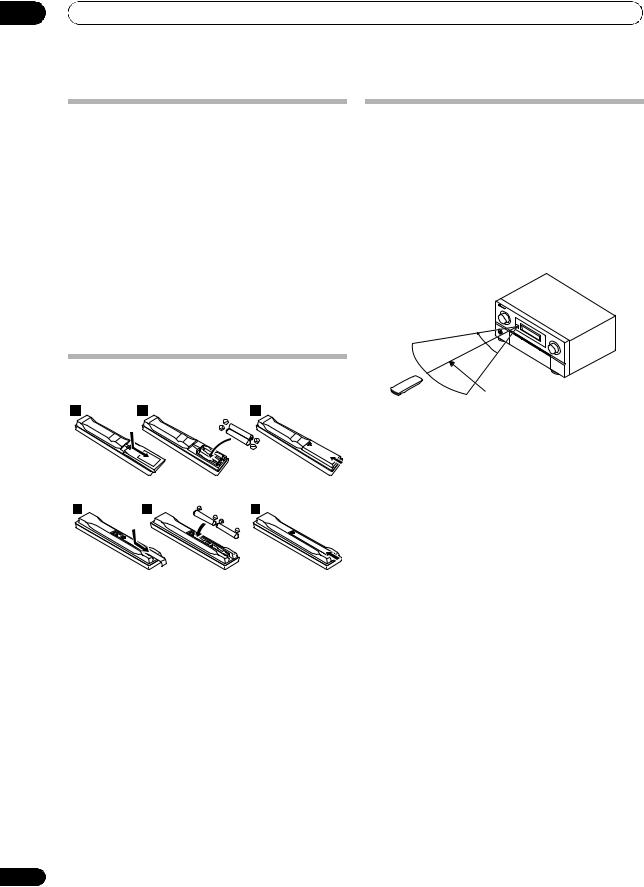
Loading the batteries
In case of SC-LX82
In case of SC-LX72
Operating range of remote control unit
The remote control may not work properly if:
•There are obstacles between the remote control and the receiver’s remote sensor.
•Direct sunlight or fluorescent light is shining onto the remote sensor.
•The receiver is located near a device that is emitting infrared rays.
•The receiver is operated simultaneously with another infrared remote control unit.
30°  30°
30° 
7 m
 CAUTION
Incorrect use of batteries may result in such hazards as leakage and bursting. Observe the following precautions:
•Never use new and old batteries together.
•Insert the plus and minus sides of the batteries properly according to the marks in the battery case.
•Batteries with the same shape may have different voltages. Do not use different batteries together.
•When disposing of used batteries, please comply with governmental regulations or environmental public institution’s rules that apply in your country or area.
•WARNING
Do not use or store batteries in direct sunlight or other excessively hot place, such as inside a car or near a heater. This can cause batteries to leak, overheat, explode or catch fire. It can also reduce the life or performance of batteries.
10
En
Controls and displays |
02 |
Chapter 2:
Controls and displays
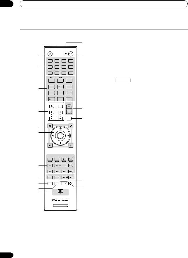
Remote control (In case of SC-LX82)
1
2 |
RECEIVER MAIN |
SOURCE |
||
|
ZONE2 |
3 |
12 |
|
3 |
|
|
MULTI |
|
|
|
OPERATION |
||
|
|
|
||
|
DVD |
BD |
TV |
DVR |
|
|
|
HOME MEDIA |
|
4 |
VIDEO1 |
VIDEO2 |
HDMI |
GALLERY |
USB |
|
CD-R |
|
|
|
iPod |
CD |
TUNER |
|
|
|
MULTICH |
INPUTSELECT |
|
|
PHONO |
IN |
|
|
5 |
|
|
|
13 |
6 |
|
|
|
|
|
|
TV SOURCE RECEIVER |
14 |
|
The remote has been conveniently color-coded according to component control using the following system:
•White – Receiver control, TV Control
•Blue – Other controls
1 MULTI-ZONE operation selector switch
Switch to perform operations in the main zone, ZONE 2 and ZONE 3 (page 88).
2 RECEIVER
This switches between standby and on for this receiver.
3 MULTI OPERATION
Use this button to perform multi operations (page 96).
4 Input function buttons
Press to select control of other components (see
Controlling the rest of your system (In case of SC-LX82) on page 93).
|
CH |
VOL |
|
VOL |
15 |
7 |
|
|
|
||
|
|
|
|
||
|
|
|
|
|
|
|
TVCONTROL |
|
|
16 |
|
|
INPUT |
MUTE |
|
MUTE |
|
|
AUDIO |
|
|
VIDEO |
|
8 |
PARAMETER |
TUNE |
|
PARAMETER |
|
LIST |
|
TOOLS |
|
||
|
|
|
|||
|
|
|
|
|
|
|
TOP MENU |
|
|
T.EDIT |
|
9 |
BAND |
|
|
GUIDE |
|
PRESET |
ENTER |
PRESET |
|
||
|
PTY |
|
|
|
|
|
SEARCH |
|
|
RETURN |
|
|
HOME |
|
|
|
|
|
MENU |
TUNE |
|
|
|
|
iPod CTRL |
|
|
|
|
|
STATUS |
PHASE CTRL |
CH LEVEL |
|
|
|
THX |
MPX |
PQLS |
|
|
10
AUTO/ALC/ |
STEREO |
STANDARD ADV SURR |
|
|
DIRECT |
|
|||
PGM |
MENU |
|
|
|
SIGNAL SEL |
SLEEP |
DIMMER |
AUDIO |
|
A.ATT |
SBch |
MCACC |
INFO |
17 |
11 |
|
|
DISP |
|
|
HDMI OUT |
|
|
|
D.ACCESS |
|
CLASS |
CH |
|
|
|
|
||
ENTER
CLR
5 INPUT SELECT
Use to select the input function (page 49).
6 Character display (LCD)
This display shows information when transmitting control signals.
The following commands are shown when you’re setting the remote to control other components (see Controlling the rest of your system (In case of SC-LX82) on page 93):
SETUP – Indicates the setup mode, from which you choose the options below.
PRESET – See Selecting preset codes directly on page 93.
LEARNING – See Programming signals from other remote controls on page 94.
MULTI OP – See Multi Operation and System Off on page 96.
SYS OFF – See Multi Operation and System Off on page 96.
DIRECT F – See Direct function on page 96.
RENAME – See Renaming input function names on page 95.
ERASE – See Erasing one of the remote control button settings on page 95.
RESET – See Resetting the remote control presets on page 95.
READ ID – See Confirming preset codes on page 95.
11
En

02 Controls and displays
RC MODE – See Operating multiple receivers on page 93.
7 TV CONTROL buttons
These buttons are dedicated to control the TV assigned to the TV operation selector switch. Thus if you only have one TV to hook up to this system assign it to the TV operation selector switch (see page 93 or page 100 for more on this).
– Use to turn on/off the power of the TV.
VOL +/– – Use to adjust the volume on your TV.
INPUT – Use to select the TV input signal.
CH +/– – Use to select channels.
MUTE – Use to mute the sound or cancel the mute mode.
8 Tuner/component control buttons/HOME MENU
These button controls can be accessed after you have selected the corresponding input function button (DVD,
DVR, TV, etc.). The BAND, T.EDIT and PTY SEARCH tuner controls are explained on page 55.
Set the remote control operation selector switch to RECEIVER to access the following controls:
AUDIO PARAMETER – Use to access the Audio options (page 85).
VIDEO PARAMETER – Use to access the Video options (page 87).
HOME MENU – Use to access the Home Menu (pages 44, 47, 82, 106, 115, 118, 120 and 125).
RETURN – Press to confirm and exit the current menu screen (also use to return to the previous menu with DVDs or to select closed captioning with DTV).
9 / / / (TUNE/PRESET) /ENTER
Use the arrow buttons when setting up your surround sound system (see page 106) and the Audio or Video options (page 85 or 87). Also used to control DVD menus/ options and for deck 1 of a double cassette deck player. Use TUNE / to find radio frequencies and use PRESET / to find preset stations (page 55).
10 Component control buttons
The main buttons ( , , etc.) are used to control a component after you have selected it using the input function buttons.
The controls above these buttons can be accessed after you have selected the corresponding input function button (for example DVD, DVR or TV). These buttons also function as described below.
Press TUNER first to access:
MPX – Switches between stereo and mono reception of FM broadcasts. If the signal is weak, then switching to mono will improve the sound quality (page 55). NOISE CUT MODE 1 to 2 can be selected when receiving AM broadcasts.
12
Set the remote control operation selector switch to RECEIVER first to access:
STATUS – Press to check selected receiver settings (page 91).
PHASE CTRL – Press to switch on/off Phase Control or Full Band Phase Control (page 65).
CH LEVEL – Press repeatedly to select a channel, then use / to adjust the level (page 123).
PQLS – Press to select PQLS setting (page 83).
AUTO/ALC/DIRECT – Switches between Auto Surround (page 58), Auto level control, Optimum Surround mode and Stream Direct mode (page 62).
STEREO – Switches between stereo playback and Front Stage Surround Advance modes (page 62).
STANDARD – Press for Standard decoding and to switch between the various 2Pro Logic IIx and Neo:6 options (page 59).
ADV SURR – Use to switch between the various surround modes (page 60).
THX – Press to select a Home THX listening mode (page 60).
11 Number buttons and other receiver/component controls
Use the number buttons to directly select a radio frequency (page 55) or the tracks on a CD, DVD, etc.
ENTER can be used to enter commands for TV or DTV.
After set the remote control operation switch to
RECEIVER:
SIGNAL SEL – Use to select an input signal (page 65).
SLEEP – Use to put the receiver in sleep mode and select the amount of time before sleep (page 90).
DIMMER – Dims or brightens the display (page 90).
A.ATT – Attenuates (lowers) the level of an analog input signal to prevent distortion (page 90).
SBch – Use to select the surround/virtual back channel mode (page 63).
MCACC – Press to switch between MCACC presets (page 64).
HDMI OUT – Switch the HDMI output terminal (page 91).
Press TUNER first to access:
D.ACCESS – After pressing, you can access a radio station directly using the number buttons (page 55).
CLASS – Switches between the seven banks (classes) of radio station presets (page 55).
12 SOURCE
Press to turn on/off other components connected to the receiver (see page 93 for more on this).
En

Controls and displays |
02 |
13 Remote control illumination button
Press to turn on/off the illumination of some of the buttons and the LCD light.1
14 Remote control operation selector switch
Set to RECEIVER to operate the receiver, TV or SOURCE to operate the TV or the source device.
When this switch is set to RECEIVER, the receiver can be controlled (used to select the white commands above the number buttons (A.ATT, etc.)). Also use this switch to set up surround sound.
15 VOL +/–
Use to set the listening volume.
16 MUTE
Mutes the sound or restores the sound if it has been muted (adjusting the volume also restores the sound).
17AUDIO – Changes the audio or channel on DVD or BD discs.
DISP – Switches between named station presets and radio frequencies.
CH +/– – Use to select channels for DVD/DVR units.
 Note
Note
1Press and hold in the remote control illumination button for 5 seconds to change the illumination mode 1 or 2. When set to LIGHT M2 (default), the illumination only lights when the remote control illumination button is pressed. When switched to LIGHT M1, the illumination lights whenever buttons are operated. Setting LIGHT M1 will shorten the service life of the batteries.
13
En
02 Controls and displays
Remote control (In case of SC-LX72)
|
|
|
|
|
|
12 |
|
RECEIVER |
|
|
|
|
SOURCE |
1 |
|
|
|
|
|
13 |
|
DVD |
BD |
DVR |
|
HDMI |
|
2 |
TV |
CD |
CD-R |
HOME MEDIA |
||
|
GALLERY |
|||||
|
|
|
|
|
|
|
|
iPod USB |
TUNER |
VIDEO 1 |
VIDEO 2 |
||
|
|
INPUT |
HDMI OUT |
|||
|
SELECT |
|||||
|
1 |
|
|
2 |
|
3 |
|
SIGNAL SEL |
MCACC |
SLEEP |
|||
3 |
4 |
|
|
5 |
|
6 |
SBch |
|
A.ATT |
DIMMER |
|||
|
7 |
|
|
8 |
|
9 |
|
D.ACCESS |
CH LEVEL |
CLASS |
|||
|
/CLR |
|
|
0 |
ENTER |
|
|
|
|
INPUT |
MASTER |
||
|
|
|
VOLUME |
|||
4 |
TV CONTROL |
|
14 |
|||
|
|
|
|
|
|
|
|
CH |
|
VOL |
|
MUTE |
|
|
|
|
|
|
|
15 |
|
AUDIO |
|
|
|
|
VIDEO |
5 |
PARAMETER |
|
|
|
|
PARAMETER |
LIST |
TUNE TOOLS |
|||||
TOP MENU |
|
|
|
|
T.EDIT |
|
|
|
|
|
|
||
6 |
BAND |
|
|
|
|
GUIDE |
PRESET |
|
ENTER |
|
PRESET |
||
|
|
|
||||
|
PTY |
|
|
|
|
|
|
SEARCH |
|
|
|
|
RETURN |
|
HOME |
TUNE |
|
|
||
|
MENU |
|
|
|||
|
iPod CTRL |
|
|
|
|
|
|
AUTO/ALC/ |
STEREO |
STANDARD |
MENU |
||
|
DIRECT |
ADV SURR |
||||
|
PGM HDD |
DVD |
|
|
|
|
7 |
THX |
PHASE CTRL |
|
STATUS |
||
TV/DTV |
MPX |
PQLS |
|
|
||
|
|
|
||||
8 |
AUDIO |
INFO |
|
CH |
||
|
DISP |
|
|
16 |
||
9 |
MULTI OPE |
TV CTRL |
RECEIVER |
|||
REMOTE |
|
|
|
|
17 |
|
10 |
|
|
|
|
||
SETUP |
|
|
|
|
|
|
|
|
|
|
|
|
|
11 |
|
|
MAIN |
|
|
|
|
ZONE 2 |
ZONE 3 |
||||
RECEIVER
The remote has been conveniently color-coded according to component control using the following system:
•White – Receiver control, TV Control
•Blue – Other controls
1 RECEIVER
This switches between standby and on for this receiver.
2 Input function buttons
Press to select control of other components (see
Controlling the rest of your system (In case of SC-LX72) on page 100).
3 Number buttons and other receiver/component controls
Use the number buttons to directly select a radio frequency (page 55) or the tracks on a CD, DVD, etc.
ENTER can be used to enter commands for TV or DTV.
Press RECEIVER first to access:
INPUT SELECT – Use to select the input function (page 49).
HDMI OUT – Switch the HDMI output terminal (page 91).
SIGNAL SEL – Use to select an input signal (page 65).
MCACC – Press to switch between MCACC presets (page 64).
SLEEP – Use to put the receiver in sleep mode and select the amount of time before sleep (page 90).
SBch – Use to select the surround back/virtual surround back channel mode (page 63).
A.ATT – Attenuates (lowers) the level of an analog input signal to prevent distortion (page 90).
DIMMER – Dims or brightens the display (page 90).
CH LEVEL – Press repeatedly to select a channel, then use / to adjust the level (page 123).
Press TUNER first to access:
D.ACCESS – After pressing, you can access a radio station directly using the number buttons (page 55).
CLASS – Switches between the seven banks (classes) of radio station presets (page 55).
4 TV CONTROL buttons
These buttons are dedicated to control the TV assigned to the TV operation selector switch. Thus if you only have one TV to hook up to this system assign it to the TV operation selector switch (see page 103 for more on this).
– Use to turn on/off the power of the TV.
INPUT – Use to select the TV input signal.
CH +/– – Use to select channels.
VOL +/– – Use to adjust the volume on your TV.
5 Tuner/component control buttons/HOME MENU
These button controls can be accessed after you have selected the corresponding input function button (DVD,
DVR, TV, etc.). The BAND, T.EDIT and PTY SEARCH tuner controls are explained on page 55 and page 56.
14
En
Controls and displays |
02 |
Press RECEIVER first to access:
AUDIO PARAMETER – Use to access the Audio options (page 85).
VIDEO PARAMETER – Use to access the Video options (page 87).
HOME MENU – Use to access the Home Menu (pages 44, 47, 82, 106, 115, 118, 120 and 125).
RETURN – Press to confirm and exit the current menu screen (also use to return to the previous menu with DVDs or to select closed captioning with DTV).
6 / / / (TUNE/PRESET) /ENTER
Use the arrow buttons when setting up your surround sound system (see page 106) and the Audio or Video options (page 85 or 87). Also used to control DVD menus/ options and for deck 1 of a double cassette deck player. Use TUNE/to find radio frequencies and use PRESET / to find preset stations (page 55).
7 Component/Receiver control buttons
The main buttons ( , , etc.) are used to control a component after you have selected it using the input function buttons.
The controls above these buttons can be accessed after you have selected the corresponding input function button (for example DVD, DVR or TV). These buttons also function as described below.
Press TUNER first to access:
MPX – Switches between stereo and mono reception of FM broadcasts. If the signal is weak, then switching to mono will improve the sound quality (page 55).
NOISE CUT MODE 1 or 2 can be selected when this unit is receiving AM broadcasts.
Press RECEIVER first to access:
AUTO/ALC/DIRECT – Switches between Auto Surround (page 58), Auto level control, Optimum Surround mode and Stream Direct mode (page 62).
STEREO – Switches between stereo playback and Front Stage Surround Advance modes (page 62).
STANDARD – Press for Standard decoding and to switch between the various 2Pro Logic IIx and Neo:6 options (page 59).
ADV SURR – Use to switch between the various surround modes (page 60).
THX – Press to select a Home THX listening mode (page 60).
PHASE CTRL – Press to switch on/off Phase Control or Full Band Phase Control (page 65).
STATUS – Press to check selected receiver settings (page 91).
PQLS – Press to select PQLS setting (page 83).
8AUDIO – Changes the audio or channel on DVD or BD discs.
DISP – Switches between named station presets and radio frequencies.
CH +/– – Use to select channels for DVD/DVR units.
9REMOTE SETUP
Use to input the preset code when making remote control settings and to set the remote control mode (page 100).
10 TV CTRL
Use this button to set preset code of your TV’s manufacturer when controlling TV (see Selecting preset codes directly on page 100 for more on this).
11 MULTI-ZONE operation selector switch
Switch to perform operations in the main zone, ZONE 2 and ZONE 3 (page 89).
12 Remote control LED
Lights when a command is sent from the remote control (page 100).
13 SOURCE
Press to turn on/off other components connected to the receiver (see page 100 for more on this).
14MASTER VOLUME +/–
Use to set the listening volume.
15MUTE
Mutes the sound or restores the sound if it has been muted (adjusting the volume also restores the sound).
16 RECEIVER
Switches the remote to control the receiver (used to select the white commands above the number buttons (A.ATT, etc.)). Also use this button to set up surround sound.
17
Press to turn on/off the illumination of some of the buttons.
15
En
02 Controls and displays
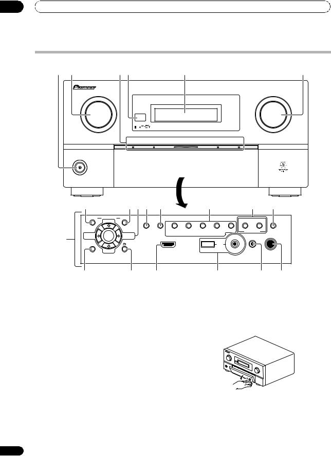
Front panel
1 |
2 |
3 |
4 |
5 |
6 |
INPUT |
|
|
MASTER |
SELECTOR |
|
|
VOLUME |
PHASE |
ADVANCED |
|
|
CONTROL |
MCACC |
PQLS |
HDMI |
STANDBY/ON
|
8 |
|
9 10 11 |
12 |
13 |
14 |
15 |
|
|
AUDIO |
PARAMETER |
VIDEO |
|
|
|
|
|
|
|
(TUNE) |
|
|
|
|
CONTROL ON/OFF |
|
|
|
|
TUNER EDIT |
BAND AUTO SURR/ALC/ HOME |
STANDARD |
ADVANCED STEREO |
MULTI-ZONE |
SPEAKERS |
7 |
(PRESET) |
ENTER |
(PRESET) |
STREAM DIRECT THX |
SURROUND |
SURROUND |
|
|
|
|
|
|
|
||||
|
|
|
|
|
iPod |
|
|
|
|
|
|
|
|
|
|
|
|
|
|
|
|
|
|
iPhone |
|
|
|
|
(TUNE) |
|
HDMI 4 |
USB |
|
MCACC |
|
|
HOME MENU |
|
RETURN |
VIDEO CAMERA |
|
|
SETUP MIC |
PHONES |
16 |
17 |
18 |
1 STANDBY/ON
Switches the receiver between on and standby. Power indicator lights when the receiver is on.
When the KURO LINK function is set to ON, the power indicator lights when the power is in standby.
2 INPUT SELECTOR dial
Use to select an input function (page 49).
3PHASE CONTROL indicator – Lights to indicate Phase Control or Full Band Phase Control is selected (page 65).
ADVANCED MCACC indicator – Lights when EQ is set to ON in the AUDIO PARAMETER menu
(page 85).
PQLS indicator – Lights when the PQLS feature is active (page 83).
HDMI indicator – Blinks when connecting an HDMIequipped component; lights when the component is connected (page 28).
4Remote sensor
Receives the signals from the remote control (see
Operating range of remote control unit on page 10).
19 |
20 |
21 |
5Character display
See Display on page 17.
6MASTER VOLUME dial
7Front panel controls
To access the front panel controls, push gently on the lower third portion of the panel with your finger.
8 AUDIO PARAMETER
Use to access the Audio options (page 85).
9 VIDEO PARAMETER
Use to access the Video options (page 87).
16
En
Controls and displays |
02 |
10 / / / (TUNE/PRESET) /ENTER
Use the arrow buttons when setting up your HOME MENU. Use TUNE /to find radio frequencies and use PRESET / to find preset stations (page 55).
11 TUNER EDIT
Use with / / //ENTER to memorize and name stations for recall (page 55).
12 BAND
Switches between AM and FM radio bands (page 55).
13Listening mode buttons
AUTO SURR/ALC/STREAM DIRECT – Switches between Auto Surround (page 58), Auto level control, Optimum Surround mode and Stream Direct mode (page 62).
HOME THX – Press to select a Home THX listening mode (page 60).
STANDARD SURROUND – Press for Standard decoding and to switch between the various 2Pro Logic IIx and Neo:6 options (page 59).
ADVANCED SURROUND – Use to switch between the various surround modes (page 60).
STEREO – Switches between stereo playback and Front Stage Surround Advance modes (page 62).
14 MULTI-ZONE controls
If you’ve made MULTI-ZONE connections (see MULTIZONE setup on page 37) use these controls to control the sub zone from the main zone (see Using the MULTI-ZONE controls on page 88).
15 SPEAKERS
Use to change the speaker system (page 88).
16 HOME MENU
Press to access the Home Menu (pages 44, 47, 82, 106, 115, 118, 120 and 125).
17 RETURN
Press to confirm and exit the current menu screen.
18 HDMI input connector
Use for connection to compatible HDMI device (Video camera, etc.). See Connecting an HDMI-equipped component to the front panel input on page 41.
19 iPod/iPhone/USB terminals
Use to connect your Apple iPod as an audio and video source, or connect a USB device for audio and photo playback (page 42).
20 MCACC SETUP MIC jack
Use to connect the supplied microphone (page 45).
21 PHONES jack
Use to connect headphones. When the headphones are connected, there is no sound output from the speakers.
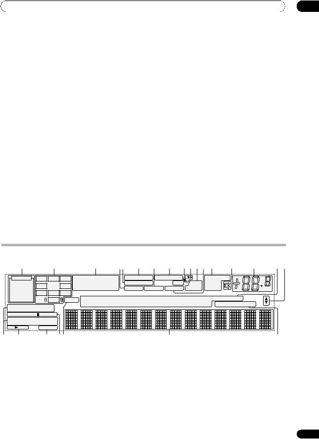
Display |
|
|
|
|
|
|
|
|
|
|
|
|
|
|
|
|
|
|
1 |
|
2 |
|
|
3 |
45 |
6 |
7 |
8 |
9 10 1112 13 |
|
14 |
15 |
16 17 |
||
AUTO |
|
|
|
2 |
|
|
DSD PCM FULL BAND |
|
TUNED RDS |
|
|
||||||
L |
C |
R |
DIGITAL PLUS |
|
|
|
|||||||||||
|
PCM |
2 |
|
|
MULTI-ZONE PQLS |
ALC |
ATT |
STEREO |
|
|
|
||||||
|
SL |
|
SR |
TrueHD WMA9Pro |
|
|
|
||||||||||
HDMI |
XC |
DTS HD ES 96/24 |
S.RTRV SOUND UP MIX OVER |
MONO |
|
|
dB |
||||||||||
DIGITAL |
XL |
XR |
|
|
|
|
|
|
|
|
|
|
|
|
|
||
ANALOG |
|
LFE |
MSTR |
CD |
TUNER |
iPod |
DVD |
TV |
VIDEO HMG USB |
[ 4 ] |
|
||||||
AUTO SURROUND |
|
|
CD-R |
PHONO |
BD |
DVR |
HDMI |
[ 2 ] |
[ 3 ] |
|
|||||||
STREAM DIRECT |
|
|
|
|
|
|
|
|
|
|
|
|
|
|
|||
2PROLOGIC |
x Neo:6 |
|
|
|
|
|
|
|
|
|
|
|
|
|
|
||
THX ADV.SURROUND |
|
|
|
|
|
|
|
|
|
|
|
|
|
|
|||
STEREO STANDARD |
|
|
|
|
|
|
|
|
|
|
|
|
|
|
|||
SP |
AB |
SLEEP |
|
|
|
|
|
|
|
|
|
|
|
|
|
|
|
9 |
18 |
19 |
20 21 |
|
|
|
|
|
22 |
|
|
|
|
|
|
23 |
|
1 SIGNAL indicators
Light to indicate the currently selected input signal. AUTO lights when the receiver is set to select the input signal automatically (page 65).
2 Program format indicators
Light to indicate the channels being input when PCM signals are being input. They do not indicate the audio signals being output from the receiver.
L/R – Left front/Right front channel
C – Center channel
SL/SR – Left surround/Right surround channel
LFE – Low frequency effects channel (the (( )) indicators light when an LFE signal is being input)
XL/XR – Two channels other than the ones above
XC – Either one channel other than the ones above, the mono surround channel or matrix encode flag
3 Digital format indicators
Light when a signal encoded in the corresponding format is detected.
4 S.RTRV
Lights when the Sound Retriever function is active (page 85).
17
En

02 Controls and displays
5 MULTI-ZONE
Lights when the MULTI-ZONE feature is active (page 88).
6DSD PCM – Light during DSD (Direct Stream Digital) to PCM conversion with SACDs.
PCM – Lights during playback of PCM signals.
7SOUND
Lights when any of the Midnight, Loudness or tone controls feature is selected (page 85).
Lights when Dialog Enhancement is switched on.
8 FULL BAND
Lights when the Full Band Phase Control is switched on (page 66).
9Listening mode indicators
AUTO SURROUND – Lights when the Auto Surround feature is switched on (page 58).
ALC – Lights when the ALC (Auto level control) mode is selected (page 62).
STREAM DIRECT – Lights when Direct/Pure Direct is selected (page 62).
ADV.SURROUND – Lights when one of the Advanced Surround modes has been selected (page 60).
STEREO – Lights when stereo listening is switched on (page 61).
STANDARD – Lights when one of the Standard Surround modes is switched on (page 59).
THX – Lights when one of the Home THX modes is selected (page 60).
10 (PHASE CONTROL)
Lights when the Phase Control or Full Band Phase Control is switched on (page 65).
11 Analog signal indicators
Light to indicate reducing the level of an analog signal (page 90).
12 UP MIX
Lights when the Up Mix is switched on (page 64).
13Tuner indicators
TUNED – Lights when a broadcast is being received. STEREO – Lights when a stereo FM broadcast is being received in auto stereo mode.
MONO – Lights when the mono mode is set using
MPX.
RDS – Lights when an RDS broadcast is received.
14
Lights when the sound is muted (page 15).
15 Master volume level
Shows the overall volume level.
“---” indicates the minimum level, and “+12dB” indicates the maximum level.
18
16 Input function indicators
Light to indicate the input function you have selected.
17 Scroll indicators
Light when there are more selectable items when making the various settings.
18 Speaker indicators
Lights to indicate the current speaker system, A and/or B (page 88).
19 SLEEP
Lights when the receiver is in sleep mode (page 90).
20Matrix decoding format indicators
2PRO LOGIC IIx – This lights to indicate 2Pro Logic II / 2Pro Logic IIx decoding (page 59).
Neo:6 – When one of the Neo:6 modes of the receiver is on, this lights to indicate Neo:6 processing (page 59).
21MSTR
Lights during playback of DTS-HD Master Audio signal.
22 Character display
Displays various system information.
23 Remote control mode indicator
Lights to indicate the receiver’s remote control mode setting. (Not displayed when set to 1.) (SC-LX82: page 93,
SC-LX72: page 100)
En
Connecting your equipment |
03 |
Chapter 3:
Connecting your equipment
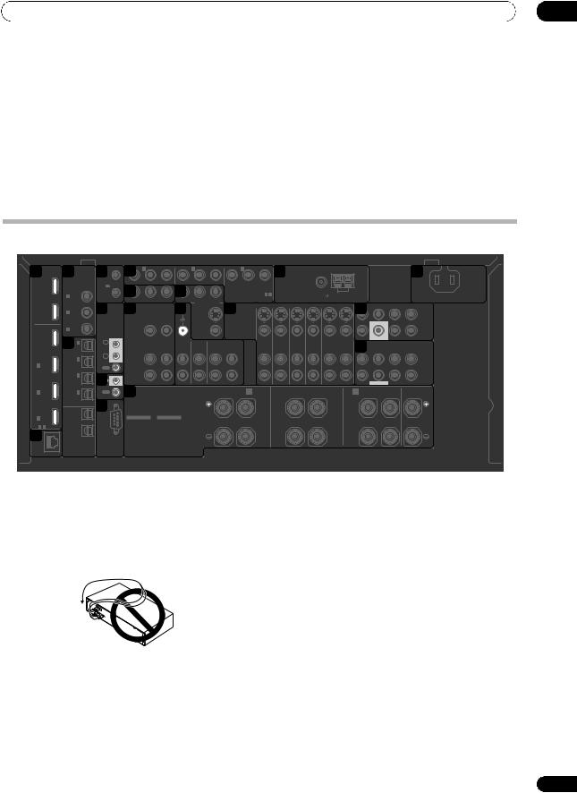
This receiver provides you with many connection possibilities, but it doesn’t have to be difficult. This page explains the kinds of components you can connect to make up your home theater system.
 Important
• Illustration shows the SC-LX82, however connections for the SC-LX72 are the same except where noted.
Rear panel
1 HDMI |
3 |
|
12V |
1 |
9 |
IN 1 |
|
IN 2 |
|
|
|
IN 3 |
|
15 |
|
|
|
|
|
|
|
|
19 |
|
|
|
TRIGGER5 |
|
|
|
|
|
|
|
|
|
|
|
|
|
|
|
|
|
|
AC IN |
|||||
|
COAXIAL |
(OUTPUT |
|
|
|
|
|
|
|
|
|
|
|
|
|
|
|
|
|
|
|
|
|
|
|
OUT |
ASSIGNABLE |
|
(DVD) |
|
|
(DVR) |
|
|
|
PR |
PB |
Y |
ANTENNA |
|
|
|
|
|
|
|
|
|
|||
|
|
12V |
|
|
|
|
|
|
|
|
|
|
|
|
|
|
|
|
|||||||
1 |
|
|
|
10PR |
|
|
12 |
|
|
|
(VIDEO 1) |
|
|
|
|
|
|
|
|
|
|
|
|
||
|
|
TOTAL |
|
|
|
|
|
|
|
|
|
|
|
|
|
|
|
|
|
|
|||||
(KURO |
|
|
|
|
|
|
|
|
|
|
|
|
|
|
|
|
|
|
|
|
|
|
|||
|
|
50 mA |
|
|
|
|
|
|
|
ASSIGNABLE 1 - 3 |
|
|
FM UNBAL 75 |
AM LOOP |
|
|
|
|
|
|
|||||
LINK ) |
IN 1 (DVD) |
|
PB |
Y |
|
|
|
|
|
|
|
|
|
|
|
|
|||||||||
|
|
|
MAX) |
2 |
|
ZONE 2 OUT |
PR |
PB |
Y |
|
|
COMPONENT VIDEO |
|
|
|
|
|
|
|
|
|
|
|
||
2 |
IN 2 (CD) |
6 |
|
11 |
|
|
13 |
|
MONITOR OUT |
14 S-VIDEO |
|
|
|
|
|
|
16 |
CENTER |
|
L |
|
||||
|
|
|
|
|
|
|
|
SIGNAL |
|
|
|
|
|
|
|
|
|
|
|
|
FRONT |
SURROUND SURROUNDBACK |
|
||
OUT |
|
|
|
|
|
|
|
|
|
|
|
|
|
|
|
|
|
|
|
|
|
|
(Single) |
|
|
|
|
|
|
|
|
|
GND |
|
|
|
|
|
|
|
|
|
|
|
|
|
|
|
|
||
|
|
|
|
|
|
|
|
|
|
|
|
|
|
|
|
|
|
|
|
|
|
|
|
|
|
|
|
|
|
|
|
|
|
|
|
|
|
|
|
|
|
|
|
|
|
|
|
|
|
PRE OUT |
|
|
IN 3 |
|
IR |
|
VIDEO |
|
|
|
|
|
|
VIDEO |
|
|
|
|
|
|
|
|
|
|
R |
|
|
BD |
(VIDEO 2) |
|
|
|
|
|
|
|
|
|
|
|
|
|
|
|
|
|
|
|
SUBWOOFER |
|
|
|
|
IN |
4 |
|
IN |
|
|
|
|
|
|
|
|
|
|
|
|
|
|
|
|
17FRONT |
|
|
|
||
|
IN 1 |
|
|
ZONE 2 |
ZONE 3 |
PHONO |
|
CD |
CD-R/TAPE |
|
DVD |
TV/SAT |
VIDEO1 |
VIDEO2 |
OUT |
DVR |
|
|
MULTI CH IN |
|
|||||
|
(TV/SAT) |
1 |
|
|
OUT |
OUT |
IN |
|
IN |
OUT |
IN |
|
IN |
IN |
IN |
IN |
IN |
CENTER |
SURROUND SURROUNDBACK |
|
|||||
|
|
|
|
|
|
|
|
|
|
|
|
|
|
|
|
|
|
|
|
|
|||||
|
|
IN 2 |
IN |
|
|
L |
|
|
|
|
|
|
|
|
|
|
|
|
|
|
|
|
|
L |
|
IN |
|
2 |
|
|
|
|
|
|
|
|
|
|
|
|
|
|
|
|
|
|
|
|
|||
(DVR) |
|
|
|
|
|
|
|
|
|
|
|
|
|
|
|
|
|
|
|
|
|
|
|
||
1 |
|
|
|
|
|
|
|
|
|
|
|
|
|
|
|
|
|
|
|
|
|
|
|
||
|
|
OUT |
|
|
|
|
|
|
|
|
|
|
|
|
|
|
|
|
|
|
|
|
|
|
|
|
|
|
|
|
|
|
|
|
|
|
|
|
|
|
|
|
|
|
|
|
|
|
|
|
|
|
|
IN 3 |
7IN |
|
|
R |
|
|
|
|
|
|
|
|
|
|
|
|
|
|
|
|
|
R |
|
|
(VIDEO1) |
|
|
|
|
|
|
|
|
|
|
|
|
|
|
|
|
|
|
SUBWOOFER |
|
|
|||
|
|
|
|
|
|
|
|
|
|
|
|
|
|
|
|
|
|
|
|
|
|
||||
IN |
|
|
CONTROL |
|
SPEAKERS |
|
|
|
|
R SURROUND BACK/ B |
|
|
|
|
|
|
A |
|
|
|
|
|
|||
2 |
|
IN 4 |
OUT |
|
18 |
|
|
|
|
|
L (Single) |
R |
SURROUND |
L |
|
R |
FRONT |
L |
CENTER |
|
|||||
|
(CD-R) |
8 |
|
|
CAUTION: |
|
|
|
|
|
|
|
|
|
|
|
|
|
|
|
|
|
|||
|
ASSIGNABLE |
|
|
|
|
|
|
|
|
|
|
|
|
|
|
|
|
|
|
|
|
||||
|
|
|
|
SPEAKER IMPEDANCE 6 Ω- 16 Ω. |
|
|
|
|
|
|
|
|
|
|
|
|
|
|
|
||||||
|
|
|
|
|
|
ATTENTION: |
|
|
|
|
|
|
|
|
|
|
|
|
|
|
|
|
|
||
IN |
OUT 1 |
|
|
|
|
ENCEINTE D'IMPEDANCE DE 6 Ω- 16 Ω. |
|
|
|
|
|
|
|
|
|
|
|
|
|
|
|
||||
3 |
|
|
|
|
SELECTABLE |
SELECTABLE |
|
|
|
|
|
|
|
|
|
|
|
|
|
|
|
|
|
||
ASSIGNABLE |
|
|
|
|
SEE INSTRUCTION |
VOIR LE MODE |
|
|
|
|
|
|
|
|
|
|
|
|
|
|
|
|
|
||
1 - 3 |
|
|
|
|
MANUAL |
D'EMPLOI |
|
|
|
|
|
|
|
|
|
|
|
|
|
|
|
|
|
|
|
2LAN |
OUT 2 |
RS-232C |
|
|
|
|
|
|
|
|
|
|
|
|
|
|
|
|
|
|
|
|
|
|
|
OPTICAL |
|
|
|
|
|
|
|
|
|
|
|
|
|
|
|
|
|
|
|
|
|
|
|||
(10/100) |
|
|
|
|
|
|
|
|
|
|
|
|
|
|
|
|
|
|
|
|
|
|
|
||
 CAUTION
•Before making or changing the connections, switch off the power and disconnect the power cord from the power outlet. Plugging in should be the final step.
•To avoid hum, do not lay connected cables over the top of the receiver.
1 HDMI connectors (x6)
Multiple inputs and two outputs for high-quality audio/ video connection to compatible HDMI devices.
See Connecting your TV and playback components on page 28.
See Switching the HDMI output on page 91.
2LAN (10/100) terminal
See Playback with HOME MEDIA GALLERY inputs on page 68.
3Coaxial digital audio inputs (x3 (SC-LX82), x2 (SCLX72))
Use for digital audio sources, including DVD players/ recorders, digital satellite receivers, CD players, etc.
See also The Input Setup menu on page 47 to assign the inputs.
4Optical digital audio inputs (x4)/outputs (x2)
Use the OUT jack for recording to a CD or MiniDisc recorder.
See Connecting other audio components on page 34.
Use the IN jacks for digital audio sources, including DVD players/recorders, digital satellite receivers, CD players, etc.
See also The Input Setup menu on page 47 to assign the inputs.
5 12 V trigger jacks (total 50 mA max.) (x2)
Use to switch components in your system on and off according to the input function of the receiver.
See Switching components on and off using the 12 volt trigger on page 40.
19
En

03 Connecting your equipment
6 |
Remote inputs/output |
17 Multichannel analog audio inputs |
Use for connection to an external remote control sensor |
7.1 channel inputs for connection to a DVD player with |
|
for use in a MULTI-ZONE setup, for example. |
multichannel analog outputs. |
|
See Connecting an IR receiver on page 39. |
See Connecting the multichannel analog inputs on |
|
7 |
Control input/output |
page 33. |
|
||
Use to connect other Pioneer components so that you |
18 Speaker terminals |
|
can control all your equipment from a single IR remote |
Use for connection to the main front, center, surround |
|
sensor. |
and surround back speakers. |
|
See Operating other Pioneer components with this |
See Connecting the speakers on page 23. |
|
unit’s sensor on page 39.
19 AC power inlet
8 RS-232C connector
Use for connection to a PC for graphical output when using Advanced MCACC or Full Band Phase Control.
See Connecting a PC for Advanced MCACC output on page 40.
9 Component video inputs (x3)
Use the inputs to connect any video source that has component video output, such as a DVD player.
See Connecting your DVD player with no HDMI output on page 29.
10SC-LX82 only: ZONE 2 component video output
Use to connect monitors or TVs in a separate room.
See MULTI-ZONE setup on page 37.
11MULTI-ZONE audio/video outputs
Use to connect a second or third amplifier and monitors or TVs in a separate room.
See MULTI-ZONE setup on page 37.
12Composite, S-Video and Component video monitor outputs
Use to connect monitors and TVs.
See Connecting your TV with no HDMI input on page 30.
13Stereo analog audio source inputs (x3)/output (x1)
Use for connection to audio sources such as CD players, tape decks, turntables, etc.
See Connecting other audio components on page 34.
14Audio/video source inputs (x5)/output (x1)
Use for connection to audio/visual sources, such as DVD players/recorders, VCRs, etc. Each set of inputs has jacks for composite video, S-Video and stereo analog audio.
See Connecting an HDD/DVD recorder, VCR and other video sources on page 32.
15 AM and FM antenna terminals
Use to connect indoor or outdoor antennas for radio broadcasts.
See Connecting AM/FM antennas on page 35.
16 Multichannel pre-amplifier outputs
Use to connect separate amplifiers for front, center, surround, surround back and subwoofer channels.
See Connecting additional amplifiers on page 35 (see also Installing your speaker system on page 24 for powered subwoofer connection).
Connect the supplied power cord here.
See Plugging in the receiver on page 43.
20
En
Connecting your equipment
Determining the speakers’ application
Surround sound with a strong sense of presence can be enjoyed by connecting 7 speakers and 1 subwoofer. It is also possible to achieve high sound quality using bi-amp connections and to enjoy music in other rooms using the MULTI-ZONE feature. High sound quality can be achieved with a minimum of two speakers.
•Be sure to connect speakers to the front left and right channels ( L and R ).
•The Surr Back System setting must be made if you use any of the connections shown below other than [1] (see Selecting the Surr Back system on page 26).
[1] 7.1ch surround connection (Simple connection & Best surround)
*Default setting
These connections prioritize surround sound with a speaker layout like that in a movie theater.
•Surr Back System setting: Normal (default)
•If you have six speakers, either only connect one surround back speaker (6.1 ch surround), or connect for the 7.1-channel setting as shown on the diagram below but without the center speaker.
L |
SW |
C |
R |
Front |
|
Front |
|
left |
|
Center |
right |
Subwoofer |
|
|
|
SL |
|
|
SR |
Surround |
Surround |
||
left |
|
|
right |
|
SBL |
SBR |
|
|
Surround |
Surround |
|
|
back left |
back right |
|
[2] 5.1ch surround & Front Bi-amping connection (High quality surround)
Bi-amping connection of the front speakers for high sound quality with 5.1-channel surround sound.
• Surr Back System setting: Front Bi-Amp
L |
SW |
R |
Front |
C |
Front |
left* |
Center |
right* |
Subwoofer |
|
|
Surround |
|
Surround |
left |
|
right |
SL |
|
SR |
*Bi-amp compatible speaker
03
[3] 5.1ch surround & ZONE 2 connection (Multi Zone)
With these connections you can simultaneously enjoy 5.1-channel surround sound in the main zone with stereo playback on another component in ZONE 2. (The selection of input devices is limited.)
• Surr Back System setting: ZONE 2
L |
SW |
R |
L |
R |
Front |
C |
Front |
||
left |
Center |
right |
Left |
Right |
Subwoofer |
|
|
ZONE 2 |
|
|
|
|
|
|
Surround |
|
Surround |
|
|
left |
|
right |
|
|
SL |
|
SR |
|
|
[4] 5.1ch surround & Speaker B connection
With these connections you can simultaneously enjoy 5.1-channel surround sound in the main zone with stereo playback of the same sound on the B speakers.
• Surr Back System setting: Speaker B
L |
SW |
R |
Speaker B |
Front |
C |
Front |
|
left |
Center |
right |
|
Subwoofer |
|
|
|
Surround |
|
Surround |
|
left |
|
right |
|
SL |
|
SR |
|
Other speaker connection
•Your favorite speaker connections can be selected even if you have fewer than 5.1 speakers.
•When not connecting a subwoofer, connect speakers with low frequency reproduction capabilities to the front channel. (The subwoofer’s low frequency component is played from the front speakers, so the speakers could be damaged.)
•After connecting, be sure to conduct the Auto MCACC (speaker environment setting) procedure.
See Automatically setting up for surround sound (Auto MCACC & Full Band Phase Control) on page 45.
21
En
03 Connecting your equipment
Placing the speakers
To achieve the best possible surround sound, install your speakers as shown below.
5.1 channel surround system:
Center |
Front right |
Front left |
|
Subwoofer |
|
120° |
120° |
Surround |
Surround |
left |
right |
6.1 channel surround system:
Center |
Front right |
Front left |
|
Subwoofer |
|
120° |
120° |
Surround |
Surround |
left |
right |
Surround Back
7.1 channel surround system:
Front left |
Center |
Front right |
|
||
Subwoofer |
|
|
90° |
|
90° |
Surround |
|
Surround |
left |
|
right |
Surround back |
60° |
Surround back |
left |
|
right |
THX speaker system setup
If you are using a THX certified subwoofer use the THX INPUT jack on the subwoofer (if your subwoofer has one) or switch the filter position to THX on your subwoofer.
See also THX Audio Setting on page 124 to make the settings that will give you the best sound experience when using the Home THX modes (page 60).
Some tips for improving sound quality
Where you put your speakers in the room has a big effect on the quality of the sound. The following guidelines should help you to get the best sound from your system.
•The subwoofer can be placed on the floor. Ideally, the other speakers should be at about ear-level when you’re listening to them. Putting the speakers on the floor (except the subwoofer), or mounting them very high on a wall is not recommended.
•For the best stereo effect, place the front speakers 2 m to 3 m apart, at equal distance from the TV.
•If you’re using a center speaker, place the front speakers at a wider angle. If not, place them at a narrower angle.
•Place the center speaker above or below the TV so that the sound of the center channel is localized at the TV screen. Also, make sure the center speaker does not cross the line formed by the leading edge of the front left and right speakers.
•It is best to angle the speakers towards the listening position. The angle depends on the size of the room. Use less of an angle for bigger rooms.
•Surround and surround back speakers should be positioned 60 cm to 90 cm higher than your ears and tilted slight downward. Make sure the speakers don’t face each other. For DVD-Audio, the speakers should be more directly behind the listener than for home theater playback.
•If the surround speakers cannot be set directly to the side of the listening position with a 7.1-channel system, the surround effect can be enhanced by turning off the Up Mix function (see Setting the Up Mix function on page 64).
•Try not to place the surround speakers farther away from the listening position than the front and center speakers. Doing so can weaken the surround sound effect.
22
En
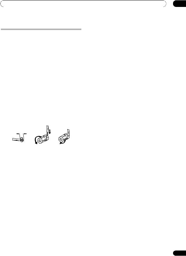
Connecting your equipment |
03 |
Connecting the speakers
Each speaker connection on the receiver comprises a positive (+) and negative (–) terminal. Make sure to match these up with the terminals on the speakers themselves.
 CAUTION
•These speaker terminals carry HAZARDOUS LIVE voltage. To prevent the risk of electric shock when connecting or disconnecting the speaker cables, disconnect the power cord before touching any uninsulated parts.
•Make sure that all the bare speaker wire is twisted together and inserted fully into the speaker terminal. If any of the bare speaker wire touches the back panel it may cause the power to cut off as a safety measure.
Bare wire connections
1Twist exposed wire strands together. (fig. A)
2Loosen terminal and insert exposed wire. (fig. B)
3Tighten terminal. (fig. C)
fig. A |
fig. B |
fig. C |
10 mm
 Important
•Please refer to the manual that came with your speakers for details on how to connect the other end of the speaker cables to your speakers.
•Use an RCA cable to connect the subwoofer. It is not possible to connect using speaker cables.
 CAUTION
•Make sure that all speakers are securely installed. This not only improves sound quality, but also reduces the risk of damage or injury resulting from speakers being knocked over or falling in the event of external shocks such as earthquakes.
23
En

03 Connecting your equipment
Installing your speaker system
At the very least, front left and right speakers only are necessary. Note that your main surround speakers should always be connected as a pair, but you can connect just one surround back speaker if you like (it must be connected to the left surround back terminal).
Standard 5.1/6.1/7.1-channel surround connections
Subwoofer Center
Front left |
Front right |
|
|
|
|
|
|
|
LINE LEVEL |
|
|
|
|
|
|
|
|
|
|
|
|
|
|
|
|
|
|
|
|
|
|
INPUT |
|
|
|
|
|
|
|
|
|
|
|
|
|
|
|
HDMI |
|
12V |
1 |
|
IN 1 |
|
IN 2 |
|
|
|
IN 3 |
|
|
|
|
|
|
|
|
|
AC IN |
|
COAXIAL |
TRIGGER |
|
|
|
|
|
|
|
|
|
|
|
|
|
|
|
|
|
|
|
||
|
|
|
|
|
|
|
|
|
|
|
|
|
|
|
|
|
|
|
|
|
|
|
OUT |
ASSIGNABLE |
(OUTPUT |
|
(DVD) |
|
(DVR) |
|
|
|
PR |
PB |
Y |
ANTENNA |
|
|
|
|
|
|
|
||
|
12V |
|
|
|
|
|
|
|
|
|
|
|
|
|
|
|||||||
1 |
|
|
|
|
|
|
|
|
|
(VIDEO 1) |
|
|
|
|
|
|
|
|
|
|
||
|
TOTAL |
|
|
|
|
|
|
|
|
|
|
|
|
|
|
|
|
|
|
|||
(KURO |
|
|
|
|
|
|
|
|
|
|
ASSIGNABLE 1 - 3 |
|
|
|
|
|
|
|
|
|
||
IN 1 (DVD) |
50 mA |
|
|
|
|
|
|
|
|
|
|
|
FM UNBAL 75 |
AM LOOP |
|
|
|
|
||||
LINK ) |
|
PR |
PB |
Y |
|
|
|
|
|
|
|
|
|
|
|
|||||||
MAX) |
2 |
PR |
PB |
Y |
|
|
COMPONENT VIDEO |
|
|
|
|
|
|
|||||||||
|
|
|
ZONE 2 OUT |
|
|
|
|
|
|
|
|
|
|
|
||||||||
|
|
|
|
|
|
|
|
|
MONITOR OUT |
|
|
|
|
|
|
|
|
FRONT |
CENTER |
SURROUND SURROUNDBACK |
||
OUT |
|
|
|
|
|
|
SIGNAL |
|
|
|
|
|
|
|
|
|
|
|
|
|
|
(Single) |
IN 2 (CD) |
|
|
|
|
|
GND |
|
|
|
|
S-VIDEO |
|
|
|
|
|
|
|
|
|
||
2 |
|
|
|
|
|
|
|
|
|
|
|
|
|
|
|
|
|
|
L |
|||
|
|
|
|
|
|
|
|
|
|
|
|
|
|
|
|
|
|
|
|
|||
|
|
|
|
|
|
|
|
|
|
|
|
|
|
|
|
|
|
|
|
|
|
PRE OUT |
|
IN 3 |
IR |
|
VIDEO |
|
|
|
|
|
|
VIDEO |
|
|
|
|
|
|
|
|
|
R |
|
|
(VIDEO 2) |
|
|
|
|
|
|
|
|
|
|
|
|
|
|
|
|
|
||||
BD |
|
|
|
|
|
|
|
|
|
|
|
|
|
|
|
|
|
|
SUBWOOFER |
|
|
|
IN |
|
IN |
|
|
|
|
|
|
|
|
|
|
|
|
|
|
|
|
|
|
|
|
|
IN 1 |
|
|
ZONE 2 |
ZONE 3 |
PHONO |
|
CD |
CD-R/TAPE |
|
DVD |
TV/SAT |
VIDEO1 |
VIDEO2 |
OUT |
DVR |
|
|
|
MULTI CH IN |
||
|
(TV/SAT) |
1 |
|
|
OUT |
OUT |
IN |
|
IN |
OUT |
IN |
|
IN |
IN |
IN |
IN |
IN |
FRONT |
CENTER |
SURROUND SURROUNDBACK |
||
|
|
|
|
|
|
|
|
|
|
|
|
|
|
|
|
|
|
|
||||
|
IN 2 |
IN |
|
|
L |
|
|
|
|
|
|
|
|
|
|
|
|
|
|
|
|
L |
IN |
2 |
|
|
|
|
|
|
|
|
|
|
|
|
|
|
|
|
|
|
|||
(DVR) |
|
|
|
|
|
|
|
|
|
|
|
|
|
|
|
|
|
|
|
|
|
|
1 |
|
|
|
|
|
|
|
|
|
|
|
|
|
|
|
|
|
|
|
|
|
|
|
OUT |
|
|
|
|
|
|
|
|
|
|
|
|
|
|
|
|
|
|
|
|
|
|
|
|
|
|
|
|
|
|
|
|
|
|
|
|
|
|
|
|
|
|
|
|
|
IN 3 |
|
|
|
R |
|
|
|
|
|
|
|
|
|
|
|
|
|
|
|
|
R |
|
(VIDEO1) |
IN |
|
|
|
|
|
|
|
|
|
|
|
|
|
|
|
|
|
SUBWOOFER |
|
|
|
|
CONTROL |
|
|
|
|
|
|
|
|
|
|
|
|
|
|
|
|
|
|
|
|
IN |
|
|
SPEAKERS |
|
|
|
|
R SURROUND BACK/ B |
|
|
SURROUND |
|
A |
|
FRONT |
|
CENTER |
|||||
2 |
IN 4 |
OUT |
|
|
|
|
|
L (Single) |
R |
L |
R |
L |
||||||||||
|
|
|
|
|
|
|
||||||||||||||||
|
(CD-R) |
|
|
|
|
CAUTION: |
|
|
|
|
|
|
|
|
|
|
|
|
|
|
|
|
|
ASSIGNABLE |
|
|
|
|
|
|
|
|
|
|
|
|
|
|
|
|
|
|
|
||
|
|
|
|
|
SPEAKER IMPEDANCE 6 Ω- 16 Ω. |
|
|
|
|
|
|
|
|
|
|
|
|
|
||||
|
|
|
|
|
|
ATTENTION: |
|
|
|
|
|
|
|
|
|
|
|
|
|
|
|
|
IN |
OUT 1 |
|
|
|
SELECTABLE |
ENCEINTE D'IMPEDANCE DE 6 Ω- 16 Ω. |
|
|
|
|
|
|
|
|
|
|
|
|
|
|||
3 |
|
|
|
|
SELECTABLE |
|
|
|
|
|
|
|
|
|
|
|
|
|
|
|
||
ASSIGNABLE |
|
|
|
SEE INSTRUCTION |
VOIR LE MODE |
|
|
|
|
|
|
|
|
|
|
|
|
|
|
|
||
1 - 3 |
|
|
|
MANUAL |
D'EMPLOI |
|
|
|
|
|
|
|
|
|
|
|
|
|
|
|
|
|
LAN |
OUT 2 |
RS-232C |
|
|
|
|
|
|
|
|
|
|
|
|
|
|
|
|
|
|
|
|
OPTICAL |
|
|
|
|
|
|
|
|
|
|
|
|
|
|
|
|
|
|
|
|
|
|
(10/100) |
|
|
|
|
|
|
|
|
|
|
|
|
|
|
|
|
|
|
|
|
|
|
The surround back terminals can also be used for the Speaker B and ZONE 2.
|
7.1 ch surround setting |
|
|
|
Surround back left |
Surround back right |
|
|
6.1 ch surround setting |
|
|
|
Surround back |
No connect |
|
|
Speaker B setting |
|
|
Surround left |
Speaker B - Left |
Speaker B - Right |
Surround right |
|
ZONE 2 setting |
|
|
|
ZONE 2 - Left |
ZONE 2 - Right |
|
24
En
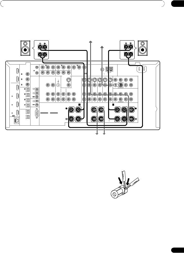
Connecting your equipment |
03 |
Bi-amping your speakers
Bi-amp compatible |
|
Bi-amp compatible |
speaker |
Center |
speaker |
|
|
Subwoofer |
High |
|
High |
Low |
|
Low |
Front left |
|
Front right |
HDMI |
|
12V |
1 |
|
IN 1 |
|
IN 2 |
|
|
|
IN 3 |
|
|
|
|
|
|
|
|
|
AC IN |
|
COAXIAL |
TRIGGER |
|
|
|
|
|
|
|
|
|
|
|
|
|
|
|
|
|
|
|
||
|
|
|
|
|
|
|
|
|
|
|
|
|
|
|
|
|
|
|
|
|
|
|
OUT |
ASSIGNABLE |
(OUTPUT |
|
(DVD) |
|
(DVR) |
|
|
|
PR |
PB |
Y |
ANTENNA |
|
|
|
|
|
|
|
||
1 |
|
12V |
|
|
|
|
|
|
|
|
(VIDEO 1) |
|
|
|
|
|
|
|
|
|
|
|
|
TOTAL |
|
|
|
|
|
|
|
|
|
|
|
|
|
|
|
|
|
|
|||
(KURO |
|
|
|
|
|
|
|
|
|
|
|
|
|
|
|
|
|
|
|
|
|
|
|
50 mA |
|
|
|
|
|
|
|
|
|
ASSIGNABLE 1 - 3 |
|
|
FM UNBAL 75 |
AM LOOP |
|
|
|
|
|||
LINK ) |
IN 1 (DVD) |
|
PR |
PB |
Y |
|
|
|
|
|
|
|
|
|
|
|
||||||
MAX) |
2 |
PR |
PB |
Y |
|
|
COMPONENT VIDEO |
|
|
|
|
|
|
|||||||||
|
|
|
ZONE 2 OUT |
|
|
|
|
|
|
|
|
|
|
|
||||||||
|
|
|
|
|
|
|
|
|
MONITOR OUT |
|
|
|
|
|
|
|
|
FRONT |
CENTER |
SURROUND SURROUNDBACK |
||
|
|
|
|
|
|
|
SIGNAL |
|
|
|
|
|
|
|
|
|
|
|
||||
OUT |
|
|
|
|
|
|
|
|
|
|
|
|
|
|
|
|
|
|
|
|
(Single) |
|
IN 2 (CD) |
|
|
|
|
|
GND |
|
|
|
|
S-VIDEO |
|
|
|
|
|
|
|
|
|
||
2 |
|
|
|
|
|
|
|
|
|
|
|
|
|
|
|
|
|
|
L |
|||
|
|
|
|
|
|
|
|
|
|
|
|
|
|
|
|
|
|
|
|
|||
|
|
|
|
|
|
|
|
|
|
|
|
|
|
|
|
|
|
|
|
|
|
PRE OUT |
|
IN 3 |
IR |
|
VIDEO |
|
|
|
|
|
|
VIDEO |
|
|
|
|
|
|
|
|
|
R |
|
|
(VIDEO 2) |
|
|
|
|
|
|
|
|
|
|
|
|
|
|
|
|
|
||||
BD |
|
|
|
|
|
|
|
|
|
|
|
|
|
|
|
|
|
|
SUBWOOFER |
|
|
|
|
|
|
|
|
|
|
|
|
|
|
|
|
|
|
|
|
|
|
|
|
||
IN |
|
IN |
|
|
|
|
|
|
|
|
|
|
|
|
|
|
|
|
|
|
|
|
IN 1 |
|
|
ZONE 2 |
ZONE 3 |
PHONO |
|
CD |
CD-R/TAPE |
|
DVD |
TV/SAT |
VIDEO1 |
VIDEO2 |
|
DVR |
|
|
|
MULTI CH IN |
|||
|
|
|
|
|
OUT |
|
|
|
||||||||||||||
|
(TV/SAT) |
1 |
|
|
OUT |
OUT |
IN |
|
IN |
OUT |
IN |
|
IN |
IN |
IN |
IN |
IN |
FRONT |
CENTER |
SURROUND SURROUNDBACK |
||
|
|
|
|
|
|
|
|
|
|
|
|
|
|
|
|
|
|
|
||||
|
IN 2 |
IN |
|
|
L |
|
|
|
|
|
|
|
|
|
|
|
|
|
|
|
|
L |
IN |
2 |
|
|
|
|
|
|
|
|
|
|
|
|
|
|
|
|
|
|
|||
(DVR) |
|
|
|
|
|
|
|
|
|
|
|
|
|
|
|
|
|
|
|
|
|
|
1 |
|
|
|
|
|
|
|
|
|
|
|
|
|
|
|
|
|
|
|
|
|
|
|
OUT |
|
|
|
|
|
|
|
|
|
|
|
|
|
|
|
|
|
|
|
|
|
|
|
|
|
|
|
|
|
|
|
|
|
|
|
|
|
|
|
|
|
|
|
|
|
IN 3 |
|
|
|
R |
|
|
|
|
|
|
|
|
|
|
|
|
|
|
|
|
R |
|
(VIDEO1) |
IN |
|
|
|
|
|
|
|
|
|
|
|
|
|
|
|
|
|
SUBWOOFER |
|
|
|
|
CONTROL |
|
|
|
|
|
|
|
|
|
|
|
|
|
|
|
|
|
|
|
|
IN |
|
|
SPEAKERS |
|
|
|
|
R SURROUND BACK/ B |
|
|
|
|
|
A |
|
|
|
|
||||
2 |
IN 4 |
OUT |
|
|
|
|
|
L (Single) |
R |
SURROUND |
L |
R |
FRONT |
L |
CENTER |
|||||||
|
|
|
|
|
|
|
||||||||||||||||
|
(CD-R) |
|
|
|
|
CAUTION: |
|
|
|
|
|
|
|
|
|
|
|
|
|
|
|
|
|
ASSIGNABLE |
|
|
|
|
|
|
|
|
|
|
|
|
|
|
|
|
|
|
|
||
|
|
|
|
|
SPEAKER IMPEDANCE 6 Ω- 16 Ω. |
|
|
|
|
|
|
|
|
|
|
|
|
|
||||
|
|
|
|
|
|
ATTENTION: |
|
|
|
|
|
|
|
|
|
|
|
|
|
|
|
|
IN |
OUT 1 |
|
|
|
|
ENCEINTE D'IMPEDANCE DE 6 Ω- 16 Ω. |
|
|
|
|
|
|
|
|
|
|
|
|
|
|||
3 |
|
|
|
|
SELECTABLE |
SELECTABLE |
|
|
|
|
|
|
|
|
|
|
|
|
|
|
|
|
ASSIGNABLE |
|
|
|
SEE INSTRUCTION |
VOIR LE MODE |
|
|
|
|
|
|
|
|
|
|
|
|
|
|
|
||
1 - 3 |
|
|
|
MANUAL |
D'EMPLOI |
|
|
|
|
|
|
|
|
|
|
|
|
|
|
|
|
|
LAN |
OUT 2 |
RS-232C |
|
|
|
|
|
|
|
|
|
|
|
|
|
|
|
|
|
|
|
|
OPTICAL |
|
|
|
|
|
|
|
|
|
|
|
|
|
|
|
|
|
|
|
|
|
|
(10/100) |
|
|
|
|
|
|
|
|
|
|
|
|
|
|
|
|
|
|
|
|
|
|
Surround right
 Surround left
Bi-amping is when you connect the high frequency driver and low frequency driver of your speakers to different amplifiers for better crossover performance. Your speakers must be bi-ampable to do this (having separate terminals for high and low) and the sound improvement will depend on the kind of speakers you’re using.
 CAUTION
•Most speakers with both High and Low terminals have two metal plates that connect the High to the Low terminals. These must be removed when you are bi-amping the speakers or you could severely damage the amplifier. See your speaker manual for more information.
•If your speakers have a removable crossover network, make sure you do not remove it for bi-amping. Doing so may damage your speakers.
Bi-wiring your speakers
Your speakers can also be bi-wired if they support biamping.
•With these connections, the Surr Back System setting makes no difference.
•To bi-wire a speaker, connect two speaker cords to the speaker terminal on the receiver.
 CAUTION
•Don’t connect different speakers from the same terminal in this way.
•When bi-wiring as well, heed the cautions for biamping shown at the left.
25
En
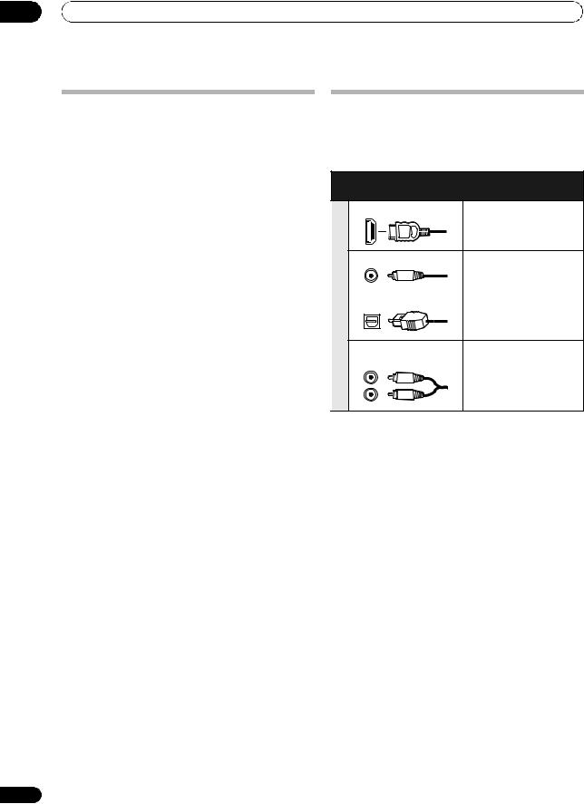
03 Connecting your equipment
Selecting the Surr Back system
The surround back terminals can be used for bi-amping, Speaker B and ZONE 2 connections, in addition to for the surround back speakers. Make this setting according to the application.
ZONE 2 setup
With these connections you can simultaneously enjoy 5.1-channel surround sound in the main zone with stereo playback on another component in ZONE 2.
1Connect a pair of speakers to the surround back speaker terminals.
See Standard 5.1/6.1/7.1-channel surround connections on page 24.
2Select ‘ZONE 2’ from the Surr Back System menu.
See Surround back speaker setting on page 121 to do this.
Speaker B setup
You can listen to stereo playback in another room.
1Connect a pair of speakers to the surround back speaker terminals.
See Standard 5.1/6.1/7.1-channel surround connections on page 24.
2Select ‘Speaker B’ from the Surr Back System menu.
See Surround back speaker setting on page 121 to do this.
Bi-Amping setup
Bi-amping connection of the front speakers for high sound quality with 5.1-channel surround sound.
1Connect Bi-amp compatible speakers to the front and surround back speaker terminals.
See Bi-amping your speakers on page 25.
2Select ‘Front Bi-Amp’ from the Surr Back System menu.
See Surround back speaker setting on page 121 to do this.
26
About the audio connection
There are several types of audio input and output terminals on this receiver. The receiver selects the first available signal in the following order when you choose AUTO as the input signal:
|
Types of cables and |
Transferable audio |
|
terminals |
signals |
|
HDMI |
HD audio |
priority |
Digital (Optical) |
|
Soundsignal |
Conventional digital audio |
|
|
Digital (Coaxial) |
|
|
RCA (Analog) |
Conventional analog audio |
|
(White/Red) |
|
•With an HDMI cable, video and audio signals can be transferred in high quality over a single cable.
 CAUTION
•When connecting optical cables, be careful when inserting the plug not to damage the shutter protecting the optical socket.
•When storing optical cable, coil loosely. The cable
may be damaged if bent around sharp corners.
En
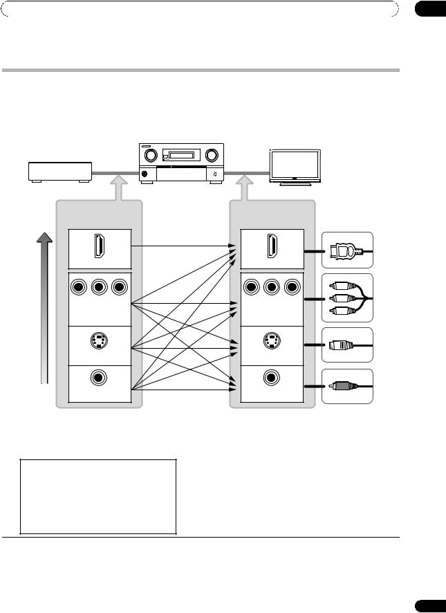
Connecting your equipment |
03 |
About the video converter
The video converter ensures that all video sources are output through all of the MONITOR OUT jacks. The only exception is HDMI: since this resolution cannot be downsampled, you must connect your monitor/TV to the receiver’s HDMI video outputs when connecting this video source.1
If several video components are assigned to the same input function (see The Input Setup menu on page 47), the converter gives priority to HDMI, component, S-Video, then composite (in that order).
High picture quality
|
Source device |
|
|
This receiver |
TV monitor |
|
|
|
|
|
||
|
Terminal for |
|
Terminal for |
|
|
connection with |
connection with TV |
||||
source device |
|
monitor |
Types of cables |
||
|
|
|
|
|
|
|
HDMI IN |
|
|
HDMI OUT |
|
PR |
PB |
Y |
PR |
PB |
Y |
COMPONENT |
COMPONENT VIDEO |
||||
|
VIDEO IN |
|
MONITOR OUT |
||
|
S-VIDEO IN |
|
|
S-VIDEO |
|
|
|
|
MONITOR OUT |
||
|
VIDEO IN |
|
|
VIDEO |
|
|
|
|
MONITOR OUT |
||
 Video signals can be output
•For optimal video performance, THX recommends switching Digital Video Conversion (in Setting the Video options on page 87) OFF.
This product incorporates copyright protection technology that is protected by method claims of certain U.S. patents and other intellectual property rights owned by Macrovision Corporation and other rights owners. Use of this copyright protection technology must be authorized by Macrovision Corporation, and is intended for home and other limited viewing uses only unless otherwise authorized by Macrovision Corporation. Reverse engineering or disassembly is prohibited.
 Note
Note
1• If the video signal does not appear on your TV or flat screen TV, try adjusting the resolution settings on your component or display. Note that some components (such as video game units) have resolutions that may not be converted. In this case, try switching Digital Video Conversion (in Setting the Video options on page 87) OFF.
•The signal input resolutions that can be converted from the component video input for the HDMI output are 480i/576i, 480p/576p, 720p and 1080i. 1080p signal cannot be converted.
•Only signals with an input resolution of 480i/576i can be converted from the component video input for the composite and S-Video MONITOR OUT.
27
En
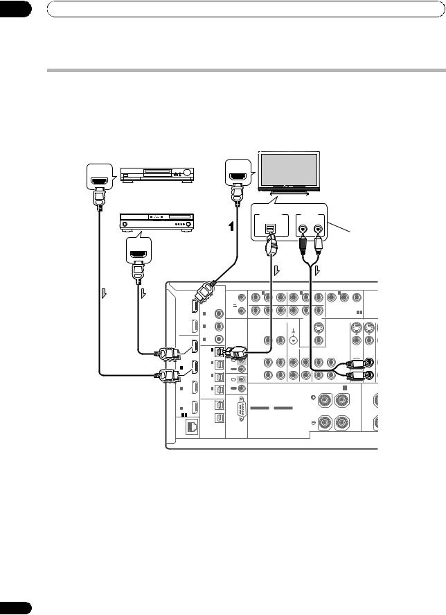
03 Connecting your equipment
Connecting your TV and playback components
Connecting using HDMI
If you have an HDMI or DVI (with HDCP) equipped component (Blu-ray disc player, etc.), you can connect it to this receiver using a commercially available HDMI cable.
If the TV and playback components support the Pioneer KURO LINK feature, the convenient KURO LINK functions can be used (see KURO LINK on page 81).
Other HDMI/DVIequipped component
HDMI OUT
HDMI/DVI-compatible
Blu-ray disc player
HDMI OUT
HDMI |
COAXIAL |
|
|
||
OUT |
ASSIGNABLE |
|
|
||
1 |
|
|
(KURO |
|
|
LINK ) |
IN 1 (DVD) |
|
OUT |
IN 2 (CD) |
|
2 |
||
|
||
|
IN 3 |
|
BD |
(VIDEO 2) |
|
|
||
IN |
IN 1 |
|
|
||
|
(TV/SAT) |
|
IN |
IN 2 |
|
(DVR) |
||
1 |
||
|
||
|
IN 3 |
|
|
(VIDEO1) |
|
IN |
|
|
2 |
IN 4 |
|
|
(CD-R) |
|
|
ASSIGNABLE |
|
IN |
OUT 1 |
|
3 |
|
|
ASSIGNABLE |
|
|
1 - 3 |
|
|
LAN |
OUT 2 |
|
OPTICAL |
||
(10/100) |
HDMI IN
HDMI/DVI-compatible monitor or flat screen TV
Select one
DIGITAL OUT |
AUDIO OUT |
OPTICAL |
R ANALOG L |
This connection is required in order to listen to the sound of the TV over the receiver.
12V |
1 |
|
IN 1 |
|
IN 2 |
|
|
|
IN 3 |
|
|
|
TRIGGER |
|
|
|
|
|
|
|
|
|
|
|
|
(OUTPUT |
|
(DVD) |
|
(DVR) |
|
|
|
PR |
PB |
Y |
ANTE |
|
12V |
|
|
|
|
|
|
|
|
(VIDEO 1) |
|
|
|
TOTAL |
|
|
|
|
|
|
|
|
|
|
||
|
|
|
|
|
|
|
|
|
|
|
|
|
50 mA |
|
PR |
PB |
Y |
|
|
|
|
|
ASSIGNABLE 1 - 3 |
|
|
MAX) |
2 |
PR |
PB |
Y |
|
|
COMPONENT VIDEO |
|
||||
|
ZONE 2 OUT |
|
|
|
||||||||
|
|
|
|
|
|
|
MONITOR OUT |
|
|
|
|
|
|
|
|
|
|
SIGNAL |
|
|
|
|
|
|
|
|
|
|
|
|
GND |
|
|
|
|
S-VIDEO |
|
|
IR |
|
VIDEO |
|
|
|
|
|
|
VIDEO |
|
|
|
|
|
|
|
|
|
|
|
|
|
|||
IN |
|
|
ZONE 2 |
ZONE 3 |
PHONO |
|
CD |
CD-R/TAPE |
|
DVD |
TV/SAT V |
|
1 |
|
|
OUT |
OUT |
IN |
|
IN |
OUT |
IN |
|
IN |
IN |
IN |
|
|
L |
|
|
|
|
|
|
|
|
|
2 |
|
|
|
|
|
|
|
|
|
|
|
|
OUT |
|
|
|
|
|
|
|
|
|
|
|
|
|
|
|
R |
|
|
|
|
|
|
|
|
|
IN |
|
|
|
|
|
|
|
|
|
|
|
|
CONTROL |
|
SPEAKERS |
|
|
|
|
R SURROUND BACK/ B |
|
|
|||
OUT |
|
|
|
|
|
L (Single) |
R |
|||||
|
|
|
|
|
|
|
||||||
|
|
|
|
CAUTION: |
|
|
|
|
|
|
|
|
|
|
|
|
SPEAKER IMPEDANCE 6 Ω- 16 Ω. |
|
|
|
|
|
|||
|
|
|
|
ATTENTION: |
|
|
|
|
|
|
|
|
|
|
|
|
ENCEINTE D'IMPEDANCE DE 6 Ω- 16 Ω. |
|
|
|
|
|
|||
|
|
|
SELECTABLE |
SELECTABLE |
|
|
|
|
|
|
|
|
|
|
SEE INSTRUCTION |
VOIR LE MODE |
|
|
|
|
|
|
|
||
|
|
MANUAL |
D'EMPLOI |
|
|
|
|
|
|
|
|
|
RS-232C
•When connecting a Blu-ray disc player, connect the player to the receiver’s BD IN terminal.
•When connecting to an HDMI/DVI-compatible monitor or a flat screen TV using the HDMI OUT 2 terminal, switch the HDMI output setting to HDMI OUT 2 or HDMI OUT ALL. See Switching the HDMI output on page 91.
•The HDMI indicator lights on the front panel when an HDMI-equipped component is connected.
•For input components, connections other than HDMI connections are also possible (see Connecting your DVD player with no HDMI output on page 29).
•If your Blu-ray disc player offers multi-channel analog audio outputs, see Connecting the multichannel analog inputs on page 33.
•The sound of the TV cannot be heard over the receiver if the TV is connected using an HDMI cable.
If you want to listen to the sound of the TV over the receiver, connect the receiver and TV with audio cables.
28
En
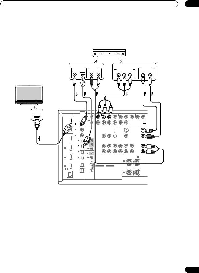
Connecting your equipment |
03 |
Connecting your DVD player with no HDMI output
This diagram shows connections of a TV (with HDMI input) and DVD player (or other playback component with no HDMI output) to the receiver.
|
DVD player, etc. |
|
|
|
|
|
Select one |
|
|
|
Select one |
|
|
DIGITAL OUT |
AUDIO OUT |
|
COMPONENT VIDEO OUT |
VIDEO OUT |
||
|
|
|
|
|||
COAXIAL OPTICAL |
R ANALOG |
L |
PR |
PB |
S-VIDEO VIDEO |
|
|
|
|
Y |
|
||
HDMI/DVI-compatible monitor or flat screen TV
HDMI IN
HDMI |
|
12V |
1 |
|
IN 1 |
|
IN 2 |
|
|
|
IN 3 |
|
|
|
COAXIAL |
TRIGGER |
|
|
|
|
|
|
|
|
|
|
|
|
|
|
|
|
|
|
|
|
|
|
|
|
|
|
||
|
|
|
|
|
|
|
|
|
|
|
|
|
|
|
OUT |
ASSIGNABLE |
(OUTPUT |
|
(DVD) |
|
(DVR) |
|
|
|
PR |
PB |
Y |
|
|
1 |
|
12V |
|
|
|
|
|
|
|
|
(VIDEO 1) |
|
|
|
|
TOTAL |
|
|
|
|
|
|
|
|
|
|
|||
(KURO |
|
|
|
|
|
|
|
|
|
|
|
|
|
|
|
50 mA |
|
|
|
|
|
|
|
|
|
ASSIGNABLE 1 - 3 |
|
||
LINK ) |
IN 1 (DVD) |
|
PR |
PB |
Y |
|
|
|
|
|
|
|||
MAX) |
2 |
PR |
PB |
Y |
|
|
COMPONENT VIDEO |
|
||||||
|
|
|
ZONE 2 OUT |
|
|
|
||||||||
|
|
|
|
|
|
|
|
|
MONITOR OUT |
|
|
|
|
|
OUT |
|
|
|
|
|
|
SIGNAL |
|
|
|
|
|
|
|
2 |
IN 2 (CD) |
|
|
|
|
|
GND |
|
|
|
|
S-VIDEO |
|
|
|
IN 3 |
IR |
|
VIDEO |
|
|
|
|
|
|
VIDEO |
|
|
|
|
(VIDEO 2) |
|
|
|
|
|
|
|
|
|
|
|||
BD |
|
|
|
|
|
|
|
|
|
|
|
|
|
|
|
|
|
|
|
|
|
|
|
|
|
|
|
|
|
IN |
IN 1 |
IN |
|
|
ZONE 2 |
ZONE 3 |
PHONO |
|
CD |
CD-R/TAPE |
|
DVD |
T |
|
|
|
|
|
|
||||||||||
|
(TV/SAT) |
1 |
|
|
OUT |
OUT |
IN |
|
IN |
OUT |
IN |
|
IN |
|
|
IN 2 |
IN |
|
|
L |
|
|
|
|
|
|
|
|
|
IN |
2 |
|
|
|
|
|
|
|
|
|
|
|
||
(DVR) |
|
|
|
|
|
|
|
|
|
|
|
|
|
|
1 |
|
|
|
|
|
|
|
|
|
|
|
|
|
|
|
OUT |
|
|
|
|
|
|
|
|
|
|
|
|
|
|
|
|
|
|
|
|
|
|
|
|
|
|
|
|
|
IN 3 |
|
|
|
R |
|
|
|
|
|
|
|
|
|
|
(VIDEO1) |
IN |
|
|
|
|
|
|
|
|
|
|
|
|
IN |
|
CONTROL |
|
SPEAKERS |
|
|
|
|
R SURROUND BACK/ B |
|
|
|||
2 |
IN 4 |
OUT |
|
|
|
|
|
L (Single) |
|
|||||
|
|
|
|
|
|
|
|
|||||||
|
(CD-R) |
|
|
|
|
CAUTION: |
|
|
|
|
|
|
|
|
|
ASSIGNABLE |
|
|
|
|
|
|
|
|
|
|
|
||
|
|
|
|
|
SPEAKER IMPEDANCE 6 Ω- 16 Ω. |
|
|
|
|
|
||||
|
|
|
|
|
|
ATTENTION: |
|
|
|
|
|
|
|
|
IN |
OUT 1 |
|
|
|
|
ENCEINTE D'IMPEDANCE DE 6 Ω- 16 Ω. |
|
|
|
|
|
|||
3 |
|
|
|
|
SELECTABLE |
SELECTABLE |
|
|
|
|
|
|
|
|
ASSIGNABLE |
|
|
|
SEE INSTRUCTION |
VOIR LE MODE |
|
|
|
|
|
|
|
||
1 - 3 |
|
|
|
MANUAL |
D'EMPLOI |
|
|
|
|
|
|
|
|
|
LAN |
OUT 2 |
RS-232C |
|
|
|
|
|
|
|
|
|
|
|
|
OPTICAL |
|
|
|
|
|
|
|
|
|
|
|
|
|
|
(10/100) |
|
|
|
|
|
|
|
|
|
|
|
|
|
|
•If you want to listen to the sound of the TV over the receiver, connect the receiver and TV with audio cables.
•Component video should give superior picture quality when compared to composite or S-Video. You can also take advantage of progressive scan video (if your source and TV are both compatible), which delivers a very stable, flicker-free picture. See the manuals that came with your TV and source component to check whether they are compatible with progressive-scan video.
•If your DVD player offers multi-channel analog audio outputs, see Connecting the multichannel analog inputs on page 33.
29
En
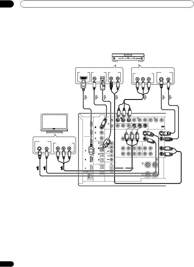
03 Connecting your equipment
Connecting your TV with no HDMI input
This diagram shows connections of a TV (with no HDMI input) and DVD player (or other playback component) to the receiver.
•With these connections, the picture is not output to the TV even if the DVD player is connected with an HDMI cable. Connect the DVD player’s video signals using a composite, S-VIDEO or component cord.
|
|
DVD player, etc. |
|
|
|
||
|
Select one |
|
|
|
|
Select one |
|
HDMI OUT |
DIGITAL OUT |
AUDIO OUT |
|
COMPONENT VIDEO OUT |
VIDEO OUT |
||
|
COAXIAL OPTICAL |
R ANALOG |
L |
S-VIDEO VIDEO |
|||
|
PR |
PB |
Y |
||||
|
|
|
|
|
|||
|
|
|
TV |
|
|
|
|
|
|
|
|
|
|
|
|
|
|
|
|
|
|
|
|
|
HDMI |
|
12V |
1 |
|
IN 1 |
|
IN 2 |
|
|
|
IN 3 |
|
|
|
|
|
|
|
|
COAXIAL |
TRIGGER |
|
|
|
|
|
|
|
|
|
|
|
|
|
|
|
|
|
|
|
|
|
|
|
|
|
|
|
|
|
|
|
|
|
|
|
|
|
|
OUT |
ASSIGNABLE |
(OUTPUT |
|
(DVD) |
|
(DVR) |
|
|
|
PR |
PB |
Y |
|
|
|
|
|
|
|
1 |
|
12V |
|
|
|
|
|
|
|
|
(VIDEO 1) |
|
|
|
|
|
|
|
|
|
TOTAL |
|
|
|
|
|
|
|
|
|
|
|||
|
|
|
|
|
(KURO |
|
|
|
|
|
|
|
|
|
|
|
|
|
|
|
|
|
|
|
|
50 mA |
|
|
|
|
|
|
|
|
|
ASSIGNABLE 1 - 3 |
|
||
|
|
|
|
|
LINK ) |
IN 1 (DVD) |
|
PR |
PB |
Y |
|
|
|
|
|
|
|||
|
|
|
|
|
MAX) |
2 |
PR |
PB |
Y |
|
|
COMPONENT VIDEO |
|
||||||
|
|
|
|
|
|
|
|
ZONE 2 OUT |
|
|
|
||||||||
|
|
|
|
|
|
|
|
|
|
|
|
|
|
MONITOR OUT |
|
|
|
|
|
|
|
|
|
|
OUT |
|
|
|
|
|
|
SIGNAL |
|
|
|
|
|
|
|
|
|
|
|
|
IN 2 (CD) |
|
|
|
|
|
GND |
|
|
|
|
S-VIDEO |
|
|
|
|
|
|
|
|
2 |
|
|
|
|
|
|
|
|
|
|
|
|||
|
|
Select one |
|
|
IN 3 |
IR |
|
VIDEO |
|
|
|
|
|
|
VIDEO |
|
|
||
|
|
|
|
(VIDEO 2) |
|
|
|
|
|
|
|
|
|
|
|||||
VIDEO IN |
|
|
|
BD |
|
|
|
|
|
|
|
|
|
|
|
|
|
|
|
|
|
|
IN |
|
IN |
|
|
|
|
|
|
|
|
|
|
|
|
||
S-VIDEO |
VIDEO |
COMPONENT VIDEO IN |
IN 1 |
|
|
ZONE 2 |
ZONE 3 |
PHONO |
|
CD |
CD-R/TAPE |
|
DVD |
T |
|||||
PR |
PB |
Y |
(TV/SAT) |
1 |
|
|
OUT |
OUT |
IN |
|
IN |
OUT |
IN |
|
IN |
|
|||
|
|
|
|
|
|
|
|
|
|
|
|
|
|
|
|
|
|||
|
|
|
|
|
|
IN 2 |
IN |
|
|
L |
|
|
|
|
|
|
|
|
|
|
|
|
|
|
IN |
2 |
|
|
|
|
|
|
|
|
|
|
|
||
|
|
|
|
|
(DVR) |
|
|
|
|
|
|
|
|
|
|
|
|
|
|
|
|
|
|
|
1 |
|
|
|
|
|
|
|
|
|
|
|
|
|
|
|
|
|
|
|
|
OUT |
|
|
|
|
|
|
|
|
|
|
|
|
|
|
|
|
|
|
|
|
|
|
|
|
|
|
|
|
|
|
|
|
|
|
|
|
|
|
|
IN 3 |
|
|
|
R |
|
|
|
|
|
|
|
|
|
|
|
|
|
|
|
(VIDEO1) |
IN |
|
|
|
|
|
|
|
|
|
|
|
|
|
|
|
|
|
IN |
|
CONTROL |
|
SPEAKERS |
|
|
|
|
R SURROUND BACK/ B |
|
|
|||
|
|
|
|
|
2 |
IN 4 |
OUT |
|
|
|
|
|
L (Single) |
|
|||||
|
|
|
|
|
|
|
|
|
|
|
|
|
|||||||
|
|
|
|
|
|
(CD-R) |
|
|
|
|
CAUTION: |
|
|
|
|
|
|
|
|
|
|
|
|
|
|
ASSIGNABLE |
|
|
|
|
|
|
|
|
|
|
|
||
|
|
|
|
|
|
|
|
|
|
SPEAKER IMPEDANCE 6 Ω- 16 Ω. |
|
|
|
|
|
||||
|
|
|
|
|
|
|
|
|
|
|
ATTENTION: |
|
|
|
|
|
|
|
|
|
|
|
|
|
IN |
OUT 1 |
|
|
|
|
ENCEINTE D'IMPEDANCE DE 6 Ω- 16 Ω. |
|
|
|
|
|
|||
|
|
|
|
|
3 |
|
|
|
|
SELECTABLE |
SELECTABLE |
|
|
|
|
|
|
|
|
|
|
|
|
|
ASSIGNABLE |
|
|
|
SEE INSTRUCTION |
VOIR LE MODE |
|
|
|
|
|
|
|
||
|
|
|
|
|
1 - 3 |
|
|
|
MANUAL |
D'EMPLOI |
|
|
|
|
|
|
|
|
|
|
|
|
|
|
LAN |
OUT 2 |
RS-232C |
|
|
|
|
|
|
|
|
|
|
|
|
|
|
|
|
|
OPTICAL |
|
|
|
|
|
|
|
|
|
|
|
|
|
|
|
|
|
|
|
(10/100) |
|
|
|
|
|
|
|
|
|
|
|
|
|
|
•Connect using an HDMI cable to listen to HD audio on the receiver. Do not use an HDMI cable to input video signals.
Depending on the video component, it may not be possible to output signals connected by HDMI and other methods simultaneously, and it may be necessary to make output settings. Please refer to the operating instructions supplied with your component for more information.
•Component video should give superior picture quality when compared to composite or S-Video. You can also take advantage of progressive scan video (if your source and TV are both compatible), which delivers a very stable, flicker-free picture. See the manuals that came with your TV and source component to check whether they are compatible with progressive-scan video.
•If your DVD player has multichannel analog outputs, you can connect these instead. See also see
Connecting the multichannel analog inputs on page 33.
30
En
Loading...