


SBD-30
PIONEER CORPORATION 1-1, Shin-ogura, Saiwai-ku, Kawasaki-shi, Kanagawa 212-0031, Japan
PIONEER ELECTRONICS (USA) INC. P.O. Box 1760, Long Beach, CA 90801-1760, U.S.A.
PIONEER EUROPE NV Haven 1087, Keetberglaan 1, 9120 Melsele, Belgium
PIONEER ELECTRONICS ASIACENTRE PTE. LTD. 253 Alexandra Road, #04-01, Singapore 159936
PIONEER CORPORATION 2010
SPEAKER SYSTEM
WARNING
SAFETY INFORMATION
This product may contain a chemical known to the State of California to cause cancer, or birth defects or other reproductive harm.
This service manual is intended for qualified service technicians ; it is not meant for the casual do-ityourselfer.
Qualified technicians have the necessary test equipment and tools, and have been trained
to properly and safely repair complex products such as those covered by this manual.
Improperly performed repairs can adversely affect the safety and reliability of the product and may
void the warranty. If you are not qualified to perform the repair of this product properly and safely, you
should not risk trying to do so and refer the repair to a qualified service technician.
Health & Safety Code Section 25249.6 - Proposition 65
ORDER NO.
RRV4083
S-BD303
S-BD303
S-BD30
S-BD606
/XTWUM
/XTWES
/SXTWEW5
K-ZZZ JUNE 2010 Printed in Japan
1234
1 234
C
D
F
A
B
E
1.1 FRONT SPEAKER
The grille is attached to the cabinet by 4 external screws.
To detach it, unfasten those screws. The speaker unit is attached
together with the grille assy to the cabinet by 4 external screws. To
detach it, first unfasten those screws. Next remove the cabinet.
Then remove the cable. When attaching it, face its terrminal downward.
1.2 CENTER SPEAKER
GRILLE
The grille is attached to the cabinet with the adhesive double
coated tape by press-fitting. Detach by pulling it toward you.
WOOFER
The woofer is attached to the baffle by 4 internal screws.
To detach it, first remove the grille. Next unfasten 8 scews of baffle. Then remove the cabinet and cable.
When you install speaker unit on cabinet again, please make the
terminal of speaker unit downward. Please turn up the terminal
of speaker unit not to touch on the cabinet.
1.3 SURROUND SPEAKER
The grille is attached to the cabinet by 4 external screws.
To detach it, unfasten those screws. The speaker unit is attached
together with the grille assy to the cabinet by 4 external screws.
To detach it, first unfasten those screws.
Next remove the cabinet. Then remove the cable. When attaching
it, face its terrminal downward.
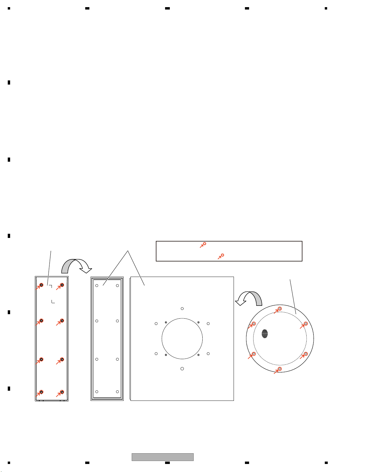
1.4 SUBWOOFER
The grille assy is installed on the cabinet with white school
glue for wood and press-in fitting. In order to remove the Grille
Assy, please insert a flat-head screw driver from the gap under
the grille assy to open. When you install the grille assy on the
cabinet again, please apply white school glue for wood on 6 locations of grille assy and conduct press-in fitting.
Woofer unit is secured with 4 screws from outside. Please remove the screws and interior cord, and pull out the unit from
the cabinet. When you install the woofer unit again, please
make the terminal of unit downward. The baffle is installed on
the cabinet with white school glue for wood and press-in fitting. In order to remove the baffle, please insert a flat-head screw
driver from the gap under the baffle to open. When you install
the baffle on the cabinet again, please apply white school glue
for wood on 8 locations of baffle and conduct press-in fitting.
Please install Grille Assy or Baffle in the cabinet applying the white
school glue for wood to the “ ” marked section.
Caution point of marked section
Please do not wipe resin black glossy surface with cloth strongly because the surface is easy to be scratched. Please pay attention to
handle resin black glossy surface.
Cabinet
Baffle
Grille Assy
1. REASSEMBLY AND DISASSEMBLY PRECAUTIONS
2
S-BD303
5 678
56
7
8
C
D
F
A
B
E
Parts marked by "NSP" are generally unavailable because they are not in our Master Spare Parts List.
The mark found on some component parts indicates the importance of the safety factor of the part.
Therefore, when replacing, be sure to use parts of identical designation.
NOTES:
1
4
5
6
7
7
8
3
2
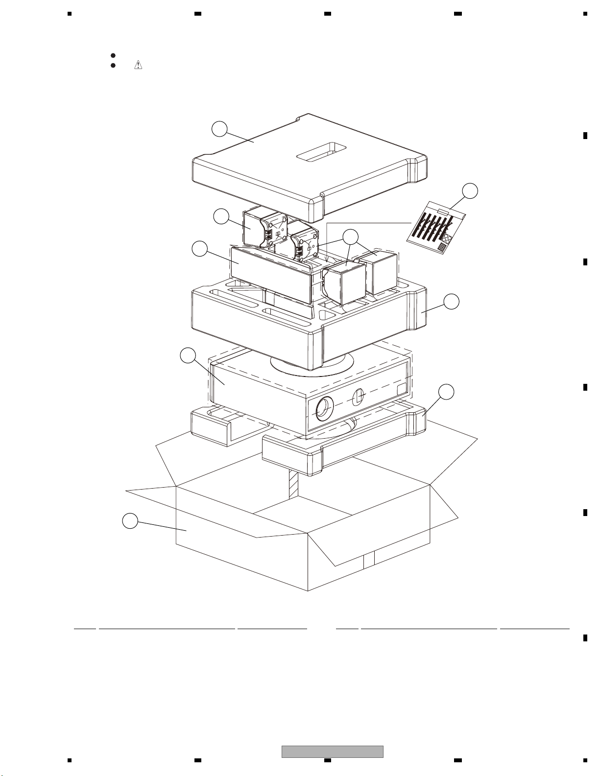
PACKING Parts List
Mark No. Description Part No.
NSP 1 Accessory Assy SME3953
1-1 Speaker Wire SDS6064
1-2 Speaker Wire SDS6065
1-3 Speaker Wire SDS6066
1-4 Speaker Wire (FR) SDS1220
1-5 Speaker Wire (FL) SDS1221
1-6 Speaker Wire (SW) SDS1223
1-7 Non Skid Pads SEP1388
1-8 Non Skid Pad SEP6042
1-9 Polyethylene Bag SHL1251
Mark No. Description Part No.
2 Protector (B) SHA2656
3 Protector (M) SHA2657
4 Protector (T) SHA2658
5 Protection Sheet SHC1895
6 Packing Case(S-BD303) SHG2868
Packing Case(S-BD30) SHG2875
Packing Case(S-BD606) SHG2878
7 Protection Sheet SHC1898
8 Protection Sheet SHC1899
2. EXPLODED VIEWS AND PARTS LIST
2.1 PACKING
S-BD303
3
 Loading...