


> Before start > Hookup > Setup > Playback > Part Names
Basic Manual
SC-LX501
AV RECEIVER
RECEPTEUR AV
En
Fr
Hookup |
|
Step1: Choose your Speaker Layout |
...................................... 3 |
Step2: Connect the Speakers ................................................. |
9 |
Step3: Connect the TV ......................................................... |
12 |
Step4: Connect the AV Components .................................... |
14 |
Step5: Multi-zone Connection ............................................... |
17 |
Step6: Connect Other Cables ............................................... |
19 |
Setup |
|
Step7: Power On & Initial Setup ........................................... |
20 |
HDMI Setup .......................................................................... |
21 |
Playback |
|
Basic Playback ..................................................................... |
22 |
Network Functions ................................................................ |
23 |
Others ................................................................................... |
25 |
Part Names |
|
Front Panel ........................................................................... |
28 |
Display .................................................................................. |
29 |
Rear Panel ............................................................................ |
30 |
Remote Controller ................................................................ |
31 |
This manual includes information needed when starting up and also instructions for frequently used operations. The "Advanced Manual" is available on the internet with details about the playback features/ listening modes/settings details, specifications, and troubleshooting. The Advanced Manual is created in a format that makes it easy to read on a PC or Smartphone.
http://www.pioneer-audiovisual.com/manual/sclx501/adv/en.html
Advanced Manual found here
> Before start > Hookup > Setup > Playback > Part Names
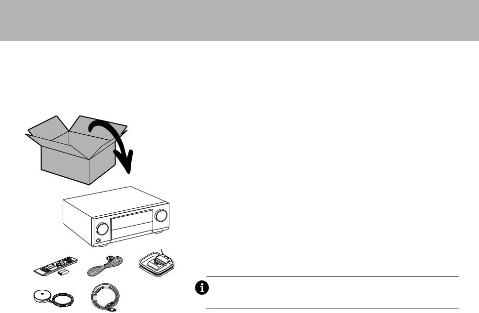
What's in the box
1. |
Main unit 2. Remote controller (RC-914R) ×1, Batteries (AAA/R03) ×2 |
3. |
Indoor FM antenna ×1 4. AM loop antenna ×1 5. Speaker setup microphone ×1 |
6. |
Power cord ×1 |
Main features
This unit features a Direct Energy HD Amplifier (Class D amplifier) that was developed using the latest digital amplifier technology. It is capable of simultaneous high-power output and very high quality sound. This amplifier provides you with the optimum playback of the latest multi-channel digital content.
$You can connect 7.1ch of speakers to this unit, with 7ch at 180 W (6 ohms, 1 kHz, 0.9%THD) (North American models) / 180 W (6 ohms, 1 kHz, 1%THD) (European and Asian models) per channel plus pre out jack for
powered subwoofer.
$ Supports playback in Dolby Atmos format which provides 360e sound placement
$ The HDMI jack supports 4K video input and output. Jacks IN1 to 3 and OUT MAIN/SUB support HDCP2.2
$HDMI CEC functionality: Control features such as linking input switching with the input selector and players conforming to the CEC standard, switching audio output and volume using the remote controller of a CECcompliant TV, and automatically switching this unit to standby when the TV is turned off
$ HDMI Standby Through: Video and audio signals from AV components can be transmitted to the TV even if this unit is in standby
1 $ ARC: Connection with an ARC-compatible TV is complete with one HDMI cable
$ Easy Initial Setup using onscreen guidance and On-Screen Display (OSD) showing operations on the TV
$Internet radio and AirPlay via wired LAN or Wi-Fi (wireless LAN) and network features such as Music Server that enables PC music file playback, USB playback, plus other playback features such as AM/FM radio and
|
|
|
BLUETOOTH® play |
|
|
|
$ Playback formats supported by Music Server and USB include WAV, FLAC and DSD high-res source |
|
|
|
$ Multi-zone Connection which allows you to play in the main room and listen in a separate room (ZONE 2) |
2 |
3 |
4 |
$ You can connect a speaker B system |
$ Equipped with RS-232C port, IR IN/OUT jack, and 12V TRIGGER OUT jacks |
|||
|
|
|
$ We plan to provide support for the DTS:X audio format through a firmware update for this unit. Refer to our |
|
|
website for more information. |
5 |
6 |
CAUTION: Connect speakers with 4 Ω to 16 Ω impedance. The power cord must be connected only after |
all other cable connections are completed. |
0 We will not accept responsibility for damage arising from the connection of equipment manufactured by other companies.
2
> Before start > Hookup > Setup > Playback > Part Names
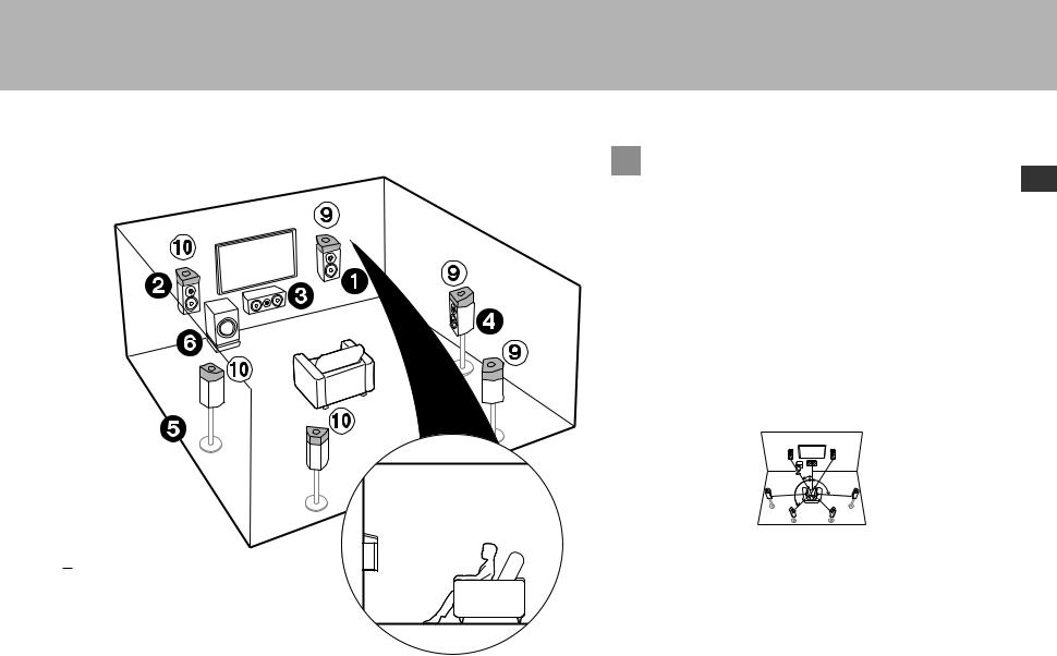
Step1: Choose your Speaker Layout
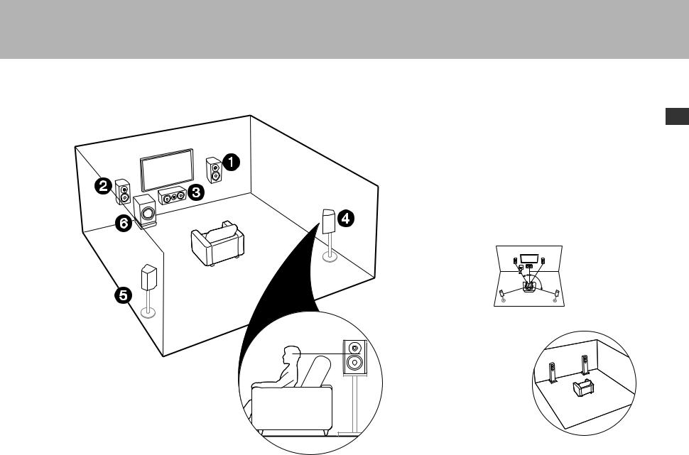
12 Front Speakers
3 Center Speaker
45 Surround Speakers
6Powered Subwoofer
 For 5.1-Channel System
En
This is a 5.1-channel system that is the basic surround system.
Front speakers output front stereo sound and a center speaker outputs center sound such as dialogs and vocals. Surround speakers create back sound field. Powered subwoofer reproduces bass sounds and creates rich sound field. The front speakers should be positioned at ear height, while the surround speakers should be positioned just above ear height. Center speaker should be set up facing the listening position. Place the powered subwoofer towards the front. Placing it between the center speaker and a front speaker gives you a natural sound even when playing music.
0The front speakers, center speaker, and surround speakers are counted as 5 channels, and the powered subwoofer is counted as 0.1 of a channel, giving us the name 5.1ch system.
Go To "Hookup" (P9)
1
2
1: 22e to 30e, 2: 120e
 Speaker B System
In a 5.1-Channel System, you can connect one more set of front speakers to use as a Speaker B System. In this state, the 5.1- Channel System becomes the Speaker A System and you can switch the same audio to output from A, B, or A+B. Note that sound is not output from Speaker B when Zone Speaker is used (P18).
Go To "Hookup" (P9)
3
> Before start > Hookup > Setup > Playback > Part Names
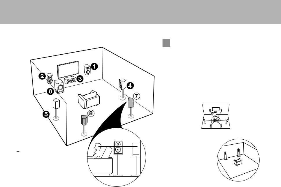
1 6 (P3)
78 Surround Back Speakers
 For 7.1-Channel System (with
Surround Back Speakers)
This is a system with surround back speakers added to the basic 5.1-channel system. The connection of surround back speakers improves the sense of envelopment and connectivity of sound created by the back sound field and provides a more real sound field. You can select the Dolby Atmos listening mode, which realizes the most up-to-date 3D surround sound, when the input format is Dolby Atmos. With formats other than Dolby Atmos, you can still create a sound field by outputting sound from the surround back speakers when you select the Dolby Surround listening mode. The optimal positioning is for surround back speakers to be at ear height. Place the surround speakers in a more slightly forward position than you would in a 5.1-channel system. 0 If you are including surround back speakers in the setup, surround
speakers are required.
Go To "Hookup" (P9)
1
2
3
1: 22e to 30e, 2: 90e to 110e, 3: 135e to 150e
 Speaker B System
In a 7.1-Channel System (with Surround Back Speakers), you can connect one more set of front speakers to use as a Speaker B System. In this state, the 7.1-Channel System becomes the Speaker A System and you can switch the same audio to output from A, B, or A+B. Note that sound is not output from the surround back speaker when A+B is selected. Note that sound is not output from Speaker B when Zone Speaker is used (P18).
Go To "Hookup" (P9)
4

> Before start > Hookup > Setup > Playback > Part Names
3´ (0.9 m) or more
1 6 (P3)
9: Height Speakers
Choose one of the following:
$ Front High Speakers
$ Rear High Speakers
For 7.1-Channel System |
En |
(with Height Speaker-A) |
Front High or Rear High speakers
This is a basic 5.1-channel system with the addition of height speakers, either as front high speakers or rear high speakers. Select which speakers to setup according to the environment of the room. You can select the Dolby Atmos listening mode (5.1.2 channel playback), which realizes the most up-to-date 3D surround sound including overhead sounds, when the input format is Dolby Atmos. With formats other than Dolby Atmos, you can still create a sound field by outputting sound from the height speakers when you select the Dolby Surround listening mode. Front high speakers or rear high speakers should be situated at least 0.9 m higher than the front speakers. Front high speakers should be situated directly above the front speakers and the distance between the rear high speakers should match the distance between the front speakers. Both should be set up facing the listening position.
Go To "Hookup" (P10)
1
2
1: 22e to 30e, 2: 120e
5
> Before start > Hookup > Setup > Playback > Part Names
 For 7.1-Channel System
(with Height Speaker-B)
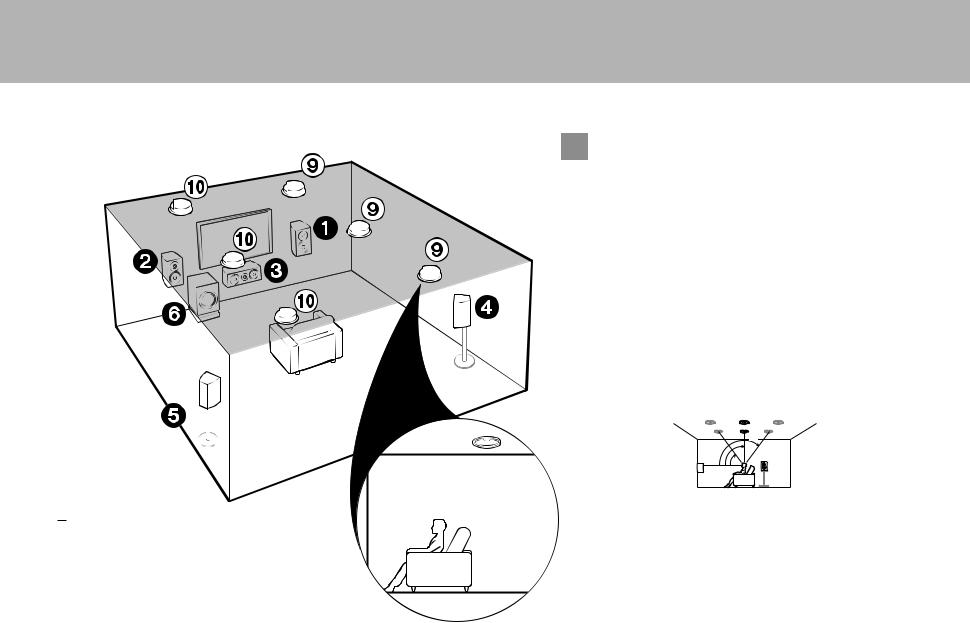
Ceiling speakers
This is a basic 5.1-channel system using ceiling speakers, for example, with the addition of height speakers, either as top front speakers, top middle speakers, or top rear speakers. Select which speakers to setup according to the environment of the room. You can select the Dolby Atmos listening mode (5.1.2 channel playback), which realizes the most up-to-date 3D surround sound including overhead sounds, when the input format is Dolby Atmos. With formats other than Dolby Atmos, you can still create a sound field by outputting sound from the height speakers when you select the Dolby Surround listening mode. Fit top front speakers on the ceiling forward of the seating position, top middle speakers on the ceiling directly above the seating position, and top rear speakers on the ceiling behind the seating position. The distance between each pair should match the distance between the two front speakers.
0 Dolby Laboratories recommends placing this type of height speakers to obtain the best Dolby Atmos effect.
Go To "Hookup" (P10)
3
2


 1
1
1: 30e to 55e, 2: 65e to 100e, 3: 125e to 150e
1 6 (P3)
9: Height Speakers
Choose one of the following:
$ Top Front Speakers
$ Top Middle Speakers
$ Top Rear Speakers
6
> Before start > Hookup > Setup > Playback > Part Names
 For 7.1-Channel System
(with Height Speakers-C)
En
Dolby enabled speakers
This is a basic 5.1-channel system that using Dolby enabled speakers, with the addition of height speakers, either as Dolby enabled speakers (front) or Dolby enabled speakers (surround) or Dolby enabled speakers (surround back). Select which speakers to setup according to the environment of the room. Dolby enabled speakers are special speakers designed to face the ceiling so that sound is heard after bouncing off the ceiling so that sound appears to be coming from overhead. You can select the Dolby Atmos listening mode (5.1.2 channel playback), which realizes the most up-to-date 3D surround sound including overhead sounds, when the input format is Dolby Atmos. With formats other than Dolby Atmos, you can still create a sound field by outputting sound from the height speakers when you select the Dolby Surround listening mode. Place them either above the front speakers or above the surround speakers or surround back speakers.
Go To "Hookup" (P10)
1
2
3
1: 22e to 30e, 2: 90e to 120e, 3: 135e to 150e
1 6 (P3)
9: Height Speakers
Choose one of the following:
$ Dolby Enabled Speakers (Front)
$ Dolby Enabled Speakers (Surround)
$ Dolby Enabled Speakers (Surround Back)
7

> Before start > Hookup > Setup > Playback > Part Names
 For Bi-Amping the Speakers
It is possible to connect front speakers supporting Bi-Amping to improve quality of the bass and treble. The maximum number of channels available with this connection is 5.1 because Bi-Amping speakers require one amplifier for the tweeter jacks and one amplifier for the woofer jacks. The effects and placements for speakers are the same as the 5.1-channel plan that doesn't use Bi-Amping speakers.
Go To "Hookup" (P11)
1
2
1: 22e to 30e, 2: 120e
12 Front Speakers (Bi-Amping)
3 Center Speaker
45 Surround Speakers
6Powered Subwoofer
8
> Before start > Hookup > Setup > Playback > Part Names
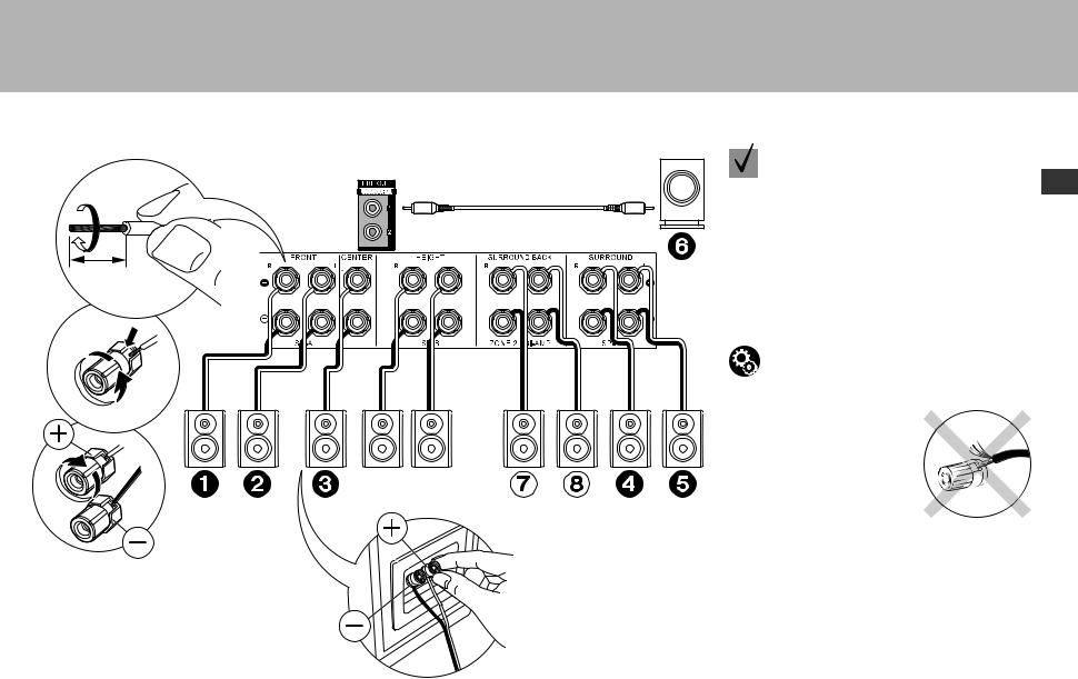
Step2: Connect the Speakers
3/8˝ (10 mm)
2 |
in case of: |
En |
Pages 3 to 4 |
||
|
|
Connect 123456 for a 5.1-channel system. With a 7.1-Channel System (with Surround Back Speakers), also connect 7 and 8. Up to two powered subwoofers can be connected. The same signal is output from each of the SUBWOOFER jacks. With this connection, you can connect one more set of front speakers to use as a Speaker B System. Switch Speakers A/B with "Speakers" in AV Adjust (P26). Note that sound is not output from the surround back speaker when A+B is selected.
|
Setup |
|
0 Settings for the speaker configuration you have |
1 |
connected need to be made in "1. Full Auto |
MCACC" (P20) in Initial Setup. |
Speaker B
Make sure the exposed wires of the speakers do not stick out of the speaker terminals when connecting. If the exposed wires of the speakers touch the rear panel or the + and – wires touch each other, the protection circuit will be activated.
1 Speaker cable, 2 Subwoofer cable
9

> Before start > Hookup > Setup > Playback > Part Names
3/8˝ (10 mm)
1
1 Speaker cable, 2 Subwoofer cable
|
in case of: |
2 |
Pages 5 to 7 |
Connect 1234569:. Up to two powered subwoofers can be connected. The same signal is output from each of the SUBWOOFER jacks.
0 Apart from these connections, you can also connect surround back speakers 7 and 8. However, you can only output audio from one set of 78 or 9: at a time. When you have connected both, you can select which speakers to prioritize with "Speakers" (P26) in the AV Adjust.
Setup
0 Settings for the speaker configuration you have connected need to be made in "1. Full Auto MCACC" (P20) in Initial Setup. Note that if you are using height speakers, set "Speaker Channels" to "5.1.2 ch" in the setting screen. Select "7.1.2 ch" if you have connected both surround back speakers and height speakers.
Make sure the exposed wires of the speakers do not stick out of the speaker terminals when connecting. If the exposed wires of the speakers touch the rear panel or the + and – wires touch each other, the protection circuit will be activated.
10
> Before start > Hookup > Setup > Playback > Part Names
3/8˝ (10 mm)
2 |
in case of: |
En |
Page 8 |
||
|
|
Connect front speakers compatible with Bi-Amping connection to the FRONT jacks and the SURROUND BACK jacks. Make sure you remove the jumper bar fitted between the woofer jacks and tweeter jacks of the front speakers. In case of Bi-Amping connection, refer to the instruction manual of your speakers. Up to two powered subwoofers can be connected. The same signal is output from each of the SUBWOOFER jacks.
|
Setup |
|
0 Bi-Amping connection requires you to change |
|
some settings. Select "Yes" in "Bi-Amp" in "1. Full |
1 |
Auto MCACC" (P20) in the Initial Setup. |
|


 For high-
frequency
For lowfrequency
Make sure the exposed wires of the speakers do not stick out of the speaker terminals when connecting. If the exposed wires of the speakers touch the rear panel or the + and – wires touch each other, the protection circuit will be activated.
1 Speaker cable, 2 Subwoofer cable
11
> Before start > Hookup > Setup > Playback > Part Names
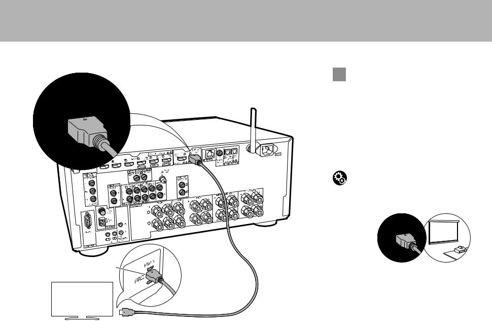
Step3: Connect the TV
 if you have:
ARC TV
This unit is connected between your TV and AV components. If you connect two or more AV components, you can select the video displayed on the TV and the audio output from this unit by changing the input selector. Shown here are the connections for a TV that supports the ARC (Audio Return Channel) feature. By connecting with a single HDMI cable, you can not only output the video input to this unit to the TV, but you can also play the sound from the TV through this unit.
Choose an HDMI IN jack on the TV that supports ARC when connecting.
Setup
0 Settings are required to use the ARC function. Select "Yes" in "5. Audio Return Channel" (P21) in the Initial Setup.
0 Please refer to the TV's operation manual for directions on connections and setup for the TV.
1
HDMI IN (ARC)
Another TV or projector can be connected to the HDMI OUT SUB jack. This jack does not support ARC. For details about how to output video from the HDMI OUT SUB jack (P22)
TV
1 HDMI cable
12
> Before start > Hookup > Setup > Playback > Part Names
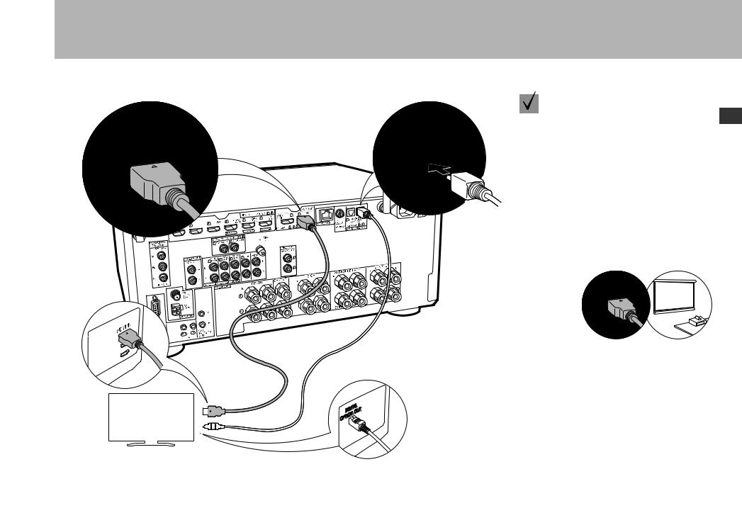
if you have: |
En |
Non-ARC TV |
This unit is connected between your TV and AV components. If you connect two or more AV components, you can select the video displayed on the TV and the audio output from this unit by changing the input selector. This describes the connections for a TV that does not support the ARC (Audio Return Channel) feature. By connecting with both an HDMI cable and a digital optical cable, you can not only output the video input to this unit to the TV, but you can also play the sound from the TV through this unit.
0 Connection with a digital optical cable is not necessary if you will watch TV through a device such as a cable set-top box (that is, not use a tuner built into the TV) that you have connected to the INPUT jack on this unit.
Another TV or projector can be connected to the HDMI OUT SUB jack. This jack does not support ARC. For details about how to output video from the HDMI OUT SUB jack (P22)
1 2
TV
1 HDMI cable, 2 Digital optical cable
13

> Before start > Hookup > Setup > Playback > Part Names
Step4: Connect the AV Components
 if you have:
HDMI AV Components
This is an example of connection with an AV component that has an HDMI jack. With connection to an AV component that conforms with the CEC (Consumer Electronics Control) standard, you can use features such as the HDMI CEC feature that links with the input selector, and the HDMI Standby Through feature which allows you to play video and audio from AV components on the TV even when this unit is in standby mode.
0 To play 4K or 1080p video, use a high speed HDMI cable. Further, to enjoy HDCP2.2 compatible video, connect to the HDMI IN1 to IN3 jacks.
Setup
0 HDMI setup (P21) is required to use the HDMI CEC and HDMI Standby Through features. Make settings after all connections are complete.
0 To enjoy digital surround sound including Dolby Digital, audio output should be set to "Bitstream output" on the connected Blu-ray Disc player or other device.
1
You can connect a device such as a video camera to the AUX
INPUT HDMI jack on the front panel.
BD/DVD
GAME |
Streaming media |
Cable/Satellite set-top |
player |
box |
1 HDMI cable
14
> Before start > Hookup > Setup > Playback
3 OR 2
1
BD/DVD
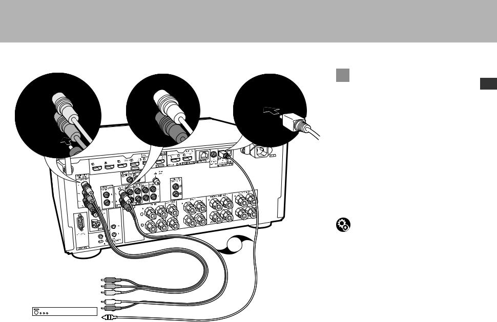
1 Component video cable, 2 Digital optical cable, 3 Analog audio cable
> Part Names
 if you have:
Non-HDMI AV Components En
This is an example of connection with an AV component that does not have an HDMI jack. Make the connections to the AV component to match the jacks it has. When video input connection is to the BD/DVD jack, the audio input connection should also be to the BD/DVD jacks, and so on, so that you connect the video input jacks to the jacks with the same name as the audio input jacks. Note that video signals input to the VIDEO IN jack or the COMPONENT VIDEO IN jacks will be converted to HDMI video signals and then output from the HDMI OUT jack.
0To enjoy digital surround playback in formats such as Dolby Digital, you need to make a connection for audio signals with a digital coaxial cable or digital optical cable.
0It is possible to change assignment of the input jacks you see in the illustration at left, so you can also connect to any jack other than BD/DVD. For details, see the Advanced Manual.
Setup
0 The COMPONENT VIDEO IN jacks are compatible only with 480i or 576i resolution. When you input video signals to the COMPONENT VIDEO IN jacks, set the output resolution of the
player to 480i or 576i. Select interlace if there is no option for 480i, etc. If your player does not support 480i or 576i output, use the VIDEO IN jack.
0 To enjoy digital surround sound including Dolby Digital, audio output should be set to "Bitstream output" on the connected Blu-ray Disc Player or other device.
15

> Before start > Hookup > Setup > Playback > Part Names
 if you have:
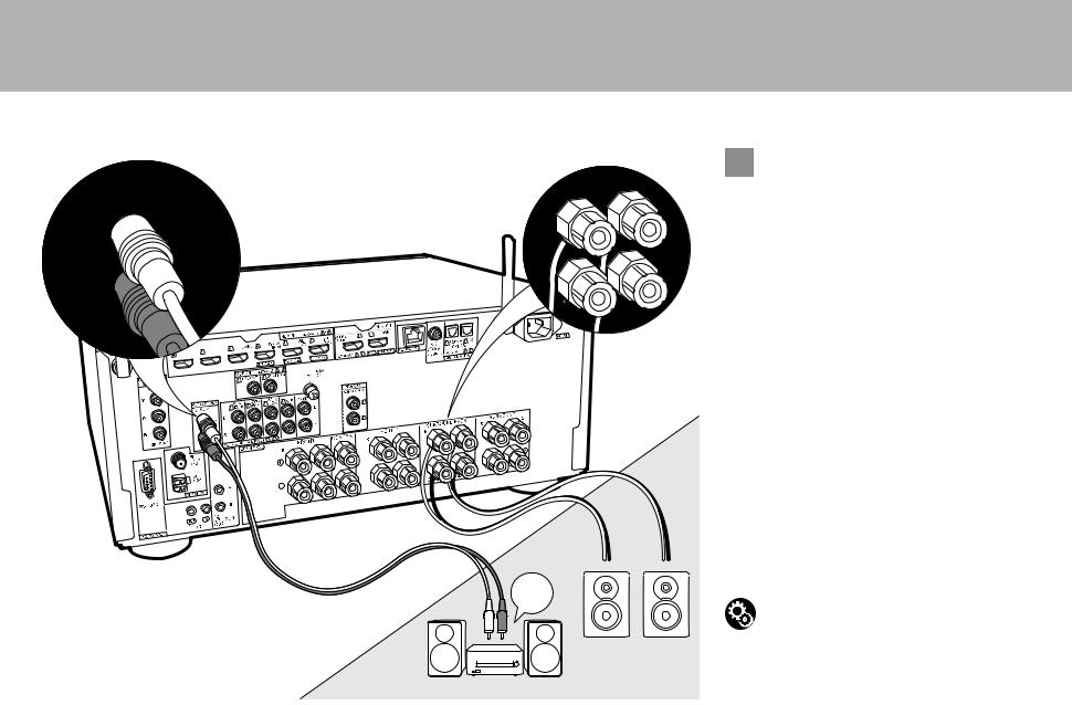
Audio Components
Example of a connection with an audio component. Connect a CD player using a digital coaxial cable or analog audio cable. You can also connect a turntable that has an MM-type cartridge to the PHONO jack.
0 If the turntable has a built-in audio equalizer, connect it to an AUDIO IN jack other than the PHONO jack. Further, if the turntable uses an MC type cartridge, install an audio equalizer compatible with the MC type cartridge between the unit and the turntable, then connect to any AUDIO IN jack other than the PHONO jack.
If the turntable has a ground wire, connect it to the SIGNAL GND terminal of this unit.
1
OR 2
CD |
Turntable |
1 Digital coaxial cable, 2 Analog audio cable
16

> Before start > Hookup > Setup > Playback > Part Names
Step5: Multi-zone Connection
MAIN ROOM
if you connect: |
En |
ZONE 2 TV |
You can enjoy content from a Blu-ray Disc player on a TV equipped with an HDMI input jack in the separate room (ZONE 2) by playing a Blu-ray Disc player in the main room (where this unit is located), or play the content from another AV component. Only the video from devices connected to the HDMI IN1 to IN3 jacks can be played on the TV in the separate room.
Setup
0Settings are required in Initial Setup, "4. Multi Zone Setup" (P21) to enjoy this feature.
0The audio from externally connected AV components can only be played in ZONE 2 when the audio is analog or 2ch PCM audio. It may also be necessary to convert the audio output of the AV component to PCM output.
ZONE2
1
TV
1 HDMI cable
17
> Before start > Hookup > Setup > Playback > Part Names
MAIN ROOM
ZONE2
2
1
LINE
IN
ZONE SPEAKER
ZONE2 PRE/LINE OUT
1 Analog audio cable, 2 Speaker cable
 ZONE 2 PRE/LINE OUT / ZONE SPEAKER
You can enjoy audio in the separate room by, for example, playing a Blu-ray Disc player in the main room (where this unit is located) and listening to internet radio in the separate room (ZONE 2).
Connections with an AV component
Connect with HDMI IN 1 to 3 if you want to output an external AV component to ZONE 2. If the AV component doesn't have an HDMI jack, connect using a digital optical cable, digital coaxial cable, or analog audio cable.
ZONE 2 PRE/LINE OUT
It is possible to play 2 ch source in a separate room while 7.1 ch source is being played in the main room. Connect the ZONE 2 PRE/LINE OUT jacks of the unit and the LINE IN jacks of the pre-main amplifier or the power amplifier in a separate room with an analog audio cable.
ZONE SPEAKER
It is possible to connect speakers in a separate room and play 2 ch sources.
0During ZONE 2 playback, no sound is heard from the surround back speakers or the height speakers and a maximum of 5.1 channel playback is possible in the main room. Listening modes such as the Dolby Atmos modes cannot be selected.
0Note that sound is not output from Speaker B when Zone Speaker is used.
Setup
0Settings are required in Initial Setup, "4. Multi Zone Setup" (P21) to enjoy this feature.
0The audio from externally connected AV components can only be played in ZONE 2 when the audio is analog or 2ch PCM audio. If you have connected to this unit with an HDMI cable or digital optical/coaxial cable, may be necessary to convert the audio output of the AV component to PCM output.
18
> Before start > Hookup > Setup > Playback
Step6: Connect Other Cables
(North American |
(European and |
models) |
Asian models) |


 2
2


3
1


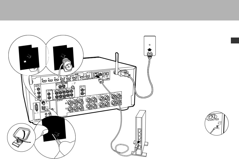
1 AM loop antenna, 2 Indoor FM antenna, 3 Ethernet cable, 4 Power cord
> Part Names
Antenna Hookup
Move the antenna around while playing the radio to find
the position with the best reception. Use a thumb tack or En similar to attach the indoor FM antenna to a wall.
Network Hookup
Connect this unit to the network using wired LAN or Wi-Fi (wireless LAN). You can enjoy network features such as internet radio, Music Server, and AirPlay by connecting the unit to the network.
If you connect by wired LAN, connect with an Ethernet cable to the NETWORK port as shown in the illustration. To connect by Wi-Fi, then after selecting "Wireless" in "3. Network Connection" (P21) in Initial Setup, select the desired setting method and follow the onscreen instructions to configure the connection.
Power Cord Hookup
4 This unit includes removable power cords. Connect the power cord to the power outlet after completing all other connections. Connect the power cord to AC IN of the unit and then connect to the outlet. Always disconnect the outlet side first when disconnecting the power cord.
You can find the voltage selector switch on the rear panel of multi-voltage models. Please set it to the correct voltage for your country or region.
Before changing the voltage, disconnect the power cord. Use a medium size screwdriver to change the voltage switch.
19
> Before start > Hookup > Setup > Playback > Part Names
Step7: Power On & Initial Setup
Initial Setup starts automatically
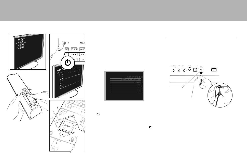
Once all connections are complete, change the TV's input to the input for this unit, inset batteries in the remote controller, and press Í to turn the power on. When you turn the unit on for the first time, Initial Setup is automatically shown on the TV to enable you to make settings required for startup using simple operations following onscreen guidance.
These instructions will guide you through some items that you need to check beforehand. Read beforehand so the setup goes smoothly.
Initial Setup
Language Select
 English
Deutsch
Français
Español
Italiano
Nederlands
Svenska
a |
Operation |
|
b |
Select the item with the cursors of the remote controller |
|
|
and press ENTER (a). To return to the previous screen, |
|
|
press |
(b). |
To redo the Initial Setup |
|
If you terminate the procedure on the way or want to |
|
change a setting made during Initial Setup, press |
on |
the remote controller, select "System Setup" – |
|
"Miscellaneous" – "Initial Setup" from Home, and press ENTER.
1. Full Auto MCACC
Place the supplied speaker setup microphone in the listening position, measure the test tones emitted by the speakers, then the unit automatically sets the optimum volume level for each speaker, the crossover frequencies, and the distance from the listening position. This also enables correction of distortion caused by the acoustic environment of the room.
MCACC
SETUP MIC
0When putting the speaker setup microphone on a tripod, refer to the illustration when putting it in place.
0The subwoofer sound may not be detected since it is extremely low frequencies. Set the subwoofer volume to more than halfway.
0Calibration takes several minutes to be completed. The speakers emit the test tone at high volume during measurement, so be careful of your surroundings. Keep the room as quiet as possible during measurement. If the measurement is interrupted, turn off the household appliances.
20
> Before start > Hookup > Setup > Playback > Part Names
2. Source Connection
Check that each input source is connected correctly. Follow the guidance, select the input you want to confirm, start play of the selected player, and confirm that the images appear on the TV and that sound is played.
3. Network Connection
Set up Wi-Fi connection with an access point such as a wireless LAN router. There are the following two methods of connecting by Wi-Fi:
"Scan Networks": Search for an access point from this unit. Find out the SSID of the access point beforehand.
"Use iOS Device (iOS7 or later)": Share the iOS device's Wi-Fi settings with this unit.
If you select "Scan Networks", there are a further two choices of connection method. Check the following.
0"Enter Password": Enter the password (or key) of the access point to connect.
0"Push Button": If the access point has an automatic connection button, you can connect without entering a password.
0If the SSID of the access point is not displayed, then in the screen listing the SSIDs, select "Other..." with the cursor on the remote controller and press ENTER, then follow the onscreen instructions.
Keyboard input
Wi-Fi Setup
SSID
|
|
|
|
|
|
|
a b c d e |
f |
g h |
i j k l |
m |
||
|
|
|
||||
n o p q r s t u v w x y |
z |
|||||
1 2 3 4 5 |
6 7 8 |
9 0 - ^ |
\ |
|
||
, . / ; : |
@ |
[ ] |
̺ |
|
|
|
|
A/a |
|
|
OK |
|
|
When finished, select the "OK" key. |
|
|
|
|||
|
|
|
|
All Erase |
A/a |
|
To switch between upper and lower case, select "A/a" on the screen and press ENTER. To select whether to mask the password with " " or display it in plain text, press +Fav on the remote controller. Press CLEAR to delete all the input characters.
0A confirmation screen asking you to agree to the privacy policy is displayed during network setting. Select "Yes" and press ENTER to indicate agreement.
4. Multi Zone Setup
Make these settings to enjoy video and audio in a room other than the main room (ZONE 2).
Select "Using AV Receiver" when connecting speakers in the separate room. Select "with External Premain Amplifier" when connecting a pre-main amplifier in the separate room. Select "with External Power Amplifier" when connecting a power amplifier.
If you are going to be connecting a TV in the separate room (ZONE 2), then when "Would you be using TV in 2nd room?" is displayed, select "Yes".
5. Audio Return Channel
If you have connected a TV that supports ARC, select "Yes". This unit's ARC setting turns on and you can listen to the TV's audio through this unit.
0If you select "Yes", the HDMI CEC function is enabled and power consumption increases during standby.
HDMI Setup
HDMI CEC
Make this setting to enable the control feature for devices complying with the CEC standard. This is set to on En automatically if you have selected "Yes" in "5. Audio Return Channel" in the Initial Setup.
Press the  button on the remote controller to set "System Setup" – "Hardware" – "HDMI" – "HDMI CEC" to "On" on the TV screen. Also enable the CEC control feature on the CEC device you have connected.
HDMI
HDMI CEC |
On |
HDMI Standby Through |
Auto(Eco) |
Audio TV Out |
Auto |
Audio Return Channel |
Auto |
Auto Delay |
On |
HDMI Standby Through
Even if this unit is in standby, the input signals from AV components are transmitted to the TV.
0"Auto" / "Auto (Eco)": Select one of these settings when connected AV components comply with the CEC standard. Irrespective of the input selector selected immediately before switching the unit to standby, you can transmit the input signals from AV components to the TV. Select "Auto (Eco)" if the TV is also CEC-compliant. You can reduce power consumption in standby mode.
0Input selector names for "BD/DVD", etc.: You can transmit the input signals from the set input selector to the TV. It can be selected when "HDMI CEC" is set to "Off".
0"Last": You can transfer the input signals of the input
selector selected immediately prior to the unit being switched to standby. It can be selected when "HDMI CEC" is set to "Off".
To exit the settings, press  .
.
21
 Loading...