


ORDER NO.
RRV2001
FILE-TYPE CD PLAYER
PD-F1007
THIS MANUAL IS APPLICABLE TO THE FOLLOWING MODEL(S) AND TYPE(S).
Type |
Model |
Power Requirement |
Remarks |
|
|
||||
PD-F1007 |
||||
|
|
|
||
|
|
|
|
|
KU |
|
AC120V |
|
|
|
|
|
|
CONTENTS
1. SAFETY INFORMATION .................................... |
2 |
7. GENERAL INFORMATION .............................. |
44 |
2. EXPLODED VIEWS AND PARTS LIST ............. |
3 |
7.1 PARTS ....................................................... |
44 |
3. SCHEMATIC DIAGRAM ................................... |
10 |
7.1.1 IC ....................................................... |
44 |
4. PCB CONNECTION DIAGRAM ....................... |
22 |
7.1.2 DISPLAY ........................................... |
47 |
5. PCB PARTS LIST ............................................. |
30 |
7.2 DIAGNOSIS ................................................ |
48 |
6. ADJUSTMENT .................................................. |
34 |
7.2.1 DISASSEMBLY ................................. |
48 |
|
|
7.2.2 ERROR CCHECK DISPLAY ............. |
51 |
|
|
7.2.3 EXPLANATION OF DISC |
|
|
|
DETECTION ...................................... |
52 |
|
|
7.3 BLOCK DIAGRAM ...................................... |
54 |
|
|
8. PANEL FACILITIES AND SPECIFICATIONS |
|
|
|
....................................................... |
55 |
PIONEER ELECTRONIC CORPORATION 4-1, Meguro 1-Chome, Meguro-ku, Tokyo 153-8654, Japan PIONEER ELECTRONICS SERVICE, INC. P.O. Box 1760, Long Beach, CA 90801-1760, U.S.A.
PIONEER ELECTRONIC (EUROPE) N.V. Haven 1087, Keetberglaan 1, 9120 Melsele, Belgium
PIONEER ELECTRONICS ASIACENTRE PTE. LTD. 501 Orchard Road, #10-00 Wheelock Place, Singapore 238880
 PIONEER ELECTRONIC CORPORATION 1998
T–DZE AUG. 1998 Printed in Japan
PD-F1007
1. SAFETY INFORMATION
This service manual is intended for qualified service technicians; it is not meant for the casual do-it-yourselfer. Qualified technicians have the necessary test equipment and tools, and have been trained to properly and safely repair complex products such as those covered by this manual.
Improperly performed repairs can adversely affect the safety and reliability of the product and may void the warranty. If you are not qualified to perform the repair of this product properly and safely, you should not risk trying to do so and refer the repair to a qualified service technician.
WARNING
This product contains lead in solder and certain electrical parts contain chemicals which are known to the state of California to
cause cancer, birth defects or other reproductive harm.
Health & Safety Code Section 25249.6 – Proposition 65
NOTICE
(FOR CANADIAN MODEL ONLY)
Fuse symbols 
 (fast operating fuse) and/or
  (slow operating fuse) on PCB indicate that replacement parts must be of identical designation.
REMARQUE
(POUR MODÈLE CANADIEN SEULEMENT)
Les symboles de fusible 


 (fusible de type rapide) et/ou

 (fusible de type lent) sur CCI indiquent que les pièces de remplacement doivent avoir la même désignation.
(FOR USA MODEL ONLY)
1. SAFETY PRECAUTIONS
The following check should be performed for the continued protection of the customer and service technician.
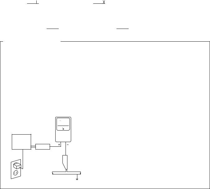
LEAKAGE CURRENT CHECK
Measure leakage current to a known earth ground (water pipe, conduit, etc.) by connecting a leakage current tester such as Simpson Model 229 - 2 or equivalent between the earth ground and all exposed metal parts of the appliance (input/output terminals, screwheads, metal overlays, control shaft, etc.). Plug the AC line cord of the appliance directly into a 120V AC 60 Hz outlet and turn the AC power switch on. Any current measured must not exceed 0.5 mA.
|
Reading should |
|
not be above |
|
Leakage 0.5 mA |
Device |
current |
tester |
|
under |
|
test |
|
|
Test all exposed |
|
metal surfaces |
Also test with plug reversed
(Using AC adapter plug as required)
Earth ground
AC Leakage Test
ANY MEASUREMENTS NOT WITHIN THE LIMITS OUTLINED ABOVE ARE INDICATIVE OF A POTENTIAL SHOCK HAZARD AND MUST BE CORRECTED BEFORE RETURNING THE APPLIANCE TO THE CUSTOMER.
2. PRODUCT SAFETY NOTICE
Many electrical and mechanical parts in the appliance have special safety related characteristics. These are often not evident from visual inspection nor the protection afforded by them necessarily can be obtained by using replacement components rated for voltage, wattage , etc. Replacement parts which have these special safety characteristics are identified in this Service Manual.
Electrical components having such features are identified by marking with a  on the schematics and on the parts list in this Service Manual.
The use of a substitute replacement component which does not have the same safety characteristics as the PIONEER recommended replacement one, shown in the parts list in this Service Manual, may create shock, fire, or other hazards.
Product Safety is continuously under review and new instructions are issued from time to time. For the latest information, always consult the current PIONEER Service Manual. A subscription to, or additional copies of, PIONEER Service Manual may be obtained at a nominal charge from PIONEER.
2
PD-F1007
2. EXPLODED VIEWS AND PARTS LIST
NOTES : |
Parts marked by “ NSP ” are generally unavailable because they are not in our Master Spare Parts List. |
|
|
The |
mark found on some component parts indicates the importance of the safety factor of the part. |
|
Therefore, when replacing, be sure to use parts of identical designation. |
|
|
Screw adjacent to mark on the product are used for disassembly. |
|
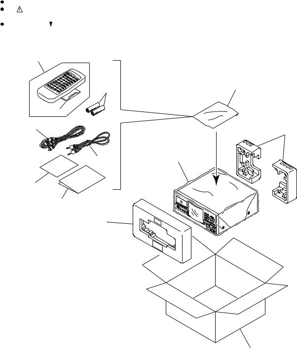
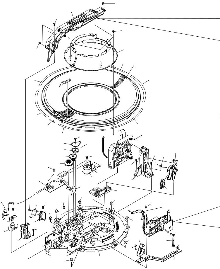
2.1 PACKING
7
9 |
5 |
|
8
11
2
10 |
4 |
12
6
1
PACKING PARTS LIST
Mark |
No. |
|
Description |
Part No. |
|||
|
|
|
|
|
|
|
|
|
|
|
|
|
|
|
|
|
|
1 |
|
Styrol Protector F |
PHA1325 |
||
|
|
2 |
|
Styrol Protector R |
PHA1326 |
||
|
|
3 |
|
Packing Case |
PHG2316 |
||
|
|
4 |
|
Packing Sheet |
RHC1023 |
||
|
|
5 |
|
Polyethylene Bag |
Z21–038 |
||
|
|
|
(0.03 × 230 × 340) |
|
|
|
|
|
|
6 |
|
Operating Instructions (English) |
PRB1271 |
||
|
|
7 |
|
Remote Control Unit |
PWW1139 |
||
|
|
|
|
(CD-PD094) |
3 |
||
|
|
8 |
|
Battery Cover |
|||
|
|
|
AZA7204 |
||||
NSP |
9 |
|
Dry Cell Batteries (R6P, AA) |
VEM–013 |
|||
|
|
10 |
|
Control Cable (L=1 m) |
PDE1247 |
||
|
|
11 |
|
Audio Cable (L=1 m) |
PDE1248 |
||
NSP |
12 |
|
Warranty Card |
ARY7023 |
|||
3
PD-F1007
8
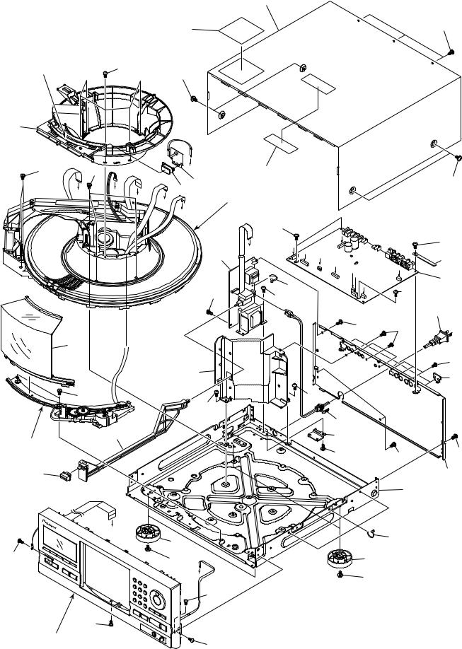
2.2 EXTERIOR (1/2)
19 |
20 |
|
2 |
22 |
|
|
|
21 |
14
(1/2)
6 |
6 |
F |
|
18 |
|
|
|
|
|||
|
|
3 |
|
|
|
C |
D |
15 |
|
|
|
E |
Refer to " 2.3 EXTERIOR (2/2)". |
|
|||
|
|
G |
|
|
|
|
|
H |
|
|
|
|
|
|
|
22 |
|
|
|
|
|
A |
I |
|
|
|
I |
|
|
|
|
2 |
C D |
E |
|
|
|
|
|
|
|
|
|
|
|
|
F G |
|
|
20 |
|
23 |
H |
|
|
|
20 |
||
|
|
|
|
|
|
|
|
|
|
|
20 |
17 |
|
|
|
|
|
|
|
11 (1/2) |
|
|
|
6 |
|
|
|
20 |
|
|
|
20 |
|
|
|
|
|
|
|
|
4 |
|
12 |
|
|
|
11 (2/2) |
Hood Base Assy
20
16
A
|
10 |
|
20 |
20 |
10 |
|
B |
20 |
|
20 |
|
20 |
|
|
Refer to " 2.5 FRONT PANEL |
20 |
|
ASSY SECTION". |
||
|
21
22
13
B
1
22
5
20
20
14
(2/2)
20
20
9
7
23
4
PD-F1007
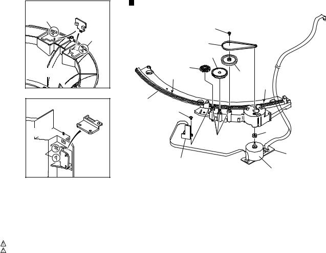
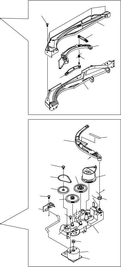
No. 14: Center Pole |
Hood Base Assy Section |
||
|
|
||
Cut |
14 (2/2) |
|
|
|
|
33 |
|
|
Cut |
26 |
|
|
|
||
|
|
28 |
|
14 (1/2) |
30 |
|
|
2 |
31 |
||
|
|||
|
|
2 |
|
No. 11: Trans Cover |
29 |
|
|
33 |
|
||
|
|
||
11(1/2) |
|
27 |
|
|
11(2/2) |
1 |
|
Cut |
|
24 |
|
|
25 |
|
|
|
|
32 |
|
EXTERIOR (1/2) PARTS LIST
Mark |
No. |
|
Description |
|
Part No. |
|
|
|
|
|
|
|
|
|
|
1 |
|
MAIN BOARD ASSY |
|
PWZ3822 |
|
|
|
|
|||
|
|
2 |
|
POWER BOARD ASSY |
|
PWZ3852 |
NSP |
3 |
|
LED BOARD ASSY |
|
PWZ3867 |
|
|
|
4 |
|
Strain Relief |
|
CM–22C |
|
|
5 |
|
AC Power Cord |
|
VDG1057 |
|
|
6 |
|
Screw C |
|
PBA1106 |
NSP |
7 |
|
Under Base |
|
PNA2421 |
|
|
|
8 |
|
Bonnet Case |
|
PYY1255 |
|
|
9 |
|
Rear Base |
|
PNA2424 |
|
|
10 |
|
Insulator |
|
PNW2766 |
|
|
11 |
|
Trans Cover |
|
PNW2802 |
|
|
12 |
|
Joint |
|
PNW2805 |
|
|
13 |
|
Cord Clamper |
|
RNH–184 |
|
|
14 |
|
Center Pole |
|
PNW2792 |
|
|
15 |
|
CR Lens |
|
PNW2816 |
|
|
16 |
|
POWER Button |
|
PAC1884 |
|
|
17 |
|
Hood |
|
PNW2793 |
|
|
18 |
|
65 Label |
|
ORW1069 |
|
|
19 |
|
Caution Label |
|
PRW1517 |
|
|
20 |
|
Screw |
|
BBZ30P080FZK |
|
|
21 |
|
Screw |
|
FBT40P080FZK |
|
|
22 |
|
Screw |
|
IBZ30P080FMC |
|
|
23 |
|
Binder |
|
ZCA–SKB90BK |
|
|
2 |
|
Ha Narl PN955R (for service) |
|
GEM1016 |
Mark |
|
No. |
|
Description |
|
Part No. |
|
|
|
|
|
|
|
|
|
|
|
|
|
|
|
|
|
|
Hood Base Assy Section |
|
|
||||
|
|
|
|||||
NSP |
24 |
|
DOOR MOTOR BOARD ASSY |
|
PWZ3863 |
||
NSP |
25 |
|
DOOR SW BOARD ASSY |
|
PWZ3865 |
||
|
|
26 |
|
Belt |
|
PEB1300 |
|
|
|
27 |
|
Motor Pulley |
|
PNW1634 |
|
|
|
28 |
|
Gear |
|
PNW2641 |
|
|
|
29 |
|
Hood Base |
|
PNW2791 |
|
|
|
30 |
|
Gear M1 |
|
PNW2800 |
|
|
|
31 |
|
Gear Pulley |
|
VNL1662 |
|
|
|
32 |
|
Slider Motor |
|
VXM1033 |
|
|
|
33 |
|
Screw |
|
IPZ20P080FMC |
|
|
|
|
1 |
|
Froil 397 (for service) |
|
GYA1001 |
|
|
|
2 |
|
Ha Narl PN955R (for service) |
|
GEM1016 |
5
PD-F1007
2.3 EXTERIOR (2/2)
11
44
44
45
52
1
7 |
52 |
52 |
|
|
6 |
50
32
41
50
38
39
52
53
52
52

 B
B
40
44 33
44
46
|
|
|
|
44 |
|
44 |
51 |
A |
|
Refer to " 2.4 FLOAT BASE |
|
|
ASSY SECTION". |
||||
|
|
||||
9 |
|
|
|
|
|
10 |
|
|
|
|
21 |
|
|
|
|
52 |
|
35 |
|
31 |
|
8 |
|
|
|
|
|||
|
|
|
|
|
|
36 |
|
|
52 |
|
|
|
|
|
|
|
|
|
|
2 |
|
|
|
|
|
43 |
20 |
|
|
|
|
|
|
|
|
|
5 |
|
|
|
|
|
|
19 |
|
|
15 |
|
32 |
|
|
|
|
42 |
C |
32 |
|
|
|
1 |
2 |
|
52 |
|
|
32 |
|
|
|||
1 |
B |
|
|
||
|
|
|
|
||
1 |
|
A |
|
|
|
|
|
|
32 |
|
|
|
1 |
|
|
|
|
|
|
|
|
|
|
|
|
|
1 |
|
|
|
C |
|
32 |
37 |
28 |
|
|
|
|
||
1 |
|
|
|
|
|
|
1 |
|
|
|
|
|
|
47 |
|
|
|
|
1 |
|
|
|
|
32 |
|
34 |
|
|
30 |
6
52
27
23
25
12
24
26
 2 [ Apply the Guide R (No. 27) also at the same position.]
14
22
Note) Tightening Torque: 2 kg·cm |
b |
|
|
51 |
|
|
17 |
29 |
|
9 |
|
|
10 |
b |
49 |
|
|
|
16 |
13 |
4 |
a |
|
|
|
|
|
48 |
|
|
a |
|
|
1 |
18 |
|
|
31 |
43
3
PD-F1007
EXTERIOR (2/2) PARTS LIST
Mark |
No. |
|
Description |
|
Part No. |
|
|
|
|
|
|
|
|
|
|
|
|
|
|
|
NSP |
1 |
|
SENSOR BOARD ASSY |
|
PWZ3781 |
|
NSP |
2 |
|
SELECT BOARD ASSY |
|
PWZ3785 |
|
NSP |
3 |
|
LOADING BOARD ASSY |
|
PWZ3788 |
|
NSP |
4 |
|
LOADING SW BOARD ASSY |
|
PWZ3790 |
|
NSP |
5 |
|
RADIATE BOARD ASSY |
|
PWZ3791 |
|
NSP |
6 |
|
RECEIVE BOARD ASSY |
|
PWZ3792 |
|
|
|
7 |
|
VOLUME BOARD ASSY |
|
PWZ3866 |
|
|
8 |
|
Clamp Spring |
|
ABH7107 |
|
|
9 |
|
Loading Belt |
|
AEB7029 |
|
|
10 |
|
Gear Pulley B |
|
ANW7062 |
|
|
11 |
|
Roller B |
|
ANW7075 |
|
|
12 |
|
Arm Spring |
|
PBH1225 |
|
|
13 |
|
D Arm Spring |
|
PBH1226 |
|
|
14 |
|
Sheet |
|
PED1028 |
|
|
15 |
|
Clamper |
|
PNW2743 |
|
|
16 |
|
Gear 1 |
|
PNW2819 |
|
|
17 |
|
Gear 2 |
|
PNW2820 |
|
|
18 |
|
Gear Holder |
|
PNW2822 |
|
|
19 |
|
Slider Cam |
|
PNW2823 |
|
|
20 |
|
Clamp Support |
|
PNW2826 |
|
|
21 |
|
Clamp Holder |
|
PNW2827 |
|
|
22 |
|
Drive Arm |
|
PNW2829 |
|
|
23 |
|
Link |
|
PNW2830 |
NSP |
24 |
|
L Slider |
|
PNW2831 |
|
NSP |
25 |
|
L Arm |
|
PNW2832 |
|
|
|
26 |
|
Guide L |
|
PNW2833 |
|
|
27 |
|
Guide R |
|
PNW2834 |
|
|
28 |
|
Link L |
|
PNW2844 |
|
|
29 |
|
Drive Cam |
|
PNW2873 |
|
|
30 |
|
Lock Plate |
|
PNA2438 |
|
|
31 |
|
Motor Pulley |
|
PNW1634 |
|
|
32 |
|
Roller |
|
PNW2647 |
|
|
33 |
|
Disc Rack |
|
PNW2790 |
|
|
34 |
|
Rack Base |
|
PNW2835 |
|
|
35 |
|
ST Gear 0.6 |
|
PNW2836 |
|
|
36 |
|
ST Gear 1.0 |
|
PNW2837 |
|
|
37 |
|
Disc Divider |
|
PNW2838 |
|
|
38 |
|
Guide Support L |
|
PNW2839 |
|
|
39 |
|
Guide Support R |
|
PNW2840 |
|
|
40 |
|
Disc Guard |
|
PNW2841 |
|
|
41 |
|
Sensor Stay |
|
PNW2842 |
|
|
42 |
|
Guide Roller |
|
PNW2843 |
|
|
43 |
|
Slider Motor |
|
VXM1033 |
|
|
44 |
|
Rack Label |
|
PAM1770 |
|
|
45 |
|
S Label |
|
PAM1771 |
|
|
46 |
|
+1 Label |
|
PRW1507 |
|
|
47 |
|
Screw |
|
BBZ30P080FZK |
|
|
48 |
|
Screw |
|
BMZ26P040FZK |
|
|
49 |
|
Screw |
|
BPZ26P060FMC |
|
|
50 |
|
Screw |
|
BPZ30P100FCU |
|
|
51 |
|
Screw |
|
IPZ20P080FMC |
|
|
52 |
|
Screw |
|
PPZ30P080FMC |
|
|
53 |
|
Arm Assy |
|
PXA1615 |
|
|
1 |
|
Froil 397 (for service) |
|
GYA1001 |
|
|
2 |
|
Ha Narl PN955R (for service) |
|
GEM1016 |
7
PD-F1007
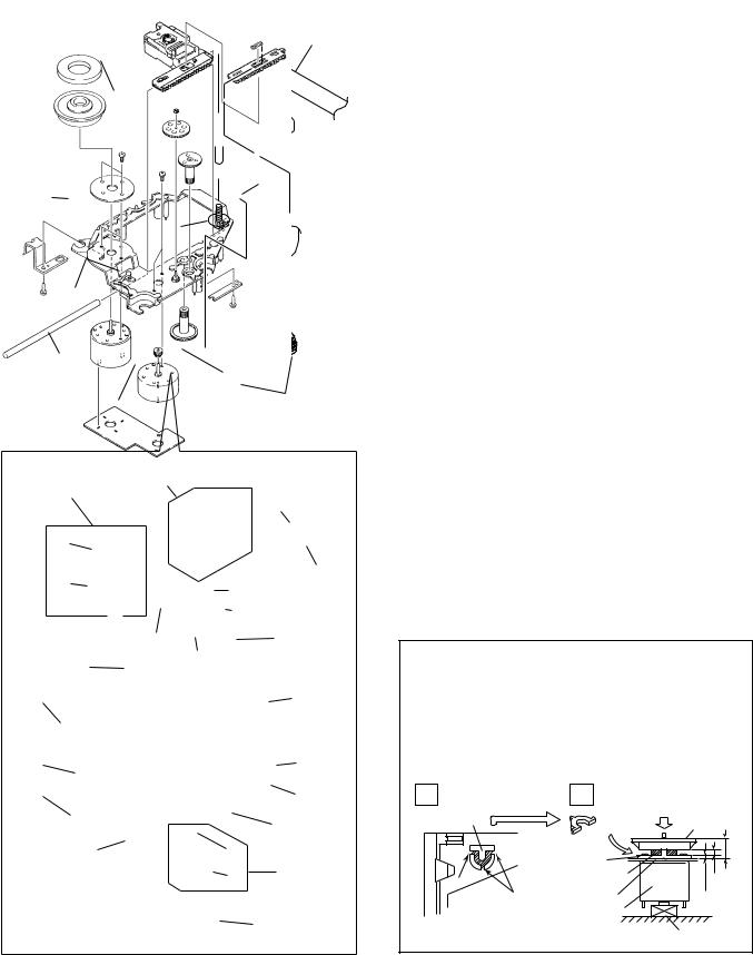
2.4 FLOAT BASE ASSY SECTION
30
26
28
33
27
29
32
29
31
5
10
|
|
|
24 |
17 |
|
|
|
19 |
|
|
25 |
|
16 |
|
|
|
15 |
|
|
|
3 |
|
|
|
|
|
|
|
|
14 |
2 |
|
|
|
|
18 |
|
|
|
20 |
|
|
4 |
23 |
|
|
21 |
12 |
|
|
22 |
|
|
|
|
|
|
|
1 |
6 |
|
8 |
|
|
|
9 |
7 |
|
|
|
11 |
FLOAT BASE ASSY SECTION PARTS LIST
Mark |
No. |
|
Description |
|
Part No. |
|
|
|
|
|
|
|
|
|
|
1 |
|
Gear 1 |
|
PNW2052 |
|
|
|
|
|||
|
|
2 |
|
Gear 2 |
|
PNW2053 |
|
|
3 |
|
Gear 3 |
|
PNW2054 |
|
|
4 |
|
Carriage Base |
|
PNW2699 |
|
|
5 |
|
Pickup Assy - S |
|
PEA1335 |
|
|
6 |
|
D.C. Motor Assy (SPINDLE) |
|
PEA1235 |
|
|
7 |
|
Carriage DC Motor Assy |
|
PEA1246 |
|
|
8 |
|
Pinion Gear |
|
PNW2055 |
|
|
9 |
|
Carriage DC Motor/0.3W |
|
PXM1027 |
|
|
10 |
|
Disc Table Assy |
|
PEA1314 |
|
|
11 |
|
Mechanism Board Assy |
|
PWX1192 |
|
|
12 |
|
Guide Bar |
|
PLA1094 |
|
|
13 |
|
………… |
|
|
|
|
14 |
|
Screw |
|
JFZ17P025FZK |
|
|
15 |
|
Screw |
|
JFZ20P040FMC |
|
|
16 |
|
Washer |
|
WT12D032D025 |
|
|
17 |
|
Clamp Magnet |
|
PMF1014 |
|
|
18 |
|
Yoke M |
|
PNB1312 |
NSP |
19 |
|
Disc Table |
|
PNW2410 |
|
NSP |
20 |
|
Float Angle |
|
ANB7020 |
|
|
|
21 |
|
Gear Stopper |
|
PNB1303 |
|
|
22 |
|
Screw |
|
BPZ20P060FMC |
|
|
23 |
|
Screw |
|
BPZ26P100FMC |
|
|
24 |
|
PU Rack Spring |
|
ABH7077 |
|
|
25 |
|
Rack Holder |
|
PNW2056 |
|
|
26 |
|
Float Base |
|
PNW2828 |
|
|
27 |
|
Screw |
|
ABA7009 |
|
|
28 |
|
Float Spring |
|
ABH7049 |
|
|
29 |
|
Float Rubber |
|
AEB7028 |
|
|
30 |
|
16P F·F·C/30V |
|
PDD1185 |
NSP |
31 |
|
Servo Mechanism Assy GM |
|
PXA1591 |
|
|
|
32 |
|
Connector Assy (4P) |
|
RDE1043 |
|
|
33 |
|
Sheet |
|
PED1028 |
¦ How to Install the Disc Table
1 Use nipper or other tool to cut the three sections marked A in figure 1. Then remove the spacer
2While supporting the spindle motor shaft with the stopper, put spacer on top of the yoke M, and stick the disc table on top (takes about 9kg pressure). Detach the spacer.
1 |
|
2 |
(Pressure of about 9 kg) |
|
|
|
|
|
Spacer |
Spacer |
Disc Table |
|
|
||
|
|
|
6.9mm
|
Yoke M |
|
|
A |
Spacer Setting |
0.9mm |
|
Position |
|||
±0.05mm |
|||
A |
Carriage Base |
1.2mm |
Spindle Motor
Float Base
Stopper
8
PD-F1007
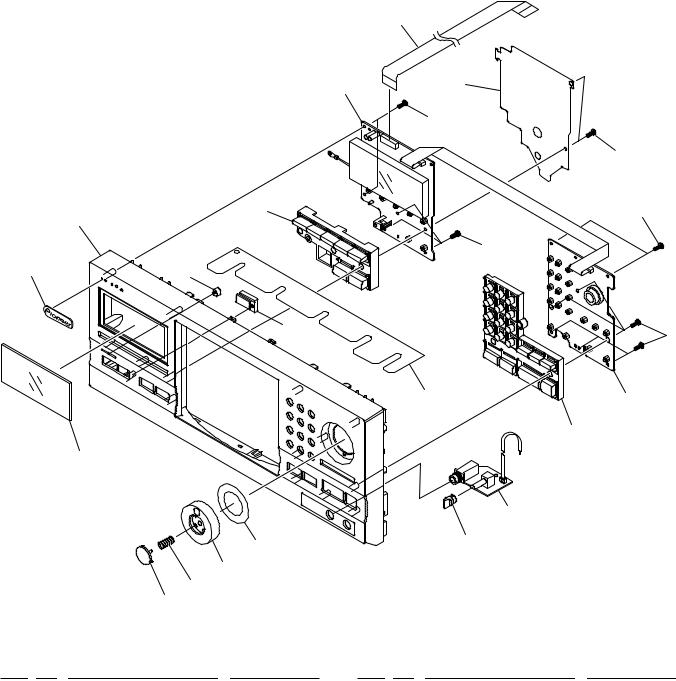
2.5 FRONT PANEL ASSY SECTION
4
1 |
14 |
|
|
|
19 |
19
5 |
19 |
16
19
9 |
15 |
|
17 |
19 |
|
|
|
|
|
|
13 |
2 |
|
|
|
|
|
|
|
|
|
|
|
|
|
6 |
|
|
10 |
|
|
|
|
|
|
|
|
|
|
3 |
|
|
|
12 |
|
18 |
|
|
|
|
|
|
|
|
|
|
|
7 |
|
|
|
|
|
11 |
|
|
|
|
|
|
8 |
|
|
|
|
FRONT PANEL ASSY SECTION PARTS LIST |
|
|
|
|||
Mark |
No. |
Description |
Part No. |
Mark No. |
Description |
Part No. |
|
1 |
DISPLAY BOARD ASSY |
PWZ3839 |
11 |
Enter Spring |
PBH1228 |
NSP |
2 |
FUNCTION BOARD ASY |
PWZ3847 |
12 |
Jog Sheet |
PEC1042 |
NSP |
3 |
HEADPHONE BOARD ASSY |
PWZ3860 |
13 |
FC Cover |
PNM1323 |
|
4 |
16P F·F·C/30V |
PDD1189 |
14 |
PCB Cover |
PNM1324 |
|
5 |
MODE Button |
PAC1880 |
15 |
LED Lens |
PNW2019 |
|
6 |
PLAY Button |
PAC1881 |
16 |
Operation Panel |
PNW2794 |
|
7 |
Jog Dial |
PAC1882 |
17 |
Sensor Lens |
PNW2804 |
|
8 |
ENTER Button |
PAC1883 |
18 |
Rotary Knob |
RAC1903 |
|
9 |
Name Plate |
PAM1776 |
19 |
Screw |
PPZ30P100FMC |
|
10 |
Display Window |
PAM1782 |
|
|
|
9
|
1 |
|
2 |
|
3 |
|
4 |
|
|
|
|
|
|
PD-F1007
3. SCHEMATIC DIAGRAM
Note : When ordering service parts, be sure to refer to "EXPLODED VIEWS and PARTS LIST" or "PCB PARTS LIST".
A
|
|
|
|
|
|
|
|
Large size |
|
|
|
A-a |
|
|
A-b |
|
|
|
|
|
|
|
|
SCH diagram |
||
|
|
|
A-c |
|
A-d |
|||
|
|
|
|
|
||||
|
|
|
|
|
|
|
|
|
|
|
|
|
|
|
|
|
|
|
|
|
|
|
|
|
|
|
A-a A-b |
Guide page |
B
Detailed page
A-a A-b
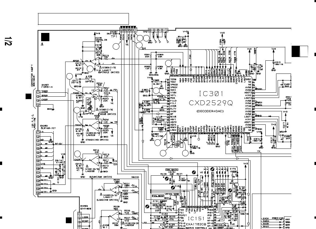
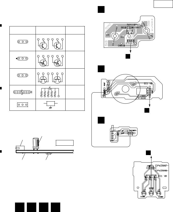
3.1MECHANISM BOARD, DOOR MOTOR BOARD, DOOR SW BOARD, LED BOARD and PICKUP ASSEMBLIES
SERVO MECHANISM ASSY (PXA1591)
SPINDLE
MOTOR
ASSY
PEA1235
SIGNAL ROUTE |
CARRIADGE |
|
(F) |
: FOCUS SERVO LOOP |
MOTOR |
|
||
(T) |
: TRACKING SERVO LOOP |
ASSY |
|
||
(C)
 : CARRIAGE SERVO LOOP
(S)
: SPINDLE DRIVE
PEA1246
|
|
|
|
|
|
|
|
|
|
|
|
|
|
C |
DOOR SW |
B |
DOOR MOTOR |
|
|
|
BOARD ASSY |
|
BOARD ASSY |
|
|
|
|
||
|
|
|
(PWZ3865) |
|
(PWZ3863) |
C
K
CN205
DOOR MOTOR
VXM1033
D LED BOARD ASSY (PWZ3867)
K
CN208
D
K
CN207
A MECHANISM BOARD ASSY (PWX1192)
PICKUP ASSY (PEA1335)
K
CN202
(T)
(T)
(F)
(F)
10
|
1 |
|
2 |
|
3 |
|
4 |
|
|
|
|
|
|
||||
|
|
|
|
|
|
1 |
|
2 |
|
3 |
|
4 |
|
|
|
|
|
|
PD-F1007
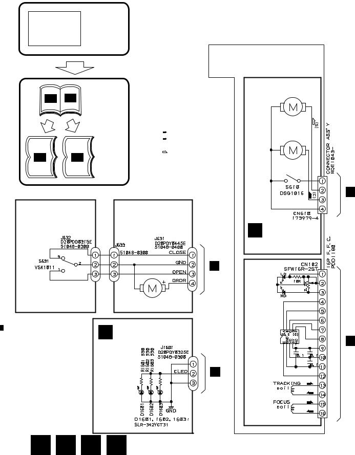
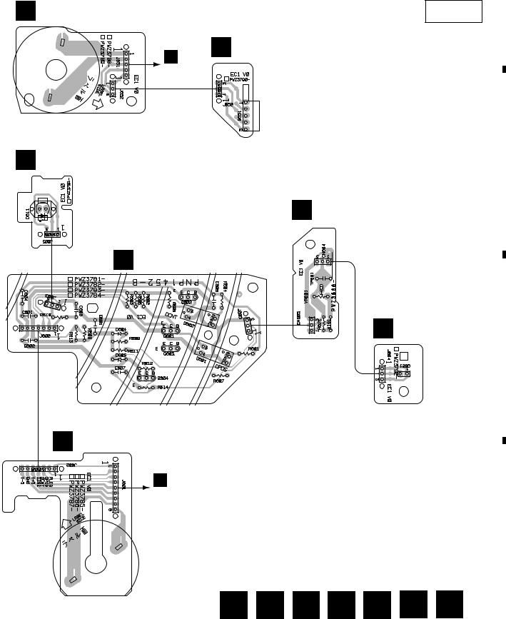
3.2LOADING SW, LOADING BOARD, SENSOR BOARD, RECIEVE BOARD, RADIATE BOARD and SELECT BOARD ASSEMBLIES
A
F LOADINGBOARD
ASSY (PWZ3788)
E LOADING SW ASSY (PWZ3790)
REAF SW
VSK1011
G SENSOR BOARD |
|
ASSY |
|
(PWZ3781) |
1.5k |
|
100k |
100k |
|
150
D20PDY0310E |
J605 |
|
K |
|
|
|
CN203 |
|
|
LOADING MOTOR |
|
B |
|
VXM1033 |
|
||
|
|
||
P |
VOLUME BOARD ASSY |
|
|
|
(PWZ3866) |
H |
RECIEVE |
22k |
|
||
|
|
|
BOARD |
VR601 |
|
ASSY |
|
|
|
|
|
CN605 |
CN604 |
|
(PWZ3792) |
|
|
||
52147–0310 ×2 J604 |
|
|
|
D20PDY0315E
I RADIATEBOARD
ASSY (PWZ3791)
C
K
CN204
SELECT MOTOR
VXM1033
J SELECTBOARD
ASSY (PWZ3785)
D
11
|
1 |
|
2 |
|
3 |
|
4 |
|
|
|
|
|
|
||||
|
|
|
|
|

|
1 |
|
2 |
|
3 |
|
4 |
|
|
|
|
|
|
PD-F1007
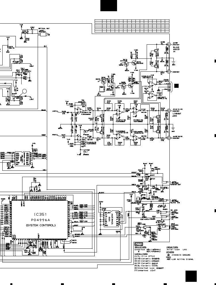
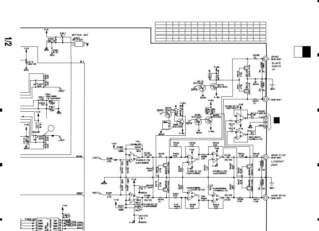
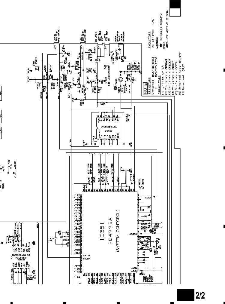
3.3 MAIN BOARD ASSY
K-a
CAUTION : FOR CONTINUED PROTECTION AGAINST RISK OF FIRE,
REPLACE ONLY WITH SAME TYPE NO. ICP-N10, MFD BY
ROHM CO., FOR IC35 AND IC36.
A |
|
|
|
|
|
|
|
|
|
|
|
MAIN |
|
|
|
2 23 |
|
|
|
|
|
K BOARD |
|
|
|
|
|
|
|
|
|
|
|
3 |
4 |
|
|
|
|
|
|
ASSY |
|
|
|
|
|
||
|
|
(PWZ3822) |
1.8V |
|
|
|
|
|
|
|
|
|
|
|
|
|
|
||
|
|
|
-0.7V |
|
(S) |
|
|
|
|
|
|
|
|
|
|
|
|
|
|
|
|
|
(S) |
|
|
|
|
|
|
|
|
|
|
1.8V |
(S) |
|
33 |
|
|
|
|
|
|
|
|
|
|
|
|
|
|
|
7 |
|
|
|
|
|
|
|
|
5 |
|
|
|
|
|
|
|
|
|
|
|
1.6V |
|
|
|
|
|
|
|
|
|
|
(F) |
53 |
|
|
|
A |
|
|
(F) |
|
|
|
|
|
|
|
|
0V |
|
|
|
|
|
|
|
CN610 |
|
|
|
1.6V |
|
|
|
|
|
|
|
|
6 |
|
|
|
|
|
|
|
|
|
|
1.6V |
|
|
|
|
|
|
|
|
|
|
(T) |
|
|
|
|
|
|
|
(T) |
|
|
|
|
|
|
|
|
|
0V |
|
|
|
|
|
|
B |
|
|
|
1.6V |
|
|
|
|
|
|
|
|
|
|
18 |
|
|
|
|
|
|
(F) |
|
|
|
|
|
|
|
ASSY |
|
(F) |
8 |
|
|
19 |
16 |
|
|
|
(F) |
1.7V |
|
|
|
||||
|
|
(F) |
|
|
|
|
|
|
|
PICUPto |
|
|
0.2V |
|
|
|
|
|
|
|
|
|
|
(C) |
|
(T) |
(T) |
(F) (F) (F) (F) |
|
|
|
(T) |
|
1.7V |
|
|
|
|
|
|
|
(T) |
|
|
|
0V |
|
|
|
|
|
|
0V |
|
(L) |
|
|
|
|
|
|
|
|
|
|
|
|
||
|
|
|
|
|
|
|
|
|
|
|
|
|
|
(L) |
|
(L) |
|
|
|
|
|
|
|
|
|
|
|
|
|
|
|
|
|
|
0V |
|
|
|
|
|
|
|
|
|
|
(SEL) |
|
|
|
|
|
|
|
|
|
(SEL) |
|
|
|
|
|
F |
|
(SEL) |
|
(F) |
|
|
|
|
|
J651 |
|
|
|
|
|
|
|
|
|
|
|
|
|
|
23 |
|
|
|
SIGNAL ROUTE |
|
|
|
|
|
|
|
|
C |
|
: AUDIO SIGNAL |
|
|
|
|
|
|
|
|
: EFM SIGNAL |
|
|
|
|
|
|
|
|
|
|
|
|
|
|
|
|
|
|
|
(F) |
: FOCUS SERVO LOOP |
|
|
|
(T) |
|
|
|
|
|
|
|
|
|
|
|
|
|
|
(T) |
: TRACKING SERVO LOOP |
|
|
|
|
|
|
|
|
|
|
|
|
|
|
|
|
|
|
(C) |
: CARRIAGE SERVO LOOP |
|
|
|
0V |
|
|
|
|
|
|
|
|
|
|
|
||
|
(S) |
: SPINDLE DRIVE |
|
0V |
|
(D) |
|
|
|
|
|
|
|
(C) |
|
|
|
||
|
(L) |
: LOADING DRIVE |
|
(D) |
|
(D) |
|
|
|
|
(D) |
|
|
|
|
|
|
||
|
: DOOR DRIVE |
|
|
|
|
|
|
|
|
|
(SEL) |
|
|
|
|
|
|
|
|
|
: SELECT DRIVE |
|
|
|
|
|
|
|
|
|
|
|
|
|
|
|
|
|
|
|
|
|
|
|
0V |
|
2SD2144S |
|
|
J
J601
|
B |
|
D |
J631 |
|
|
|
|
|
D |
|
|
J1601 |
|
12 |
O J11 |
L J701 |
|
|
|
1 |
|
2 |
|
3 |
|
4 |
|
|
|
|
|
|
||||
|
|
|
|
|
|
5 |
|
6 |
|
7 |
|
8 |
|
|
|
|
|
|
PD-F1007
|
|
K-b |
|
|
|
|
|
|
|
|
|
|
|
|
|
|
||
|
IC301(CXD2529Q) :PLAY MODE |
|
|
|
|
|
|
|
|
|
|
|
|
|
|
|||
|
PIN No. |
1 |
2 |
3 - 4 |
7 |
8 |
9 |
10 |
11 |
12 |
13 |
14 |
16 |
17 |
23 |
24 |
25 |
|
|
Voltage(V) |
5 |
0 |
0 |
4.7 |
1.2-1.3 1.2-1.4 |
4.4 |
5 |
4.7 |
4.7 |
0.05 |
5 |
4.7 |
5 |
5 |
0 |
A |
|
|
PIN No. |
26 |
27 |
38 |
39 |
40 |
41 |
42 |
43 |
44 |
45 |
46 |
47 |
48 |
50-55 |
56 |
57 |
|
|
Voltage(V) |
5 |
2.6-2.7 |
2.5 |
3.1 |
2.5 |
0 |
3.1 |
5 |
2.5 |
0.9 |
2.5 |
2.5 |
5 |
2.5 |
0 |
5 |
|
|
PIN No. |
61 |
71 |
75 |
78 |
79 |
82 |
83 |
84-86 |
87 |
88 |
89-90 91-92 93-95 |
96 |
97 |
100 |
|
||
|
Voltage(V) |
5 |
2.5 |
0 |
0 |
5 |
0 |
5 |
2.5 |
0 |
5 |
2.5 |
0 |
2.5 |
5 |
0 |
5 |
|
|
|
|
|
|
|
|
|
|
|
|
|
|
|
|
|
|
|
N |
10 |
|
|
|
|
|
|
|
|
|
|
|
|
|
|
|
|
|
J501 |
|
|
|
|
|
|
|
|
|
|
|
|
|
|
|
|
|
|
|
|
|
|
|
|
|
|
|
|
|
|
|
|
|
|
|
|
|
B |
|
|
|
|
|
|
|
|
|
|
|
|
|
|
|
|
|
|
C |
|
|
|
|
|
|
|
|
|
|
|
|
|
|
|
|
|
|
D |
|
|
|
|
|
|
|
|
|
|
|
|
|
|
|
|
|
|
13 |
5 |
6 |
|
|
|
|
|
|
|
|
7 |
|
|
|
|
|
|
|
8 |
|
|
14 |
|
|
|
|
|
|
1 |
a-K |
|
|
|
|
|
|
|
|
|
|
2
3
4
D |
|
C |
|
B |
|
A |
|
|
|
CAUTION : FOR CONTINUED PROTECTION AGAINST RISK OF FIRE,
REPLACE ONLY WITH SAME TYPE NO. ICP-N10, MFD BY
ROHM CO., FOR IC35 AND IC36.
|
|
MAIN |
|
|
2 23 |
|
|
|
K BOARD |
|
|
|
|
||
|
|
3 |
4 |
|
|
||
|
|
ASSY |
|
|
|
||
|
|
(PWZ3822) |
1.8V |
|
|
|
|
|
|
|
|
|
|
|
|
|
|
-0.7V |
|
(S) |
|
|
|
|
|
(S) |
|
|
|
|
|
|
|
|
|
|
|
|
|
|
|
|
1.8V |
(S) |
|
33 |
|
|
|
|
|
|
|
|
|
|
|
|
7 |
|
|
|
|
|
|
5 |
|
|
|
|
|
|
|
|
1.6V |
|
|
|
|
|
|
|
|
(F) |
53 |
|
|
|
|
|
(F) |
|
|
|
|
|
|
|
|
|
|
|
|
A |
|
|
0V |
|
|
|
|
|
|
|
|
|
|
|
|
CN610 |
|
|
1.6V |
|
|
|
|
|
|
6 |
|
|
|
|
|
|
|
|
1.6V |
|
|
|
|
|
|
|
|
(T) |
|
|
|
|
|
|
(T) |
|
|
|
|
|
|
|
0V |
|
|
|
|
|
|
|
1.6V |
|
|
|
|
|
(F) |
|
|
|
18 |
|
|
|
|
|
|
|
|
|
|
ASSY |
(F) |
|
|
|
|
|
|
(F) |
8 |
1.7V |
|
19 |
16 |
|
|
(F) |
0.2V |
|
|
||||
to PICUP |
|
|
|
|
|
|
|
|
|
|
(C) |
|
|
|
|
(T) |
|
1.7V |
|
|
(T) (T) |
(F) (F) (F) (F) |
|
|
|
|
|
|
|
||
|
|
(T) |
|
|
0V |
|
|
|
|
0V |
|
(L) |
|
|
|
|
|
|
|
|
|
||
|
|
|
|
|
|
|
|
|
|
|
(L) |
|
(L) |
|
|
|
|
|
|
|
|
|
|
|
|
|
|
0V |
|
|
|
|
|
|
|
|
(SEL) |
|
|
|
|
|
|
|
(SEL) |
|
|
|
|
F |
(SEL) |
|
(F) |
|
|
|
|
|
|
|
|
||
|
|
|
|
|
|
|
|
|
|
J651 |
|
|
|
|
|
1 F1007-PD
K-a K-b
2
3
4

F
J651
5 |
SIGNAL ROUTE |
 : AUDIO SIGNAL
  : EFM SIGNAL
|
(F) |
: FOCUS SERVO LOOP |
|
|
|
|
|
|
(T) |
||
|
: TRACKING SERVO LOOP |
||
|
|
|
|
|
(C) |
: CARRIAGE SERVO LOOP |
|
|
|
|
|
|
(S) |
: SPINDLE DRIVE |
|
|
|
|
|
|
(L) |
: LOADING DRIVE |
|
|
(D) |
||
|
: DOOR DRIVE |
||
|
(SEL) |
||
|
: SELECT DRIVE |
||
|
|
|
|
6
J
J601
|
|
B |
7 |
||
J631
D
J1601
a-K
8
15
(SEL)
(SEL)
(SEL) |
(F) |
|
23
(T)
0V
0V |
(D) |
|
(C) |
||
(D) |
||
(D) |
||
|
||
0V |
2SD2144S |
O J11 |
L J701 |
|
5
6
7
K-a K-b
8 F1007-PD
|
D |
|
C |
|
B |
|
A |
|
|
|
|
|
|
|
|
16 |
|
|
|
|
|
|
1 |
b-K |
|
|
|
|
|
|
|
|
|
|
2
D |
|
C |
|
B |
|
A |
|
|
|
IC301(CXD2529Q) :PLAY MODE
|
PIN No. |
1 |
2 |
3 - 4 |
7 |
8 |
9 |
10 |
11 |
12 |
13 |
14 |
16 |
17 |
23 |
24 |
25 |
|
Voltage(V) |
5 |
0 |
0 |
4.7 |
1.2-1.3 1.2-1.4 |
4.4 |
5 |
4.7 |
4.7 |
0.05 |
5 |
4.7 |
5 |
5 |
0 |
|
|
PIN No. |
26 |
27 |
38 |
39 |
40 |
41 |
42 |
43 |
44 |
45 |
46 |
47 |
48 |
50-55 |
56 |
57 |
|
Voltage(V) |
5 |
2.6-2.7 |
2.5 |
3.1 |
2.5 |
0 |
3.1 |
5 |
2.5 |
0.9 |
2.5 |
2.5 |
5 |
2.5 |
0 |
5 |
|
PIN No. |
61 |
71 |
75 |
78 |
79 |
82 |
83 |
84-86 |
87 |
88 |
89-90 91-92 93-95 |
96 |
97 |
100 |
||
|
Voltage(V) |
5 |
2.5 |
0 |
0 |
5 |
0 |
5 |
2.5 |
0 |
5 |
2.5 |
0 |
2.5 |
5 |
0 |
5 |
|
|
|
|
|
|
|
|
|
|
|
|
|
|
|
|
|
|
N
J501
10
1 F1007-PD
K-a K-b
2
3 |
3 |
4 |
4 |
|
5 |
|
6 |
|
7 |
|
8 |
|
|
|
|
|
|
PD-F1007
K-a K-b
A
|
|
|
|
B |
|
|
|
|
C |
|
|
|
|
D |
|
|
|
K-b |
17 |
|
|
|
|
|
5 |
6 |
7 |
|
8 |
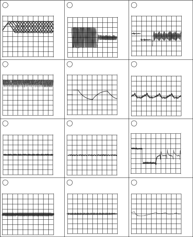
PD-F1007
Waveforms |
1 50T-JUMP: After switching to the pause mode, press |
Note: The encircled numbers denote measuring point in the schematic diagram. |
the manual search key. |
2 FOCUS-IN: Press the play key without loading a disc. |
2 |
TP1-Pin 1: PLAY MODE (RF) |
4' TP1-Pin 2: 50T - JUMP (*1) MODE |
6' IC202-Pin 4: 50T - JUMP (*1) MODE |
||
|
500mV/div 500nsec/div |
|
(TRER) |
|
(TRDR) |
|
|
|
200mV/div 1msec/div |
|
500mV/div 1msec/div |
|
– VC |
|
– VC |
|
– GND |
|
|
|
|
|
|
2 |
TP1-Pin 1: TRACK SEARCH MODE |
5 |
IC202-Pin 3: FOCUS-IN (*2) MODE |
7 |
IC203-Pin 3: PLAY MODE (SPDR) |
|
(RF) |
|
(FODR) |
|
1V/div 50msec/div |
|
500 mV/div 200 μsec/div |
|
1V/div 200msec/div |
|
|
|
– VC |
|
– GND |
|
– GND |
|
|
|
|
|
|
3 |
TP1-Pin 6: PLAY MODE (FOER) |
5 |
IC202-Pin 3: PLAY MODE (FODR) |
7 |
IC203-Pin 3: TRACK SEARCH MODE |
|
100mV/div 10msec/div |
|
1V/div 1msec/div |
|
(SPDR) |
|
|
|
|
|
2V/div 50msec/div |
|
– VC |
|
– GND |
|
– GND |
|
|
|
|
||
4 |
TP1-Pin 2: PLAY MODE (TRER) |
6 |
IC202-Pin 4: PLAY MODE (TRDR) |
8 |
IC202-Pin 9: PLAY MODE (CADR) |
|
200mV/div 1msec/div |
|
500mV/div 1msec/div |
|
0.2V/div 2sec/div |
|
– VC |
|
– GND |
|
– GND |
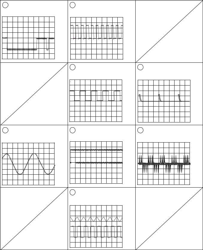
18 |
|
|
|
|
|
|
|
|
|
|
PD-F1007 |
8 |
IC202-Pin 9: TRACK SEARCH MODE |
16 |
IC301-Pin 54 : PLAY MODE (1kHz) |
|
|
|
(CADR) |
|
(BCK) |
|
|
|
2V/div 200msec/div |
|
2V/div 500nsec/div |
|
|
|
– GND |
|
– GND |
|
|
|
|
18 |
IC301-Pin 50 : PLAY MODE (1kHz) |
33 |
IC301-Pin 27 : PLAY MODE (MDP) |
|
|
|
(LRCK) |
|
2V/div 2 μsec/div |
|
|
|
2V/div 10 μsec/div |
|
|
|
|
|
– GND |
|
– GND |
10 |
IC301-Pin 86 : PLAY MODE (1kHz) |
19 |
IC301-Pin 52 : PLAY MODE (1kHz) |
53 IC301-Pin 38 : PLAY MODE |
|
(LOUT 1) |
|||||
|
1V/div 200msec/div |
|
(PCMD) |
|
(PCO) |
|
|
2V/div 500nsec/div |
|
2V/div 10 μsec/div |
|
|
|
|
|
||
|
|
|
– GND |
|
– GND |
|
|
|
|
|
|
|
– GND |
|
|
|
|
|
|
23 |
TRACK SEARCH MODE |
|
|
|
|
|
Upper : TP1-Pin 1 (RF) 1V/div |
|
|
|
|
|
Lower : IC151-Pin 23 (C.OUT) |
|
|
|
|
|
2V/div 50 μsec/div |
|
|
|
|
|
– GND |
|
|
|
|
|
– GND |
|
|
|
|
|
|
|
19 |
|
1 |
|
2 |
|
3 |
|
4 |
|
|
|
|
|
|
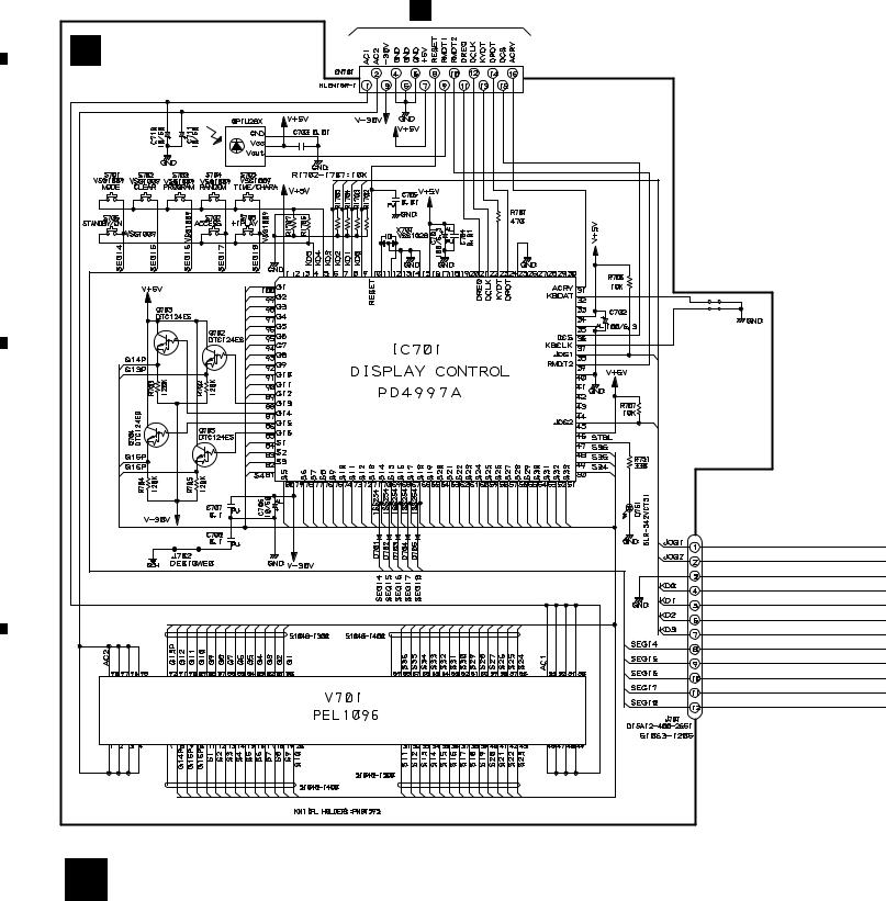
PD-F1007
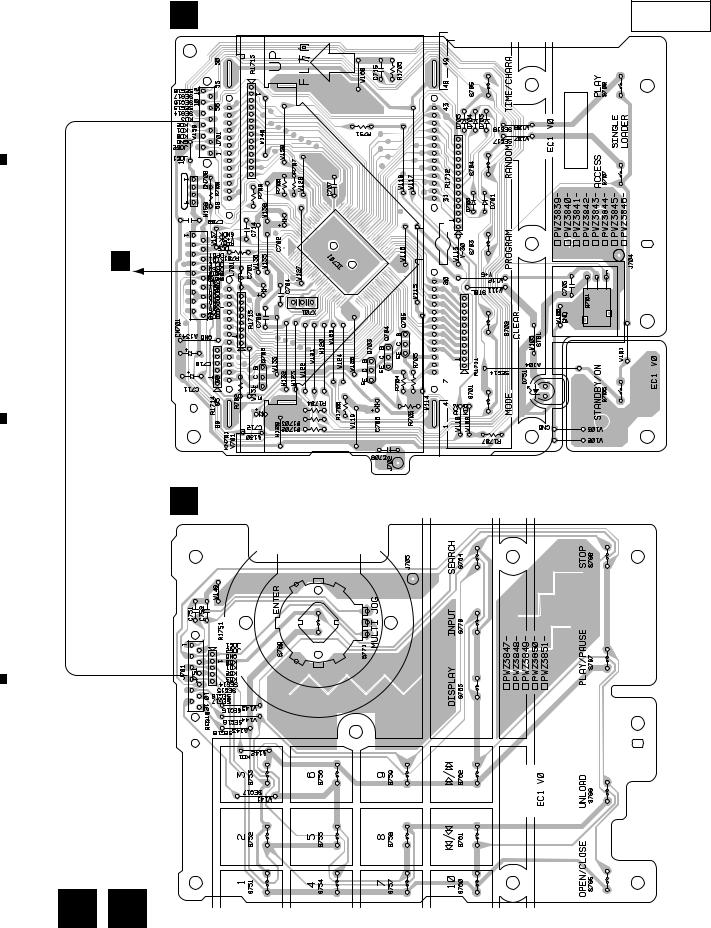
3.4DISPLAY BOARD, FUNCTION BOARD, HEADPHONE BOARD and POWER BOARD ASSEMBLIES
A
|
|
DISPLAY BOARD ASSY |
|
|
|
S701 |
: MODE |
|
|
S702 |
: CLEAR |
|
|
S703 |
: PROGRAM |
|
K CN351 |
S704 |
: RANDOM |
|
S705 : TIME/CHARA |
||
L |
DISPLAY BOARD ASSY |
S706 |
: POWER |
S707 : SINGLE LOADER ACCESS |
|||
(PWZ3839) |
S708 : SINGLE LOADER PLAY |
||
B
C
D
20
|
1 |
|
2 |
|
3 |
|
4 |
|
|
|
|
|
|
||||
|
|
|
|
|
|
5 |
|
6 |
|
7 |
|
8 |
|
|
|
|
|
|
PD-F1007
O POWER BOARD ASSY (PWZ3852)
A
K
CN11
LIVE
NEUTRAL
To AC POWER CORD
B
N HEADPHONE BOARD ASSY (PWZ3860)
K
CN401
C
M FUNCTION(PWZ3847) BOARD ASSY
FUNCTION BOARD ASSY
S751–S760 : DIRECT CUSTOM (1–10)
S761 : Track/Manual search (reverse direction)
S762 : Track/Manual search (forward direction)
S763 : TITLE/DISPLAY
S764 : TITLE/SEARCH
S765 : OPEN/CLOSE
S766 : UNLOAD
S767 : Play/Pause
S768 : Stop
S769 : ENTER
S770 : TITLE/INPUT
S771 : Jog dial
D
21
|
5 |
|
6 |
|
7 |
|
8 |
|
|
|
|
|
|
||||
|
|
|
|
|
|
1 |
|
2 |
|
3 |
|
4 |
|
|
|
|
|
|
PD-F1007
4. PCB CONNECTION DIAGRAM
A4.1 MECHANISM BOARD, DOOR MOTOR BOARD, DOOR SW BOARD and LED BOARD ASSEMBLIES
SIDE A
NOTE FOR PCB DIAGRAMS: |
A MECHANISM BOARD ASSY |
|
1.Part numbers in PCB diagrams match those in the schematic diagrams.
2. A comparison between the main parts of PCB and schematic |
|
|
CARRIAGE |
|||||
diagrams is shown below. |
|
|
|
|
|
|
MOTOR |
|
|
|
|
|
|
|
|
||
Symbol in PCB |
Symbol in Schematic |
Part Name |
SPINDLE |
INSIDE |
M |
|||
Diagrams |
Diagrams |
|
|
|
MOTOR |
|||
|
|
|
|
|
|
|||
|
B C E |
B |
C |
E |
|
M |
|
|
|
|
|
|
|
||||
B C E |
|
|
|
|
Transistor |
|
|
|
|
|
|
|
|
|
|
(PNP1239-C) |
|
|
|
|
|
|
|
|
|
|
|
B |
C |
E |
B |
C |
E |
K CN207 |
B |
|
|
|
|
|
Transistor |
|
|
B C E |
|
|
|
|
with resistor |
|
|
|
|
|
|
|
|
|
|
D |
G |
S |
D |
G |
S |
B DOOR MOTOR BOARD ASSY |
|
|
|
|
|
|
Field effect |
|
|
D G S |
|
|
|
|
transistor |
|
|
|
|
|
|
|
|
|
|
|
|
|
|
|
Resistor array |
|
|
|
|
|
|
|
3-terminal |
(PNP1451-C) |
|
|
|
|
|
|
|
|
|
|
|
|
|
|
regulator |
|
|
3. The parts mounted on this PCB include all necessary parts |
K CN205 |
|||||
|
|
||||||
C |
for several destination. |
|
|
|
|
|
C DOOR SW BOARD ASSY |
For further information for respective destinations, be sure |
|||||||
|
to check with the schematic diagram. |
|
|||||
|
|
|
|||||
|
4. Viewpoint of PCB diagrams |
|
|
|
|
|
|
|
Capacitor |
|
|
|
(PNP1451-C) |
||
Connector
SIDE A
K CN208
P.C.Board |
Chip Part |
SIDE B |
|
|
|
|
D |
LED BOARD ASSY |
|||
|
|
|
|
D
(PNP1451-C)
22
|
1 |
|
2 |
|
3 |
|
4 |
|
|
|
|
|
|
||||
|
|
|
|
|
|
1 |
|
2 |
|
3 |
|
4 |
|
|
|
|
|
|
PD-F1007
4.2 LOADING SW, LOADING BOARD, SENSOR BOARD, RECIEVE BOARD, RADIATE
BOARD, SELECT BOARD and VOLUME BOARD ASSEMBLIES
A
F LOADING BOARD ASSY |
|
SIDE A |
K |
E |
LOADING SW ASSY |
|
|
|
CN203 |
|
|
(PNP1452-B)
(PNP1452-B)
I RADIATE BOARD ASSY
P VOLUME
BOARD ASSY
(PNP1452-B)
G SENSOR BOARD ASSY
H RECIEVE
BOARD ASSY
(PNP1451-C)
(PNP1452-B) |
(PNP1452-B) |
B
C
J SELECT BOARD ASSY
K
CN204
D
(PNP1452-B)
23
|
1 |
|
2 |
|
3 |
|
4 |
|
|
|
|
|
|
||||
|
|
|
|
|
|
1 |
|
2 |
|
3 |
|
4 |
|
|
|
|
|
|
PD-F1007
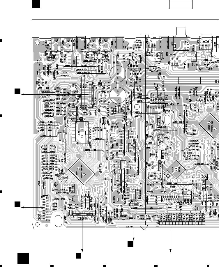
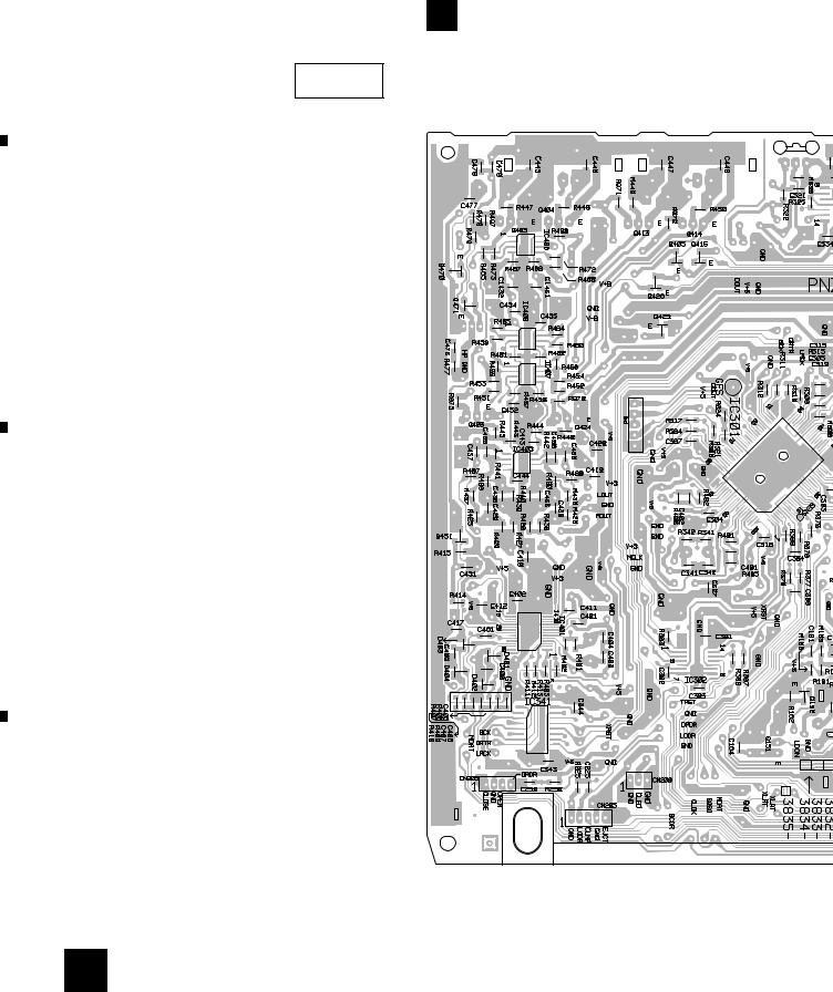
4.3 MAIN BOARD ASSY
A |
K MAIN BOARD ASSY |
SIDE A |
|
|
|
IC23 |
|
|
|
|
|
|
|
IC35 IC31 |
IC202 |
IC21 |
|
|
|
IC25 |
Q351 |
IC36 IC32 |
IC201 |
IC203 |
IC34 |
Q391 |
Q151 |
|
|
|
|
|
|
VR152 |
VR153 |
|
|
|
|
|
|
VR156 |
|
|
|
|
|
|
|
VR151 |
|
|
|
|
|
|
|
VR155 |
|
|
|
|
|
|
|
VR154 |
|
B |
|
|
|
|
|
|
|
O |
|
|
|
|
|
|
|
J11 |
|
|
|
|
|
|
|
C |
|
|
|
|
|
|
|
L |
|
|
|
|
|
|
|
CN701 |
|
|
|
|
|
|
|
D |
|
|
|
|
|
|
|
|
|
|
A CN610 |
|
|
||
24 |
J J601 |
|
|
|
|
To PICKUP ASSY |
|
|
|
|
|
|
|
|
|
1 |
2 |
|
|
3 |
|
|
4 |
|
5 |
|
6 |
|
7 |
|
8 |
|
|
|
|
PD-F1007
SIDE A
|
|
|
Q404 |
|
|
Q151 |
Q414 |
Q413 |
Q424 |
Q403 |
Q423 |
VR153
N HEADPHONE BOARD ASSY
(PNP1451-C)
|
(PNP1450-A) |
D J1601 |
B J631 |
F J651 |
|
25
A
B
C
D
|
5 |
|
6 |
|
7 |
|
8 |
|
|
|
|
|
|
||||
|
|
|
|
|
|
1 |
|
2 |
|
3 |
|
4 |
|
|
|
|
|
|
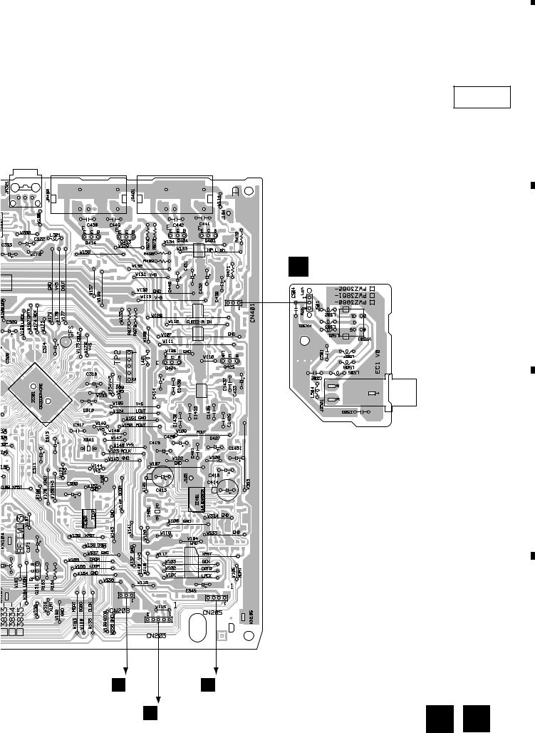
PD-F1007
A
K MAIN BOARD ASSY
SIDE B
|
IC406 |
|
|
|
|
|
IC408 |
|
|
|
|
Q470 |
IC407 |
|
|
|
|
IC405 |
|
|
|
|
|
Q471 |
IC401 |
Q426 |
|
|
|
Q451 |
IC341 |
Q425 Q405 Q415 |
IC301 |
Q152 |
I |
B
C
D |
(PNP1450-A) |
26
|
1 |
|
2 |
|
3 |
|
4 |
|
|
|
|
|
|
||||
|
|
|
|
|

|
|
|
5 |
|
|
6 |
7 |
8 |
|
|
|
|
|
|
|
|
PD-F1007 |
|
|
|
|
|
|
|
|
A |
|
|
|
|
|
|
|
|
SIDE B |
|
|
|
|
|
|
Q382 |
|
|
|
|
|
|
|
|
Q363 |
|
|
|
|
|
|
|
|
Q381 |
IC352 |
|
IC301 |
Q152 |
IC331 |
IC151 |
Q406 |
Q416 |
Q362 |
IC351 |
|
|
|
|
|
|
|
|
|
B |
|
|
|
|
|
|
|
|
C |
|
|
|
|
|
|
|
|
D |
|
|
|
|
|
|
|
|
27 |
|
|
|
5 |
|
|
6 |
7 |
8 |
|
1 |
|
2 |
|
3 |
|
4 |
|
|
|
|
|
|
PD-F1007
4.4 DISPLAY BOARD and FUNCTION BOARD ASSEMBLIES |
|
L DISPLAY BOARD ASSY |
SIDE A |
A |
|
K |
|
CN351 |
|
B |
|
(PNP1451-C) |
|
M FUNCTION BOARD ASSY |
|
C |
|
D
(PNP1451-C)
28
|
1 |
|
2 |
|
3 |
|
4 |
|
|
|
|
|
|
||||
|
|
|
|
|
|
1 |
|
2 |
|
3 |
|
4 |
|
|
|
|
|
|
PD-F1007
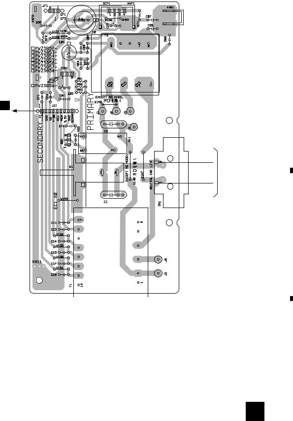
4.5 POWER BOARD ASSY
A
O |
POWER BOARD ASSY |
SIDE A |
|
|
|
|
|
|
|
|
|
|
|
|
|
|
|
|
|
K |
B |
CN11
LIVE |
CORD |
|
POWERACTo |
||
NEUTRAL |
||
|
||
|
C |
|
(PNP1451-C) |
|
D
29
|
1 |
|
2 |
|
3 |
|
4 |
|
|
|
|
|
|
||||
|
|
|
|
|
PD-F1007
5. PCB PARTS LIST
NOTES:  Parts marked by "NSP" are generally unavailable because they are not in our Master Spare Parts List.
 The
The  mark found on some component parts indicates the importance of the safety factor of the part. Therefore, when replacing, be sure to use parts of identical designation.
 When ordering resistors, first convert resistance values into code form as shown in the following examples.
Ex.1 When there are 2 effective digits (any digit apart from 0), such as 560 ohm and 47k ohm (tolerance is shown by J=5%,
and K=10%). |
|
|
|
|
|
|
|
560 |
|
56 x 101 |
|
561 |
RD1/4PU 5 |
6 |
1 J |
|
|
||||||
47k |
|
47 x 103 |
|
473 |
RD1/4PU 4 |
7 |
3 J |
|
|
||||||
0.5 |
|
R50 |
|
|
RN2H R 5 0 K |
||
|
|
|
|||||
1 |
|
1R0 |
|
|
RS1P 1 R 0 K |
|
|
|
|
|
|
||||
Ex.2 When there are 3 effective digits (such as in high precision metal film resistors). |
|
|
|||||
5.62k |
|
562 x 101 |
|
5621 |
RN1/4PC 5 6 2 1 F |
||
|
|
||||||
Mark No. Description Part No.
LIST OF PCB ASSEMBLIES
NSP MOTHER BOARD ASSY |
PWM2252 |
||||
|
|
|
|
MAIN BOARD ASSY |
PWZ3822 |
|
|
|
|
||
NSP |
MECHANISM BOARD ASSY |
PWX1572 |
|||
NSP |
|
|
|
SENSOR BOARD ASSY |
PWZ3781 |
|
|
|
|||
NSP |
|
|
|
SELECT BOARD ASSY |
PWZ3785 |
|
|
|
|||
NSP |
|
|
|
LOADING BOARD ASSY |
PWZ3788 |
|
|
|
|||
NSP |
|
|
|
LOADING SW BOARD ASSY |
PWZ3790 |
|
|
|
|||
NSP |
|
|
|
RADIATE BOARD ASSY |
PWZ3791 |
|
|
|
|||
NSP |
|
|
|
RECIEVE BOARD ASSY |
PWZ3792 |
|
|
|
|||
NSP SUB BOARD ASSY |
PWX1576 |
||||
|
|
|
|
DISPLAY BOARD ASSY |
PWZ3839 |
|
|
|
|
||
NSP |
|
|
|
FUNCTION BOARD ASSY |
PWZ3847 |
|
|
|
|||
|
|
|
|
POWER BOARD ASSY |
PWZ3852 |
|
|
|
|
||
NSP |
|
|
|
HEADPHONE BOARD ASSY |
PWZ3860 |
|
|
|
|||
NSP |
|
|
|
DOOR MOTOR BOARD ASSY |
PWZ3863 |
|
|
|
|||
NSP |
|
|
|
DOOR SW BOARD ASSY |
PWZ3865 |
|
|
|
|||
|
|
|
|
VOLUME BOARD ASSY |
PWZ3866 |
|
|
|
|
||
NSP |
|
|
|
LED BOARD ASSY |
PWZ3867 |
|
|
|
|||
NSP |
SERVO MECHANISM ASSY GM |
PXA1591 |
|||
|
|
|
|
MECHANISM BOARD ASSY |
PWX1192 |
|
|
|
|
||
 MECHANISM BOARD ASSY
SWITCHES AND RELAYS
S610 DSG1016
OTHERS
CN610 MT CONNECTOR 173979-4
 SENSOR BOARD ASSY
SEMICONDUCTORS
Q604 |
2SC1740S |
Q601, Q602 |
DTC124ES |
D601, D602 |
GP1S58V |
RESISTORS
All Resistors |
RD1/4PU |
J |
Mark No. Description Part No.
OTHERS
|
CABLE HOLDER |
51048-0300 |
|
CABLE HOLDER |
51048-0700 |
J603 |
3P JUMPER WIRE |
D20PDD0310E |
J602 |
7P JUMPER WIRE |
D20PDD0725E |
J605 |
3P JUMPER WIRE |
D20PDY0310E |
 SELECT BOARD ASSY
OTHERS
|
CABLE HOLDER |
51048-0700 |
|
CABLE HOLDER |
51048-0900 |
J601 |
9P JUMPER WIRE |
D20PDY0930G |
 LOARDING BOARD ASSY
OTHERS
|
CABLE HOLDER |
51048-0300 |
|
CABLE HOLDER |
51048-0500 |
J652 |
3P JUMPER WIRE |
D20PDD0310E |
J651 |
5P JUMPER WIRE |
D20PDY0530E |
 LOARDING SW BOARD ASSY
OTHERS
CABLE HOLDER |
51048-0300 |
REAF SWITCH |
VSK1011 |
RADIATE BOARD ASSY |
|
SEMICONDUCTORS |
|
D611 |
GL381J |
OTHERS |
|
CABLE HOLDER |
51048-0300 |
L.E.D. HOLDER |
RNK1795 |
30
 Loading...