


KEYBORD |
INPUT |
ORDER NO.
RRV2105
FILE-TYPE COMPACT DISC PLAYER
PD-F1007
THIS MANUAL IS APPLICABLE TO THE FOLLOWING MODEL(S) AND TYPE(S).
Type |
|
Model |
Power Requirement |
Remarks |
|
|
|||
|
PD-F1007 |
|||
|
|
|
|
|
|
|
|
|
|
MY |
|
AC220-230V |
|
|
|
|
|
|
|
CONTENTS |
|
1. SAFETY INFORMATION .................................... |
2 |
2. EXPLODED VIEWS AND PARTS LIST ............. |
3 |
3. SCHEMATIC DIAGRAM ................................... |
10 |
4. PCB CONNECTION DIAGRAM ....................... |
22 |
5. PCB PARTS LIST ............................................. |
30 |
6. ADJUSTMENT .................................................. |
34 |
7. GENERAL INFORMATION .............................. |
44 |
7.1 PARTS ....................................................... |
44 |
7.1.1 IC ....................................................... |
44 |
7.1.2 DISPLAY ........................................... |
47 |
7.2 DIAGNOSIS ................................................ |
48 |
7.2.1 DISASSEMBLY ................................. |
48 |
7.2.2 ERROR CCHECK DISPLAY ............. |
51 |
7.2.3 EXPLANATION OF DISC |
|
DETECTION ...................................... |
52 |
7.3 BLOCK DIAGRAM ...................................... |
54 |
8. PANEL FACILITIES AND SPECIFICATIONS |
|
....................................................... |
55 |
PIONEER ELECTRONIC CORPORATION 4-1, Meguro 1-Chome, Meguro-ku, Tokyo 153-8654, Japan PIONEER ELECTRONICS SERVICE, INC. P.O. Box 1760, Long Beach, CA 90801-1760, U.S.A.
PIONEER ELECTRONIC (EUROPE) N.V. Haven 1087, Keetberglaan 1, 9120 Melsele, Belgium PIONEER ELECTRONICS ASIACENTRE PTE. LTD. 253 Alexandra Road, #04-01, Singapore 159936
 PIONEER ELECTRONIC CORPORATION 1999
T–ZZR FEB. 1999 Printed in Japan
PD-F1007
1. SAFETY INFORMATION
This service manual is intended for qualified service technicians; it is not meant for the casual do-it-yourselfer. Qualified technicians have the necessary test equipment and tools, and have been trained to properly and safely repair complex products such as those covered by this manual.
Improperly performed repairs can adversely affect the safety and reliability of the product and may void the warranty. If you are not qualified to perform the repair of this product properly and safely, you should not risk trying to do so and refer the repair to a qualified service technician.
|
|
|
|
|
|
|
|
|
|
IMPORTANT |
|
|
|
|
|
|
|
THIS PIONEER APPARATUS CONTAINS |
|
|
LASER DIODE CHARACTERISTICS |
|
||||
|
MAXIMUM OUTPUT POWER: 7 mw |
|||||||
LASER OF CLASS 1. |
|
|||||||
|
WAVELENGTH: 780 – 785 nm |
|||||||
SERVICING OPERATION OF THE APPARATUS |
|
|||||||
|
|
|
|
|||||
S H O U L D B E D O N E B Y A S P E C I A L L Y |
|
|
|
|
||||
INSTRUCTED PERSON. |
|
|
|
|
||||
|
|
|
|
|
|
|
|
|
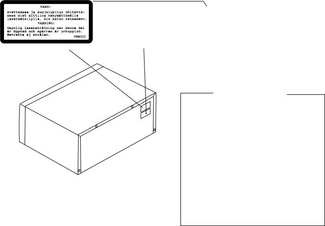
LABEL CHECK
PD-F1007/MY
REAR
Additional Laser Caution
1.Laser Interlock Mechanism
The position of the switch (VSK1011) for detecting loading state is detected by the system microprocessor, and the design prevents laser diode oscillation when the switch (VSK1011) is not on CLMP terminal side (CLMP signal is OFF or high level).
Thus, the interlock will no longer function if the switch (VSK1011) is deliberatery set to CLMP terminal side. (low level)
The interlock also does not function in the test mode *. Laser diode oscillation will continue, if pin 33 of CXA1782CQ (IC151) on the MOTHER BOARD ASSY is connected to GND, or pin 89 of IC351 (LDON) is connected to low level (ON), or else the terminals of Q151 are shorted to each other (fault condition).
2.When the cover is opened, close viewing of the objective lens with the naked eye will cause exposure to a Class 1 laser beam.
Refer to page 35 .
2
PD-F1007
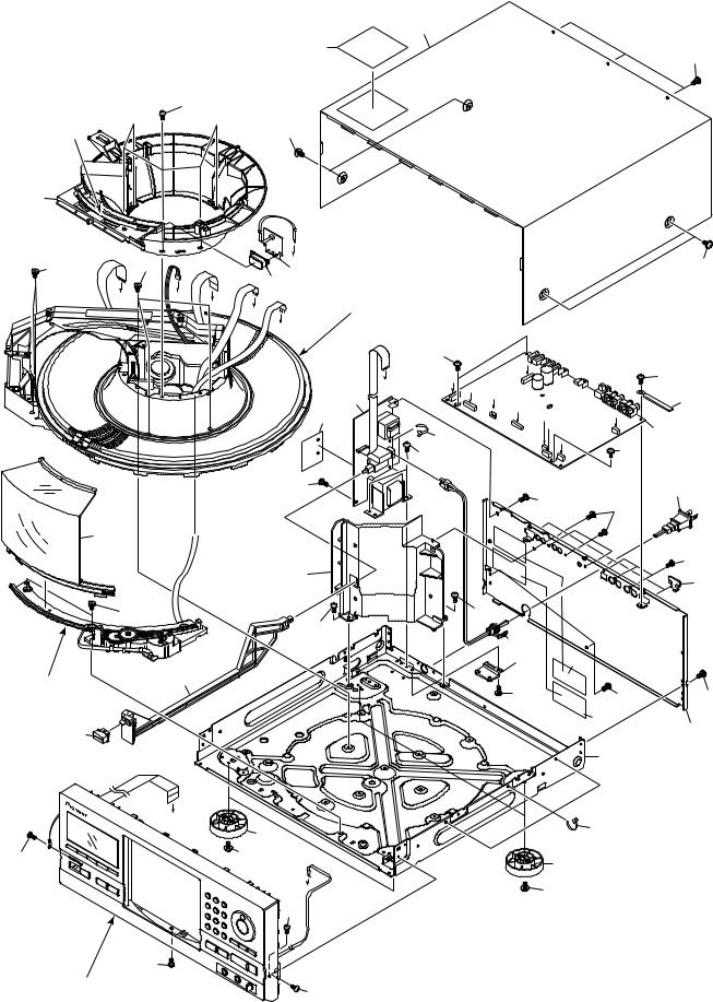
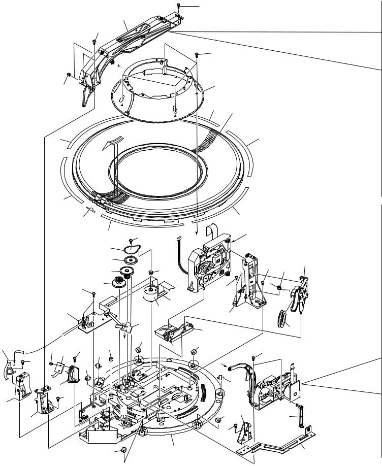
2. EXPLODED VIEWS AND PARTS LIST
NOTES : |
Parts marked by “ NSP ” are generally unavailable because they are not in our Master Spare Parts List. |
|
|
The |
mark found on some component parts indicates the importance of the safety factor of the part. |
|
Therefore, when replacing, be sure to use parts of identical designation. |
|
|
Screw adjacent to mark on the product are used for disassembly. |
|
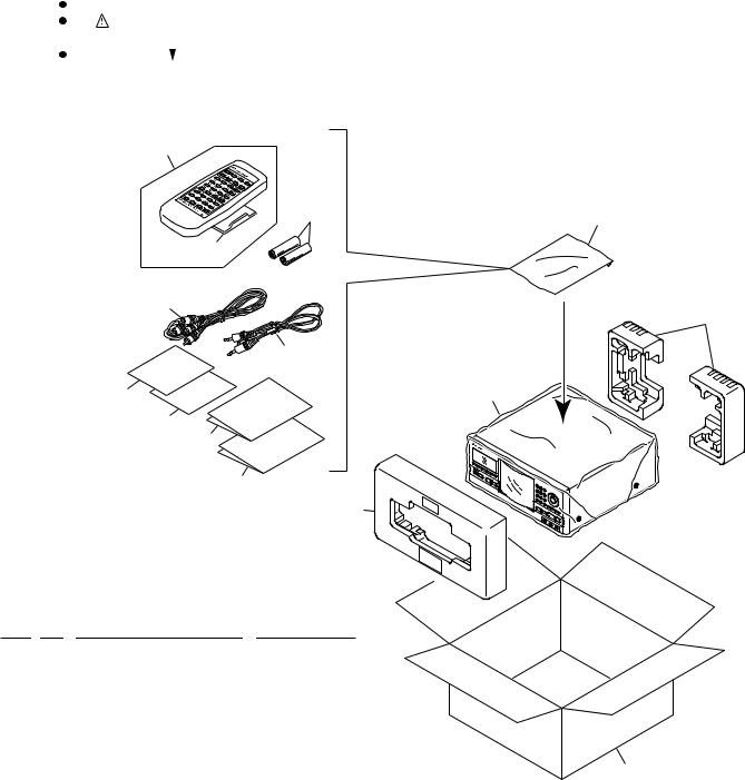
2.1 PACKING
8
10 |
5 |
9
12
2
11
13 |
4 |
14
6
7
1
PACKING PARTS LIST |
|
||
Mark |
No. |
Description |
Part No. |
|
1 |
Styrol Protector F |
PHA1325 |
|
2 |
Styrol Protector R |
PHA1326 |
|
3 |
Packing Case |
PHG2368 |
|
4 |
Packing Sheet |
RHC1023 |
|
5 |
Polyethylene Bag |
Z21–038 |
|
|
(0.03 × 230 × 340) |
|
|
6 |
Operating Instructions |
PRD1052 |
|
|
(English/French/German/Italian) |
3 |
|
7 |
Operating Instructions |
PRE1279 |
|
|
(Dutch/Swedish/Spanish/Portuguese) |
|
|
8 |
Remote Control Unit |
PWW1139 |
|
|
(CD-PD094) |
|
|
9 |
Battery Cover |
AZA7204 |
NSP |
10 |
Dry Cell Batteries (R6P, AA) |
VEM–013 |
|
11 |
Control Cable (L=1 m) |
PDE1247 |
|
12 |
Audio Cable (L=1 m) |
PDE1248 |
NSP |
13 |
Warranty Card |
ARY7022 |
|
14 |
KEY Board Label |
PRW1527 |
3
PD-F1007
2.2 EXTERIOR (1/2)
|
|
|
8 |
|
|
|
|
|
19 |
|
|
|
|
22 |
|
|
|
2 |
|
|
21 |
|
|
14 |
|
|
|
|
|
(1/2) |
|
|
|
|
|
6 |
|
6 |
F |
|
|
|
3 |
|
|
||
|
|
|
|
|
|
|
|
D |
15 |
|
|
|
C |
|
|
|
|
|
E |
Refer to " 2.3 EXTERIOR (2/2)". |
|
|
|
|
|
|
|
||
|
|
|
G |
|
|
|
|
|
H |
|
|
|
|
|
22 |
I |
|
|
|
|
A |
|
|
|
|
|
|
|
|
|
|
|
I |
C D |
|
|
|
|
2 |
E |
|
|
|
|
25 |
|
|
|
|
|
F G |
|
|
|
|
|
23 |
|
|
|
|
|
|
H |
|
|
|
|
20 |
|
|
|
|
|
20 |
|
|
|
|
|
|
20 |
|
|
17 |
|
|
|
|
|
|
|
11 (1/2) |
|
|
|
6 |
|
|
20 |
|
|
|
|
20 |
|
|
|
|
|
|
4 |
|
|
|
|
|
11 (2/2) |
24 |
|
|
|
|
|
|
Hood Base Assy |
|
12 |
|
|
|
|
|
|
20 |
|
|
|
|
|
|
|
|
16 |
|
|
|
|
|
A |
10 |
|
|
|
|
20 |
20 |
10 |
|
||
|
B |
20 |
|
|
|
|
20 |
|
20 |
|
|
Refer to " 2.5 FRONT PANEL |
|
20 |
ASSY SECTION". |
|
|
B
22
20
20
18
7
23
20
21
22
13
1
5
20
14
(2/2)
20
9
4
PD-F1007
No. 14: Center Pole |
|
Hood Base Assy Section |
|
|
|
|
|
Cut |
14 (2/2) |
35 |
|
|
|
|
|
|
Cut |
28 |
|
|
|
30 |
|
|
|
32 |
33 |
14 (1/2) |
|
2 |
|
|
|
||
|
|
|
2 |
|
|
31 |
|
No. 11: Trans Cover |
|
35 |
|
|
|
|
|
11(1/2) |
|
1 |
29 |
|
11(2/2) |
|
|
Cut |
|
27 |
26 |
|
|
||
|
|
|
|
|
|
|
34 |
EXTERIOR (1/2) PARTS LIST
Mark |
No. |
|
Description |
|
Part No. |
|
Mark |
No. |
|
Description |
|
Part No. |
|||
|
|
|
|
|
|
|
|
|
|
|
|
|
|
|
|
|
|
1 |
|
MAIN BOARD ASSY |
|
PWZ3823 |
|
|
|
|
|
|
|
|
|
|
|
|
|
|
|
Hood Base Assy Section |
|
|
|||||||
|
|
|
|
|
|
|
|
||||||||
|
|
|
|
|
|
|
|
||||||||
|
|
2 |
|
POWER BOARD ASSY |
|
PWZ3853 |
|
|
|
|
|||||
|
|
|
|
|
|
|
|
|
|
|
|
|
|||
NSP |
3 |
|
LED BOARD ASSY |
|
PWZ3867 |
|
NSP |
26 |
|
DOOR MOTOR BOARD ASSY |
|
PWZ3863 |
|||
|
|
4 |
|
Strain Relief |
|
CM–22B |
|
NSP |
27 |
|
DOOR SW BOARD ASSY |
|
PWZ3865 |
||
|
|
5 |
|
AC Power Cord |
|
VDG1061 |
|
|
|
|
28 |
|
Belt |
|
PEB1300 |
|
|
|
|
|
|
|
|
|
|
|
29 |
|
Motor Pulley |
|
PNW1634 |
|
|
6 |
|
Screw C |
|
PBA1106 |
|
|
|
|
30 |
|
Gear AW |
|
PNW2906 |
NSP |
7 |
|
Under Base |
|
PNA2421 |
|
|
|
|
|
|
|
|
|
|
|
|
8 |
|
Bonnet Case |
|
PYY1255 |
|
|
|
|
31 |
|
Hood Base |
|
PNW2791 |
|
|
9 |
|
Rear Base |
|
PNA2491 |
|
|
|
|
32 |
|
Gear M1 |
|
PNW2800 |
|
|
10 |
|
Insulator |
|
PNW2766 |
|
|
|
|
33 |
|
Gear Pulley |
|
VNL1662 |
|
|
|
|
|
|
|
|
|
|
|
34 |
|
Slider Motor |
|
VXM1033 |
|
|
11 |
|
Trans Cover |
|
PNW2802 |
|
|
|
|
35 |
|
Screw |
|
IPZ20P080FMC |
|
|
12 |
|
Joint |
|
PNW2805 |
|
|
|
|
|
|
|
|
|
|
|
13 |
|
Cord Clamper |
|
RNH–184 |
|
|
|
|
1 |
|
|
|
|
|
|
14 |
|
Center Pole |
|
PNW2792 |
|
|
|
|
|
Froil 397 (for service) |
|
GYA1001 |
|
|
|
15 |
|
CR Lens |
|
PNW2816 |
|
|
|
|
2 |
|
Ha Narl PN955R (for service) |
|
GEM1016 |
|
|
16 |
|
POWER Button |
|
PAC1884 |
|
|
|
|
|
|
|
|
|
|
|
17 |
|
Hood |
|
PNW2793 |
|
|
|
|
|
|
|
|
|
|
|
18 |
|
Caution Label (HE) |
|
PPW1233 |
|
|
|
|
|
|
|
|
|
|
|
19 |
|
Caution Label |
|
PRW1517 |
|
|
|
|
|
|
|
|
|
|
|
20 |
|
Screw |
|
BBZ30P080FZK |
|
|
|
|
|
|
|
|
|
|
|
21 |
|
Screw |
|
FBT40P080FZK |
|
|
|
|
|
|
|
|
|
|
|
22 |
|
Screw |
|
IPZ30P080FMC |
|
|
|
|
|
|
|
|
|
|
|
23 |
|
Binder |
|
ZCA–SKB90BK |
|
|
|
|
|
|
|
|
|
|
|
24 |
|
Caution Label |
|
VRW1094 |
|
|
|
|
|
|
|
|
|
|
|
25 |
|
Screw Cover |
|
PNM1340 |
|
|
|
|
|
|
|
|
|
|
|
2 |
|
Ha Narl PN955R (for service) |
|
GEM1016 |
|
|
|
|
|
|
|
|
|
5
PD-F1007
2.3 EXTERIOR (2/2)
11
44
44
45
52
1
7 |
52 |
52 |
|
|
6 |
50
32
41
50
38
39
52
53
52
52

 B
B
40
44 33
44
46
|
|
|
|
44 |
|
44 |
51 |
A |
|
Refer to " 2.4 FLOAT BASE |
|
|
ASSY SECTION". |
||||
|
|
||||
9 |
|
|
|
|
|
10 |
|
|
|
|
21 |
|
|
|
|
52 |
|
35 |
|
31 |
|
8 |
|
|
|
|
|||
|
|
|
|
|
|
36 |
|
|
52 |
|
|
|
|
|
|
|
|
|
|
2 |
|
|
|
|
|
43 |
20 |
|
|
|
|
|
|
|
|
|
5 |
|
|
|
|
|
|
19 |
|
|
15 |
|
32 |
|
|
|
|
42 |
C |
32 |
|
|
|
1 |
2 |
|
52 |
|
|
32 |
|
|
|||
1 |
B |
|
|
||
|
|
|
|
||
1 |
|
A |
|
|
|
|
|
|
32 |
|
|
|
1 |
|
|
|
|
|
|
|
|
|
|
|
|
|
1 |
|
|
|
C |
|
32 |
37 |
28 |
|
|
|
|
||
1 |
|
|
|
|
|
|
1 |
|
|
|
|
|
|
47 |
|
|
|
|
1 |
|
|
|
|
32 |
|
34 |
|
|
30 |
6
52
27
23
25
12
24
26
 2 [ Apply the Guide R (No. 27) also at the same position.]
14
22
Note) Tightening Torque: 2 kg·cm |
b |
|
|
51 |
|
|
17 |
29 |
|
9 |
|
|
10 |
b |
49 |
|
|
|
16 |
13 |
4 |
a |
|
|
|
|
|
48 |
|
|
a |
|
|
1 |
18 |
|
|
31 |
43
3
PD-F1007
EXTERIOR (2/2) PARTS LIST
Mark |
No. |
|
Description |
|
Part No. |
|
|
|
|
|
|
|
|
|
|
|
|
|
|
|
NSP |
1 |
|
SENSOR BOARD ASSY |
|
PWZ3781 |
|
NSP |
2 |
|
SELECT BOARD ASSY |
|
PWZ3785 |
|
NSP |
3 |
|
LOADING BOARD ASSY |
|
PWZ3788 |
|
NSP |
4 |
|
LOADING SW BOARD ASSY |
|
PWZ3790 |
|
NSP |
5 |
|
RADIATE BOARD ASSY |
|
PWZ3791 |
|
NSP |
6 |
|
RECEIVE BOARD ASSY |
|
PWZ3792 |
|
NSP |
7 |
|
VOLUME BOARD ASSY |
|
PWZ3866 |
|
|
|
8 |
|
Clamp Spring |
|
ABH7107 |
|
|
9 |
|
Loading Belt |
|
AEB7029 |
|
|
10 |
|
Gear Pulley B |
|
ANW7062 |
|
|
11 |
|
Roller B |
|
ANW7075 |
NSP |
12 |
|
Arm Spring |
|
PBH1225 |
|
|
|
13 |
|
L Arm Spring |
|
PBH1226 |
|
|
14 |
|
Sheet |
|
PED1028 |
|
|
15 |
|
Clamper |
|
PNW2743 |
|
|
16 |
|
Gear 1 |
|
PNW2819 |
|
|
17 |
|
Gear 2 |
|
PNW2820 |
|
|
18 |
|
Gear Holder |
|
PNW2822 |
|
|
19 |
|
Slider Cam |
|
PNW2823 |
|
|
20 |
|
Clamp Support |
|
PNW2826 |
|
|
21 |
|
Clamp Holder |
|
PNW2827 |
|
|
22 |
|
Drive Arm |
|
PNW2829 |
NSP |
23 |
|
Link |
|
PNW2830 |
|
NSP |
24 |
|
L Slider |
|
PNW2831 |
|
NSP |
25 |
|
L Arm |
|
PNW2832 |
|
|
|
26 |
|
Guide L |
|
PNW2833 |
|
|
27 |
|
Guide R |
|
PNW2834 |
|
|
28 |
|
Link L |
|
PNW2844 |
|
|
29 |
|
Drive Cam |
|
PNW2873 |
|
|
30 |
|
Lock Plate |
|
PNA2438 |
|
|
31 |
|
Motor Pulley |
|
PNW1634 |
|
|
32 |
|
Roller |
|
PNW2647 |
|
|
33 |
|
Disc Rack |
|
PNW2790 |
|
|
34 |
|
Rack Base |
|
PNW2835 |
|
|
35 |
|
ST Gear 0.6 |
|
PNW2836 |
|
|
36 |
|
ST Gear 1.0 |
|
PNW2837 |
|
|
37 |
|
Disc Divider |
|
PNW2838 |
|
|
38 |
|
Guide Support L |
|
PNW2839 |
|
|
39 |
|
Guide Support R |
|
PNW2840 |
|
|
40 |
|
Disc Guard |
|
PNW2841 |
|
|
41 |
|
Sensor Stay |
|
PNW2842 |
|
|
42 |
|
Guide Roller |
|
PNW2843 |
|
|
43 |
|
Slider Motor |
|
VXM1033 |
|
|
44 |
|
Rack Label |
|
PAM1770 |
|
|
45 |
|
S Label |
|
PAM1771 |
|
|
46 |
|
+1 Label |
|
PRW1507 |
|
|
47 |
|
Screw |
|
BBZ30P080FZK |
|
|
48 |
|
Screw |
|
BMZ26P040FZK |
|
|
49 |
|
Screw |
|
BPZ26P060FMC |
|
|
50 |
|
Screw |
|
BPZ30P100FCU |
|
|
51 |
|
Screw |
|
IPZ20P080FMC |
|
|
52 |
|
Screw |
|
PPZ30P080FMC |
|
|
53 |
|
Arm Assy |
|
PXA1615 |
|
|
1 |
|
Froil 397 (for service) |
|
GYA1001 |
|
|
2 |
|
Ha Narl PN955R (for service) |
|
GEM1016 |
7
PD-F1007
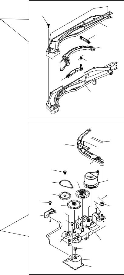
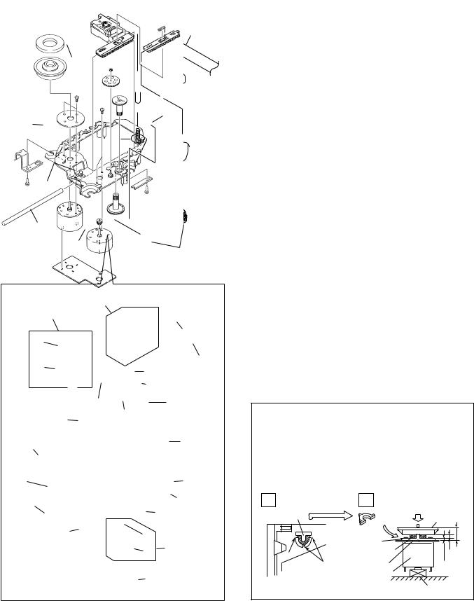
2.4 FLOAT BASE ASSY SECTION
30
26
28
33
27
29
32
31
29
5
|
10 |
|
|
24 |
|
|
|
|
|
17 |
|
|
|
|
19 |
|
|
|
25 |
|
|
16 |
|
|
|
|
15 |
|
|
|
|
3 |
|
|
|
|
|
|
|
|
|
|
14 |
2 |
|
|
|
|
|
|
18 |
|
|
|
20 |
|
|
|
4 |
|
|
|
|
|
23 |
|
|
|
21 |
12 |
|
|
|
22 |
|
|
|
|
|
|
|
|
|
1 |
|
6 |
|
8 |
|
|
|
|
|
|
|
|
|
9 |
7 |
|
|
|
11 |
|
FLOAT BASE ASSY SECTION PARTS LIST
Mark |
No. |
|
Description |
|
Part No. |
|
|
|
|
|
|
|
|
|
|
1 |
|
Gear 1 |
|
PNW2052 |
|
|
|
|
|||
|
|
2 |
|
Gear 2 |
|
PNW2053 |
|
|
3 |
|
Gear 3 |
|
PNW2054 |
|
|
4 |
|
Carriage Base |
|
PNW2699 |
|
|
5 |
|
Pickup Assy - S |
|
PEA1335 |
|
|
6 |
|
D.C. Motor Assy (SPINDLE) |
|
PEA1235 |
|
|
7 |
|
Carriage DC Motor Assy |
|
PEA1246 |
|
|
8 |
|
Pinion Gear |
|
PNW2055 |
|
|
9 |
|
Carriage DC Motor/0.3W |
|
PXM1027 |
|
|
10 |
|
Disc Table Assy |
|
PEA1314 |
|
|
11 |
|
Mechanism Board Assy |
|
PWX1192 |
|
|
12 |
|
Guide Bar |
|
PLA1094 |
|
|
13 |
|
………… |
|
|
|
|
14 |
|
Screw |
|
JFZ17P025FZK |
|
|
15 |
|
Screw |
|
JFZ20P040FMC |
|
|
16 |
|
Washer |
|
WT12D032D025 |
|
|
17 |
|
Clamp Magnet |
|
PMF1014 |
|
|
18 |
|
Yoke M |
|
PNB1312 |
NSP |
19 |
|
Disc Table |
|
PNW2410 |
|
NSP |
20 |
|
Float Angle |
|
ANB7020 |
|
|
|
21 |
|
Gear Stopper |
|
PNB1303 |
|
|
22 |
|
Screw |
|
BPZ20P060FMC |
|
|
23 |
|
Screw |
|
BPZ26P100FMC |
|
|
24 |
|
PU Rack Spring |
|
ABH7077 |
|
|
25 |
|
Rack Holder |
|
PNW2056 |
|
|
26 |
|
Float Base |
|
PNW2828 |
|
|
27 |
|
Screw |
|
ABA7009 |
|
|
28 |
|
Float Spring |
|
ABH7049 |
|
|
29 |
|
Float Rubber |
|
AEB7028 |
|
|
30 |
|
16P F·F·C/30V |
|
PDD1185 |
NSP |
31 |
|
Servo Mechanism Assy GM |
|
PXA1591 |
|
|
|
32 |
|
Connector Assy (4P) |
|
RDE1043 |
|
|
33 |
|
Sheet |
|
PED1028 |
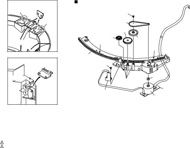
¦ How to Install the Disc Table
1 Use nipper or other tool to cut the three sections marked A in figure 1. Then remove the spacer
2While supporting the spindle motor shaft with the stopper, put spacer on top of the yoke M, and stick the disc table on top (takes about 9kg pressure). Detach the spacer.
1 |
|
2 |
(Pressure of about 9 kg) |
|
|
|
|
|
Spacer |
Spacer |
Disc Table |
|
|
||
|
|
|
6.9mm
|
Yoke M |
|
|
A |
Spacer Setting |
0.9mm |
|
Position |
|||
±0.05mm |
|||
A |
Carriage Base |
1.2mm |
Spindle Motor
Float Base
Stopper
8

PD-F1007
2.5 FRONT PANEL ASSY SECTION
4
14
1
19
19
5
16 |
|
19 |
|
19 |
|
|
|
|
15 |
|
|
9 |
|
|
17 |
13 |
19 |
|
22 |
21 |
|
|
2 |
20
6
10
3
18
12
7
11
8
FRONT PANEL ASSY SECTION PARTS LIST
Mark |
No. |
|
Description |
|
Part No. |
|
Mark No. |
|
Description |
|
Part No. |
|||
|
|
|
|
|
|
|
|
|
|
|
|
|
|
|
|
|
|
|
|
|
|
|
|
|
|
|
|
|
|
|
|
|
|
|
|
|
|
|
|
|
|
|
|
|
|
|
1 |
|
DISPLAY BOARD ASSY |
|
PWZ3840 |
13 |
|
FC Cover |
|
PNM1323 |
|||
NSP |
2 |
|
FUNCTION BOARD ASY |
|
PWZ3847 |
14 |
|
PCB Cover |
|
PNM1324 |
||||
NSP |
3 |
|
HEADPHONE BOARD ASSY |
|
PWZ3860 |
15 |
|
LED Lens |
|
PNW2019 |
||||
|
|
4 |
|
18P F·F·C/30V |
|
PDD1188 |
|
|
|
|
|
|
|
|
|
|
5 |
|
MODE Button |
|
PAC1880 |
16 |
|
Operation Panel |
|
PNW2909 |
|||
|
|
|
|
|
|
|
17 |
|
Sensor Lens |
|
PNW2804 |
|||
|
|
6 |
|
PLAY Button |
|
PAC1881 |
18 |
|
Rotary Knob |
|
RAC1903 |
|||
|
|
7 |
|
Jog Dial |
|
PAC1882 |
19 |
|
Screw |
|
PPZ30P100FMC |
|||
|
|
8 |
|
ENTER Button |
|
PAC1883 |
20 |
|
KEY BOARD ASSY |
|
PWZ3836 |
|||
|
|
9 |
|
Name Plate |
|
PAM1776 |
|
|
|
|
|
|
|
|
|
|
10 |
|
Display Window |
|
PAM1796 |
21 |
|
Screw |
|
PPZ30P050FMC |
|||
|
|
|
|
|
|
|
22 |
|
Cord clamper |
|
RNH-184 |
|||
|
|
11 |
|
Enter Spring |
|
PBH1228 |
|
|
|
|
|
|
|
|
|
|
12 |
|
Jog Sheet |
|
PEC1042 |
|
|
|
|
|
|
|
|
9
|
1 |
|
2 |
|
3 |
|
4 |
|
|
|
|
|
|
PD-F1007
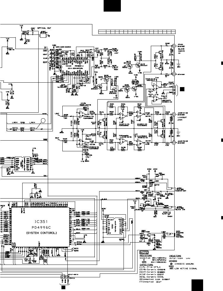
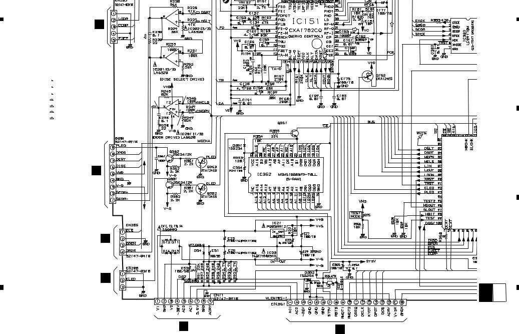
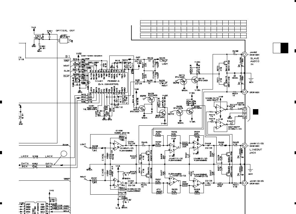
3. SCHEMATIC DIAGRAM
Note : When ordering service parts, be sure to refer to "EXPLODED VIEWS and PARTS LIST" or "PCB PARTS LIST".
A
|
|
|
|
|
|
|
|
Large size |
|
|
|
A-a |
|
|
A-b |
|
|
|
|
|
|
|
|
SCH diagram |
||
|
|
|
A-c |
|
A-d |
|||
|
|
|
|
|
||||
|
|
|
|
|
|
|
|
|
|
|
|
|
|
|
|
|
|
|
|
|
|
|
|
|
|
|
A-a |
A-b |
Guide page |
B |
|
Detailed page |
A-a |
A-b |
|
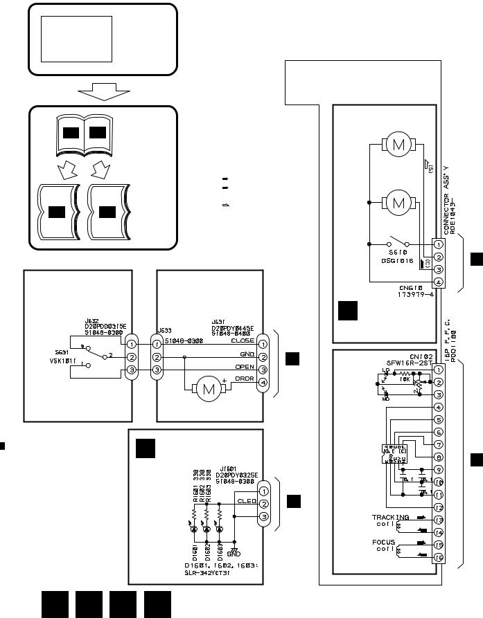
3.1MECHANISM BOARD, DOOR MOTOR BOARD, DOOR SW BOARD, LED BOARD and PICKUP ASSEMBLIES
SERVO MECHANISM ASSY (PXA1591)
SPINDLE
MOTOR
ASSY
PEA1235
SIGNAL ROUTE |
CARRIADGE |
|
(F) |
: FOCUS SERVO LOOP |
MOTOR |
|
||
(T) |
: TRACKING SERVO LOOP |
ASSY |
|
||
(C)
 : CARRIAGE SERVO LOOP
(S)
: SPINDLE DRIVE
PEA1246
|
|
|
|
|
|
|
|
|
|
|
|
|
|
C |
DOOR SW |
B |
DOOR MOTOR |
|
|
|
BOARD ASSY |
|
BOARD ASSY |
|
|
|
|
||
|
|
|
(PWZ3865) |
|
(PWZ3863) |
C 
 K
K
CN205
DOOR MOTOR
VXM1033
D LED BOARD ASSY (PWZ3867)
K
CN208
D
K
CN207
A MECHANISM BOARD ASSY (PWX1192)
PICKUP ASSY (PEA1335)
K
CN202
(T)
(T)
(F)
(F)
10
|
1 |
|
2 |
|
3 |
|
4 |
|
|
|
|
|
|
||||
|
|
|
|
|
|
1 |
|
2 |
|
3 |
|
4 |
|
|
|
|
|
|
PD-F1007
3.2LOADING SW, LOADING BOARD, SENSOR BOARD, RECIEVE BOARD, RADIATE BOARD and SELECT BOARD ASSEMBLIES
A
F LOADINGBOARD
ASSY (PWZ3788)
E LOADING SW ASSY (PWZ3790)
REAF SW
VSK1011
G SENSOR BOARD |
|
ASSY |
|
(PWZ3781) |
1.5k |
|
100k |
100k |
|
150
D20PDY0310E |
J605 |
|
K |
|
|
|
CN203 |
|
|
LOADING MOTOR |
|
B |
|
VXM1033 |
|
||
|
|
||
P |
VOLUME BOARD ASSY |
|
|
|
(PWZ3866) |
H |
RECIEVE |
22k |
|
||
|
|
|
BOARD |
VR601 |
|
ASSY |
|
|
|
|
|
CN605 |
CN604 |
|
(PWZ3792) |
|
|
||
52147–0310 ×2 J604 |
|
|
|
D20PDY0315E
I RADIATEBOARD
ASSY (PWZ3791)
C
K
CN204
SELECT MOTOR
VXM1033
J SELECTBOARD
ASSY (PWZ3785)
D
11
|
1 |
|
2 |
|
3 |
|
4 |
|
|
|
|
|
|
||||
|
|
|
|
|

A
B
C
1 |
|
|
2 |
|
|
3 |
|
4 |
|
|
|
|
|
|
|||||||
PD-F1007 |
|
|
|
|
|
|
|
|
||
|
|
|
|
|
|
|
||||
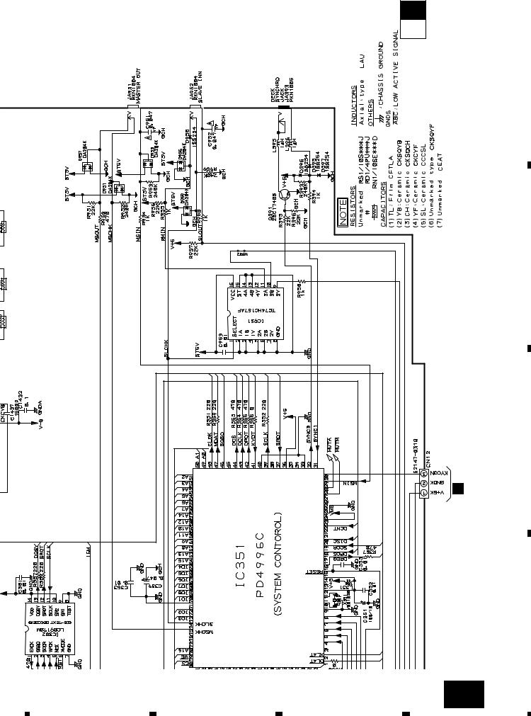
3.3 MAIN BOARD ASSY |
|
K-a |
|
|
|
|||||
CAUTION : FOR CONTINUED PROTECTION AGAINST RISK OF FIRE,
REPLACE ONLY WITH SAME TYPE NO. ICP-N10, MFD BY
ROHM CO., FOR IC35 AND IC36.
|
|
MAIN |
|
|
|
2 23 |
|
|
|
|
K BOARD |
|
|
|
|
|
|
|
|
|
|
3 |
4 |
|
|
|
|
|
ASSY |
|
|
|
|
||
|
|
|
|
|
|
|
||
|
|
(PWZ3823) |
1.8V |
|
|
|
|
|
|
|
|
-0.7V |
|
(S) |
|
|
|
|
|
|
|
(S) |
|
|
|
|
|
|
|
|
1.8V |
(S) |
|
33 |
|
|
|
|
|
7 |
|
|
|
|
|
|
|
|
|
|
|
|
|
|
|
5 |
|
|
|
|
|
|
|
|
|
|
1.6V |
|
|
|
|
CN610 |
|
|
|
|
(F) |
53 |
|
|
|
|
|
(F) |
|
|
|
||
|
|
|
|
0V |
|
|
|
|
A |
|
|
|
1.6V |
|
|
|
|
|
|
|
|
|
|
|
|
|
|
|
|
6 |
|
|
|
|
|
|
|
|
|
1.6V |
|
|
|
|
|
|
|
|
|
(T) |
|
|
|
|
|
|
|
(T) |
|
|
|
|
|
|
|
|
0V |
|
|
|
|
|
|
|
|
1.6V |
|
18 |
|
|
|
|
(F) |
|
|
|
|
|
|
ASSY |
|
(F) |
8 |
|
|
19 |
|
|
|
(F) |
1.7V |
|
16 |
|
|||
|
|
(F) |
|
|
|
|
|
|
PICUPto |
|
|
|
0.2V |
|
|
|
|
|
|
|
|
(C) |
|
(T) (T) |
(F) (F) (F) (F) |
|
|
|
(T) |
|
1.7V |
|
|
|
|
|
|
(T) |
|
|
0V |
|
|
|
|
|
|
0V |
|
|
|
|
|
|
|
|
|
(L) |
|
|
|
|
|
|
|
|
(L) |
|
|
|
|
|
|
|
|
|
(L) |
|
|
|
|
|
|
|
|
0V |
|
|
|
|
|
|
|
|
(SEL) |
|
|
|
|
|
F |
|
|
(SEL) |
|
|
|
|
|
|
|
|
(F) |
|
|
|
|
|
J651 |
|
(SEL) |
|
|
|
|
|
|
|
|
|
|
|
23 |
|
|
|
SIGNAL ROUTE |
|
|
|
|
|
|
|
|
: AUDIO SIGNAL |
|
|
|
|
|
|
|
|
: EFM SIGNAL |
|
|
|
(T) |
|
|
|
(F) |
: FOCUS SERVO LOOP |
|
|
|
|
|
|
|
|
|
|
|
|
|
|
|
|
(T) |
: TRACKING SERVO LOOP |
|
|
|
|
|
|
|
|
|
|
|
|
|
||
|
(C) |
: CARRIAGE SERVO LOOP |
|
0V |
|
|
|
|
|
|
|
|
|
|
|||
|
(S) |
: SPINDLE DRIVE |
|
0V |
(D) |
|
|
|
|
|
|
(C) |
|
|
|||
|
(L) |
: LOADING DRIVE |
|
(D) |
|
|
|
|
|
(D) |
|
|
(D) |
|
|
|
|
|
: DOOR DRIVE |
|
|
|
|
|
||
|
(SEL) |
|
|
|
|
|
|
|
|
: SELECT DRIVE |
|
|
|
|
|
|
|
|
|
|
|
|
|
|
|
|
|
|
|
|
|
0V |
|
2SD2144S |
|
J
J601
|
B |
|
D |
J631 |
|
|
|
|
|
D |
|
|
J1601 |
|
12 |
O J11 |
L J701 |
|
|
|
1 |
|
2 |
|
3 |
|
4 |
|
|
|
|
|
|
||||
|
|
|
|
|
|
5 |
|
6 |
|
7 |
|
8 |
|
|
|
|
|
|
PD-F1007
K-b
IC301(CXD2529Q) :PLAY MODE
PIN No. |
1 |
2 |
3 - 4 |
7 |
8 |
9 |
10 |
11 |
12 |
13 |
14 |
16 |
17 |
23 |
24 |
25 |
Voltage(V) |
5 |
0 |
0 |
4.7 |
1.2-1.3 |
1.2-1.4 |
4.4 |
5 |
4.7 |
4.7 |
0.05 |
5 |
4.7 |
5 |
5 |
0 |
|
|
|
|
|
|
|
|
|
|
|
|
|
|
|
|
|
PIN No. |
26 |
27 |
38 |
39 |
40 |
41 |
42 |
43 |
44 |
45 |
46 |
47 |
48 |
50-55 |
56 |
57 |
Voltage(V) |
5 |
2.6-2.7 |
2.5 |
3.1 |
2.5 |
0 |
3.1 |
5 |
2.5 |
0.9 |
2.5 |
2.5 |
5 |
2.5 |
0 |
5 |
A
PIN No. |
61 |
71 |
75 |
78 |
79 |
82 |
83 |
84-86 |
87 |
88 |
89-90 91-92 93-95 |
96 |
97 |
100 |
||
Voltage(V) |
5 |
2.5 |
0 |
0 |
5 |
0 |
5 |
2.5 |
0 |
5 |
2.5 |
0 |
2.5 |
5 |
0 |
5 |
|
|
|
|
|
|
|
|
|
|
|
|
|
|
|
|
N |
|
|
|
|
|
|
|
|
|
|
|
|
|
|
|
|
J501 |
|
|
|
|
|
|
|
|
|
|
|
|
|
|
|
|
B |
10 |
|
|
|
|
|
|
|
|
|
|
|
|
|
|
|
|
|
|
|
|
|
|
|
|
|
|
|
|
|
|
|
|
C |
|
|
|
|
|
|
|
|
|
|
|
|
|
|
|
|
D |
O J71 |
|
|
|
|
|
|
|
|
|
|
|
|
|
|
|
13 |
|
5 |
|
6 |
|
7 |
|
8 |
|
|
|
|
|
|
||||
|
|
|
|
|

|
D |
|
C |
|
B |
|
A |
|
|
|
|
|
14 |
CAUTION : FOR CONTINUED PROTECTION AGAINST RISK OF FIRE, |
|
a-K |
|
|
REPLACE ONLY WITH SAME TYPE NO. ICP-N10, MFD BY |
|
|
ROHM CO., FOR IC35 AND IC36. |
|
1 |
|
|
MAIN |
|
|
|
|
2 23 |
|
|
|
K BOARD |
|
|
|
|
|
|
|
|
|
|
|
3 |
4 |
|
|
|
|
ASSY |
|
|
|
|
|
||
|
|
|
|
|
|
|
||
|
(PWZ3823) |
1.8V |
|
|
|
|
|
|
|
|
-0.7V |
|
|
(S) |
|
|
|
|
|
|
(S) |
|
|
|
|
|
|
|
|
1.8V |
|
(S) |
|
33 |
|
|
|
|
7 |
|
|
|
|
|
|
|
|
|
|
|
|
|
|
|
5 |
|
|
|
|
|
|
|
2 |
|
|
1.6V |
|
|
|
|
|
CN610 |
|
|
|
(F) |
|
53 |
|
|
|
|
(F) |
|
|
|
|
||
|
|
|
0V |
|
|
|
|
|
A |
|
|
1.6V |
|
|
|
|
|
|
|
|
|
|
|
|
|
|
|
|
6 |
|
|
|
|
|
|
|
|
|
1.6V |
|
|
|
|
|
|
|
|
|
(T) |
|
|
|
|
|
|
|
(T) |
|
|
|
|
|
|
|
|
0V |
|
|
|
|
|
3 |
|
|
1.6V |
|
|
|
|
|
|
|
|
|
|
18 |
|
|
|
|
(F) |
|
|
|
|
|
|
|
ASSY |
(F) |
8 |
|
|
|
19 |
|
|
(F) |
1.7V |
|
|
16 |
|
|||
|
(F) |
|
|
|
|
|
|
|
PICUPto |
|
|
0.2V |
|
|
|
|
|
|
|
|
(C) |
|
|
(T) (T) |
(F) (F) (F) (F) |
|
|
(T) |
|
1.7V |
|
|
|
|
|
|
(T) |
|
|
|
|
0V |
|
|
|
|
0V |
|
|
|
|
|
|
|
|
|
|
|
(L) |
|
|
|
|
|
|
(L) |
|
|
|
|
|
4 |
|
|
|
|
|
(L) |
|
|
|
|
|
|
|
0V |
|
|
|
|
|
|
|
|
|
(SEL) |
|
|
|
F |
|
|
|
|
(SEL) |
|
|
|
|
|
|
|
(F) |
|
|
|
|
J651 |
|
(SEL) |
|
|
|
|
|
1 F1007-PD
K-a K-b
2
3
4
F
J651
5 |
SIGNAL ROUTE |
 : AUDIO SIGNAL
 : EFM SIGNAL
) |
: FOCUS SERVO LOOP |
|||
|
|
|
||
) |
||||
: TRACKING SERVO LOOP |
||||
|
|
|
||
) |
: CARRIAGE SERVO LOOP |
|||
|
|
|
||
) |
: SPINDLE DRIVE |
|||
|
|
|
||
) |
: LOADING DRIVE |
|||
|
) |
|||
|
: DOOR DRIVE |
|||
|
L) |
|||
|
: SELECT DRIVE |
|||
|
|
|
||
6
J
J601
|
|
B |
7 |
||
J631
D
J1601
8 |
a-K |
|
|
|
15 |
(SEL)
(SEL)
(F)
(SEL)
23
(T)
|
0V |
|
0V |
(D) |
(C) |
(D) |
|
|
|
|
|
|
(D) |
|
0V |
|
2SD2144S |
O J11 |
L J701 |
|
5
6
7
K-a K-b
8 F1007-PD
|
D |
|
C |
|
B |
|
A |
|
|
|
|
|
|
|
|
16 |
|
|
|
|
|
|
1 |
b-K |
|
|
|
|
|
|
|
|
|
|
D |
|
C |
|
B |
|
A |
|
|
|
IC301(CXD2529Q) :PLAY MODE
PIN No. |
1 |
2 |
3 - 4 |
7 |
8 |
9 |
10 |
11 |
12 |
13 |
14 |
16 |
17 |
23 |
24 |
25 |
Voltage(V) |
5 |
0 |
0 |
4.7 |
1.2-1.3 1.2-1.4 |
4.4 |
5 |
4.7 |
4.7 |
0.05 |
5 |
4.7 |
5 |
5 |
0 |
|
PIN No. |
26 |
27 |
38 |
39 |
40 |
41 |
42 |
43 |
44 |
45 |
46 |
47 |
48 |
50-55 |
56 |
57 |
Voltage(V) |
5 |
2.6-2.7 |
2.5 |
3.1 |
2.5 |
0 |
3.1 |
5 |
2.5 |
0.9 |
2.5 |
2.5 |
5 |
2.5 |
0 |
5 |
PIN No. |
61 |
71 |
75 |
78 |
79 |
82 |
83 |
84-86 |
87 |
88 |
89-90 91-92 93-95 |
96 |
97 |
100 |
||
Voltage(V) |
5 |
2.5 |
0 |
0 |
5 |
0 |
5 |
2.5 |
0 |
5 |
2.5 |
0 |
2.5 |
5 |
0 |
5 |
1 F1007-PD
K-a K-b
2
3
4
10 |
2
N
J501
3
4
|
5 |
|
6 |
|
7 |
|
8 |
|
|
|
|
|
|
PD-F1007
K-a K-b
A
B
|
|
|
|
C |
|
|
|
J71 |
|
|
|
|
O |
|
|
|
|
|
D |
|
|
|
K-b |
17 |
|
|
|
|
|
5 |
6 |
7 |
8 |
|
 Loading...