


FILE–TYPE |
|
|
|
|
|
|
|
COMPACT DISC PLAYER |
|
|
|
|
|
|
|
×óÀX/.ù |
|
|
ë |
|
|
|
|
|
|
|
MODE |
HI-LITE |
|
|
|
|
|
|
|
|
DISPLAY |
BEST |
PREVIOUS |
|
|
|
CLEAR |
PROGRAM |
TITLE |
|
DISC |
|
|
° |
|
|
INPUT |
|
|
|
|
°@°@ |
' |
|
|
|
|
|
|
°°@@ |
|
|
|
|
|
|
|
°@ FILE –TYME CD MECHANISM |
|
|
|
|
|
SINGLE LOADER |
°@ |
|
|
|
|
|
|
|
|
°@ |
|
|
|
|
|
ACSESS |
PLAY |
°@ |
OPEN/ |
|
6 |
7 |
4 1 Á ¢ |
@ |
UNLOAD |
||||||
|
|
°@ |
CLOSE |
|
|
|
|
|
|
°@ |
|
|
|
|
|
|
|
°@ |
|
|
|
|
|
|
|
° |
|
|
|
|
|
ORDER NO.
RRV2085
FILE-TYPE COMPACT DISC PLAYER
PD-F958
PD-F908
THIS MANUAL IS APPLICABLE TO THE FOLLOWING MODEL(S) AND TYPE(S).
Type |
|
Model |
Power Requirement |
Remarks |
|
|
|
|
|||
PD-F958 |
|
PD-F908 |
|||
|
|
|
|
||
|
|
|
|
|
|
KUXQ |
– |
|
O |
AC120V |
|
|
|
|
|
|
|
KCXQ |
– |
|
O |
AC120V |
|
|
|
|
|
|
|
KUXQ/CA |
O |
|
– |
AC120V |
|
|
|
|
|
|
|
CONTENTS
1. SAFETY INFORMATION .................................... |
2 |
7.2 DIAGNOSIS ................................................ |
39 |
2. EXPLODED VIEWS AND PARTS LIST ............. |
3 |
7.2.1 ERROR CORD DISPLAY ................. |
39 |
3. SCHEMATIC DIAGRAM ................................... |
11 |
7.2.2 ERROR HISTORY AND DISPLAY ... |
39 |
4. PCB CONNECTION DIAGRAM ....................... |
19 |
7.2.3 ERROR HISTORY DISPLAY ............ |
40 |
5. PCB PARTS LIST ............................................. |
24 |
7.2.4 DISASSEMBLY ................................. |
41 |
6. ADJUSTMENT .................................................. |
28 |
7.3 BLOCK DIAGRAM ...................................... |
49 |
7.GENERAL INFORMATION ............................... |
36 |
8. PANEL FACILITIES AND SPECIFICATIONS |
|
7.1 PARTS ........................................................ |
36 |
................................................................... |
50 |
7.1.1 IC .......................................................... |
36 |
|
|
7.1.2 DISPLAY ............................................... |
37 |
|
|
PD-F958, PD-F908
1. SAFETY INFORMATION
This service manual is intended for qualified service technicians; it is not meant for the casual do-it-yourselfer. Qualified technicians have the necessary test equipment and tools, and have been trained to properly and safely repair complex products such as those covered by this manual.
Improperly performed repairs can adversely affect the safety and reliability of the product and may void the warranty. If you are not qualified to perform the repair of this product properly and safely, you should not risk trying to do so and refer the repair to a qualified service technician.
WARNING
This product contains lead in solder and certain electrical parts contain chemicals which are known to the state of California to
cause cancer, birth defects or other reproductive harm.
Health & Safety Code Section 25249.6 – Proposition 65
NOTICE
(FOR CANADIAN MODEL ONLY)
Fuse symbols 
 (fast operating fuse) and/or
  (slow operating fuse) on PCB indicate that replacement parts must be of identical designation.
REMARQUE
(POUR MODÈLE CANADIEN SEULEMENT)
Les symboles de fusible 


 (fusible de type rapide) et/ou

 (fusible de type lent) sur CCI indiquent que les pièces de remplacement doivent avoir la même désignation.
(FOR USA MODEL ONLY)
1. SAFETY PRECAUTIONS
The following check should be performed for the continued protection of the customer and service technician.
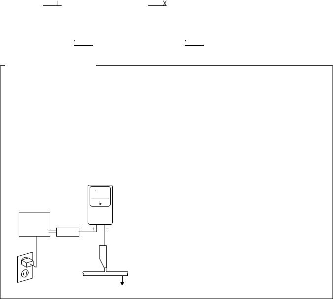
LEAKAGE CURRENT CHECK
Measure leakage current to a known earth ground (water pipe, conduit, etc.) by connecting a leakage current tester such as Simpson Model 229 - 2 or equivalent between the earth ground and all exposed metal parts of the appliance (input/output terminals, screwheads, metal overlays, control shaft, etc.). Plug the AC line cord of the appliance directly into a 120V AC 60 Hz outlet and turn the AC power switch on. Any current measured must not exceed 0.5 mA.
|
Reading should |
|
not be above |
|
Leakage 0.5 mA |
Device |
current |
tester |
|
under |
|
test |
|
|
Test all exposed |
|
metal surfaces |
Also test with plug reversed
(Using AC adapter plug as required)
Earth ground
AC Leakage Test
ANY MEASUREMENTS NOT WITHIN THE LIMITS OUTLINED ABOVE ARE INDICATIVE OF A POTENTIAL SHOCK HAZARD AND MUST BE CORRECTED BEFORE RETURNING THE APPLIANCE TO THE CUSTOMER.
2. PRODUCT SAFETY NOTICE
Many electrical and mechanical parts in the appliance have special safety related characteristics. These are often not evident from visual inspection nor the protection afforded by them necessarily can be obtained by using replacement components rated for voltage, wattage , etc. Replacement parts which have these special safety characteristics are identified in this Service Manual.
Electrical components having such features are identified by marking with a  on the schematics and on the parts list in this Service Manual.
The use of a substitute replacement component which does not have the same safety characteristics as the PIONEER recommended replacement one, shown in the parts list in this Service Manual, may create shock, fire, or other hazards.
Product Safety is continuously under review and new instructions are issued from time to time. For the latest information, always consult the current PIONEER Service Manual. A subscription to, or additional copies of, PIONEER Service Manual may be obtained at a nominal charge from PIONEER.
2
PD-F958, PD-F908
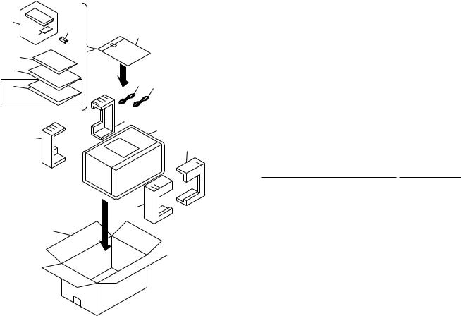
2. EXPLODED VIEWS AND PARTS LIST
NOTES : Ö Parts marked by “ NSP ” are generally unavailable because they are not in our Master Spare Parts List.
ÖThe  mark found on some component parts indicates the importance of the safety factor of the part. Therefore, when replacing, be sure to use parts of identical designation.
ÖScrew adjacent to °mark on the product are used for disassembly.
2.1PACKING
3
13 |
8 |
|
|
|
|
4 |
|
|
|
|
|
5 |
|
|
|
|
|
6 |
|
|
|
|
|
7 |
2 |
1 |
|
|
|
PD-F908/KCXQ only |
10(2/2) |
|
|
|
|
|
|
|
|
|
|
|
|
12 |
|
|
|
10(1/2) |
|
9(2/2) |
|
|
|
|
|
|
|
|
|
|
|
(1) PARTS LIST |
|
||
|
Front |
Mark No. |
Description |
Part No. |
|
|
|
|
1 |
Control Cable (L=1.0m) |
PDE1247 |
|
|
|
2 |
Output Cable (L=1.0m) |
PDE1248 |
|
9(1/2) |
|
3 |
Remote Control Unit |
See Contrast table (2) |
|
|
4 |
Battery Cover |
PZN1105 |
|
|
|
|
|||
|
|
NSP |
5 |
Warranty Card |
See Contrast table (2) |
11 |
|
|
|
|
|
|
|
|
6 |
Operating Instructions (English) |
See Contrast table (2) |
|
|
|
7 |
Operating Instructions (French)) |
See Contrast table (2) |
|
|
|
8 |
Polyethlene Bag |
Z21 - 038 |
|
|
|
9 |
Styrol Protector F |
PHA1333 |
|
|
|
10 |
Styrol Protector R |
PHA1334 |
|
|
|
11 |
Packing Case |
See Contrast table (2) |
|
|
|
12 |
Mirror Mat |
PHF1001 |
|
|
NSP |
13 |
Battery (R6P, AA) |
VEM 1010 |
(2) CONTRAST TABLE
PD-F908/KUXQ,KCXQ and PD-F958/KUXQ/CA have the same construction except for the following:
|
|
|
|
Part No. |
|
|
Mark |
No. |
Symbol & Description |
PD-F958/ |
PD-F908/ |
PD-F908/ |
Remarks |
|
|
|
KUXQ/CA |
KUXQ |
KCXQ |
|
|
|
|
|
|
|
|
|
3 |
Remote Control Unit |
PWW1148 |
PWW1147 |
PWW1147 |
|
|
|
|
(CU-PD101) |
(CU-PD100) |
(CU-PD100) |
|
NSP |
5 |
Warranty Card |
ARY7023 |
ARY7023 |
ARY7024 |
|
|
6 |
Operating Instructions (English) |
PRB1278 |
PRB1277 |
PRB1277 |
|
|
7 |
Operating Instructions (French) |
Not used |
Not used |
PRD1034 |
|
|
11 |
Packing Case |
PHG2337 |
PHG2334 |
PHG2335 |
|
|
|
|
|
|
|
|
3

PD-F958, PD-F908
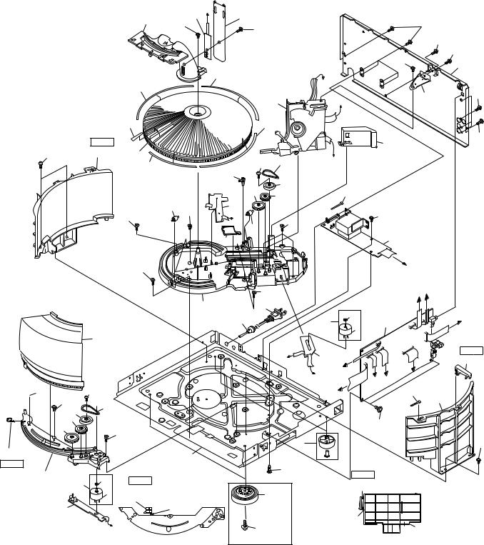
2.2 EXTERIOR
57
62
55 KUXQ/CA,KUXQ type only
44 (A)
50
46
63
13 
60
PD-F908 only
47
 61
61
51
58
53
 62
62
68
4
68
44 (B)
|
44 (C) |
A |
|
|
|
||
|
|
11 |
|
|
|
3 |
|
|
No.44(A) |
Cutting |
|
|
Power button |
||
63 |
|
Note Cutting position |
|
|
No.44(Function button) |
||
|
|
||
13 |
No.44(B) |
|
|
|
|
||
PD-F908 only |
Single loader |
|
|
button |
Cutting |
||
|
|||
|
|
No.44(C) |
|
|
|
Function button |
4
PD-F958, PD-F908
63
 15
15
63
30 28
29
26(2/2)
Note2
26(1/2)
25
5
|
|
6 |
D |
|
24 |
|
|
|
|
|
|
|
27 |
|
|
|
|
|
|
|
|
||
|
65 |
|
|
|
|
|
|
|
61 |
|
|
|
|
|
|
67 |
|
|
|
|
|||
|
|
|
|
|
|
|
|
|
|
||
|
|
|
|
|
|
|
|
|
|
61 |
|
|
|
|
|
|
|
|
|
|
|
|
61 |
|
|
|
|
|
|
Refer to |
|
16 |
|
18 |
|
|
|
|
32(3/4) |
|
|
|
|
||||
|
|
|
|
''2.3 LOADING |
J |
|
|
|
|||
|
32(4/4) |
|
|
|
|
MECHANISM |
|
|
61 |
||
|
|
|
|
|
|
ASSY'' |
F |
|
19 |
||
|
|
|
|
|
|
|
31 |
|
|
|
|
|
56 |
|
|
|
|
32(2/4) |
|
|
|
|
|
Note1 |
|
|
|
|
|
|
|
|
41 |
|
66 |
|
|
|
|
|
|
|
|
|
|
||
21(1/2) |
35 |
|
|
|
|
|
33 |
E |
|
|
|
|
32(1/4) |
|
|
|
64 |
|
|
|
|||
|
|
|
|
|
|
|
|
|
|||
|
|
|
|
40 |
|
|
43 |
|
|
|
|
|
|
|
|
|
|
|
|
|
|
|
|
|
|
|
|
|
38 |
37 |
69 |
|
|
|
|
|
|
|
|
8 |
|
|
|
|
|
||
|
|
42 |
|
|
|
|
|
|
|
||
|
|
|
|
|
|
|
|
|
|
|
|
|
15 |
63 |
|
|
H |
|
|
|
63 |
|
|
|
|
|
|
|
15 |
|
|
|
|||
|
|
|
|
|
42 |
|
|
|
|
|
|
|
|
|
|
|
|
|
|
|
|
|
|
|
|
|
|
39 |
|
|
|
|
2 |
|
|
|
15 |
|
|
|
|
|
|
|
G |
|
|
|
|
|
|
|
|
15 |
|
|
E J |
|
|
|
|
|
36 |
|
|
12 |
|
34 |
|
|
|
|
|
|
|
|
10 |
|
|
1 |
|
F |
|
|
|
|
|
|
|
|
25 |
|
|||
|
|
|
|
|
|
|
|
59 |
|
|
|
52 |
|
|
|
|
|
|
|
|
|
|
|
|
|
|
|
|
|
|
H |
7 |
|
|
Note1 |
|
|
|
|
|
|
|
|
|
21 (2/2) |
||
|
|
|
|
|
|
|
|
D |
G |
|
|
|
|
|
|
|
|
|
|
C |
|
|
|
|
|
|
|
|
|
|
|
B C |
|
|
|
64 |
|
|
|
|
|
|
|
A |
69 |
21(1/2) |
|
|
|
|
|
|
|
|
|
|
|
||
23 |
|
|
|
|
|
|
|
|
|
|
|
|
|
|
|
|
|
|
|
|
63 |
|
|
|
15 |
|
|
|
|
|
|
|
|
|
|
|
|
|
|
|
|
|
14 |
|
|
|
63 |
|
|
17 |
|
|
|
|
|
|
|
|
|
|
|
|
|
|
|
|
22 |
Note1 cutting position |
|
||
34 |
Note2 cutting position |
|
|
|
|
|
|||||
|
|
|
|
cutting |
No.21(Back Fence) |
|
|||||
59 |
|
No.26(Hood Base) |
|
|
20 |
|
|||||
26(2/2) |
|
|
|
|
|
|
|||||
|
|
|
|
|
21(2/2) |
|
|
|
|||
|
|
|
|
|
|
|
|
|
|
||
|
|
cutting |
|
|
|
|
|
|
|
|
|
|
|
|
|
|
|
|
|
|
|
|
|
B |
|
|
|
|
|
|
cutting |
|
|
|
|
|
|
|
|
60 |
|
|
|
21(1/2) |
|
||
|
|
26(1/2) |
|
|
PD-F958 Only |
|
|
|
|
||
|
|
|
|
|
|
|
|
|
|
|
|
5

PD-F958, PD-F908
(1) EXTERIOR PARTS LIST
Mark |
No. |
|
Description |
|
Part No. |
|
|
|
|
|
|
|
|
|
|
|
|
|
|
|
|
|
1 |
Main Board Assy |
|
See Contrast table(2) |
|
|
|
2 |
Power Board Assy |
|
See Contrast table(2) |
|
|
|
3 |
Display Board Assy |
|
See Contrast table(2) |
|
NSP |
4 |
Switch Board Assy |
|
See Contrast table(2) |
||
NSP |
5 |
Door Board Assy |
|
See Contrast table(2) |
||
NSP |
6 |
Center LED Board Assy |
|
See Contrast table(2) |
||
NSP |
7 |
Select Motor Board Assy |
|
PWZ3324 |
||
NSP |
8 |
Sensor Board Assy |
|
PWZ3327 |
||
|
|
9 ............. |
|
|
||
|
|
10 |
Cord Stopper |
|
CM - 22C |
|
|
|
11 |
F.F.C/30V |
|
See Contrast table(2) |
|
|
|
12 |
AC Power Cord |
|
PDG1064 |
|
|
|
13 |
Rubber Sheet |
|
See Contrast table(2) |
|
|
|
14 |
Foot Assy |
|
REC1263 |
|
|
|
15 |
Screw C |
|
PBA1106 |
|
|
|
16 |
Screw |
|
PBA1108 |
|
NSP |
17 |
Under Base |
|
PNA2255 |
||
|
|
18 |
Rear Base |
|
See Contrast table(2) |
|
|
|
19 |
Stopper Angle |
|
PNB1559 |
|
|
|
20 |
Insulator |
|
See Contrast table(2) |
|
|
|
21 |
Back Fence |
|
PNW2671 |
|
|
|
22 |
Locking Card Spacer |
|
VEC1596 |
|
|
|
23 |
Belt |
|
PEB1288 |
|
|
|
24 |
Cover |
|
PNM1294 |
|
|
|
25 |
Motor Assy |
|
PEA1333 |
|
|
|
26 |
Hood Base |
|
PNW2633 |
|
|
|
27 |
Center Pole |
|
PNW2634 |
|
|
|
28 |
Gear (Middle) |
|
PNW2906 |
|
|
|
29 |
Gear (Twin) |
|
PNW2642 |
|
|
|
30 |
Gear Pulley |
|
VNL1662 |
|
|
|
31 |
Loading Mechanism Assy |
|
PXA1589 |
|
|
|
32 |
Rack Label |
|
PAM1783 |
|
|
|
33 |
Belt |
|
PEB1288 |
|
|
|
34 |
Motor Pulley |
|
PNW1634 |
|
|
|
35 |
Disc Rack |
|
PNW2845 |
|
Mark No. |
|
Description |
|
Part No. |
||
|
|
|
|
|
|
|
|
|
|
|
|
|
|
36 |
Mecha Base |
|
PNW2639 |
|||
37 |
Gear |
|
PNW2906 |
|||
38 |
Gear |
|
PNW2642 |
|||
39 |
Slider |
|
PNW2643 |
|||
40 |
Lock Lever |
|
PNW2644 |
|||
41 |
Mecha Stopper |
|
PNW2646 |
|||
42 |
Roller |
|
PNW2647 |
|||
43 |
Gear Pulley |
|
VNL1662 |
|||
44 |
Function Button |
|
See Contrast table(2) |
|||
45 ............. |
|
|
||||
46 |
Name Plate |
|
PAM1776 |
|||
47 |
Display Window |
|
See Contrast table(2) |
|||
48 ............. |
|
|
||||
49 ............. |
|
|
||||
50 |
Operation Panel |
|
See Contrast table(2) |
|||
51 |
Bonnet Case |
|
PYY1191 |
|||
52 |
Hood |
|
PNW2865 |
|||
53 |
Side Cover |
|
PNM1322 |
|||
54 ............. |
|
|
||||
55 |
65 Label |
|
See Contrast table (2) |
|||
56 |
Label |
|
PRW1520 |
|||
57 |
Label |
|
PRW1523 |
|||
58 |
Rivet |
|
RBM-003 |
|||
59 |
Slider Motor |
|
VXM1033 |
|||
60 |
Screw |
|
IBZ30P080FZK |
|||
61 |
Screw |
|
BBZ30P080FZK |
|||
62 |
Screw |
|
FBT40P080FZK |
|||
63 |
Screw |
|
IBZ30P060FMC |
|||
64 |
Screw |
|
IPZ20P080FMC |
|||
65 |
Screw |
|
IPZ30P080FCU |
|||
66 |
Screw |
|
PMZ30P060FZK |
|||
67 |
Screw |
|
PPZ30P050FMC |
|||
68 |
Screw |
|
PPZ30P100FMC |
|||
69 |
Binder |
|
ZCA-SKB90BK |
|||
6

PD-F958, PD-F908
(2) CONTRAST TABLE
PD-F908/KUXQ,KCXQ and PD-F958/KUXQ/CA have the same construction except for the following:
|
|
|
|
|
Part No. |
|
|
Mark |
No. |
|
Symbol & Description |
PD-F958/ |
PD-F908/ |
PD-F908/ |
Remarks |
|
|
|
|
KUXQ/CA |
KUXQ |
KCXQ |
|
|
|
|
|
|
|
|
|
|
1 |
|
Main Board Assy |
PWZ3895 |
PWZ3876 |
PWZ3876 |
|
|
2 |
|
Power Board Assy |
PWZ3900 |
PWZ3879 |
PWZ3879 |
|
|
3 |
|
Display Board Assy |
PWZ3904 |
PWZ3882 |
PWZ3882 |
|
NSP |
4 |
|
Switch Board Assy |
PWZ3907 |
PWZ3885 |
PWZ3885 |
|
NSP |
5 |
|
Door Board Assy |
PWZ3913 |
PWZ3890 |
PWZ3890 |
|
NSP |
6 |
|
Center LED Board Assy |
PWZ3915 |
PWZ3892 |
PWZ3892 |
|
|
11 |
|
F.F.C/30V |
PDD1186 |
PDD1167 |
PDD1167 |
|
|
|
|
|
(40P F.F.C) |
(32P F.F.C) |
(32P F.F.C) |
|
|
13 |
|
Rubber Sheet |
Not Used |
AEB1111 |
AEB1111 |
|
|
18 |
|
Rear Base |
PNA2452 |
PNA2450 |
PNA2450 |
|
|
20 |
|
Insulator |
PNW2766 |
Not Used |
Not Used |
|
|
44 |
|
Function Button |
PAC1908 |
PAC1905 |
PAC1905 |
|
|
47 |
|
Display Window |
PAM1772 |
PAM1774 |
PAM1774 |
|
|
50 |
|
Operation panel |
PNW2869 |
PNW2867 |
PNW2867 |
|
|
55 |
|
65 Label |
ORW1069 |
ORW1069 |
Not used |
|
|
|
|
|
|
|
|
|
7
PD-F958, PD-F908
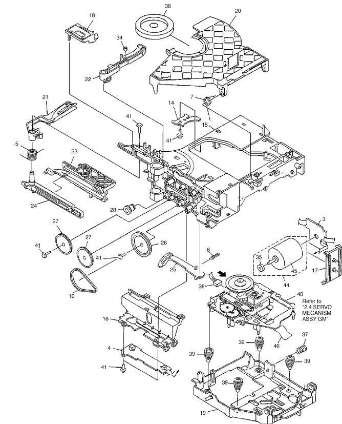
2.3 LOADING MECHANISM ASSY
8

PD-F958, PD-F908

 LOADING MECHANISM ASSY PARTS LIST
Mark No. Description |
Part No. |
|||
|
|
|
|
|
1…………
2…………
NSP |
3 |
Loading Motor Board Assy |
PWZ3337 |
NSP |
4 |
Load SW Board Assy |
PWZ3334 |
|
5 |
Arm A Spring2 |
ABH7124 |
|
6 |
Gear Plate Spring |
ABH7051 |
|
7 |
Clamp Spring |
ABH7107 |
8…………
9…………
10 Loading Belt |
AEB7029 |
11…………
12…………
13…………
NSP 14 |
Servo Stopper S |
ANB7047 |
15 |
Loading Base |
ANW7086 |
16 |
Cam Cover |
ANW7052 |
17 |
Motor Holder |
ANW7053 |
18 |
Sensor Holder |
ANW7119 |
19 |
Float Base 96 |
PNW2700 |
20 |
Clamper Holder |
ANW7117 |
21 |
Arm A2 |
ANW7128 |
22 |
Arm (B) |
ANW7058 |
23 |
Drive Plate |
ANW7059 |
24 |
Arm Plate |
ANW7060 |
25 |
Gear Plate |
ANW7111 |
26 |
Gear Pulley (B) |
ANW7062 |
27 |
Gear A |
ANW7063 |
28 |
Drive Gear |
ANW7064 |
29…………
30…………
31…………
32…………
33…………
34 |
Roller B |
ANW7075 |
35 |
Motor Pulley |
PNW1634 |
36 |
Clamper |
PNW2743 |
37 |
Float Spring |
ABH7049 |
38 |
Connector Assy (4P) |
RDE1043 |
39 |
Float Rubber |
AEB7028 |
NSP 40 |
Servo Mechanism Assy GM |
PXA1591 |
41 |
Screw |
IPZ20P080FMC |
42…………
43…………
44 |
Motor Assy |
AEA7006 |
45 |
Loading Motor |
VXM1034 |
46 |
16P FFC/30V |
PDD1180 |
|
Froil (for Service) |
GYA1001 |
|
Ha Narl (for Service) |
GEM1016 |
9
PD-F958, PD-F908
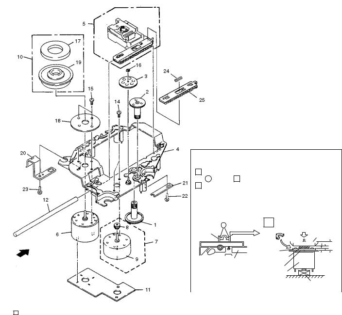
2.4 SERVO MECHANISM ASSY GM
 How to Install the Disc Table
1 Use nipper or other tool to cut the three sections marked A in figure 1 . Then remove the spacer
2 While supporting the spindle motor shaft with the stopper, put spacer on top of the yoke M, and stick the disc table on top (takes about 9kg pressure). Detach the spacer.
|
|
|
|
|
|
|
|
|
|
1 |
|
A |
2 |
(Pressure of about 9 kg) |
||||||||||||||||
|
|
|
|
|
|
|
|
|
|
|
|
Spacer |
|
|
||||||||||||||||
|
|
|
|
|
|
|
|
|
|
|
|
|
Spacer |
|
|
|
|
|
|
|
|
|
|
Disc Table |
||||||
|
|
|
|
|
|
|
|
|
|
|
|
|
|
|
|
|
|
|
|
|
|
|
|
|
||||||
|
|
|
|
|
|
|
|
|
|
|
|
|
|
|
Yoke M |
|
|
|
|
|
|
|
|
|
|
|
|
|
|
6.9mm |
|
|
|
|
|
|
|
|
|
|
|
|
|
|
|
|
|
|
|
|
|
|
|
|
|
|
|
|
|
||
|
|
|
|
|
|
|
|
|
|
|
|
|
|
|
Spacer Setting |
|
|
|
|
|
|
|
|
|
|
|
|
|
|
|
|
|
|
|
|
|
|
|
|
|
|
|
|
|
|
|
|
|
|
|
|
|
|
|
|
|
0.9mm |
||||
|
|
|
|
|
|
|
|
|
|
|
|
|
|
Float Base |
Position |
|
|
|
|
|
|
|
|
|
|
|
|
|||
|
|
|
|
|
|
|
|
|
|
|
|
|
|
|
|
|
|
|
|
|
|
|
|
|
|
±0.05mm |
||||
|
|
|
|
|
|
|
|
|
|
|
|
|
|
|
Carriage Base |
|
|
|
|
|
|
|
|
|
|
1.2mm |
||||
|
|
|
|
|
|
|
|
|
|
|
|
|
|
|
Spindle Motor |
|
|
|
|
|
|
|
|
|
|
|
|
|
|
|
|
|
|
|
|
|
|
|
|
|
|
|
|
|
|
|
|
|
|
|
|
|
|
|
|
|
Stopper |
||||
|
|
|
|
|
|
|
|
|
|
|
|
|
|
|
|
|
|
|
|
|
|
|
||||||||
|
SERVO MECHANISM ASSY GM PARTS LIST |
|
|
|
|
|
|
|
|
|
|
|
|
|
|
|
|
|
||||||||||||
|
|
|
|
|
|
|
|
|
|
|
|
|
|
|
|
|
|
|||||||||||||
|
|
|
|
|
|
|
|
|
|
|
|
|
|
|
|
|
|
|||||||||||||
Mark No. |
Description |
Part No. |
|
Mark No. |
Description |
|
|
|
|
Part No. |
||||||||||||||||||||
|
|
|
|
|
|
|
|
|
|
|
|
|
|
|
|
|
|
|
|
|
|
|
|
|
|
|
|
|
|
|
1 |
Gear 1 |
PNW2052 |
|
|
|
13 |
………… |
|
|
|
|
|
|
|
|
|
|
|
|
|
|
|
|
|||||||
2 |
Gear 2 |
PNW2053 |
|
|
|
14 |
Screw |
|
|
|
|
JFZ17P025FZK |
||||||||||||||||||
3 |
Gear 3 |
PNW2054 |
|
|
|
15 |
Screw |
|
|
|
|
JFZ20P040FMC |
||||||||||||||||||
4 |
Carriage Base |
PNW2699 |
|
|
|
16 |
Washer |
|
|
|
|
WT12D032D025 |
||||||||||||||||||
5 |
Pickup Assy - S |
PEA1335 |
|
|
|
|
|
|
|
|||||||||||||||||||||
|
|
|
|
|
|
|
|
|
|
17 |
Clamp Magnet |
|
|
|
|
PMF1014 |
||||||||||||||
6 |
D.C. Motor Assy (SPINDLE) |
PEA1235 |
|
|
|
18 |
Yoke M |
|
|
|
|
PNB1312 |
||||||||||||||||||
7 |
Carriage DC Motor Assy |
PEA1246 |
|
NSP |
19 |
Disc Table |
|
|
|
|
PNW2410 |
|||||||||||||||||||
8 |
Pinion Gear |
PNW2055 |
|
NSP |
20 |
Float Angle |
|
|
|
|
ANB7020 |
|||||||||||||||||||
9 |
Carriage DC Motor/0.3W |
PXM1027 |
|
|
|
21 |
Gear Stopper |
|
|
|
|
PNB1303 |
||||||||||||||||||
10 |
Disc Table Assy |
PEA1314 |
|
|
|
|
|
|
|
|||||||||||||||||||||
|
|
|
|
|
|
|
|
|
|
22 |
Screw |
|
|
|
|
BPZ20P060FMC |
||||||||||||||
11 |
Mechanism Board Assy |
PWX1192 |
|
|
|
23 |
Screw |
|
|
|
|
BPZ26P100FMC |
||||||||||||||||||
12 |
Guide Bar |
PLA1094 |
|
|
|
24 |
PU Rack Spring |
|
|
|
|
ABH7077 |
||||||||||||||||||
|
|
|
|
|
|
|
|
|
|
25 |
Rack Holder |
|
|
|
|
PNW2056 |
||||||||||||||
10
|
1 |
|
2 |
|
3 |
|
4 |
|
|
|
|
|
|
PD-F958, PD-F908
3. SCHEMATIC DIAGRAM
Note: When ordering service parts, be sure to refer to "EXPLODED VIEW AND PARTS LIST" or "PCB PARTS LIST".
3.1 MECHANISM BOARD ASSY,SENSOR BOARD ASSY,LOAD SW BOARD ASSY,SELECT |
|
MOTOR BOARD ASSY,LOADING MOTOR BOARD ASSY,CENTER LED BOARD ASSY, |
|
DOOR BOARD ASSY and PICKUP ASSY |
A |
SPINDLE MOTOR ASSY PEA1235
A
MECHANISM ASSY GM |
(PXA1591) |
SERVO |
|
CARRIAGE |
|
|
MOTOR |
|
CN610 173979-4 |
ASSY |
|
|
PEA1246 |
MECHANISM |
|
|
||
|
A (PWX1192) |
|
|
BOARD ASSY |
|
PICK UP ASSY (PEA1335)
B
B
LOAD SW BOARD
B ASSY (PWZ3334 )
|
|
|
|
C |
LOADING MECHA |
|
LOADING MOTOR |
|
|
BOARD ASSY |
C |
BOARD ASSY |
|
|
(PWX1474) |
(PWZ3337) |
|
||
|
|
|
||
SENSOR BOARD |
|
SELECT MECHA |
C |
|
|
BOARD ASSY |
|
||
ASSY |
|
(PWX1465) |
|
|
D (PWZ3327) |
|
|
SELECT MOTOR |
|
|
|
E |
|
|
|
|
BOARD ASSY |
|
|
|
|
(PWZ3324) |
|
|
D
CENTER LED BOARD ASSY
PD-F958/KU/CA:(PWZ3915) PD-F908/KU,KC:(PWZ3892)
E
D
F
DOOR BOARD ASSY PD-F958/KU/CA:(PWZ3913) PD-F908/KU,KC:(PWZ3890)
F
G
A B C D E F G 11
|
1 |
|
2 |
|
3 |
|
4 |
|
|
|
|
|
|
||||
|
|
|
|
|

|
1 |
|
2 |
|
3 |
|
4 |
|
|
|
|
|
|
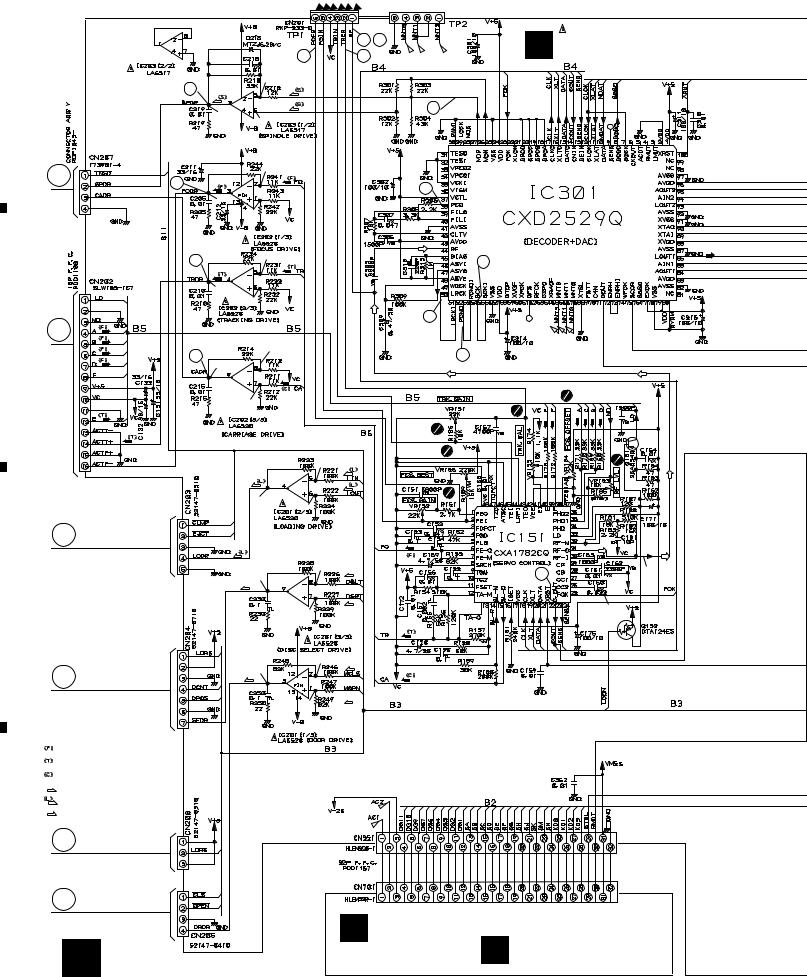
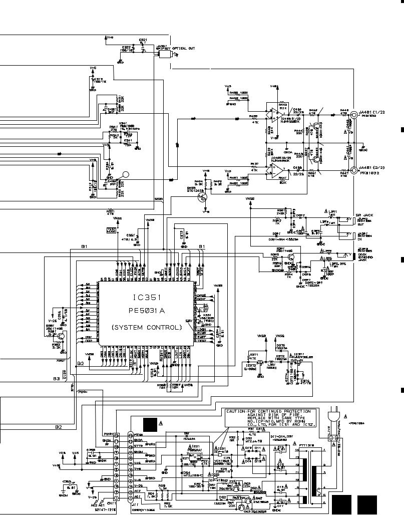
PD-F958, PD-F908
3.2 MAIN BOARD ASSY and POWER BOARD ASSY (FOR PD-F958)
|
|
|
|
|
|
|
|
2 |
23 |
|
|
|
|
|
|
|
|
|
3 |
|
4 |
|
|
|
|
A |
|
|
|
7 |
|
1.8V |
|
|
|
|
|
|
|
|
|
|
|
|
|
|
|
|
|
|
|
|
|
|
|
|
-O.7V |
|
|
|
33 |
|
|
|
|
|
|
|
|
1.8V |
|
|
|
|
|
|
|
|
|
|
|
|
|
|
|
|
|
|
|
|
|
|
A |
|
|
|
1.6V |
|
|
|
|
|
|
|
|
5 |
|
|
|
|
|
53 |
|
|
|
|
|
|
|
|
|
|
|
|
|
|
|
||
|
|
|
|
|
|
|
|
|
|
|
|
|
|
|
|
|
|
OV |
|
|
|
|
|
|
|
|
|
|
|
|
|
1.6V |
|
|
|
|
|
|
|
|
|
|
6 |
|
1.6V |
|
|
|
|
|
|
|
|
|
|
|
|
|
|
16 |
|
|
|
|
|
|
|
|
|
|
|
|
|
|
|
|
|
|
|
|
|
|
OV |
|
|
|
|
|
|
|
|
|
|
|
|
|
1.6V |
|
|
|
|
|
|
|
|
B |
|
|
|
|
|
|
18 |
|
|
|
B |
|
|
|
|
|
|
|
|
|
|
|
|
|
|
|
|
|
1.7V |
|
|
|
|
|
|
|
|
|
|
|
8 |
|
|
|
19 |
|
|
|
|
|
|
|
|
0.2V |
|
|
|
|
|
|
||
|
|
|
|
|
|
|
|
|
|
|
|
|
|
|
|
|
|
|
1.7V |
|
|
|
|
|
|
|
|
|
|
|
|
|
|
|
(T) |
(T) |
(F) |
(F) (F) (F) |
|
|
|
|
|
|
|
0V |
|
|
|
|
|
|
|
|
|
|
|
0V |
|
|
|
|
|
|
|
|
|
|
|
|
0V |
|
|
|
|
|
|
|
|
C |
|
|
|
|
|
|
|
|
|
|
|
|
|
|
|
|
|
0V |
(SEL) |
23 |
|
|
3.4V |
|
|
|
|
|
|
0V |
|
|
|
|||
|
|
|
|
|
|
|
|
|
|
|
||
|
|
|
|
|
|
(SEL) |
|
|
|
|
|
|
C |
|
|
|
|
|
|
|
|
|
|
|
5.0V |
|
|
|
|
|
|
0V |
|
(SEL) |
|
|
|
|
|
|
|
|
|
|
|
|
|
|
|
||
|
|
|
|
|
|
|
|
|
|
|
|
|
|
|
|
|
|
|
|
0V |
(D) |
|
|
|
|
|
|
|
|
|
|
0V |
|
|
|
|
|
|
|
|
D |
|
|
|
|
|
|
|
|
|
|
|
|
|
|
|
(D) |
|
|
|
|
|
|
|
|
|
|
|
|
|
|
|
|
|
|
|
|
|
|
|
|
|
|
|
|
(D) |
|
|
|
|
|
|
|
|
|
|
0V |
|
|
|
|
|
|
|
SIGNAL ROUTE |
|
|
|
|
|
|
|
|
|
|
|
|
|
: AUDIO SIGNAL |
|
|
|
|
|
|
|
|
|
|
|
|
: EFM SIGNAL |
|
|
|
|
|
|
|
|
|
|
|
|
: FOCUS SERVO LOOP |
|
|
|
|
|
|
|
|
|
B12 |
|
|
: TRACKING SERVO LOOP |
|
|
|
|
|
|
|
|
||
|
|
|
|
|
|
|
|
|
|
|
||
|
|
: CARRIAGE SERVO LOOP |
|
|
|
|
|
|
|
|
|
|
|
(S) |
: SPINDLE DRIVE |
|
|
|
|
|
|
|
|
|
|
|
|
|
|
|
|
|
|
|
|
|
|
|
|
(D) |
: LOADING DRIVE |
|
|
|
|
|
|
|
|
|
|
|
: DOOR DRIVE |
|
|
|
|
|
|
|
|
|
|
|
|
|
|
|
|
|
|
|
|
|
|
|
|
E
D
F
|
L |
DISPLAY BOARD ASSY |
12 H |
(PWZ3904) |
|
M |
SWITCH BOARD ASSY |
|
(PWZ3907) |
|
1 |
|
2 |
|
3 |
|
4 |
|
|
|
|
|
|
||||
|
|
|
|
|
5 |
6 |
|
|
|
|
|
|
|
|
7 |
|
|
|
|
|
8 |
|
|
|
|
|
|
|
|
|
|
|
|
|
|
|
PD-F958, PD-F908 |
|
||
IC301(CXD2529Q) :PLAY MODE |
|
|
|
|
|
|
|
|
|
|
|
|
|
|
|||
PIN No. |
1 |
2 |
3 - 4 |
7 |
8 |
9 |
10 |
11 |
12 |
13 |
14 |
16 |
17 |
23 |
24 |
25 |
|
Voltage(V) |
5 |
0 |
0 |
4.7 |
1.2-1.3 1.2-1.4 |
4.4 |
5 |
4.7 |
4.7 |
0.05 |
5 |
4.7 |
5 |
5 |
0 |
|
|
PIN No. |
26 |
27 |
38 |
39 |
40 |
41 |
42 |
43 |
44 |
45 |
46 |
47 |
48 |
50-55 |
56 |
57 |
|
Voltage(V) |
5 |
2.6-2.7 |
2.5 |
3.1 |
2.5 |
0 |
3.1 |
5 |
2.5 |
0.9 |
2.5 |
2.5 |
5 |
2.5 |
0 |
5 |
|
PIN No. |
61 |
71 |
75 |
78 |
79 |
82 |
83 |
84-86 |
87 |
88 |
89-90 91-92 93-95 |
96 |
97 |
100 |
|
||
Voltage(V) |
5 |
2.5 |
0 |
0 |
5 |
0 |
5 |
2.5 |
0 |
5 |
2.5 |
0 |
2.5 |
5 |
0 |
5 |
A |
|
|
|
|
|
|
|
|
|
|
|
|
|
|
|
|
|
|
0V 0V
1.6V
-9.2 |
LINE OUT |
|
JACK |
||
|
0V
|
-9.2 |
1.6V |
|
10 |
0V |
0V |
B
|
|
(UNIT : Ω ) |
|
|
|
(UNIT : μF) |
C |
|
|
|
|
H |
|
(UNIT : μH) |
|
MAIN BOARD ASSY |
|
B1 |
|
|
|
|
|
(PWZ3895) |
|
|
|
|
|
AC120V |
|
|
|
60Hz |
|
|
|
AC POWER CORD |
|
|
B12 |
:PDG1064 |
|
|
|
|
I |
POWER BOARD ASSY |
(PWZ3900) |
D
P0WER TRANSFORMER H I 13
|
5 |
|
6 |
|
7 |
|
8 |
|
|
|
|
|
|
||||
|
|
|
|
|
|
1 |
|
2 |
|
3 |
|
4 |
|
|
|
|
|
|
PD-F958, PD-F908
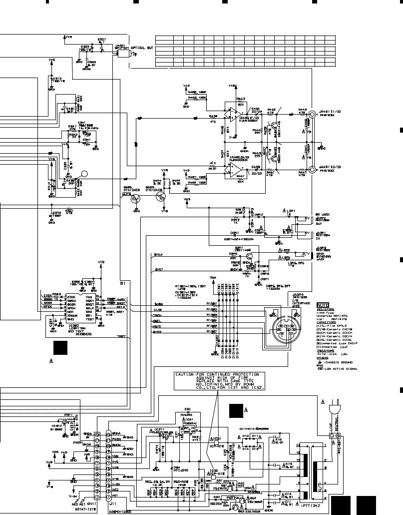
3.3 MAIN BOARD ASSY and POWER BOARD ASSY (FOR PD-F908)
A
B
C
|
|
|
|
|
2 |
23 |
J |
|
MAIN BOARD ASSY |
|
|
|
3 |
|
4 |
|
|
(PWZ3876) |
|
|
7 |
|
1.8V |
|
|
|
|
|
|
|
|
|
|
|
|
|
|
|
|
|
|
-O.7V |
|
|
|
|
33 |
|
|
|
|
1.8V |
|
|
|
|
|
|
|
|
|
|
|
|
|
|
|
|
|
A |
|
|
1.6V |
|
|
|
|
|
|
5 |
|
|
|
|
|
53 |
|
|
|
|
|
|
|
|
|
|
|
||
|
|
|
|
|
|
|
|
|
|
|
|
OV |
|
|
|
|
|
|
|
|
|
|
1.6V |
|
|
|
|
|
|
|
6 |
|
1.6V |
|
|
|
16 |
|
|
|
|
|
|
|
|
|
|
||
|
|
OV |
|
|
|
|
|
|
|
|
|
|
1.6V |
|
|
|
|
|
|
B |
|
|
|
|
|
|
18 |
|
|
|
|
|
|
|
|
|
|
|
|
|
8 |
|
1.7V |
|
|
|
19 |
|
|
|
0.2V |
|
|
|
|
|
|
||
|
|
|
|
|
|
|
|
|
|
|
|
|
1.7V |
|
|
|
|
|
|
|
|
|
|
|
|
|
(T) |
(T) |
(F) (F) (F) (F) |
|
|
B3 |
|
|
|
|
|
|
|
|
|
|
|
0V |
|
|
|
|
|
|
|
|
0V |
|
|
|
|
|
|
|
|
|
0V |
|
|
|
|
|
|
C |
|
|
|
|
|
|
|
|
|
|
|
|
|
0V |
(SEL) |
|
23 |
|
3.4V |
|
|
|
0V |
|
|
|
|||
|
|
|
|
|
|
|
|
||
|
|
|
(SEL) |
|
|
|
|
|
|
|
|
|
0V |
|
(SEL) |
|
|
|
5.0V |
|
|
|
|
|
|
|
|
||
|
|
|
|
|
|
|
|
|
|
|
|
|
|
0V |
(D) |
|
|
|
|
|
|
|
0V |
|
|
|
|
|
|
D |
|
|
|
|
|
|
|
|
|
|
|
(D) |
|
|
|
|
|
|
|
|
|
|
|
|
|
|
|
|
|
|
|
|
|
|
(D) |
|
|
|
|
|
|
|
0V |
|
|
|
|
|
|
SIGNAL ROUTE
 : AUDIO SIGNAL
 : EFM SIGNAL
 : FOCUS SERVO LOOP
 : TRACKING SERVO LOOP
  : CARRIAGE SERVO LOOP
(S)
: SPINDLE DRIVE : LOADING DRIVE
(D)
: DOOR DRIVE
E
D
F
N |
DISPLAY BOARD ASSY |
||
(PWZ3882) |
SWITCH BOARD ASSY |
||
14 J |
O |
||
(PWZ3885) |
|||
|
1 |
|
2 |
|
3 |
|
4 |
|
|
|
|
|
|
||||
|
|
|
|
|
|
5 |
|
6 |
|
7 |
|
8 |
|
|
|
|
PD-F958, PD-F908
IC301(CXD2529Q) :PLAY MODE
PIN No. |
1 |
2 |
3 - 4 |
7 |
8 |
9 |
10 |
11 |
12 |
13 |
14 |
16 |
17 |
23 |
24 |
25 |
Voltage(V) |
5 |
0 |
0 |
4.7 |
1.2-1.3 |
1.2-1.4 |
4.4 |
5 |
4.7 |
4.7 |
0.05 |
5 |
4.7 |
5 |
5 |
0 |
|
|
|
|
|
|
|
|
|
|
|
|
|
|
|
|
|
PIN No. |
26 |
27 |
38 |
39 |
40 |
41 |
42 |
43 |
44 |
45 |
46 |
47 |
48 |
50-55 |
56 |
57 |
Voltage(V) |
5 |
2.6-2.7 |
2.5 |
3.1 |
2.5 |
0 |
3.1 |
5 |
2.5 |
0.9 |
2.5 |
2.5 |
5 |
2.5 |
0 |
5 |
|
|
|
|
|
|
|
|
|
|
|
|
|
|
|
||
PIN No. |
61 |
71 |
75 |
78 |
79 |
82 |
83 |
84-86 |
87 |
88 |
89-90 |
91-92 |
93-95 |
96 |
97 |
100 |
Voltage(V) |
5 |
2.5 |
0 |
0 |
5 |
0 |
5 |
2.5 |
0 |
5 |
2.5 |
0 |
2.5 |
5 |
0 |
5 |
0V 0V
1.6V
-9.2 |
LINE OUT |
|
JACK |
||
|
0V
|
-9.2 |
1.6V |
|
10 |
0V |
0V |
|
|
AC 120V |
|
|
60 Hz |
K |
POWER BOARD ASSY |
AC POWER CORD |
|
||
(PWZ3879) |
|
|
|
|
|
|
|
POWER TRANSFORMER |
J K 15
A
B
C
D
|
5 |
|
6 |
|
7 |
|
8 |
|
|
|
|
|
|
||||
|
|
|
|
|
PD-F958, PD-F908
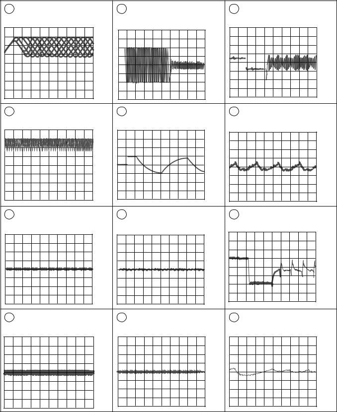
Waveforms ( |
H |
, |
J |
) |
1 50T-JUMP: After switching to the pause mode, press |
|
|
|
|
|
|
||
|
|
|
|
|
the manual search key. |
|
Note: The encircled numbers denote measuring point in the schematic diagram. |
||||||
2 FOCUS-IN: Press the play key without loading a disc. |
||||||
2 |
TP1-Pin 1: PLAY MODE (RF) |
4' TP1-Pin 2: 50T - JUMP (*1) MODE |
6' IC202-Pin 4: 50T - JUMP (*1) MODE |
||
|
500mV/div 500nsec/div |
|
(TRER) |
|
(TRDR) |
|
|
|
200mV/div 1msec/div |
|
500mV/div 1msec/div |
|
– VC |
|
– VC |
|
– GND |
|
|
|
|
|
|
2 |
TP1-Pin 1: TRACK SEARCH MODE |
5 |
IC202-Pin 3: FOCUS-IN (*2) MODE |
7 |
IC203-Pin 3: PLAY MODE (SPDR) |
|
(RF) |
|
(FODR) |
|
1V/div 50msec/div |
|
500 mV/div 200 μsec/div |
|
1V/div 200msec/div |
|
|
|
– VC |
|
– GND |
|
– GND |
|
|
|
|
|
|
3 |
TP1-Pin 6: PLAY MODE (FOER) |
5 |
IC202-Pin 3: PLAY MODE (FODR) |
7 |
IC203-Pin 3: TRACK SEARCH MODE |
|
100mV/div 10msec/div |
|
1V/div 1msec/div |
|
(SPDR) |
|
|
|
|
|
2V/div 50msec/div |
|
– VC |
|
– GND |
|
– GND |
|
|
|
|
||
4 |
TP1-Pin 2: PLAY MODE (TRER) |
6 |
IC202-Pin 4: PLAY MODE (TRDR) |
8 |
IC202-Pin 9: PLAY MODE (CADR) |
|
200mV/div 1msec/div |
|
500mV/div 1msec/div |
|
0.2V/div 2sec/div |
|
– VC |
|
– GND |
|
– GND |
16 |
|
|
|
|
|
|
|
|
|
|
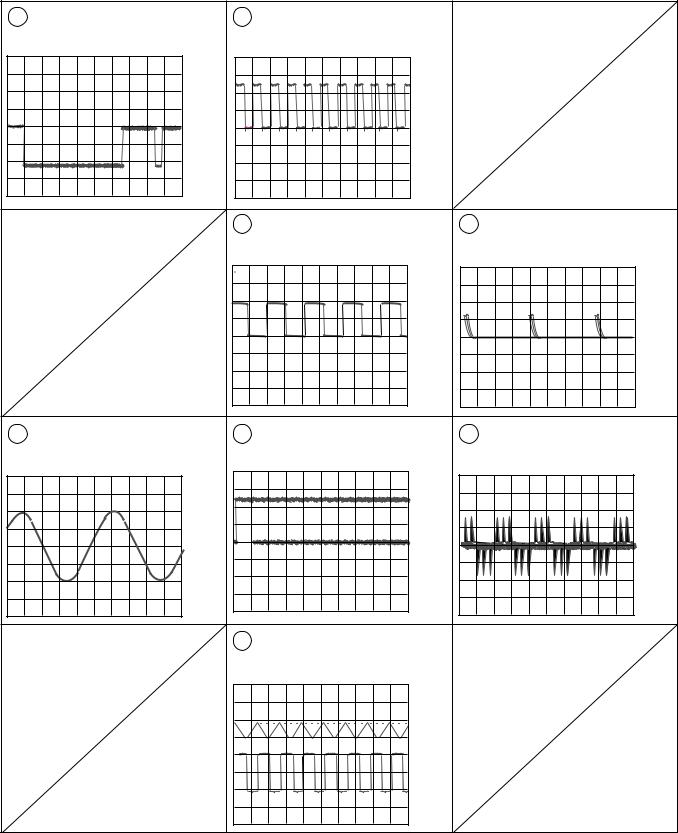
PD-F958, PD-F908 |
Waveforms |
|
|
|
|
|
8 |
IC202-Pin 9: TRACK SEARCH MODE |
16 |
IC301-Pin 54 : PLAY MODE (1kHz) |
|
|
|
(CADR) |
|
(BCK) |
|
|
|
2V/div 200msec/div |
|
2V/div 500nsec/div |
|
|
|
– GND |
|
– GND |
|
|
|
|
18 |
IC301-Pin 50 : PLAY MODE (1kHz) |
33 |
IC301-Pin 27 : PLAY MODE (MDP) |
|
|
|
(LRCK) |
|
2V/div 2 μsec/div |
|
|
|
2V/div 10 μsec/div |
|
|
|
|
|
– GND |
|
– GND |
10 |
IC301-Pin 86 : PLAY MODE (1kHz) |
19 |
IC301-Pin 52 : PLAY MODE (1kHz) |
53 IC301-Pin 38 : PLAY MODE |
|
(LOUT 1) |
|||||
|
1V/div 200msec/div |
|
(PCMD) |
|
(PCO) |
|
|
2V/div 500nsec/div |
|
2V/div 10 μsec/div |
|
|
|
|
|
||
|
|
|
– GND |
|
– GND |
|
|
|
|
|
|
|
– GND |
|
|
|
|
|
|
23 |
TRACK SEARCH MODE |
|
|
|
|
|
Upper : TP1-Pin 1 (RF) 1V/div |
|
|
|
|
|
Lower : IC151-Pin 23 (C.OUT) |
|
|
|
|
|
2V/div 50 μsec/div |
|
|
|
|
|
– GND |
|
|
|
|
|
– GND |
|
|
|
|
|
|
|
17 |
|
1 |
|
2 |
|
3 |
|
4 |
|
|
|
|
|
|
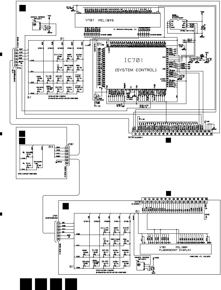
PD-F958, PD-F908
3.4 DISPLAY BOARD ASSY and SWITCH BOARD ASSY
L DISPLAY BOARD ASSY
PD-F958/KU/CA:(PWZ3904)
A
PE5032A
B
SWITCH BOARD ASSY |
|
|
|
|
M PD-F958/KU/CA: (PWZ3907) |
|
|
|
|
O PD-F908/KU,KC: (PWZ3885) |
|
|
H CN351 |
|
SWITCHES |
DISPLAY BOARD ASSY |
|
||
SWITCH BOARD ASSY |
|
|||
S751 : SL ACCESS |
S703 : MODE |
S715 |
: DISC – |
|
S752 : SL PLAY |
S704 : UNLOAD |
S716 |
: DISC + |
|
S753 : POWER STANDBY/ON |
S707 : 6 |
S717 |
: CLEAR |
|
|
S708 |
: OPEN/CLOSE |
S718 |
: PGM |
|
S709 |
: HI-LITE |
S719 |
: TITLE INPUT (PD-F958) |
|
S710 |
: 7 |
|
: RANDOM (PD-F908) |
C |
S711 : 4 1 |
S720 |
: TITLE DISPLAY (PD-F958) |
|
|
S712 |
: Á ¢ |
|
: REPEAT (PD-F908) |
|
S713 |
: BEST |
|
|
|
S714 |
: PREVIOUS |
|
|
J CN351
DISPLAY BOARD ASSY
N PD-F908/KU,KC:(PWZ3882)
D
18 L M N O
|
1 |
|
2 |
|
3 |
|
4 |
|
|
|
|
|
|
||||
|
|
|
|
|
|
1 |
|
2 |
|
3 |
|
4 |
|
|
|
|
|
|
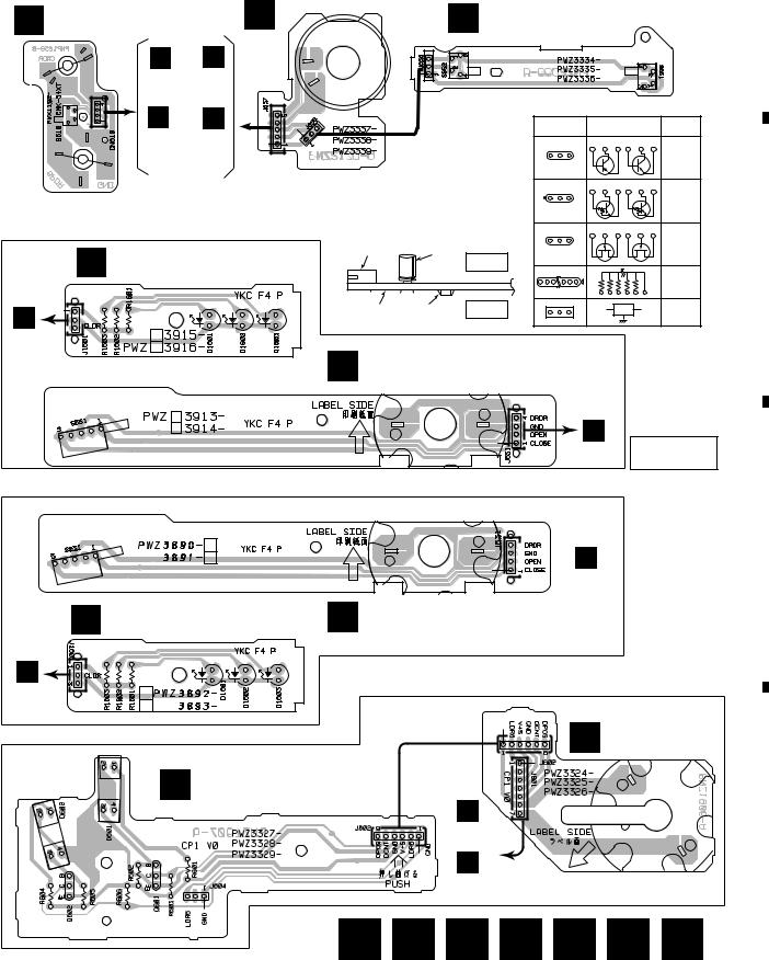
PD-F958, PD-F908
4. PCB CONNECTION DIAGRAM
4.1MECHANISM BOARD ASSY, SENSOR BOARD ASSY, LOAD SW BOARD ASSY, SELECT MOTOR BOARD ASSY, LOADING MOTOR BOARD ASSY,
CENTER LED BOARD ASSY and DOOR BOARD ASSY |
|
A |
||||||
|
|
|
|
LOADING MOTOR BOARD ASSY |
|
|
|
|
A MECHANISM BOARD ASSY |
C |
B LOAD SW BOARD ASSY |
|
|||||
CARRIAGE MOTOR |
M |
|
H |
H |
|
|
|
|
|
|
|
|
|
|
|
||
|
|
|
CN207 CN203 |
|
|
|
|
|
|
|
|
(PD-F958) |
|
PNP1458-A |
|
||
|
|
|
J |
J |
|
|
||
|
INSIDE |
|
|
Symbol in PCB |
Symbol in Schematic |
Part Name |
||
|
|
CN207 CN203 |
|
Diagrams |
B C E B C E |
|
||
|
|
|
|
|
|
Diagrams |
|
|
|
SPINDLE MOTOR |
M |
(PD-F908) |
|
B C E |
|
Transistor |
|
|
|
|
|
|
||||
|
|
|
|
|
|
|||
|
|
|
|
|
|
|
|
|
|
|
|
|
|
|
|
B C E B C E |
|
PNP1239-B |
NOTE FOR PCB DIAGRAMS: |
|
|
|
|
Transistor |
1. Part numbers in PCB diagrams match those in the |
3. The parts mounted on this PCB include all necessary |
|
||||
B C E |
with resistor |
|||||
|
schematic diagrams. |
parts for several destination. |
|
|
||
|
|
|
|
|||
For PD-F958 |
2. A comparison between the main parts of PCB and |
For further information for respective destinations, |
|
|
||
be sure to check with the schematic diagram. |
|
D G S D G S |
||||
schematic diagrams is shown below. |
|
|||||
|
|
4. Viewpoint of PCB diagrams |
|
|
Field effect |
|
F |
|
Connector |
Capacitor |
|
D G S |
transistor |
|
|
B |
||||
CENTER LED BOARD ASSY |
|
|
SIDE A |
|
||
|
|
|
|
Resistor |
||
|
|
|
|
|
|
|
|
|
|
|
|
|
array |
H |
|
P. C. Board |
Chip Part |
SIDE B |
|
3-terminal |
|
|
|
|
|
regulator |
|
|
|
|
|
|
|
|
CN208
PNP1455-B
G DOOR BOARD ASSY
H |
SIDE A |
CN205 |
For PD-F908
C


 J
J
CN205
F CENTER LED BOARD ASSY G DOOR BOARD ASSY
PNP1454-A
J |
SELECT MECHA BOARD ASSY |
|
CN208 |
||
|
||
|
SELECT MOTOR |
|
|
E BOARD ASSY |
D SENSOR BOARD ASSY
H |
D |
CN204 |
|
(PD-F958) |
|
J |
|
CN204 |
PNP1457–A |
(PD-F908) |
A B C D E F G 19
|
1 |
|
2 |
|
3 |
|
4 |
|
|
|
|
|
|
||||
|
|
|
|
|
 Loading...