


 Loading...
ORDER NO.
CRT4052
DEH-4000UB/XS/EW5
CD RDS RECEIVER
DEH-4000UB/XS/EW5
CD RECEIVER
DEH-3050UB/XS/ES
DEH-3050UB/XU/CN5
This service manual should be used together with the following manual(s):
Model No. |
Order No. |
Mech.Module |
Remarks |
||||||
|
|
|
|
|
|
|
|
|
|
CX-3240 |
CRT4050 |
S10.5COMP2-iPod/USB |
CD Mech. Module : Circuit Descriptions, Mech. Descriptions, Disassembly |
||||||
|
|
|
|
|
|
|
|
|
|
|
|
|
|
|
|
|
|
|
|
|
|
|
|
|
|
|
|
|
|
|
|
|
|
|
|
|
|
|
|
|
|
|
|
|
|
|
|
|
|
|
|
|
|
|
|
|
|
|
|
|
|
|
|
|
|
|
|
|
|
|
|
|
|
|
|
|
|
|
|
For details, refer to "Important Check Points for Good Servicing".
PIONEER CORPORATION 4-1, Meguro 1-chome, Meguro-ku, Tokyo 153-8654, Japan PIONEER ELECTRONICS (USA) INC. P.O. Box 1760, Long Beach, CA 90801-1760, U.S.A. PIONEER EUROPE NV Haven 1087, Keetberglaan 1, 9120 Melsele, Belgium
PIONEER ELECTRONICS ASIACENTRE PTE. LTD. 253 Alexandra Road, #04-01, Singapore 159936
 PIONEER CORPORATION 2007
K-ZZA. NOV. 2007 Printed in Japan
|
1 |
|
2 |
|
3 |
|
4 |
|
SAFETY INFORMATION
This service manual is intended for qualified service technicians; it is not meant for the casual do-it-yourselfer. Qualified technicians have the necessary test equipment and tools, and have been trained to properly and safely
Arepair complex products such as those covered by this manual.
Improperly performed repairs can adversely affect the safety and reliability of the product and may void the warranty. If you are not qualified to perform the repair of this product properly and safely, you should not risk trying to do so and refer the repair to a qualified service technician.
-Safety Precautions for those who Service this Unit.
When checking or adjusting the emitting power of the laser diode exercise caution in order to get safe, reliable
results.
B
Caution:
1.During repair or tests, minimum distance of 13 cm from the focus lens must be kept.
2.During repair or tests, do not view laser beam for 10 seconds or longer.
CAUTION:
USE OF CONTROLS OR ADJUSTMENTS OR PERFORMANCE OF PROCEDURES OTHERTHANTHOSE SPECIFIED HEREIN MAY RESULT IN HAZARDOUS RADIATION EXPOSURE.
C
D
CLASS 1
LASER PRODUCT
WARNING!
The AEL (accessible emission level )of the laser power output is less than CLASS 1 but the laser component is capable of emitting radiation exceeding the limit for CLASS 1.
A specially instructed person should do servicing operation of the apparatus.
E
Laser diode characteristics
Wave length : 785 nm to 814 nm
Maximum output : 1 190 W(Emitting period : unlimited)
Additional Laser Caution
Transistors Q101 in PCB drive the laser diodes.
FWhen Q101 is shorted between their terminals, the laser diodes will radiate beam. If the top cover is removed with no disc loaded while such short-circuit is continued, the naked eyes may be exposed to the laser beam.
2 |
DEH-4000UB/XS/EW5 |
|
1 |
|
2 |
|
3 |
|
4 |
|

|
5 |
|
6 |
|
7 |
|
8 |
|
CAUTION
Danger of explosion if battery is incorrectly replaced.
Replaced only with the same or equivalent type recommended by the manufacture. Discord used batteries according to the manufacture's instructions.
A
B
C
D
E
F
|
|
|
|
DEH-4000UB/XS/EW5 |
|
|
3 |
|
||
|
|
|
|
|
|
7 |
|
|
||
|
5 |
|
6 |
|
|
|
8 |
|
||
|
|
|
|
|
||||||
1  2
2  3
3  4
4
[Important Check Points for Good Servicing]
In this manual, procedures that must be performed during repairs are marked with the below symbol. Please be sure to confirm and follow these procedures.
A |
1. Product safety |
|
Please conform to product regulations (such as safety and radiation regulations), and maintain a safe servicing environment by following the safety instructions described in this manual.
1 Use specified parts for repair.
Use genuine parts. Be sure to use important parts for safety.
2 Do not perform modifications without proper instructions.
Please follow the specified safety methods when modification(addition/change of parts) is required due to interferences such as radio/TV interference and foreign noise.
B3 Make sure the soldering of repaired locations is properly performed.
When you solder while repairing, please be sure that there are no cold solder and other debris. Soldering should be finished with the proper quantity.(Refer to the example)
4 Make sure the screws are tightly fastened.
Please be sure that all screws are fastened, and that there are no loose screws.
5 Make sure each connectors are correctly inserted.
Please be sure that all connectors are inserted, and that there are no imperfect insertion.
6 Make sure the wiring cables are set to their original state.
Please replace the wiring and cables to the original state after repairs.
CIn addition, be sure that there are no pinched wires, etc.
7 Make sure screws and soldering scraps do not remain inside the product. Please check that neither solder debris nor screws remain inside the product.
8 There should be no semi-broken wires, scratches, melting, etc.on the coating of the power cord.
Damaged power cords may lead to fire accidents, so please be sure that there are no damages.
If you find a damaged power cord, please exchange it with a suitable one.
9 There should be no spark traces or similar marks on the power plug.
When spark traces or similar marks are found on the power supply plug, please check the connection and advise on secure connections and suitable usage. Please exchange the power cord if necessary.
Da Safe environment should be secured during servicing.
When you perform repairs, please pay attention to static electricity, furniture, household articles, etc. in order to prevent injuries. Please pay attention to your surroundings and repair safely.
2. Adjustments
 To keep the original performance of the products, optimum adjustments and confirmation of characteristics within specification. Adjustments should be performed in accordance with the procedures/instructions described in this manual.
3. Lubricants, Glues, and Replacement parts
Use grease and adhesives that are equal to the specified substance.
Make sure the proper amount is applied.
E
4. Cleaning
 For parts that require cleaning, such as optical pickups, tape deck heads, lenses and mirrors used in projection monitors, proper cleaning should be performed to restore their performances.
5. Shipping mode and Shipping screws
To protect products from damages or failures during transit, the shipping mode should be set or the shipping screws should be installed before shipment. Please be sure to follow this method especially if it is specified in this manual.
F
4 |
DEH-4000UB/XS/EW5 |
|
1 |
|
2 |
|
3 |
|
4 |
|

|
5 |
|
|
6 |
|
|
7 |
|
8 |
|
CONTENTS |
|
|
|
|
|
|
||
|
SAFETY INFORMATION ..................................................................................................................................... |
|
|
|
|
2 |
|||
|
1. SERVICE PRECAUTIONS................................................................................................................................ |
|
|
|
|
6 |
|||
|
1.1 SERVICE PRECAUTIONS ......................................................................................................................... |
|
|
|
|
6 |
|||
|
1.2 NOTES ON SOLDERING........................................................................................................................... |
|
|
|
|
6 |
|||
|
2. SPECIFICATIONS............................................................................................................................................. |
|
|
|
|
7 |
|||
|
2.1 SPECIFICATIONS ...................................................................................................................................... |
|
|
|
|
7 |
|||
|
2.2 DISC/CONTENT FORMAT......................................................................................................................... |
|
|
|
|
9 |
|||
|
2.3 PANEL FACILITIES .................................................................................................................................. |
|
|
|
|
10 |
|||
|
2.4 CONNECTION DIAGRAM........................................................................................................................ |
|
|
|
|
13 |
|||
|
3. BASIC ITEMS FOR SERVICE ........................................................................................................................ |
|
|
|
|
15 |
|||
|
3.1 CHECK POINTS AFTER SERVICING ..................................................................................................... |
|
|
|
|
15 |
|||
|
3.2 PCB LOCATIONS..................................................................................................................................... |
|
|
|
|
15 |
|||
|
3.3 JIGS LIST ................................................................................................................................................. |
|
|
|
|
16 |
|||
|
3.4 CLEANING ............................................................................................................................................... |
|
|
|
|
16 |
|||
|
4. BLOCK DIAGRAM .......................................................................................................................................... |
|
|
|
|
18 |
|||
|
4.1 BLOCK DIAGRAM.................................................................................................................................... |
|
|
|
|
18 |
|||
|
5. DIAGNOSIS .................................................................................................................................................... |
|
|
|
|
23 |
|||
|
5.1 OPERATIONAL FLOWCHART................................................................................................................. |
|
|
|
|
23 |
|||
|
5.2 ERROR CODE LIST................................................................................................................................. |
|
|
|
|
24 |
|||
|
5.3 CONNECTOR FUNCTION DESCRIPTION ............................................................................................. |
|
26 |
||||||
|
6. SERVICE MODE............................................................................................................................................. |
|
|
|
|
27 |
|||
|
6.1 CD TEST MODE....................................................................................................................................... |
|
|
|
|
27 |
|||
|
7. DISASSEMBLY ............................................................................................................................................... |
|
|
|
|
30 |
|||
|
8. EACH SETTING AND ADJUSTMENT............................................................................................................ |
|
|
|
|
35 |
|||
|
8.1 PCL OUTPUT CONFIRMATION .............................................................................................................. |
|
|
|
|
35 |
|||
|
8.2 CHECKING THE GRATING AFTER CHANGING THE PICKUP UNIT |
.................................................... |
36 |
||||||
|
9. EXPLODED VIEWS AND PARTS LIST .......................................................................................................... |
|
|
|
|
38 |
|||
|
9.1 PACKING.................................................................................................................................................. |
|
|
|
|
38 |
|||
|
9.2 EXTERIOR(1) ........................................................................................................................................... |
|
|
|
|
40 |
|||
|
9.3 EXTERIOR(2) ........................................................................................................................................... |
|
|
|
|
42 |
|||
|
9.4 CD MECHANISM MODULE ..................................................................................................................... |
|
|
|
|
44 |
|||
|
10. SCHEMATIC DIAGRAM................................................................................................................................ |
|
|
|
|
46 |
|||
|
10.1 OVERALL CONNECTION DIAGRAM(GUIDE PAGE)............................................................................ |
|
46 |
||||||
|
10.2 KEYBOARD UNIT .................................................................................................................................. |
|
|
|
|
52 |
|||
|
10.3 CD MECHANISM MODULE(GUIDE PAGE)........................................................................................... |
|
54 |
||||||
|
10.4 WAVEFORMS......................................................................................................................................... |
|
|
|
|
60 |
|||
|
11. PCB CONNECTION DIAGRAM .................................................................................................................... |
|
|
|
|
64 |
|||
|
11.1 TUNER AMP UNIT ................................................................................................................................. |
|
|
|
|
64 |
|||
|
11.2 KEYBOARD UNIT................................................................................................................................... |
|
|
|
|
68 |
|||
|
11.3 CD CORE UNIT(S10.5COMP2-USB)..................................................................................................... |
|
|
|
|
70 |
|||
|
12. ELECTRICAL PARTS LIST........................................................................................................................... |
|
|
|
|
72 |
|||
|
|
|
|
DEH-4000UB/XS/EW5 |
|
|
5 |
||
|
|
|
|
|
|
7 |
|
||
|
5 |
|
6 |
|
|
|
8 |
||
|
|
|
|
||||||
A
B
C
D
E
F
|
1 |
|
2 |
|
3 |
|
4 |
|
1. SERVICE PRECAUTIONS
1.1 SERVICE PRECAUTIONS
A
- Service Precaution
1. You should conform to the regulations governing the product (safety, radio and noise, and other regulations), and should keep the safety during servicing by following the safety instructions described in this manual.
2.Before disassembling the unit, be sure to turn off the power. Unplugging and plugging the connectors during power-on mode may damage the ICs inside the unit.
3.To protect the pickup unit from electrostatic discharge
Bduring servicing, take an appropriate treatment (shorting-solder) by referring to "the DISASSEMBLY".
4.After replacing the pickup unit, be sure to check the grating.
5.Be careful in handling ICs. Some ICs such as MOS type are so fragile that they can be damaged by electrostatic induction.
6.The sheet (Mechanism cover) can not be reused if you removed it.
C
|
|
|
|
|
|
|
|
|
|
|
|
|
|
|
|
|
|
|
|
|
|
|
|
|
|
|
|
|
1.2 NOTES ON SOLDERING |
||||||
|
|
For environmental protection, lead-free solder is used on the printed circuit boards mounted in this unit. |
||||||
|
|
|||||||
|
|
|||||||
|
|
Be sure to use lead-free solder and a soldering iron that can meet specifications for use with lead-free solders for repairs |
||||||
|
|
accompanied by reworking of soldering. |
||||||
D |
Compared with conventional eutectic solders, lead-free solders have higher melting points, by approximately 40 C. |
|||||||
|
|
Therefore, for lead-free soldering, the tip temperature of a soldering iron must be set to around 373 C in general, although |
||||||
|
|
the temperature depends on the heat capacity of the PC board on which reworking is required and the weight of the tip of |
||||||
|
|
the soldering iron. |
||||||
|
|
Compared with eutectic solders, lead-free solders have higher bond strengths but slower wetting times and higher melting |
||||||
|
|
temperatures (hard to melt/easy to harden). |
||||||
|
|
|||||||
|
|
The following lead-free solders are available as service parts: |
||||||
|
|
Parts numbers of lead-free solder: |
||||||
|
|
GYP1006 1.0 in dia. |
||||||
|
|
GYP1007 0.6 in dia. |
||||||
E |
GYP1008 0.3 in dia. |
|||||||
|
|
|
|
|
|
|
|
|
|
|
|
|
|
|
|
|
|
F
6 |
DEH-4000UB/XS/EW5 |
|
1 |
|
2 |
|
3 |
|
4 |
|

|
5 |
|
6 |
|
7 |
|
8 |
|
2. SPECIFICATIONS
2.1SPECIFICATIONS
-EW5 Model
A
Backup current
.................................... 5 mA or less
B
C
D
E
F
|
|
|
|
DEH-4000UB/XS/EW5 |
|
|
7 |
|
||
|
|
|
|
|
|
7 |
|
|
||
|
5 |
|
6 |
|
|
|
8 |
|
||
|
|
|
|
|
||||||

|
1 |
|
2 |
|
3 |
|
4 |
|
- ES Model
A
Backup current
.................................... 5 mA or less
B
C
D
E
F
8 |
DEH-4000UB/XS/EW5 |
|
1 |
|
2 |
|
3 |
|
4 |
|

|
5 |
|
6 |
|
7 |
|
8 |
|
- CN5 Model
A
Backup current
.................................... 5 mA or less
B
C
D
E
2.2 DISC/CONTENT FORMAT
F
|
|
|
|
|
|
|
|
|
|
|
|
|
|
|
|
|
|
|
|
|
|
|
|
|
|
|
|
|
|
|
|
|
|
|
|
|
|
|
|
|
|
|
|
|
|
|
|
|
|
|
|
|
|
|
|
|
|
|
|
|
|
|
|
|
|
|
|
|
|
|
|
|
|
|
|
|
|
DEH-4000UB/XS/EW5 |
|
|
9 |
|
||
|
5 |
|
|
|
6 |
|
|
7 |
|
8 |
|
|||||
|
|
|
|
|
||||||||||||

|
1 |
|
2 |
|
3 |
|
4 |
|
2.3 PANEL FACILITIES
A
B
C
D
E
F
10 |
DEH-4000UB/XS/EW5 |
|
1 |
|
2 |
|
3 |
|
4 |
|
|
5 |
|
6 |
|
7 |
|
8 |
|
A
B
C
D
E
F
|
|
|
|
DEH-4000UB/XS/EW5 |
|
|
11 |
|
||
|
|
|
|
|
|
7 |
|
|
||
|
5 |
|
6 |
|
|
|
8 |
|
||
|
|
|
|
|
||||||

|
1 |
|
2 |
|
3 |
|
4 |
|
A
B
C
D
E
F
12 |
DEH-4000UB/XS/EW5 |
|
1 |
|
2 |
|
3 |
|
4 |
|

|
5 |
|
6 |
|
7 |
|
8 |
|
2.4CONNECTION DIAGRAM
-EW5 Model
A
B
C
D
E
F
|
|
|
|
DEH-4000UB/XS/EW5 |
|
|
13 |
|
||
|
|
|
|
|
|
7 |
|
|
||
|
5 |
|
6 |
|
|
|
8 |
|
||
|
|
|
|
|
||||||

|
1 |
|
2 |
|
3 |
|
4 |
|
- ES, CN5 Model
A
B
C
D
E
F
14 |
DEH-4000UB/XS/EW5 |
|
1 |
|
2 |
|
3 |
|
4 |
|
|
5 |
|
6 |
|
7 |
|
8 |
3. BASIC ITEMS FOR SERVICE
3.1 CHECK POINTS AFTER SERVICING
To keep the product quality after servicing, please confirm following check points.
No. |
|
Procedures |
Item to be confirmed |
1 |
|
Confirm whether the customer complain has been |
The customer complain must not be reappeared. |
|
|
solved. |
Display, audio and operations must be normal. |
|
|
If the customer complain occurs with the specific |
|
|
|
media, use it for the operation check. |
|
|
|
|
|
2 |
CD |
Play back a CD. |
No malfunction on display, audio and operation. |
|
|
(Track search) |
Display, audio and operations must be normal. |
3 |
FM/AM tuner |
Check FM/AM tuner action. |
Display, audio and operations must be normal. |
|
|
(Seek, Preset) |
|
|
|
Switch band to check both FM and AM. |
|
|
|
|
|
4 |
|
Check whether no disc is inside the product. |
The media used for the operating check must be |
|
|
|
ejected. |
5 |
|
Appearance check |
No scratches or dirt on its appearance after |
|
|
|
receiving it for service. |
See the table below for the items to be checked regarding audio:
Item to be checked regarding audio
Distortion
Noise
Volume too low
Volume too high
Volume fluctuating
Sound interrupted
A
B
C
3.2 PCB LOCATIONS
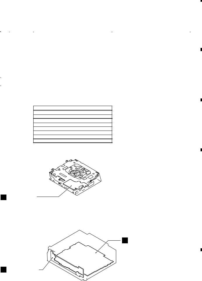
C CD Core Unit
(S10.5COMP2-USB)
|
|
D |
|
Unit Number |
: YWM5203(EW5) |
|
|
Unit Number |
: YWM5205(ES) |
|
|
Unit Number |
: YWM5207(CN5) |
|
|
Unit Name |
: Tuner Amp Unit |
|
|
Unit Number |
: (EW5) |
|
|
|
|||
Unit Number |
: (ES) |
|
|
Unit Name |
: Keyboard Unit |
|
|
Unit Number |
: (CN5) |
|
|
Unit Name |
: Keyboard Unit |
|
|
Unit Number |
: CWX3527 |
E |
|
Unit Name |
: CD Core Unit |
||
|
|||
|
(S10.5COMP2-USB) |
|
A Tuner Amp Unit
B Keyboard Unit
F
|
|
|
|
DEH-4000UB/XS/EW5 |
|
|
15 |
|
||
|
|
|
|
|
|
7 |
|
|
||
|
5 |
|
6 |
|
|
|
8 |
|
||
|
|
|
|
|
||||||
|
|
1 |
|
2 |
|
|
3 |
|
4 |
|
|
|||||||
|
|
3.3 JIGS LIST |
|
|
|
|
|
|
|
|
|
|
|
|
||||
|
|
- Jigs List |
|
|
|
|
|
|
|
|
|
|
|
|
||||
|
|
|
|
|
|
|
|
|
|
|
|
|
|
|
|
|
||
|
|
|
|
|
|
|
|
|
|
|
|
|
|
|
|
|
||
|
|
|
|
|
Name |
|
|
Jig No. |
|
|
|
|||||||
A |
|
|
|
|
|
Remarks |
|
|
|
|||||||||
Test Disc |
|
TCD-782 |
Checking the grating |
|
|
|
||||||||||||
|
|
|
|
|
|
|
|
|||||||||||
|
|
|
|
L.P.F. |
|
|
|
|
Checking the grating (Two pieces) |
|
|
|
||||||
|
- Grease List |
|
|
|
|
|||
|
|
|
|
|
||||
|
|
|
|
|
|
|
|
|
|
|
|
|
|
|
|
|
|
|
|
|
Name |
|
Grease No. |
|||
|
|
|
|
|
Remarks |
|||
|
|
|
|
|
|
|
|
|
B |
|
Grease |
GEM1024 |
CD Mechanism Module |
||||
|
Grease |
GEM1045 |
CD Mechanism Module |
|||||
|
|
|||||||
|
3.4 CLEANING |
|
|
|
- Jigs List |
|
|
|
Name |
Jig No. |
Remarks |
|
Test Disc |
TCD-782 |
Checking the grating |
C |
Before shipping out the product, be sure to clean the |
Checking the grating (Two pieces) |
|
|
L.P.F. |
|
|
|
following portions by using the prescribed cleaning |
|
|
|
tools: |
|
|
|
Portions to be cleaned |
Cleaning tools |
|
|
CD pickup lenses |
Cleaning liquid : GEM1004 |
|
|
|
Cleaning paper : GED-008 |
|
|
- Grease List |
|
|
|
Name |
Grease No. |
Remarks |
|
Grease |
GEM1024 |
CD Mechanism Module |
|
Grease |
GEM1045 |
CD Mechanism Module |
D |
|
|
|
Before shipping out the product, be sure to clean the following portions by using the prescribed cleaning tools:
E |
Portions to be cleaned |
Cleaning tools |
|
CD pickup lenses |
Cleaning liquid : GEM1004 |
|
|
Cleaning paper : GED-008 |
|
|
|
|
|
|
F
16 |
DEH-4000UB/XS/EW5 |
|
1 |
|
2 |
|
3 |
|
4 |
|

|
5 |
|
6 |
|
7 |
|
8 |
|
A
B
C
D
E
F
|
|
|
|
DEH-4000UB/XS/EW5 |
|
|
17 |
|
||
|
|
|
|
|
|
7 |
|
|
||
|
5 |
|
6 |
|
|
|
8 |
|
||
|
|
|
|
|
||||||
A
B
C
D
E
F
1 |
|
2 |
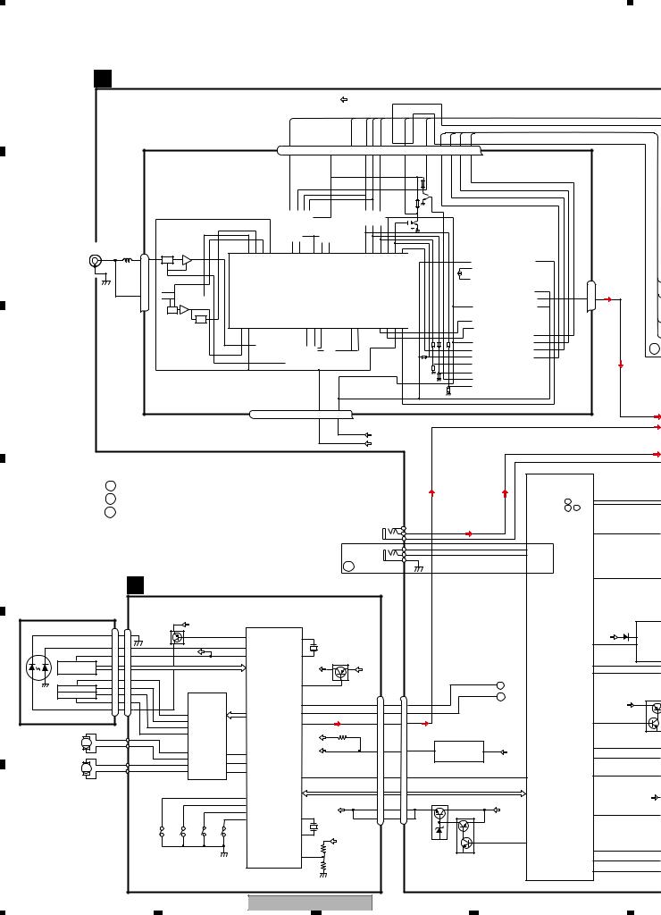
4. BLOCK DIAGRAM
4.1 BLOCK DIAGRAM
A TUNER AMP UNIT
FM/AM TUNER UNIT
ANTENNA CN401 |
|
AM ANT |
FMRF |
1 |
|
|
|
1 |
ATT |
|
|
|
|
2,3
FM ANT
3  ATT
ATT FMRF
FMRF
RF adj
ANT adj
|
3 |
|
4 |
|
|
|
|
|
|
|
|
|
|
|
|
|
VDD |
TUNPDI TUNPCK |
CE1 |
|
|
LDET |
|
TUNPDO |
|
|
|
|
|
|
|
|
|
||||||||||
|
|
|
|
CE2 |
|
|
|
|
|
|
|
SL |
|
|
|
|
|
|
|
|
|
|
|
|
|||||||||||||||
|
|
|
|
|
|
|
|
|
|
|
|
|
|
|
|
|
|
|
|
|
|
|
|
|
|
|
|
|
|
|
|
|
|
|
|
|
|
|
|
|
|
|
7 |
6 |
|
|
|
13 |
|
5 |
10 |
9 |
8 |
|
11 |
|
|
|
|
|
14 |
18 |
19 |
20 |
21 |
|
|||||||||||||
|
|
|
NC |
|
CE2 |
|
|
|
|
ROM VDD |
|
SL |
DI |
CK |
CE1 |
|
LDET |
|
|
|
|
|
DO |
|
|
|
RDS CK |
|
RDS DATA |
RDS LOCK |
RDS HSLK |
||||||||
|
|
|
|
|
|
|
|
|
|
|
|
|
|
|
|
|
|
|
|
|
|
|
|
|
|
|
|
|
|
|
|
|
|
|
|
|
|
|
|
|
|
|
|
|
|
|
|
|
|
|
|
|
|
|
|
|
|
|
|
|
|
|
|
|
|
|
|
|
|
|
|
|
|
|
|
|
|
|
|
|
|
|
|
|
|
|
|
|
|
|
|
|
|
|
|
|
|
|
|
|
|
|
|
|
|
|
|
|
|
|
|
|
|
|
|
|
|
|
|
|
|
|
|
|
|
|
|
|
|
|
|
|
|
|
|
|
|
|
|
|
|
|
|
|
|
|
|
|
|
|
|
|
|
|
|
|
|
||
|
|
|
|
|
|
|
|
|
|
|
|
|
|
|
|
|
|
|
|
|
|
|
|
|
|
|
|
|
|
|
|
|
|
|
|
||||
|
|
|
IC3 EEPROM |
|
|
|
|
|
|
|
|
IC5 |
|
|
|
|
|
|
|
|
|
|
|
|
|
|
|
|
|
|
|
|
|
|
|
||||
|
|
|
|
|
5.0V |
|
|
|
|
|
|
|
|
|
5V →3.3V |
|
|
|
|
|
|
|
|
|
|
|
|
|
|
|
|
|
|
|
|
|
|
||
|
|
|
|
|
|
|
|
|
|
|
|
|
|
|
|
|
|
|
|
|
|
|
|
|
|
|
|
|
|
|
|
|
|
|
|
|
|
||
|
|
|
|
|
OSC |
|
|
|
LPF |
|
|
|
|
|
|
|
|
|
|
|
|
|
|
|
|
|
|
|
|
|
|
|
|
|
|
|
|
|
|
|
|
|
|
|
|
|
|
|
|
|
|
|
|
|
|
|
|
|
|
|
|
|
|
|
|
|
|
|
|
|
|
|
|
|
|
|
|
IC2 |
|
|
|
|
|
|
|
|
|
|
|
|
|
|
|
|
|
|
|
|
|
|
|
|
|
|
|
|
|
|
|
|
|
|
|
|
|
|
|
|
|
|
|
|
|
|
|
IC1 |
|
|
|
|
|
|
|
|
|
|
|
|
|
|
|
|
|
|
|
|
|
|
|
|
|
|
|
|
|
|
|
2.5V |
|
|
|
|
|
|
|
|
|
|
|
|
|
|
|
|
|
|
|
|
|
|
|
|
|
|
|
|
|
|
|
|
|
|
|
|
|
|
|
|
|
|
|
|
|
|
|
3.3V |
|
|
|
|
|
|
|
|
|
|
|
|
|
|
|
|
|
|
|
|
|
|
|
|
|
|
|
|
|
|
|
|
Lch 23 |
|
|
|
|
|
MIXER, IF AMP |
|
|
|
|
|
|
|
|
|
|
|
|
|
|
|
|
|
|
|
|
|
|
|
|
|
|
||||||||
|
|
|
|
|
|
|
|
|
|
|
|
|
|
|
|
|
|
|
|
|
|
|
|
|
|
|
|
|
|
DET, FM MPX, |
|
||||||||
|
|
|
|
|
|
|
|
|
|
|
|
|
|
|
|
|
|
|
|
|
|
|
|
|
|
|
|
|
|
|
|
|
|
|
|
|
|
|
|
|
|
|
|
|
|
|
|
|
|
|
|
|
|
|
|
|
|
|
|
|
|
|
|
|
|
|
|
|
|
|
|
|
|
|
|
|
|
RDS DECODER |
|
|
|
|
|
|
|
|
|
|
|
|
|
|
|
|
|
|
|
|
|
|
|
|
|
|
|
|
|
|
|
|
|
|
|
|
|
|
|
|
|
|
|
|
|
|
|
|
|
|
|
|
|
|
|
|
|
|
|
|
|
|
|
|
|
|
|
|
|
|
|
|
|
|
|
|
|
|
|
|
|
|
|
|
|
|
|
|
|
|
|
|
|
|
|
|
|
|
|
|
|
|
|
|
|
|
|
|
|
|
|
|
|
|
|
|
|
|
|
|
|
|
|
OSCGND |
|
|
AUDIOGND |
T51 |
|
|
|
CF52 |
|
|
|
|
|
|
|
|
|
|
|
|
|
|
|
|
|
|
|
|
|
|
|
|
|
|
|
|
|
RFGND |
DGND |
|
NC |
VCC |
|
|
3.3VDD |
|
|
|
|
|
|
|
|
|
|
|
|
|
|
|
|
|
|
|
|
|
|
|
|
|
|
|
|||||
|
|
|
|
|
|
|
|
|
|
|
|
|
|
|
|
|
|
|
|
|
|
|
|
|
|
|
|
|
|
||||||||||
|
|
|
|
|
|
|
|
|
|
|
|
|
|
|
|
|
|
|
|
|
|
|
|
|
|
|
|
|
|
||||||||||
|
|
|
|
|
|
|
|
|
|
|
|
|
|
|
|
|
|
|
|
|
|
|
|
|
|
|
|
|
|
||||||||||
|
|
|
|
|
|
|
|
|
|
|
|
|
|
|
|
|
|
|
|
|
|
|
|
|
|
|
|
|
|
||||||||||
|
|
|
|
|
|
|
|
|
|
|
|
|
|
|
|
|
|
|
|
|
|
|
|
|
|
|
|
|
|
||||||||||
|
|
|
|
|
IC4 |
|
|
|
|
|
|
|
|
|
|
|
|
|
|
|
|
|
|
|
|
|
|
|
|||||||||||
2 |
12 |
15 |
22 |
16 |
4 |
17 |
3.3V |
3.3V →2.5V |
2.5V |
|
|
|
|
|
|
|
|
|
|
|
|
|
|
|
|||||||||||||||
|
|
|
|
|
|
|
|
|
|
|
|
|
|
|
|
|
|
|
|
|
|
|
|
|
|
|
|||||||||||||
|
|
|
|
|
|
|
|
|
|
|
|
|
|
|
|
|
|
|
|
|
|
|
|
|
|
|
|||||||||||||
A
VD
TUNL
CDL
|
|
|
|
|
|
|
|
|
|
|
|
|
|
|
|
VDD3.3V |
|
|
|
|
|
|
|
|
|
|
|
||
|
|
|
|
|
|
|
|
|
|
|
|
|
|
|
|
VCC |
|
|
|
|
|
|
|
|
|
|
|
|
|
|
|
|
|
|
|
|
|
|
|
|
|
|
|
|
|
|
|
|
|
|
|
|
|
|
|
|
|
AUXL |
|
|
|
|
|
|
|
|
|
|
|
|
|
|
|
|
|
|
|
|
|
|
|
|
|
|
|
|
|
AUXGND |
|
|
|
|
A : DEH-4000UB/XS/EW5 |
|
|
|
|
|
|
|
|
|
|
|
|
|
|
|
SYSTEM |
|
|
|
|
||||||
|
|
|
|
|
|
|
|
|
|
|
|
|
|
|
|
|
|
CONTROLLER |
|
|
|
||||||||
|
|
|
B : DEH-3050UB/XS/ES |
|
|
|
|
|
|
|
|
|
|
|
|
|
|
|
IC 601(2/2) |
|
|
|
|||||||
|
|
|
|
|
|
|
|
|
|
|
|
|
|
|
|
|
|
PEG475A: A |
|
|
|
|
|||||||
|
|
|
C : DEH-3050UB/XU/CN5 |
|
|
|
|
|
|
|
|
|
|
|
|
|
|
|
PEG409A: B , C |
|
|
|
|||||||
|
|
|
|
|
|
|
|
|
|
|
CN621 |
|
|
|
|
|
|
|
|
|
|
|
|||||||
|
|
|
|
|
|
|
|
|
|
|
|
|
|
|
|
|
|
6 |
|
|
|
|
|
|
|
|
|
|
|
|
|
|
|
|
|
|
|
|
|
|
|
|
|
|
|
|
|
|
|
|
|
|
|
|
|
|
|
|
|
|
|
|
|
|
|
|
|
|
|
|
|
|
|
|
|
REAR |
|
|
5 AUXL |
|
|
|
|
|
|
MUTE |
40 |
|
|
|
|
|
|
|
|
|
|
|
|
|
|
|
|
|
|
AUX |
|
|
4 AUXGND |
|
|
|
|
|
|
|
|
|
|
|
|
|
|
|
|
|
|
|
|
|
|
|
|
|
|
WIRED |
|
|
3 KEY1 |
|
|
|
|
34 |
KEYD |
|
|
|
|
|
|
|
|
|
|
|
|
|
|
|
|
|
|
|
|
|
|
2 KEY2 |
|
|
|
|
94 |
KEYAD |
|
|
|
|
|
|
|
|
|
|
|
|
|
|
|
|
|
|
|
|
|
REMOTE |
|
1 |
|
|
|
|
|
|
|
|
|
||
|
|
|
|
|
|
|
|
|
|
|
|
|
|
|
|
|
|
|
|
|
|
|
|
|
|
|
|||
|
|
|
|
|
|
|
|
|
|
|
|
|
|
|
|
A |
|
|
|
|
|
|
|
|
|
|
|
|
|
|
|
|
|
|
C CD CORE UNIT(S10.5COMP2-USB) |
|
|
|
|
|
|
|
|
|
|
|
SYSPW |
48 |
|
|
|||||||||
|
|
|
|
|
|
|
|
|
|
|
|
|
|
|
|
|
|
|
|
||||||||||
PICKUP UNIT |
|
|
|
|
|
|
|
|
RF-AMP, CD DECODER, |
|
|
|
|
|
|
|
|
|
|
|
|
USB5V REGUL |
|||||||
(P10.5)(SERVICE) |
|
|
|
|
|
|
|
MP3/WMA DECODER, |
|
|
|
|
|
|
|
|
|
|
|
|
|||||||||
|
|
|
|
|
|
|
|
|
|
|
|
|
|
|
|
|
|
|
IC501 |
||||||||||
|
|
|
|
|
DIGITAL SERVO / DATA PROCESSOR CPU, |
|
|
|
|
|
|
|
|
|
|
|
|||||||||||||
|
|
|
|
|
|
|
|
|
|
|
|
|
|
|
|
|
|
|
|
BD9781HF |
|||||||||
LASER |
|
|
|
|
|
CN101 |
|
VDD2 |
|
|
USB HOST CONTROLLER |
|
|
|
|
|
|
|
|
|
|
|
|
|
|
||||
|
|
|
|
|
|
|
|
|
|
|
|
|
|
|
|
|
|
|
|
|
|
|
|
|
|
|
|
||
DIODE |
|
|
LD- 15 |
15 |
|
|
|
|
|
141 |
LD |
|
|
1 |
|
|
|
|
|
|
|
|
|
|
|
B.UP |
1 VIN |
|
|
|
|
|
|
Q101 |
|
|
|
USBXTAL |
|
|
|
|
|
|
|
|
|
|
|
S |
|||||||||
|
|
|
MD |
|
|
|
|
|
|
|
142 |
|
|
|
|
X205 |
|
|
|
|
|
|
|
|
|
SYNC |
28 |
7 |
F |
|
|
|
5 |
5 |
|
|
|
|
|
PD |
|
|
|
|
|
|
|
|
|
|
|
|
|
EN |
|||||
|
|
|
|
|
REFO |
|
|
|
|
|
|
48MHz |
|
|
|
|
|
|
|
|
|
|
|
|
IN |
||||
|
|
|
VREF |
8 |
8 |
|
|
|
133 |
REFOUT |
/USBXTAL 2 |
|
|
|
|
|
|
|
|
|
|
|
|
||||||
|
|
|
|
|
|
|
|
Q102 |
|
|
|
|
|
|
|
|
|
|
|
|
|
||||||||
|
HOLOGRAM |
|
|
|
|
|
AC,BD,E,F |
|
|
|
|
|
|
|
|
|
|
|
|
|
|
|
USBCTL |
24 |
|
|
|||
|
|
|
|
|
|
|
|
|
|
|
|
|
|
|
|
|
|
|
|
|
|
|
|
||||||
|
|
|
|
|
|
|
|
|
|
|
|
|
VCC |
VDD2 |
|
|
|
|
|
|
|
|
|
25 |
|
|
|||
|
UNIT |
|
|
|
|
|
|
|
|
|
|
|
|
|
|
|
|
|
|
|
|
|
|
FLG |
|
|
|||
|
|
|
|
|
|
FOM |
|
|
|
|
|
|
|
|
|
|
|
|
|
|
|
|
|
|
|
|
|
|
|
|
|
|
FOM |
3 |
3 |
|
CD |
|
|
|
/PUEN |
39 |
|
|
|
|
|
|
|
E |
|
|
|
|
|
|
|||
|
|
|
FOP |
|
|
FOP |
|
|
|
|
|
|
|
|
|
|
|
|
|
|
|
|
|
||||||
MONITOR |
FOCUS ACT. |
2 |
2 |
|
DRIVER |
|
|
|
|
|
|
|
|
|
|
|
|
|
|
|
|
|
|
ILM |
|||||
TRACKING ACT. |
TOP |
1 |
1 |
TOP |
|
|
|
|
|
|
|
|
|
CN701 |
|
|
CN701 |
|
|
D |
|
|
|
|
|
||||
DIODE |
|
|
TOM |
4 |
4 |
TOM |
|
IC301 |
|
|
|
|
|
5 |
DP 16 |
|
DP |
|
|
|
|
|
|
|
|
Q841 |
|||
|
|
|
|
|
|
IC201 |
DP |
4 |
|
|
|
|
|
|
|
|
B. UP |
|
|||||||||||
|
|
|
LD+ |
|
|
BA5839FP |
TD,FD |
|
|
|
|
|
|
|
|
|
|||||||||||||
|
|
|
14 |
14 |
|
|
|
|
DM 17 |
|
|
|
|
|
|
|
|
|
|
|
|
||||||||
|
|
|
|
|
|
|
12 |
FOM |
|
|
|
PE5611B |
DM |
4 |
3 |
DM |
|
|
|
|
|
|
|
|
|
|
|||
|
|
|
|
|
|
|
11 |
FOP |
|
SD,MD |
|
|
LOUT |
55 |
LOUT |
13 |
7 |
CDL |
|
|
|
|
|
|
ILMPW |
51 |
|
|
|
|
|
|
|
|
|
|
14 |
TOP |
|
|
|
|
|
|
|
|
|
|
|
|
|
|
|
|
|
||||
|
|
|
|
|
|
|
|
|
|
|
|
|
|
|
|
|
|
|
|
|
|
|
|
|
|
|
|
||
|
|
|
|
|
|
|
13 |
TOM |
|
|
|
|
|
|
VDD2 |
|
|
|
|
CD 3.3V REGULATOR |
|
|
|
|
|
|
Q842 |
||
|
SPINDLE |
M |
|
|
|
|
|
|
|
|
|
|
|
|
|
|
|
|
|
|
|
|
|
|
|||||
|
|
|
|
|
|
|
|
|
|
|
|
|
|
|
|
|
|
|
|
|
|
|
|
|
4 |
|
|
||
|
MOTOR |
|
|
|
|
|
16 |
|
|
|
|
|
|
|
|
VDD 9 |
|
CDVDD |
3 |
IC702 |
1 |
|
|
|
ROT0 |
|
|
||
|
|
|
|
|
|
|
SOP |
LOEJ |
22 |
28 |
LOEJ |
|
|
VDD |
11 |
VDD |
|
|
3 |
|
|
||||||||
|
|
|
|
|
|
|
15 |
SOM |
|
21 |
20 |
|
|
|
|
|
|
|
NJM2885DL1-33 |
|
|
|
|
ROT1 |
|
|
|||
LOAD/ CARRIAGEMOTOR |
M |
|
|
|
|
18 |
LCOP |
CLCONT |
CLCONT |
|
|
|
|
|
|
|
|
|
|
|
|
|
|
|
|
|
|||
|
|
|
|
17 |
CONT |
9 |
41 |
CONT |
|
|
|
|
|
|
|
|
|
|
|
|
|
|
82 |
|
|
||||
|
|
|
|
|
|
|
|
LCOM |
|
|
/RESET |
16 |
/RESET |
8 |
12 |
CDRST |
|
|
|
|
23 |
CDRST |
JOYST |
|
|
||||
|
|
|
|
|
|
|
|
|
|
|
|
|
|
|
|
|
|
|
|
||||||||||
|
|
|
|
|
|
|
|
|
|
|
|
|
|
|
|
BRST,BRXEN,BSRQ |
|
|
|
BRST,BRXEN,BSRQ,BDATA,BSCK |
|
|
|
|
|
|
|||
|
|
|
|
|
|
|
|
|
|
|
8 |
12EJ |
|
|
|
BDATA,BSCK |
|
|
|
Q702 |
VD 7.5V REGULATOR |
|
|
|
|
VDD |
|||
|
|
|
|
|
|
|
|
|
|
|
7 |
8EJ |
|
|
|
VD |
|
|
VD |
|
|
|
|
|
|
||||
|
|
|
|
|
|
|
|
|
|
|
|
|
|
|
|
|
|
|
|
|
|
|
|
|
|
|
|||
|
|
|
|
|
|
|
|
|
|
|
10 |
DSCSNS |
|
|
50 |
VD |
2 |
18 |
|
|
Q701 |
|
B.UP |
|
|
SWVDD |
49 |
|
|
|
|
|
|
|
|
|
|
|
|
|
9 |
HOME |
|
XTAL |
|
1 |
19 |
|
|
|
|
|
|
|
|
|
|||
|
|
|
|
|
|
|
|
|
|
|
|
|
|
|
|
|
|
|
|
|
|
|
|||||||
|
|
|
|
|
|
S904 |
S905 |
|
|
S901 |
|
|
|
|
X201 |
|
|
|
|
|
|
|
|
|
|
|
|
|
|
|
|
|
|
|
|
|
|
|
|
/XTAL |
52 |
16.93MHz |
|
|
|
|
|
|
|
|
|
|
|
|
|
||||
|
|
|
|
|
|
12EJ |
8EJ |
|
|
HOME |
|
|
|
|
|
|
|
|
|
|
22 |
|
|
|
|
|
|||
|
|
|
|
|
|
|
|
|
|
|
|
|
|
|
|
VD |
|
|
|
|
|
|
|
VDCONT |
|
|
|
|
|
|
|
|
|
|
|
|
|
|
|
|
|
|
|
|
|
|
|
|
|
|
|
|
|
|
|
|
|
||
|
|
|
|
|
|
|
|
S903 |
|
|
|
|
|
|
|
|
|
|
|
|
|
|
|
|
DPDT |
35 |
|
|
|
|
|
|
|
|
|
|
|
|
|
|
|
|
11 |
|
|
|
|
|
|
|
|
|
|
|
|
|
|||
|
|
|
|
|
|
|
|
DSCSNS |
|
|
|
VDSENS |
|
|
|
|
|
|
|
|
|
|
|
36 |
|
|
|||
|
|
|
|
|
|
|
|
|
|
|
|
|
|
|
|
|
|
|
|
|
|
|
|
KYDT |
|
|
|||
|
|
|
|
|
|
|
|
|
|
|
|
|
|
|
|
|
|
|
|
|
|
|
|
|
|
|
|
|
|
|
|
|
|
|
|
|
|
|
|
|
|
|
|
|
|
|
|
|
|
|
|
|
|
|
|
DSENS |
19 |
|
|
|
|
|
|
|
|
|
|
|
|
|
|
|
|
|
|
|
|
|
|
|
|
|
|
|
|
|
|
|
|
18 |
|
|
|
|
|
|
|
|
|
|
|
DEH-4000UB/XS/EW5 |
|
|
|
|
|
|
|
|
|
|
|
|
|
||||
1 |
|
|
|
|
|
|
|
|
|
2 |
|
|
|
|
|
|
3 |
|
|
|
|
|
|
4 |
|
|
|
|
|
|
|
|
|
|
|
|
|
|
|
|
|
|
|
|
|
|
|
|
|
|
|
|
|
|
|
||||

|
|
|
|
|
|
5 |
|
|
|
|
|
|
|
6 |
|
|
|
|
|
|
|
7 |
|
|
|
|
|
|
|
|
|
8 |
|
|
|
|
|
|
|
|
|
|
|
|
|
|
|
|
|
|
|
|
|
|
|
|
|
|
|
|
|
|
|
|
|
|
|
|
|
|
A |
|
|
|
|
|
|
|
|
|
|
|
|
|
|
|
|
|
|
|
|
|
|
|
|
|
|
|
|
MUTE |
CN351 |
|
|
|
|
||
|
|
|
|
|
|
|
|
|
|
|
|
|
|
|
|
SWL |
|
|
|
|
|
|
|
|
|
|
|
SWL |
|
|
|
|
|||
|
|
|
|
|
|
|
|
|
|
|
|
|
|
|
|
|
|
|
|
|
|
|
|
|
|
|
|
|
5 |
|
|
|
|||
|
|
|
|
|
|
|
|
|
|
SYSTEM |
|
|
|
|
|
|
|
|
|
|
|
|
|
|
|
|
|
Q351 |
|
RCA OUT |
|
||||
|
|
|
|
|
|
|
|
|
|
|
|
|
|
|
|
|
|
|
|
|
|
|
|
|
|
|
|
|
|
|
|||||
|
|
|
|
|
|
|
|
|
CONTROLLER |
|
|
|
|
|
|
|
|
|
|
|
|
|
|
|
|
|
|
|
|
|
|
|
|
||
|
|
|
|
|
|
|
|
|
|
IC 601(1/2) |
|
|
BZ601 |
|
|
FL |
|
|
|
|
|
|
|
|
|
|
|
|
|
RCFL |
6 |
|
|
|
|
|
|
|
|
|
|
|
|
|
PEG475A: A |
|
|
|
|
|
|
|
|
|
|
|
|
|
|
|
|
|
|
|
|
|
|
||||
|
|
|
|
|
|
|
|
|
PEG409A: B , C |
|
|
BUZZER |
|
|
|
|
|
|
|
|
|
|
|
|
|
|
|
|
|
|
|
|
|
||
|
|
|
|
|
|
|
|
|
|
|
|
|
|
|
|
|
|
|
|
|
|
|
|
|
|
|
Q353 |
|
|
|
|
|
|||
|
|
|
|
|
|
|
|
|
|
|
|
|
26 |
|
|
|
|
|
|
|
|
|
|
|
|
|
|
|
|
|
|
|
|
|
|
|
|
|
|
|
|
CE2 |
|
65 |
|
|
PEE |
|
|
|
|
|
|
|
|
B , C |
|
|
|
|
|
|
|
|
|
|
|
||||
|
|
|
|
|
|
|
TUNPCE2 |
|
|
|
|
|
|
|
|
|
|
|
|
|
|
|
|
|
|
|
|
|
|
||||||
|
|
|
|
|
|
CE1 |
|
66 |
TUNPCE1 |
|
|
|
|
|
|
|
|
|
|
|
|
|
|
|
|
|
|
|
|
|
|
|
|
|
|
|
|
|
|
|
|
TUNPDO |
68 |
|
|
|
|
|
|
|
|
|
|
|
|
|
|
|
|
|
|
|
|
|
|
|
|
|
|||
|
|
|
|
|
|
TUNPDI |
XIN |
15 |
|
|
|
|
|
|
|
|
|
|
|
|
|
|
|
|
|
|
|
|
|
B |
|||||
|
|
|
|
|
|
TUNPDI |
69 |
|
|
|
|
|
|
|
|
|
|
|
|
|
|
|
|
|
|
|
|
|
|
|
|
||||
|
|
|
|
|
|
TUNPDO |
|
|
|
X601 |
|
|
|
|
|
|
|
|
|
|
|
|
|
|
|
|
|
|
|
|
|||||
|
|
|
|
|
|
TUNPCK |
67 |
|
|
|
|
13 |
|
|
|
|
|
|
|
|
|
|
|
|
|
|
|
|
|
|
|
|
|
||
|
|
|
|
|
|
TUNPCK |
XOUT |
15MHz |
|
|
|
|
VDD REGULATOR |
|
|
|
|
|
|
|
|
|
|
|
|||||||||||
|
|
|
|
|
|
LDET |
|
74 |
LDET |
|
|
|
|
|
|
|
|
|
Q911 |
|
|
|
|
|
|
|
|
|
|
|
|
|
|
|
|
|
|
|
|
|
|
|
|
|
|
|
|
|
|
|
|
|
VDD |
|
|
|
|
|
|
|
|
|
|
|
|
|
|
|
|
|
|
|
|
|
|
|
|
SL |
|
97 |
|
|
|
|
|
|
|
|
|
|
|
|
Q912 |
|
|
|
|
|
|
|
|
|
|
|
|
||
|
|
|
|
|
|
|
SL |
|
|
|
|
|
|
|
|
|
|
|
|
|
|
|
|
|
|
|
|
|
|
|
|
||||
|
|
|
|
|
|
Q401 |
|
|
|
|
|
|
|
|
|
|
|
|
|
|
|
|
|
|
|
|
|
|
|
|
|
|
|
|
|
|
|
|
RDS_CK |
|
|
73 |
RCK |
|
DALMON |
47 |
|
|
|
|
|
|
|
|
|
|
|
|
|
|
|
|
|
|
|
|
|
|
|||
Lch 23 |
|
|
RDS_HSLK |
|
|
78 |
RDS57K |
|
|
|
|
|
|
|
|
|
BSENS |
|
|
|
B.UP |
|
|
|
CN901 |
|
|
|
|||||||
|
|
|
|
|
|
|
|
|
|
|
|
|
|
|
|
|
|
|
|
|
|
|
|
|
|
|
|
|
|
|
|
||||
|
|
|
RDS_DATA |
Q402 |
|
77 |
|
|
BSENS |
18 |
|
|
|
|
|
|
|
|
|
|
|
|
|
|
|
|
|
B.UP |
16 |
16 |
BACK UP |
|
|||
|
|
|
|
|
RDSDT |
|
|
|
|
|
|
|
|
Q931 |
|
|
|
|
|
|
|
|
|
|
|
|
|
|
|||||||
|
|
|
|
|
|
|
75 |
|
|
|
|
|
|
|
|
|
|
|
|
|
|
|
ACC |
|
|
|
|
||||||||
|
|
|
RDS_LOCK |
|
|
|
|
|
ASENS |
|
|
|
|
|
|
|
|
|
|
|
|
|
|
|
|
|
14 |
14 |
ACC |
|
|||||
|
|
|
|
|
76 |
RDSLK |
|
|
|
|
|
|
|
|
|
ASENS |
|
|
|
|
|
|
|
|
|
|
|
|
|||||||
|
|
|
A |
|
|
|
|
|
|
|
|
|
|
|
|
|
|
|
|
|
|
|
|
|
|
|
|
|
|
|
|
|
|||
|
|
|
|
|
|
|
|
|
|
|
|
|
|
|
|
|
|
|
|
|
|
TEL MUTE |
|
|
|
|
|
|
|
|
|||||
|
|
|
|
|
|
|
|
|
|
|
|
|
|
|
|
|
|
|
|
|
|
|
|
|
|
|
|
|
|
|
|||||
|
|
|
|
|
|
RESET |
|
|
|
|
|
|
|
|
|
|
|
|
|
|
|
|
|
|
Q951 |
|
|
|
|
|
|
|
|
|
|
|
|
|
VDD |
2 |
|
IC961 |
1 |
12 |
RESET |
|
TELIN |
42 |
|
|
|
|
|
|
|
|
|
|
|
|
|
|
|
|
|
TEL |
9 |
9 |
|
|
|
|
|
|
|
|
|
|
|
|
|
|
|
|
|
A |
|
|
|
|
|
|
|
|
|
|
|||||||||||
|
|
|
|
S-80835CNMC-B8U |
|
|
|
|
|
|
|
|
|
|
|
|
|
|
|
|
|
|
|
|
|
|
|
|
C |
||||||
|
|
|
|
|
|
|
|
|
|
|
|
|
|
|
|
|
|
|
|
|
|
|
|
|
|
|
|
|
|
||||||
|
|
|
|
|
|
|
|
|
|
|
|
|
|
|
|
|
|
|
|
|
|
|
|
|
|
|
|
|
|
|
|
|
|||
|
|
|
|
|
ELECTRONIC VOLUME/ |
|
|
|
|
|
|
|
|
|
|
|
|
|
|
|
|
|
|
|
|
|
|
|
|
|
|
|
|
||
|
|
|
|
|
SOURCE SELECTOR |
|
|
|
|
|
|
|
|
|
|
|
|
|
|
|
|
|
|
BUP |
|
|
|
|
15 |
15 |
GND |
|
|||
|
|
|
|
|
|
|
|
|
|
|
|
|
|
|
|
|
|
|
|
|
|
|
|
|
|
|
|
|
|
|
|
|
|||
|
|
TUNL |
|
6 |
IN2_L |
|
|
|
|
|
|
|
|
|
|
|
|
|
POWER AMP |
|
6,20 |
|
|
|
|
|
|
|
|
|
|||||
|
|
|
|
12 |
|
|
|
|
|
|
|
|
|
|
|
|
|
|
|
VCC |
FL- |
23 |
|
|
FL- |
FL2 |
|
|
|
|
|||||
|
|
CDL |
|
7 |
|
|
Pre/SW_L |
|
|
|
|
|
|
|
|
|
|
|
|
|
|
|
|
|
7 |
7 |
|
|
|||||||
|
|
|
IN1_L |
|
|
|
|
|
|
|
|
|
|
|
|
|
|
|
|
|
|
21 |
|
|
FL+ |
FL1 |
FL− |
|
|||||||
|
|
|
|
|
|
|
|
|
|
|
|
|
|
|
|
|
IC 301 |
|
|
|
|
|
|
|
|
||||||||||
|
|
|
|
|
Front_L |
10 |
|
|
|
|
|
|
|
|
|
|
14 |
FLIN |
|
|
|
FL+ |
|
|
5 |
5 |
|
||||||||
|
|
|
|
|
|
|
|
|
|
|
|
|
|
|
|
|
|
|
|
PAL007C |
|
RL- |
3 |
|
|
RL- |
RL2 |
8 |
8 |
FL+ |
|
||||
|
|
|
|
|
|
|
|
11 |
|
|
|
|
|
|
|
|
|
|
12 |
|
|
|
|
|
|||||||||||
|
|
|
|
|
|
IC151 |
Rear_L |
|
|
|
|
|
|
|
|
|
|
RLIN |
|
|
|
|
|
RL+ |
5 |
|
|
RL+ |
RL1 |
6 |
6 |
RL− |
|
||
|
|
AUXL |
|
2 |
|
PML018A |
|
|
|
|
|
|
|
|
|
|
|
|
MUTE |
STBY |
|
B.REM |
|
|
|
|
|
|
|
|
RL+ |
|
|||
|
|
|
IN5+_L |
|
|
|
|
|
|
|
|
|
|
|
|
|
22 |
|
4 |
|
25 |
|
|
|
|
|
|
BREM 11 |
|
|
|
||||
|
|
AUXGND |
|
1 |
IN5-_L |
|
|
|
|
|
|
|
|
|
|
|
|
|
|
|
|
|
|
|
|
|
11 |
B.REM |
|
||||||
|
|
|
|
|
|
|
|
|
|
|
|
|
|
|
|
|
|
|
|
|
|
|
|
|
|
|
|
|
|
|
|
|
|||
|
|
|
|
|
|
|
|
|
|
|
|
|
|
|
|
MUTE |
|
|
|
|
|
|
|
|
|
|
|
|
|
|
|
|
|
|
|
|
|
|
|
|
|
|
|
|
|
|
|
|
|
|
|
Q453 |
|
|
|
|
|
|
|
|
|
|
|
|
|
|
|
|
|
|
|
|
|
VST,VCK,VDT |
|
|
|
|
|
|
|
|
|
B.UP |
|
|
|
|
|
|
|
|
|
|
|
|
|
|
|
|
|
|
|
|
|
||
|
|
|
|
|
|
|
|
|
|
|
|
|
|
|
|
|
|
|
|
|
|
|
|
|
|
3.3V REGULATOR |
|
|
|
|
|
|
|
||
|
|
|
|
|
|
|
|
|
|
|
|
|
|
|
|
|
|
|
|
|
|
|
|
|
|
|
|
|
|
|
|
|
|
||
|
|
|
|
|
|
|
|
|
|
|
|
|
|
|
|
|
|
MUTE |
|
|
|
VDD3.3V |
|
3 |
IC401 |
1 |
|
VCC |
|
|
|
|
|||
|
|
|
|
|
|
|
|
|
|
|
|
|
|
|
|
|
|
Q451 |
|
|
|
|
|
|
|
NJM2885DL1-33 |
|
|
|
|
|
|
|
||
MUTE |
40 |
|
|
|
|
|
|
|
|
|
|
|
|
|
|
|
|
|
|
|
|
|
|
|
|
|
|
|
|
|
|
|
|
|
D |
|
|
|
|
|
|
|
|
|
|
|
|
|
|
|
|
|
|
|
|
|
|
|
|
|
|
|
|
|
|
|
|
|
|
|
|
|
|
|
|
|
|
|
|
|
VCC8.4V REGULATOR |
|
|
|
|
|
|
|
|
|
|
|
|
|
|
|
|
|
|
|
|
RR |
RR |
||||
|
|
|
|
|
|
|
|
|
2 |
IC921 |
1 |
|
|
|
|
|
|
|
|
|
|
|
|
|
|
|
|
|
|
|
|
|
− |
+ |
|
|
|
|
|
|
|
|
VCC |
|
B.UP |
|
|
|
|
|
|
|
|
|
|
|
|
|
|
|
|
|
BACK |
|
FR |
FR |
|||||
|
|
|
|
|
|
|
|
NJM2388F84 |
|
|
|
|
|
|
|
|
|
|
|
|
|
|
|
|
|
|
|
|
|||||||
|
|
|
|
|
|
|
|
|
|
|
|
|
|
|
|
|
|
|
|
|
|
|
|
|
|
|
|
|
|
UP |
|
− |
+ |
||
|
|
|
|
|
|
|
|
|
|
|
4 |
|
|
|
|
|
|
|
|
|
|
|
|
|
|
|
|
|
|
|
|
|
B. |
FL |
FL |
YSPW |
48 |
|
|
|
|
|
|
|
|
|
|
|
|
|
|
|
|
|
|
|
|
|
|
|
|
|
|
|
|
|
|
|
REM |
− |
+ |
|
|
|
|
|
|
|
|
|
|
|
|
|
|
|
|
|
|
|
|
|
|
|
|
|
|
|
|
|
|
|
|
GND |
ACC |
RL |
RL |
|
|
|
|
|
|
|
|
|
|
|
|
|
|
|
|
|
|
|
|
|
|
|
|
|
|
|
|
|
|
|
|
− |
+ |
||
|
|
|
|
|
|
|
|
|
|
|
|
|
|
|
|
|
|
|
|
|
|
|
|
|
|
|
|
|
|
|
|
|
|
||
|
|
USB5V REGULATOR |
|
|
|
|
B KEYBOARD UNIT |
|
|
|
|
|
|
|
|
|
|
|
|
|
|
|
|
|
|
|
|
|
|||||||
|
|
IC501 |
|
|
|
|
|
|
|
|
|
|
|
|
|
|
|
|
|
|
|
|
|
|
|
|
|
|
|||||||
|
|
BD9781HFP |
|
|
IC251 |
|
|
|
|
|
|
|
|
|
|
|
|
|
|
|
|
|
|
|
|
|
|
|
|
|
|
|
|
|
|
|
|
|
|
|
R5523N001B |
CN803 |
|
CN1801 |
|
|
|
|
|
|
|
|
|
|
|
|
|
|
|
|
|
|
|
|
CN1802 |
|
|
|
|||
|
|
1 |
|
2 |
4 |
|
|
|
|
|
|
|
|
|
|
|
|
|
|
|
|
|
|
|
|
|
|
|
|
|
|||||
|
|
|
VIN VOUT 5 |
US5V |
|
|
US5V |
|
|
|
|
|
|
|
|
|
|
|
|
|
|
|
|
|
|
|
|
|
|
|
|
|
|||
|
B.UP |
VIN |
SW |
11 |
11 |
|
|
|
|
|
|
|
|
|
|
|
|
|
|
|
|
|
|
|
|
|
|
1 |
|
|
|||||
SYNC |
28 |
7 |
FB |
5 |
|
|
DM 13 |
|
USDM |
|
|
|
|
|
|
|
|
|
|
|
|
|
|
|
|
|
|
|
|
|
|
|
USB |
|
|
|
EN |
6 |
|
|
13 |
|
|
|
|
|
|
|
|
|
|
|
|
|
|
|
|
|
|
|
|
|
|
2 |
|
||||||
|
|
|
INV |
|
|
|
DP |
12 |
12 |
USDP |
|
|
|
|
|
|
|
|
|
|
|
|
|
|
|
|
|
|
|
|
|
|
3 |
|
|
BCTL |
24 |
|
|
|
1 |
EN |
|
|
|
|
|
|
|
|
|
|
|
|
|
|
|
|
|
|
|
|
|
|
|
|
|
|
|
|
|
25 |
|
|
|
3 |
|
|
|
|
|
|
|
|
|
|
|
|
|
|
|
|
|
|
|
|
|
|
|
|
|
|
|
|
|
||
FLG |
|
|
|
FLG |
|
|
|
|
|
|
|
|
|
|
|
|
|
|
|
|
|
|
|
|
|
|
|
|
|
|
|
|
|
||
|
|
|
ILM |
|
|
D |
|
|
|
|
|
|
|
|
|
|
|
|
|
|
|
|
|
|
|
|
|
|
|
|
|
|
|
|
E |
|
|
|
|
|
E |
|
|
|
|
|
|
|
|
|
|
|
|
|
|
|
|
|
|
|
|
|
ILLUMI |
|
|
|
|
|
|
||
|
|
|
|
|
|
|
|
|
|
|
|
|
|
|
|
|
|
|
|
|
|
|
|
|
|
|
|
|
|
|
|
|
|||
|
|
|
Q841 |
|
|
ILM+ |
|
|
ILM+ |
|
|
|
|
|
|
|
|
|
|
|
|
|
|
|
|
|
|
|
|
|
|
|
|
||
|
|
B. UP |
|
|
|
|
10 |
10 |
|
|
|
|
|
|
|
KEY MATRIX |
|
|
|
|
|
|
|
|
|
|
|
|
|
|
|
|
|||
|
|
|
|
|
|
|
|
|
|
|
|
|
|
|
|
|
|
|
|
|
|
|
|
|
|
|
|
|
|
|
|
|
|
||
MPW |
51 |
|
|
|
|
|
|
|
|
|
|
|
|
|
|
|
S1801 |
S1802 |
S1803 |
|
|
S1804 |
|
|
|
|
(RED) |
|
|
(GREEN) |
|
|
|
|
|
|
|
|
|
|
|
|
|
|
|
|
ROTARY COMMANDER |
EJECT |
SOURSE |
LIST |
|
BAND/ESC |
|
|
|
|
|
|
|
|
|
|
|||||||||
|
|
|
|
|
|
|
|
|
|
|
|
|
|
|
|
|
|
|
|
|
|
|
|
|
|
||||||||||
|
|
|
Q842 |
|
|
|
|
|
|
|
|
|
|
S1827 |
|
|
S1805 |
S1806 |
|
|
|
S1807 |
|
|
|
|
|
|
|
|
|
|
|
|
|
|
|
|
|
|
|
|
|
|
|
|
|
|
|
|
|
|
|
|
|
|
|
|
|
|
|
|
|
|
|
|
|
||||
OT0 |
4 |
|
|
|
|
|
ROT0 |
9 |
9 |
ROT0 |
Phase_B |
|
10 |
|
|
REGION1 |
DISP/BACK |
|
|
|
RDM |
|
|
|
A , B |
|
|
|
C |
|
|
|
|||
|
|
|
|
|
|
|
|
|
|
|
|
|
|
|
|
|
|
|
|
|
|
|
|
|
|
|
|
|
|||||||
ROT1 |
3 |
|
|
|
|
|
ROT1 |
8 |
8 |
ROT1 |
Phase_A |
|
1 |
|
|
|
S1808 |
S1809 |
S1810 |
|
|
|
|
|
|
|
|
|
|
|
|
||||
|
|
|
|
|
|
|
|
|
|
|
|
|
|
|
|
REGION2 |
RPT |
S Rtrv |
|
|
|
|
|
|
|
|
|
|
|
|
|
|
|
|
|
OYST |
82 |
|
|
|
|
|
JOYST |
3 |
3 |
JOYST |
|
|
|
|
|
|
|
|
|
|
|
|
|
|
|
|
|
|
|
|
|
|
|
|
|
|
|
|
|
|
|
|
|
|
|
|
|
|
|
|
|
|
|
|
|
|
|
|
|
|
|
|
|
|
|
|
|
|
|||
|
|
|
SWVDD |
|
SWVDD |
|
|
SWVDD |
|
|
|
|
|
|
|
KST1-4 |
KDT1-3 |
|
|
|
|
|
|
|
|
|
|
|
|
|
|
|
|
||
|
|
VDD |
|
|
Q851 |
2 |
2 |
|
|
|
|
|
|
|
|
|
|
|
|
|
|
|
|
|
|
|
|
|
|
|
|||||
|
|
|
|
|
|
|
|
|
|
|
|
|
|
|
|
|
|
|
|
|
|
|
|
|
|
|
|
|
|
|
|
|
|
|
|
VDD |
49 |
|
|
|
|
|
|
|
|
|
|
|
|
|
|
47 |
VDD |
|
|
|
|
X0 |
54 |
|
|
|
|
|
|
|
|
|
|
|
|
|
|
|
|
|
|
|
|
|
|
|
|
|
|
|
|
|
|
|
|
|
|
|
|
|
|
|
|
|
|
|
|||||
|
|
|
|
Q852 |
|
|
|
|
|
OPT IN |
|
|
IC1802 |
3 |
46 |
V3 |
|
|
|
|
|
|
|
X1801 |
|
|
|
|
|
|
|
|
|
||
|
|
|
|
|
|
|
|
|
|
GP1UX51RK |
1 |
57 |
|
|
|
|
|
X1 |
55 |
|
5MHz |
|
|
|
|
|
|
|
|
|
|||||
|
|
|
|
|
|
|
|
|
|
B , C |
|
REM |
LCD DRIVER/ |
|
|
|
|
|
|
|
|
|
|
|
|
|
|
||||||||
|
|
|
|
|
|
|
|
|
|
|
|
|
|
|
|
|
|
|
|
|
|
|
|
|
|
||||||||||
|
|
|
|
|
|
|
|
|
|
REMOTE CONTROL |
|
|
KEY CONTROLLER |
|
|
|
|
|
|
|
|
|
|
|
|
|
|
F |
|||||||
|
35 |
|
|
|
|
|
DPDT |
5 |
|
DPDT |
|
|
|
SENSOR |
|
50 |
|
IC1801 |
|
|
|
|
|
|
|
|
|
|
|
|
|
|
|
|
|
PDT |
|
|
|
|
|
5 |
|
|
|
|
|
SI |
PD6538A |
|
|
|
|
|
|
|
|
LCD |
|
|
|
|
|
|
|
||||||
YDT |
36 |
|
|
|
|
|
KYDT |
6 |
6 |
KYDT |
|
|
|
|
|
49 |
SO |
|
|
|
|
|
|
|
|
|
|
LCD1801 |
|
|
|
|
|
|
|
ENS |
19 |
|
|
|
|
|
DSENS 14 |
14 DSENS |
|
|
|
|
|
|
|
|
|
|
|
|
|
|
|
|
|
|
|
|
|
|
|
|
|
||
|
|
|
|
|
|
|
|
|
|
|
|
|
|
|
|
DEH-4000UB/XS/EW5 |
|
7 |
|
|
|
|
|
|
|
|
|
|
|
|
19 |
||||
|
|
|
|
|
|
5 |
|
|
|
|
|
|
|
6 |
|
|
|
|
|
|
|
|
|
|
|
|
|
|
|
|
8 |
|
|
||
|
|
|
|
|
|
|
|
|
|
|
|
|
|
|
|
|
|
|
|
|
|
|
|
|
|
|
|
|
|
|
|
||||
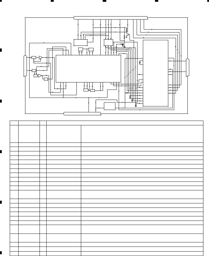
|
|
1 |
|
|
|
|
|
2 |
|
|
|
|
|
|
|
|
|
3 |
|
|
|
|
4 |
|
- FM/AM Tuner Unit (EW5) |
|
|
|
|
|
|
|
|
|
|
|
|
|
|
|
|
|
|
||||
|
|
|
|
|
|
|
7 |
6 |
|
|
13 |
|
5 |
10 |
9 |
8 |
11 |
14 |
18 |
19 |
20 |
21 |
|
A |
|
|
|
|
|
|
NC |
CE2 |
|
|
ROMVDD |
|
SL |
DI CK |
CE1 |
LDET |
DO |
RDS CK |
|
RDSDATA |
RDSLOCK |
RDSHSLK |
|
|
|
|
|
|
|
|
|
|
|
|
|
|
|
|
|
|
|
|
|
|
|
|
|
|
|
|
|
|
|
|
IC 3 EEPROM |
|
|
|
|
|
IC 5 |
|
|
|
|
|
|
|
|
||
|
|
|
|
|
|
|
|
5.0V |
|
|
|
|
|
5V t3.3V |
|
|
|
|
|
|
|
||
|
|
|
|
|
|
|
|
OSC |
|
|
LPF |
|
|
|
|
|
|
|
|
|
|
|
|
|
|
AM ANT |
FMRF |
|
|
|
|
|
|
|
|
|
|
|
|
|
|
|
|
|
|
|
|
|
|
|
|
|
|
|
|
|
|
|
|
|
|
|
|
|
|
|
|
|
|
|
|
|
|
1 |
ATT |
|
|
|
|
|
|
|
|
|
|
|
|
|
|
|
|
|
|
|
|
|
|
|
|
|
|
|
|
|
|
|
|
|
|
|
|
|
|
|
|
|
|
|
Rch 24 |
|
|
|
|
|
|
|
|
|
|
|
|
|
|
|
|
|
|
|
|
|
|
|
IC 2 |
|
|
FM ANT |
|
|
|
|
|
IC 1 |
|
|
|
|
|
|
|
|
|
|
|
|
|
2.5V |
|
|
|
|
|
|
|
|
|
|
|
|
|
|
|
|
|
|
|
|
|
|
|||
|
|
|
|
|
|
|
3.3V |
|
|
|
|
|
|
|
|
|
|
|
|
|
|
||
|
|
3 |
ATT |
|
|
|
|
|
|
|
|
|
|
|
|
|
|
|
|
|
|
Lch 23 |
|
|
|
FMRF |
|
|
|
MIXER, IF AM P |
|
|
|
|
|
|
|
|
|
|
|
||||||
B |
|
|
|
|
|
|
|
|
|
|
|
|
|
|
|
|
|
DET, FM MPX, |
|||||
|
|
|
|
|
|
|
|
|
|
|
|
|
|
|
|
|
|
|
|
|
|
||
|
|
|
RF adj |
|
|
|
|
|
|
|
|
|
|
|
|
|
|
|
|
|
RDS DECODER |
||
|
|
|
|
|
|
|
|
|
|
|
|
|
|
|
|
|
|
|
|
|
|
||
|
|
|
ANT adj |
|
|
|
|
|
|
|
|
|
|
|
|
|
|
|
|
|
|
|
|
|
|
|
|
|
|
|
|
|
T51 |
CF52 |
|
|
|
|
|
|
|
|
|
|
|
|
|
|
|
|
|
|
|
|
|
|
|
|
|
|
|
|
|
|
|
|
|
|
|
|
|
|
|
|
|
|
RFGND |
OSCGND |
DGND |
AUDIOGND |
NC |
VCC |
3.3VDD |
|
|
IC 4 |
|
|
|
|
|
|
|
||
|
|
|
|
|
|
|
|
|
|
|
|
|
3.3V |
3.3V t2.5V 2.5V |
|
|
|
|
|
|
|||
|
|
|
|
|
2 |
12 |
15 |
22 |
16 |
4 |
|
17 |
|
|
|
|
|
|
|
|
|
|
|
C |
No. |
Symbol |
|
I/O |
Explain |
|
|
|
|
|
|
|
|
|
|
|
|
|
|
|
|
|
|
1 |
AMANT |
|
I |
AM antenna input |
|
AM antenna input high impedance |
AMANT pin is connected with |
||||||||||||||||
|
|
|
|||||||||||||||||||||
|
|
|
|
|
|
|
|
|
an all antenna by way of 4.7 µH. (LAU type inductor) A series circuit |
||||||||||||||
|
|
|
|
|
|
|
|
|
including an inductor and a resistor is connected with RF ground for |
||||||||||||||
|
|
|
|
|
|
|
|
|
the countermeasure against the hum of power transmission line. |
||||||||||||||
|
2 |
RFGND |
|
|
RF ground |
|
|
|
Ground of antenna block |
|
|
|
|
|
|
||||||||
|
3 |
FMANT |
|
I |
FM antenna input |
|
Input of FM antenna 75 ohm Surge absorber(DSP-201M-S00B)is necessary. |
||||||||||||||||
|
4 |
VCC |
|
|
power supply |
|
|
The power supply for analog block. D.C 8.4 V ± 0.3 V |
|||||||||||||||
|
5 |
SL |
|
O |
signal level |
|
|
|
Output of FM/AM signals level |
|
|
|
|
|
|||||||||
|
6 |
CE2 |
|
I |
chip enable-2 |
|
|
Chip enable for EEPROM |
”Low” active |
||||||||||||||
|
7 |
NC |
|
|
non connection |
|
|
Not used |
|
|
|
|
|
|
|
|
|
|
|
||||
|
8 |
CE1 |
|
I |
chip enable-1 |
|
|
Chip enable for AF•RF |
”High” active |
|
|||||||||||||
D |
9 |
CK |
|
I |
clock |
|
|
|
Clock |
|
|
|
|
|
|
|
|
|
|
|
|
||
10 |
DI |
|
I |
data in |
|
|
|
Data input |
|
|
|
|
|
|
|
|
|
|
|
||||
|
|
|
|
|
|
|
|
|
|
|
|
|
|
|
|
||||||||
|
11 |
LDET |
|
O |
lock detector |
|
|
|
“Low” active |
|
|
|
|
|
|
|
|
|
|
||||
|
12 |
OSCGND |
|
osc ground |
|
|
|
Ground of oscillator block |
|
|
|
|
|
|
|||||||||
|
13 |
ROM_VDD |
|
power supply |
|
|
Power supply for EEPROM pin 13 is connected with a power supply of |
||||||||||||||||
|
|
|
|
|
|
|
|
|
micro computer. |
|
|
|
|
|
|
|
|
||||||
|
14 |
DO |
|
O |
data out |
|
|
|
Data output |
|
|
|
|
|
|
|
|
|
|
||||
|
15 |
DGND |
|
|
digital ground |
|
|
Ground of digital block |
|
|
|
|
|
|
|
||||||||
|
16 |
NC |
|
|
non connection |
|
|
Not used |
|
|
|
|
|
|
|
|
|
|
|
||||
|
17 |
VDD_3.3 |
|
power supply |
|
|
The power supply for digital block. 3.3 V ± 0.2 V |
||||||||||||||||
|
18 |
RDS_CK |
O |
RDS clock |
|
|
|
Output of RDS clock(2.5 V) |
|
|
|
|
|
|
|||||||||
|
19 |
RDS_DATA |
O |
RDS data |
|
|
|
Output of RDS data(2.5 V) |
|
|
|
|
|
|
|||||||||
E |
20 |
RDS_LOCK |
O |
RDS lock |
|
|
|
Output unit “High” active(2.5 V) (RDS_LOCK turns over by the |
|||||||||||||||
|
|
|
|
|
|
|
|
|
external transistor . “Low” active) |
|
|
|
|
||||||||||
|
21 |
RDS_HSLK |
O |
RDS high speed |
|
|
Output unit “High” active(2.5 V)(RDS_HSLK turns over by the |
||||||||||||||||
|
|
|
|
|
lock |
|
|
|
external transistor. “Low” active) |
|
|
|
|
||||||||||
|
22 |
AUDIOGND |
|
audio ground |
|
|
|
Ground of audio block |
|
|
|
|
|
|
|
||||||||
|
23 |
L ch |
|
O |
L channel output |
|
|
FM stereo “L-ch” signal output |
or |
|
AM audio output |
||||||||||||
|
24 |
R ch |
|
O |
R channel output |
|
FM stereo “R-ch” signal output |
or |
AM audio output |
||||||||||||||
F
20 |
DEH-4000UB/XS/EW5 |
|
1 |
|
2 |
|
3 |
|
4 |
|
|
5 |
|
6 |
|
7 |
|
8 |
|
- FM/AM Tuner Unit (ES, CN5) |
|
|
|
|
|
|
|
|
|
|
|
|
|
|
|
|
|
||
|
|
|
|
7 |
6 |
|
|
13 |
5 |
10 |
9 |
8 |
11 |
14 |
18 |
19 |
20 |
21 |
|
|
|
|
|
NC |
CE2 |
|
|
VDD |
SL |
DI CK |
CE1 |
NC |
DO |
NC |
NC |
NC |
NC |
A |
|
|
|
|
|
|
|
|
|
_ |
|
|
|
|
|
|
|
|
|
|
|
|
|
|
|
|
|
|
|
ROM |
|
|
|
|
|
|
|
|
|
|
|
|
|
|
|
|
|
|
|
|
|
|
|
|
|
|
|
|
|
|
|
|
|
|
|
IC 3 EEPROM |
|
|
|
IC 5 |
|
|
|
|
|
|
|
|
|||
|
|
|
|
|
5.0 V |
|
|
|
|
5 V |
3.3 V |
|
|
|
|
|
|
|
|
|
|
|
|
|
OSC |
|
|
LPF |
|
|
|
|
|
|
|
|
|
|
|
|
AM ANT |
FMRF |
|
|
|
|
|
|
|
|
|
|
|
|
|
|
|
|
|
|
|
|
|
|
|
|
|
|
|
|
|
|
|
|
|
|
|
|
|
1 |
AT T |
|
|
|
|
|
|
|
|
|
|
|
|
|
|
|
|
|
|
|
|
|
|
|
|
|
|
|
|
|
|
|
|
|
|
|
|
|
Rch 24 |
|
|
|
|
|
|
|
|
|
|
|
|
|
|
|
|
|
|
IC 2 |
|
|
FM ANT |
|
|
|
|
IC 1 |
|
|
|
|
|
|
|
|
|
|
|
2.5 V |
|
|
|
|
|
|
|
|
|
|
|
|
|
|
|
|
|
|
|
||
|
|
|
|
|
3.3 V |
|
|
|
|
|
|
|
|
|
|
|
|
|
|
3 |
AT T |
|
|
|
|
|
|
|
|
|
|
|
|
|
|
|
|
Lch 23 |
|
FMRF |
|
|
MIXER, IF AM P |
|
|
|
|
|
|
|
|
|
|
||||||
|
|
|
|
|
|
|
|
|
|
|
|
|
DET, FM MPX |
B |
|||||
|
|
|
|
|
|
|
|
|
|
|
|
|
|
|
|
|
|
||
|
|
RF adj |
|
|
|
|
|
|
|
|
|
|
|
|
|
|
|
|
|
|
|
|
|
|
|
|
|
|
|
|
|
|
|
|
|
|
|
|
|
|
ANT adj |
|
|
|
|
|
|
|
|
|
|
|
|
|
|
|
|
|
|
|
|
|
|
|
|
T51 |
CF52 |
|
|
|
|
|
|
|
|
|
|
|
|
|
|
|
|
|
|
|
|
|
|
|
|
|
|
|
|
|
|
|
|
|
|
RFGND |
OSCGND |
DGND |
AUDIOGND |
NC |
VCC |
VDD3.3 |
3.3 V |
|
|
|
2.5 V |
|
|
|
|
|
|
|
|
2 |
12 |
15 |
22 |
16 |
4 |
17 |
|
|
|
|
|
|
|
|
|
|
|
No. |
Symbol |
I/O |
Explain |
|
|
|
C |
||
1 |
AMANT |
I |
AM antenna input |
AM antenna input high impedance AMANT pin is connected with |
|||||
|
|
||||||||
|
|
|
|
an all antenna by way of 4.7 µH. (LAU type inductor) A series circuit |
|
|
|||
|
|
|
|
including an inductor and a resistor is connected with RF ground for |
|
|
|||
|
|
|
|
the countermeasure against the hum of power transmission line. |
|
|
|||
2 |
RFGND |
|
RF ground |
Ground of antenna block |
|
|
|
|
|
3 |
FMANT |
I |
FM antenna input |
Input of FM antenna 75 ohm Surge absorber (DSP-201M-S00B) is necessary. |
|
|
|||
4 |
VCC |
|
power supply |
The power supply for analog block. D.C 8.4 V ± 0.3 V |
|
|
|||
|
|
|
|||||||
5 |
SL |
O |
signal level |
Output of FM/AM signals level |
|
|
|
|
|
6 |
CE2 |
I |
chip enable-2 |
Chip enable for EEPROM ”Low” active |
|
|
|||
7 |
NC |
|
non connection |
Not used |
|
|
|
|
|
8 |
CE1 |
I |
chip enable-1 |
Chip enable for AF•RF ”High” active |
|
|
|||
9 |
CK |
I |
clock |
Clock |
|
|
D |
||
10 |
DI |
I |
data in |
Data input |
|
|
|||
|
|
|
|
||||||
11 |
NC |
|
non connection |
Not used |
|
|
|
|
|
12 |
OSCGND |
|
osc ground |
Ground of oscillator block |
|
|
|
|
|
13 |
ROM_VDD |
|
power supply |
Power supply for EEPROM pin 13 is connected with a power supply of |
|
|
|||
|
|
|
|
micro computer. |
|
|
|
|
|
14 |
DO |
O |
data out |
Data output |
|
|
|
|
|
|
|
|
|
||||||
15 |
DGND |
|
digital ground |
Ground of digital block |
|
|
|
|
|
16 |
NC |
|
non connection |
Not used |
|
|
|
|
|
17 |
VDD_3.3 |
|
power supply |
The power supply for digital block. 3.3 V ± 0.2 V |
|
|
|||
18 |
NC |
|
non connection |
Not used |
|
|
|
|
|
19 |
NC |
|
non connection |
Not used |
|
|
|
|
|
20 |
NC |
|
non connection |
Not used |
|
|
E |
||
21 |
NC |
|
non connection |
Not used |
|
|
|
|
|
22 |
AUDIOGND |
|
audio ground |
Ground of audio block |
|
|
|
|
|
23 |
L ch |
O |
L channel output |
FM stereo “L-ch” signal output |
or |
AM audio output |
|
|
|
24 |
R ch |
O |
R channel output |
FM stereo “R-ch” signal output |
or |
AM audio output |
|
|
|
|
|
|
|
|
|
|
|
|
|
|
|
|
|
|
|
|
|
|
|
F
|
|
|
|
DEH-4000UB/XS/EW5 |
|
|
21 |
|
||
|
|
|
|
|
|
7 |
|
|
||
|
5 |
|
6 |
|
|
|
8 |
|
||
|
|
|
|
|
||||||

1
- LCD(YAW5091)
A
B
C
D
E
SEGMENT
F
22
1
|
2 |
|
3 |
|
4 |
|
DEH-4000UB/XS/EW5
|
2 |
|
3 |
|
4 |
|
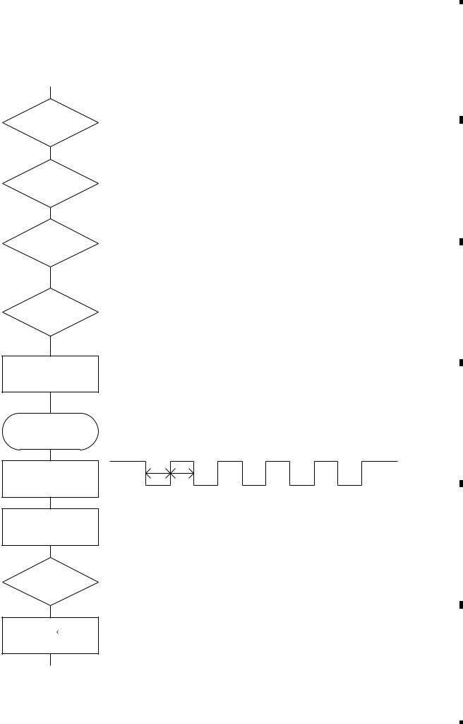
|
5 |
|
6 |
|
7 |
|
8 |
5. DIAGNOSIS
5.1 OPERATIONAL FLOWCHART
Power ON
Vcc = 5 V
Pin 16
bsens
Pin 18
bsens = L
asens
Pin 75
asens = L
DSENS
Pin 19
DSENS = L
ASENBO H
H
Pin 40
SWVDD H
H
Pin 49
Source keys operative
Starts communication with Grille microcomputer.
300 ms
300 ms
In case of the above signal, the communication with Grille microcomputer may fail.
If the time interval is not 300 msec, the oscillator may be defective.
Source ON
SYSPW H
Pin 48
Completes power-on operation.(After that, proceed to each source operation.)
|
|
|
|
DEH-4000UB/XS/EW5 |
|
|
23 |
||
|
|
|
|
|
|
7 |
|
||
|
5 |
|
6 |
|
|
|
8 |
||
|
|
|
|
||||||
A
B
C
D
E
F

1  2
2  3
3  4
4
5.2 ERROR CODE LIST
- Error Messages
A |
If a CD is not operative or stopped during operation due to an error, the error mode is turned on and cause(s) of |
|
the error is indicated with a corresponding number. This arrangement is intended at reducing nonsense calls from |
||
|
||
|
the users and also for facilitating trouble analysis and repair work in servicing. |
|
|
(1) Basic Indication Method |
|
|
1) When SERRORM is selected for the CSMOD (CD mode area for the system), error codes are written to DMIN |
|
|
||
|
(minutes display area) and DSEC (seconds display area). The same data is written to DMIN and DSEC. DTNO |
|
|
remains in blank as before. |
2) Head unit display examples
B |
Depending on display capability of LCD used, display will vary as shown below. xx contains the error number. |
|||||||||||
|
|
|||||||||||
|
|
|
|
|
8-digit display |
|
6-digit display |
4-digit display |
||||
|
|
|
|
|
|
|
|
|
|
|
|
|
|
|
|
|
|
ERROR-xx |
|
|
ERR-xx |
|
|
E-xx |
|
|
|
|
|
|
|
|
|
|
|
|
|
|
|
|
(2) Error Code List |
|
|
|
|
|
|
|
|
||
|
|
|
|
|
|
|
|
|
|
|||
|
|
|
|
|
|
|
|
|
|
|||
|
|
Code |
Class |
Displayed error code |
Description of the code and potential cause(s) |
|||||||
|
|
10 |
Electricity |
Carriage Home NG |
CRG can't be moved to inner diameter. |
|
|
|||||
|
|
|
|
|
SERVO LSI Com- |
CRG can't be moved from inner diameter. |
|
|
||||
C |
|
|
|
munication Error |
-> Failure on home switch or CRG move mechanism. |
|||||||
|
|
|
|
|
Communication error between microcomputer and SERVO LSI. |
|||||||
|
|
|
|
|
|
|
||||||
|
|
11 |
Electricity |
Focus Servo NG |
Focusing not available. |
|
|
|||||
|
|
|
|
|
|
|
-> Stains on rear side of disc or excessive vibrations on REWRITABLE. |
|||||
|
|
12 |
Electricity |
Spindle Lock NG |
Spindle not locked. Sub-code is strange (not readable). |
|||||||
|
|
|
|
|
Subcode NG |
-> Failure on spindle, stains or damages on disc, or excessive vibrations. |
||||||
|
|
|
|
|
||||||||
|
|
|
|
|
|
|
A disc not containing CD-R data is found. |
|
|
|||
|
|
|
|
|
|
|
Turned over disc are found, though rarely. |
|||||
|
|
|
|
|
|
|
CD signal error. |
|
|
|||
|
|
17 |
Electricity |
Setup NG |
AGC protection doesn't work. Focus can be easily lost. |
|||||||
D |
|
|
|
|
|
-> Damages or stains on disc, or excessive vibrations on REWRITABLE. |
||||||
|
|
30 |
Electricity |
SearchTime Out |
Failed to reach target address. |
|
|
|||||
|
|
|
|
|
|
|
-> CRG tracking error or damages on disc. |
|
|
|||
|
|
44 |
Electricity |
ALL Skip |
Skip setting for all track. |
|
|
|||||
|
|
|
|
|
|
|
(CD-R/RW) |
|
|
|||
|
|
50 |
Mechanism |
CD On Mech Error |
Mechanical error during CD ON. |
|
|
|||||
|
|
|
|
|||||||||
|
|
|
|
|
|
|
-> Defective loading motor, mechanical lock and mechanical sensor. |
|||||
|
|
A0 |
System |
Power Supply NG |
Power (VD) is ground faulted. |
|
|
|||||
|
|
|
|
|
|
|
-> Failure on SW transistor or power supply (failure on connector). |
|||||
E |
Remarks: Mechanical errors are not displayed (because a CD is turned off in these errors). |
|||||||||||
|
|
|
|
|
|
|
|
|
|
|
||
|
|
|
UnreadableTOC does not constitute an error. An intended operation continues in this case. |
|||||||||
|
|
|
Upper digits of an error code are subdivided as shown below: |
|
|
|||||||
|
|
|
1x: Setup relevant errors, 3x: Search relevant errors, Ax: Other errors. |
|
|
|||||||
|
|
|
|
|
|
|
|
|
|
|
|
|
|
|
|
|
|
|
|
|
|
|
|
|
|
F
24 |
DEH-4000UB/XS/EW5 |
|
1 |
|
2 |
|
3 |
|
4 |
|
Loading...