

Page 1
MANUEL D’INSTALLATION
INSTALLATION MANUAL
AVIC-X1BT
This product conforms to new cord colours.
Los colores de los cables de este producto se conforman con un nuevo código de colores.
Dieses Produkt entspricht den neuen kabelfarben.
Le code de couleur des câbles utilisé pour ce produit est
nouveau.
Questo prodotto è conforme ai nuovi codici colori.
De kleuren van de snoeren van dit toestel zijn gewijzigd.
English
Español
Deutsch
Français
Italiano
Nederlands
Page 2

1
IMPORTANT INFORMATION
ABOUT YOUR NEW NAVIGATION SYSTEM AND THIS MANUAL
• The navigation features of this product (and rear view camera option if purchased) is intended solely as an aid to you in the operation of your vehicle. It is
not a substitute for your attentiveness, judgement and care when driving.
• Never use this navigation system to route to hospitals, police stations, or similar
facilities in an emergency, Please call the appropriate emergency number.
• Do not operate this navigation system (or the rear view camera option if purchased) if doing so in any way will divert your attention from the safe operation
of your vehicle. Traffic restrictions and advisories currently in force should
always take precedence over guidance given by this product. Always obey current
traffic restrictions, even if this product provides contrary advice.
• This manual explains how to install this navigation system in your vehicle.
Operation of this navigation system is explained in the separate Operation
Manual or Hardware Manual for the navigation system.
• Do not install this product where it may (i) obstruct the driver’s vision, (ii) impair
the performance of any of the vehicle’s operating systems of safety features,
including airbags, hazard lamp buttons or (iii) impair the driver’s ability to safely
operate the vehicle. In some cases, it may not be possible to install this product
because of the vehicle type or the shape of the vehicle interior.
Page 3

English
Español
Deutsch
Français
Italiano
Nederlands
IMPORTANT INFORMATION .................... 1
ABOUT YOUR NEW NAVIGATION
SYSTEM AND THIS MANUAL .............. 1
IMPORTANT SAFEGUARDS .................... 3
PLEASE READ ALL OF THESE
INSTRUCTIONS REGARDING
YOUR NAVIGATION
SYSTEM AND RETAIN THEM
FOR FUTURE REFERENCE .................... 3
Connecting the System ............................ 4
-
Before installing this product
-
To prevent damage
-
Parts supplied
Connecting the system ...................................... 7
Connecting the power cord (1) .......................... 9
Connecting the power cord (2) ........................ 11
When connecting to separately sold power
amp .......................................................... 13
When connecting a Rear view camera ............ 15
When connecting the external video component
and the display .......................................... 16
-
When using a display connected to rear video
output
Installation ................................................ 17
To guard against electromagnetic
interference .............................................. 18
Before installing .............................................. 18
Installing this product ...................................... 19
-
Installation notes
-
Parts supplied
-
Installing the Hide-away unit
-
DIN Front/Rear-mount
-
DIN Front-mount
-
DIN Rear-mount
-
Fixing the front panel
-
Installing the Bluetooth adapter
-
When installing the microphone on the sun
visor
-
When installing the microphone on the steer-
ing column
Adjusting the microphone angle ...................... 28
Installing the GPS aerial .................................. 29
-
Installation notes
-
Parts supplied
-
When installing the aerial inside the vehicle
(on the rear shelf)
-
When installing the aerial outside the vehicle
(on the body)
After Installing this Product.................... 32
2
Contents
Page 4

IMPORTANT SAFEGUARDS
3
PLEASE READ ALL OF THESE INSTRUCTIONS REGARDING YOUR
NAVIGATION SYSTEM AND RETAIN THEM FOR FUTURE REFERENCE
1. Read this manual fully and carefully before installing your navigation system.
2. Keep this manual handy for future reference.
3. Pay close attention to all warnings in this manual and follow the instructions carefully.
4. This navigation system may in certain circumstances display erroneous information regarding the position of your vehicle, the distance of objects shown on the
screen, and compass directions. In addition, the system has certain limitations,
including the inability to identify one-way streets, temporary traffic restrictions
and potentially unsafe driving areas. Please exercise your own judgement in the
light of actual driving conditions.
5. As with any accessory in your vehicle’s interior, the navigation system should not
divert your attention from the safe operation of your vehicle. If you experience
difficulty in operating the system or reading the display, please make adjustments
while safely parked.
6. Please remember to wear your seat belt at all times while operating your vehicle.
If you are ever in an accident, your injuries can be considerably more severe if
your seat belt is not properly fastened.
7. Certain countries laws may restrict the placement and use of navigation systems
in your vehicle. Please comply with all applicable laws and regulations in the
installation and operation of your navigation system.
Do not attempt to install or service your navigation system by yourself.
Installation or servicing of the navigation system by persons without training and
experience in electronic equipment and automotive accessories may be dangerous
and could expose you to the risk of electric shock or other hazards.
Page 5

English
Español
Deutsch
Français
Italiano
Nederlands
4
Connecting the System
• Pioneer does not recommend that you install your navigation system yourself. We
recommend that only authorised Pioneer service personnel, who have special training and experience in mobile electronics, set up and install this product. NEVER
SERVICE THIS PRODUCT YOURSELF. Installing or servicing this product and
its connecting cables may expose you to the risk of electric shock or other hazards,
and can cause damage to the navigation system that is not covered by warranty.
• If you decide to perform the installation yourself, and have special training and
experience in the mobile electronics installations, please carefully follow all of the
steps in the Installation Manual.
• Secure all wiring with cable clamps or electrical tape. Do not allow any bare wiring
to remain exposed.
• Do not directly connect the yellow lead of this product to the vehicle battery. If the
lead is directly connected to the battery, engine vibration may eventually cause the
insulation to fail at the point where the wire passes from the passenger compartment into the engine compartment. If the yellow lead’s insulation tears as a result
of contact with metal parts, short-circuiting can occur, resulting in considerable
danger.
• It is extremely dangerous to allow the GPS aerial cable or microphone cable to
become wound around the steering column or gearstick. Be sure to install this
product, its cables, and wiring away in such a way that they will not obstruct or
hinder driving.
• Make sure that the cables and wires are routed and secured so they will not interfere with or become caught in any of the vehicle’s moving parts, especially the
steering wheel, gearstick, handbrake, sliding seat tracks, doors, or any of the vehicle’s controls.
• Do not route wires where they will be exposed to high temperatures. If the insulation heats up, wires may become damaged, resulting in a short circuit or malfunction and permanent damage to the product.
• Do not cut the GPS aerial cable to shorten it or use an extension to make it longer.
Altering the aerial cable could result in a short circuit or malfunction.
• Do not shorten any leads. If you do, the protection circuit (fuse holder, fuse resister
or filter, etc.) may fail to work properly.
• Never feed power to other electronic products by cutting the insulation of the
power supply lead of the navigation system and tapping into the lead. The current
capacity of the lead will be exceeded, causing overheating.
• The black lead is earth. Please earth this lead separately from the earth of highcurrent products such as power amps. Do not earth more than one product together with the earth from another product. For example, you must separately earth
any amplifier unit away from the earth of the Hide-away unit. Connecting earths
together can cause a fire and/or damage the products if their earths became
detached.
Page 6
5
Connecting the System
Before installing this product
• This product is for vehicles with a 12-volt battery and negative earthing. Check the battery voltage of your vehicle before installation.
To prevent damage
• When disconnecting a connector, pull the connector itself. Do not pull the lead, as you
may pull it out of the connector.
• This product cannot be installed in a vehicle that does not have an ACC (accessory)
position on the ignition switch.
• To avoid short-circuiting, cover the disconnected lead with insulating tape. It is especially important to insulate all unused speaker leads, which if left uncovered may cause a
short circuit.
• Attach the connectors of the same colour to the corresponding coloured port, i.e., blue
connector to the blue port, black to black, etc.
• Refer to the owner’s manual for details on connecting the power amp and other units,
then make connections accordingly.
• When replacing the fuse, be sure to only use a fuse of the rating prescribed on the fuse
holder.
• Since a unique BPTL circuit is employed, do not directly earth the ≠ side of the speaker
lead or connect the ≠ sides of the speaker leads together. Be sure to connect the ≠ side
of the speaker lead to the ≠ side of the speaker lead on the display unit.
• If the RCA pin jack on this product will not be used, do not remove the caps attached to
the end of the connector.
• Never connect speakers with an output rating of less than 50 W channel or impedance
outside of the 4 ohms to 8 ohms specifications to your navigation system. Connecting
speakers with output and/or impedance values other than those noted here may result in
the speakers catching fire, emitting smoke, or becoming damaged.
• When the auto aerial function is used by connecting the blue lead to the vehicle
with the auto aerial function, either turning off the ignition switch or detaching
the front panel will retract the auto aerial of the vehicle.
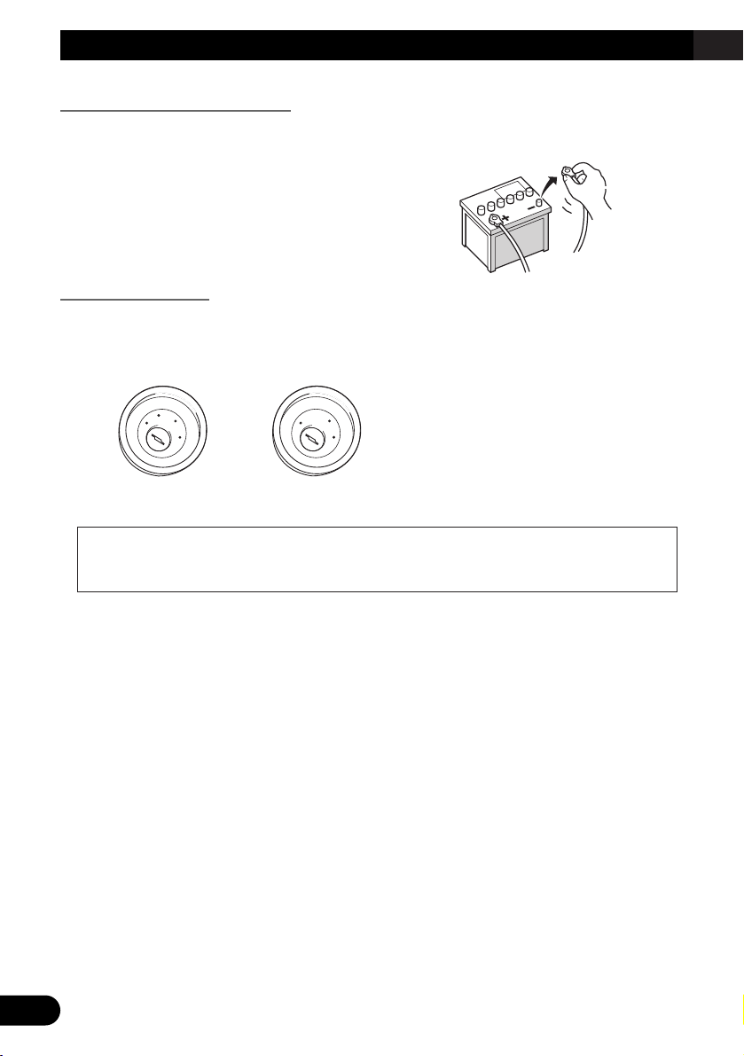
No ACC positionACC position
• To avoid shorts in the electrical system, be sure to disconnect the (–)
battery cable before beginning
installation.
C
C
A
O
F
N
F
O
S
T
A
R
T
O
F
N
F
O
S
T
A
R
T
Page 7
English
Español
Deutsch
Français
Italiano
Nederlands
6
• When the ignition switch is turned on (ACC ON), a control signal is output through the
blue/white lead. Connect to an external power amp’s system remote control terminal
(max. 300 mA 12 V DC). The control signal is output through the blue/white lead, even
if the front panel is detached, or the audio source is switched off.
• When an external power amp is being used with this system, be sure not to connect the
blue lead to the amp’s power terminal. Likewise, do not connect the blue lead to the
power terminal of the auto aerial. Such connection could cause excessive current drain
and malfunction as well as damage to the auto aerial of the vehicle.
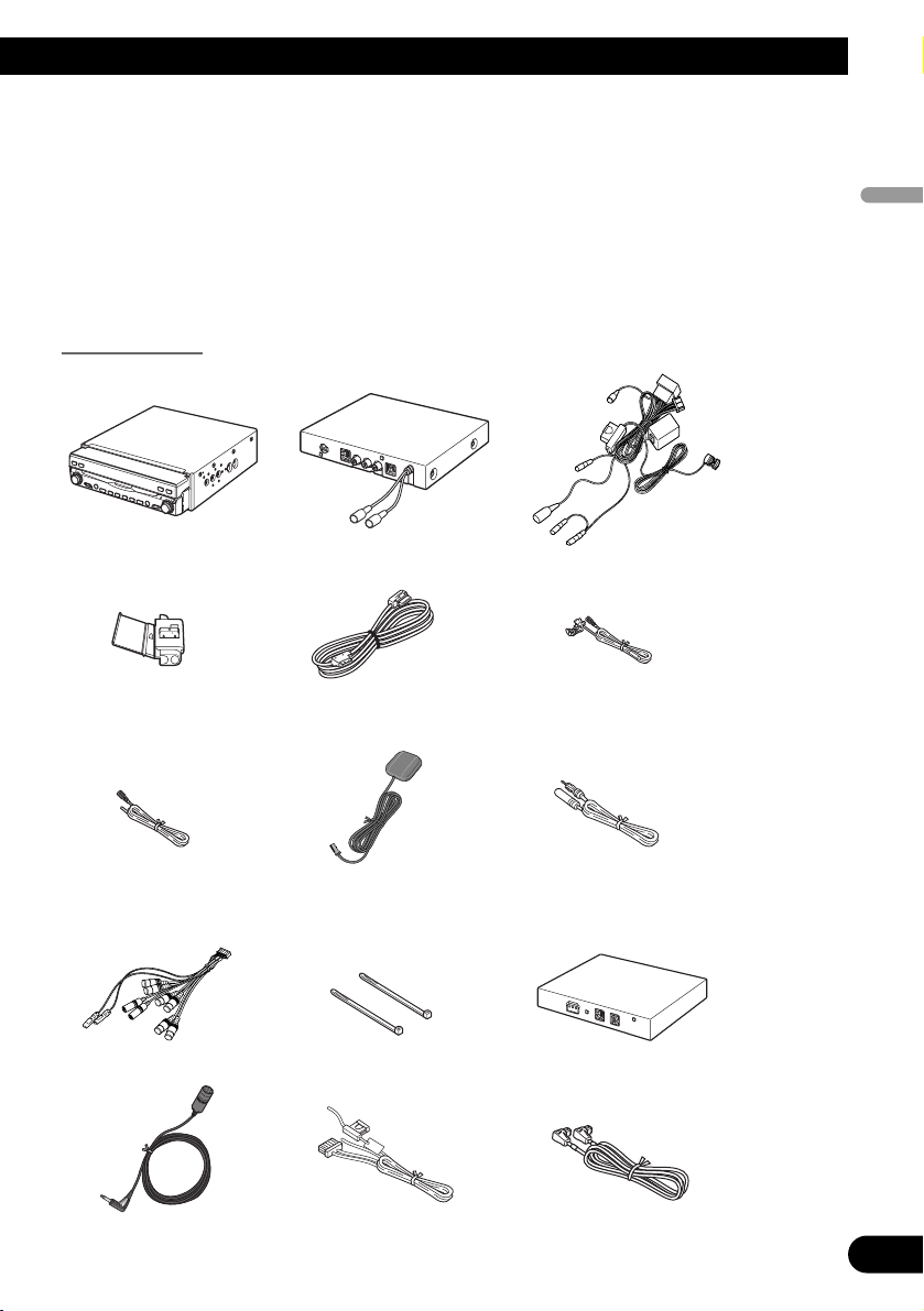
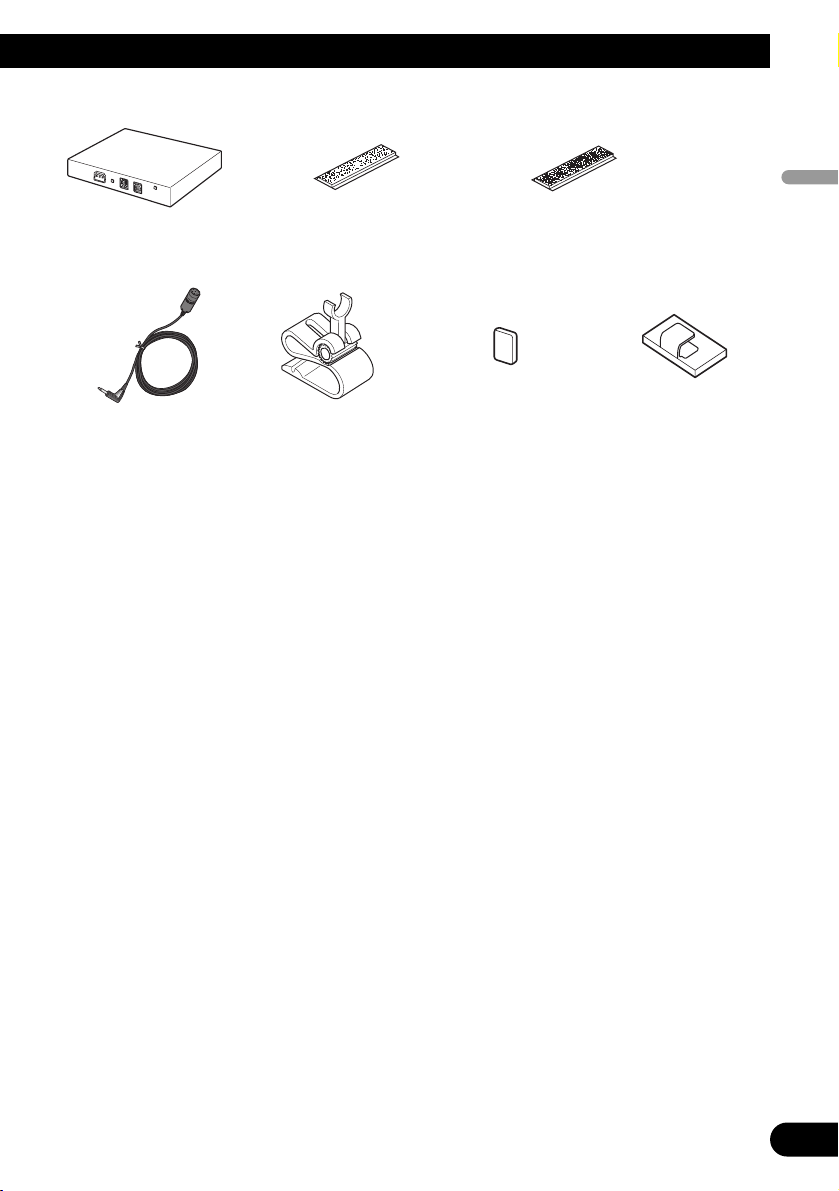
Parts supplied
IP-BUS cablePower cordMicrophone
Bluetooth adapterLock tieSystem extension connector
Extension aerial cableGPS aerialExtension lead
(for speed signal)
Extension lead
(for reverse signal)
30-pin cableConnector
Power cordHide-away unitDisplay unit
Page 8
7
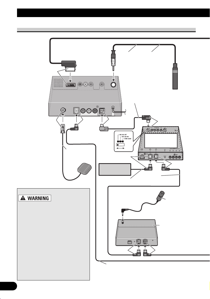
Connecting the System
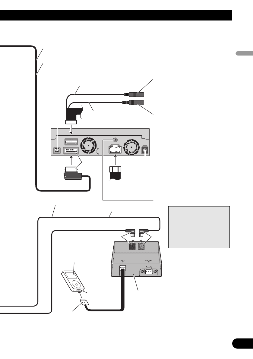
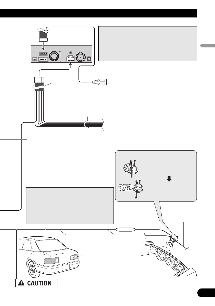
Connecting the system
Yellow
Hide-away unit
Light grey
Blue
Blue
AV-BUS cable
(supplied with
TV tuner)
Extension
aerial cable
(supplied)
3 m
When installing
the Hide-away unit
in the boot, etc.,
the extension cable
(e.g. CD-SC300E)
(sold separately)
is required.
Multi-CD player
5 m
IP-BUS cable
GPS aerial
(sold separately)
Blue
Hide-away TV tuner
(e.g. GEX-P5700TVP)
(sold separately)
Black
Black
IP-BUS cable
(supplied with TV tuner)
IP-BUS cable (supplied with iPod adapter)
*:
In order to operate the navigation system by
voice, the microphone in the voice recognition
kit (e.g. CD-VC1) (sold separately) is required.
Bluetooth
adapter
(CD-BT10)
Blue
Black
Microphone*
(supplied)
• To avoid the risk of accident and the
potential violation of applicable
laws, this product should never be
used while the vehicle is being driven except for navigation purposes.
And, also Rear Displays should not
be in a location where it is a visible
distraction to the driver.
• In some countries or states the viewing of images on a display inside a
vehicle even by persons other than
the driver may be illegal. Where
such regulations apply they must be
obeyed and this product’s video
source or TV features should not be
used.
Page 9
8
English
Español
Deutsch
Français
Italiano
Nederlands
IP-BUS cable
(supplied)
Dock connector
port
Dock connector
(supplied with iPod adapter)
iPod with
Dock connector
iPod adapter
(e.g. CD-IB100)
(sold separately)
Blue
Black
3 m
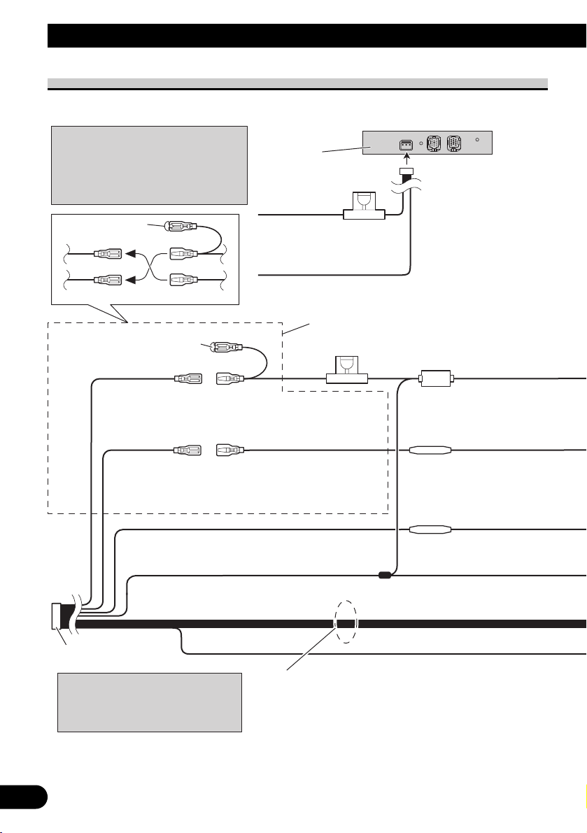
Yellow
DIGITAL OUT*
G.SP (Guidance speaker output)*
MIC INPUT
The microphone in the voice
recognition kit (e.g. CD-VC1)
(sold separately) is connected
when the voice recognition
function is used.
3 m
30-pin cable
Power cord
WIRED REMOTE INPUT
Please see the Instruction
Manual for the Wired Remote
Control adapters (sold separately).
Display unit
20 cm
20 cm
EXTENSION port
Not used.
*: This terminal is intended
to support future equipment and should not be
used if you are using
this product by itself.
Page 10
9
Connecting the System
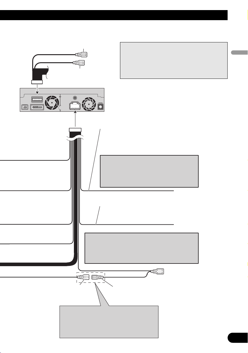
Connecting the power cord (1)
Connect leads of the same
colour to each other.
Cap (*1
When not using this terminal,
do not remove the cap.
Fuse (10 A)
Yellow
To terminal always supplied
with power regardless of
ignition switch position.
Black (earth)
To vehicle (metal) body.
Bluetooth
adapter
(CD-BT10)
Note:
Depending on the kind of vehicle, the
function of *3 and *5 may be different.
In this case, be sure to connect *2 to *5
and *4 to *3.
Fuse (2 A)
)
ISO connector
Yellow (*2)
To terminal always supplied
with power regardless of
ignition switch position.
Red (*4)
To electric terminal controlled
by ignition switch (12 V DC)
ON/OFF.
Yellow (*3)
Back-up
(or accessory)
Red (*5)
Accessory
(or back-up)
Black (earth)
To vehicle (metal) body.
Orange/white
To lighting switch terminal.
Note:
In some vehicles, the ISO connector
may be divided into two. In this case,
be sure to connect to both connectors.
Fuse resistor
Fuse resistor
Speaker leads
White: Front left +
White/black: Front left ≠
Grey: Front right +
Grey/black: Front right ≠
Green: Rear left + or Subwoofer +
Green/black: Rear left ≠ or Subwoofer ≠
Violet: Rear right + or Subwoofer +
Violet/black: Rear right ≠ or Subwoofer ≠
*1
*2
*4
*3
*5
Page 11
10
English
Español
Deutsch
Français
Italiano
Nederlands
GUIDE ON
SYSTEM REMOTE
CONTROL
Blue (*7)
ToAuto-aerial relay control terminal
(max. 300 mA 12 V DC).
Blue (*6)
Y
Light green
ellow/black
If you use equipment with a mute function (e.g. cellular
telephones), connect that equipment to the Audio Mute
lead. If not, keep the Audio Mute lead free of any
connections.
Note:
The pin position of the ISO connector will differ
depending on the type of vehicle. Connect *6 and
*7 when Pin 5 is an aerial control type. In other
types of vehicle, never connect *6 and *7.
When the auto aerial function is used by connecting
the blue lead to the vehicle with the auto aerial function,
either turning off the ignition switch or detaching the
front panel will retract the auto aerial of the vehicle.
Note:
Note:
Audio source will be set to mute or attenuate,
while the voice guidance of the navigation
will not be muted or attenuated.
For details, see the Operation Manual.
Note:
Cords for this product and those for other products
may be different colours even if they have the same
function. When connecting this product to another
product, refer to the supplied manuals of both products and connect cords that have the same function.
Display unit
☞
See Page 11.
☞
See Page 12.
Page 12
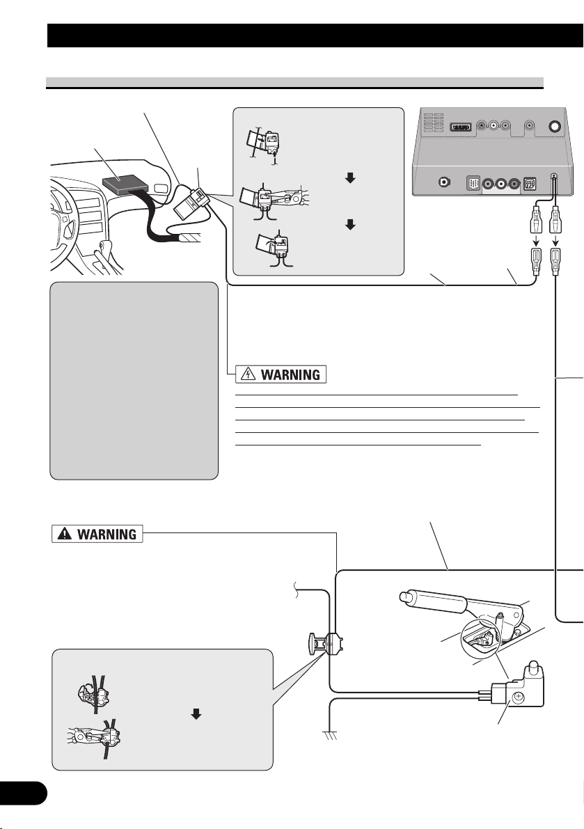
Pink (CAR SPEED SIGNAL INPUT)
The mobile navigation system is connected here to detect the distance
the vehicle travels. Always connect the vehicle’s speed detection
circuit or the ND-PG1 speed pulse generator, sold separately. Failure
to make this connection will increase errors in the location display.
IMPROPER CONNECTION MAY RESULT IN SERIOUS
DAMAGE OR INJURY INCLUDING ELECTRICAL SHOCK,
AND INTERFERENCE WITH THE OPERATION OF THE
VEHICLE’S ANTILOCK BRAKING SYSTEM, AUTOMATIC
GEARBOX AND SPEEDOMETER INDICATION.
Light green
Used to detect the ON/OFF status of the handbrake. This lead must be
connected to the power supply side of the handbrake switch. If this
connection is made incorrectly or omitted, certain functions of
your navigation system will be unusable.
LIGHT GREEN LEAD AT POWER
CONNECTOR IS DESIGNED TO DETECT
PARKED STATUS AND MUST BE
CONNECTED TO THE POWER SUPPLY SIDE
OF THE HANDBRAKE SWITCH. IMPROPER
CONNECTION OR USE OF THIS LEAD MAY
VIOLATE APPLICABLE LAW AND MAY
RESULT IN SERIOUS INJURY OR DAMAGE.
11
Connecting the System
Connecting the power cord (2)
Notes:
• The position of the speed detection circuit depends on the vehicle model. For details, consult
your authorised Pioneer dealer or
an installation professional.
If connection to the speed detection circuit is too difficult, connect the separately sold ND-PG1
speed pulse generator to the pink
lead.
• The position of the handbrake
switch depends on the vehicle
model. For details, consult the
vehicle owner’s manual or dealer.
Connection method
Clamp the handbrake switch
power supply side lead.
Clamp firmly with
needle-nosed pliers.
Power supply side
Earth side
Handbrake switch
Hide-away unit
Speed detection circuit lead
Vehicle injection
computer
Connector
Pass the extension cord
and the lead for the speed
detection circuit through
this hole.
Clamp firmly with
needle-nosed
pliers.
Close the cover.
Connection method
Extension lead
(for speed signal)
5 m
Page 13
Be sure to use only the supplied extension lead. Use of another lead could
cause fire, smoke and/or damage this product.
12
English
Español
Deutsch
Français
Italiano
Nederlands
Note:
Cords for this product and those for other products may
be different colours even if they have the same function. When connecting this product to another product,
refer to the supplied Installation manuals of both products and connect cords that have the same function.
Power cord
Black, Orange/white, Red, Yellow
☞
See Page 9.
Yellow/black (GUIDE ON)
When combining this navigation system with the
other Pioneer audio unit for the vehicle, if the vehicle
stereo has yellow/black leads, connect them to those
leads. In this way, the vehicle stereo is automatically
muted to reduce the vehicle stereo volume when;
• the guidance audio is output.
• the cellular phone is used via Bluetooth adapter.
• you operate the system by voice.
Violet/white (REVERSEGEAR SIGNAL INPUT)
This is connected so that the navigation system can
detect whether the vehicle is moving forwards or
backwards. Connect the violet/white lead to the
lead whose voltage changes when the reverse gear
is engaged. Unless connected, the sensor may not
detect your vehicle travelling forward/backward
properly, and thus the position of your vehicle
detected by the sensor may be misaligned from the
actual position.
Connection method
Clamp the reversing lamp
lead.
Clamp firmly with
needle-nosed pliers.
Reversing lamp lead
Fuse resistor
Check the position of your vehicle’s reversing lamp (the one that
lights up when the gearstick is in
reverse [R]) and find the reversing
lamp lead in the boot.
Display unit
Extension lead
(for reverse signal)
5 m
Note:
When you use the ND-PG1 speed pulse generator
(sold separately), please make sure to connect it.
When you use a rear view camera, please make
sure to connect it. Otherwise you cannot switch to
rear view camera picture.
☞
See Page 15.
Page 14
13
Connecting the System
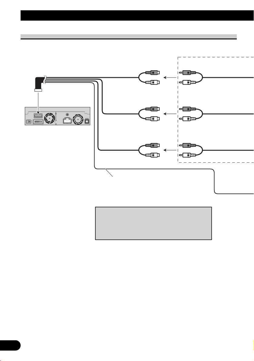
Display unit
Front output
(FRONT OUTPUT)
Subwoofer output
or non-fading output
(SUBWOOFER OUTPUT or
NON-FADING OUTPUT)
Rear output
(REAR OUTPUT)
15 cm
20 cm
15 cm
Blue/white
To system control terminal of the power amp
(max. 300 mA 12 V DC).
Do not connect this lead to Auto-aerial control
terminal.
Note:
When a subwoofer is connected to this product instead
of a rear speaker, change the rear output setting in
the Initial Setting. (Refer to the Operation Manual.)
The subwoofer output of this product is monaural.
When connecting to separately sold power amp
Page 15
14
English
Español
Deutsch
Français
Italiano
Nederlands
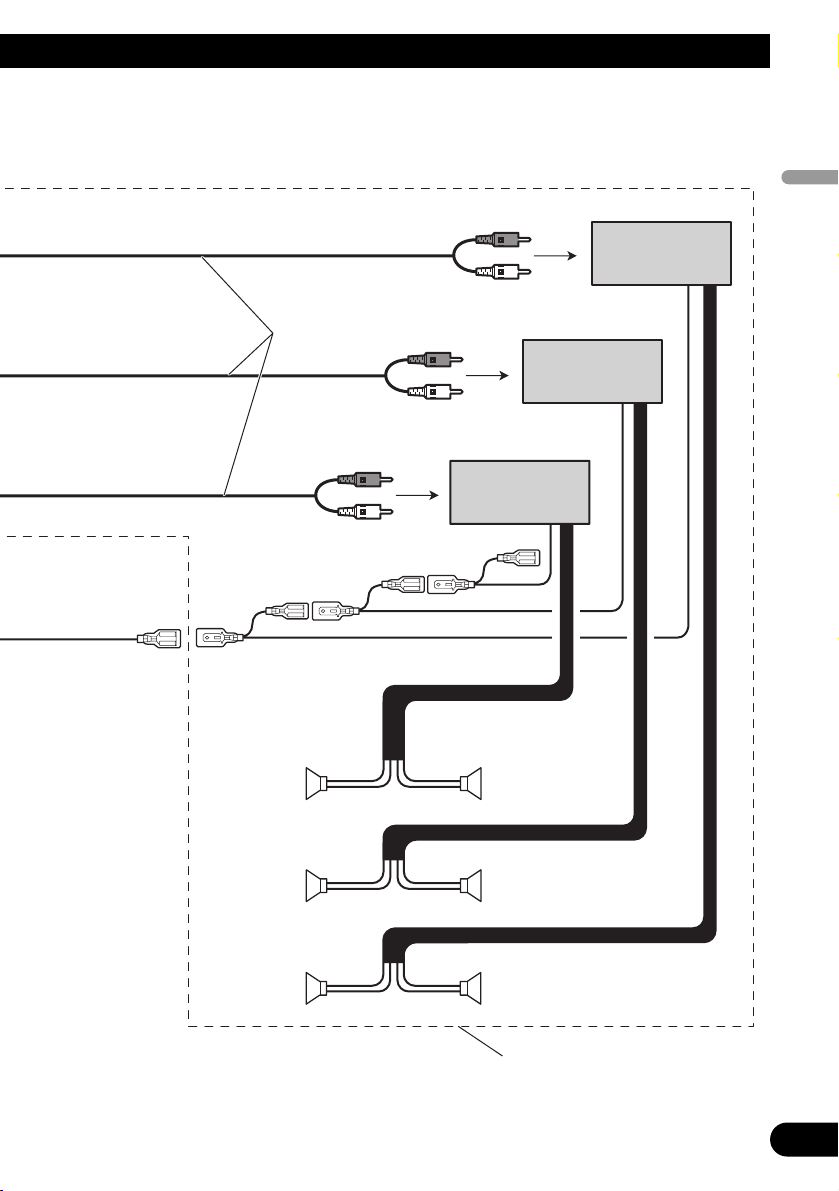
Power amp
(sold separately)
Power amp
(sold separately)
Power amp
(sold separately)
+
≠
+
≠
+
≠
+
≠
+
≠
+
≠
System remote control
RCA cables
(sold separately)
Front speaker
Rear speaker
Subwoofer
Front speaker
Rear speaker
Subwoofer
Left Right
Perform these connections when using
the optional amplifier.
Page 16
15
Connecting the System
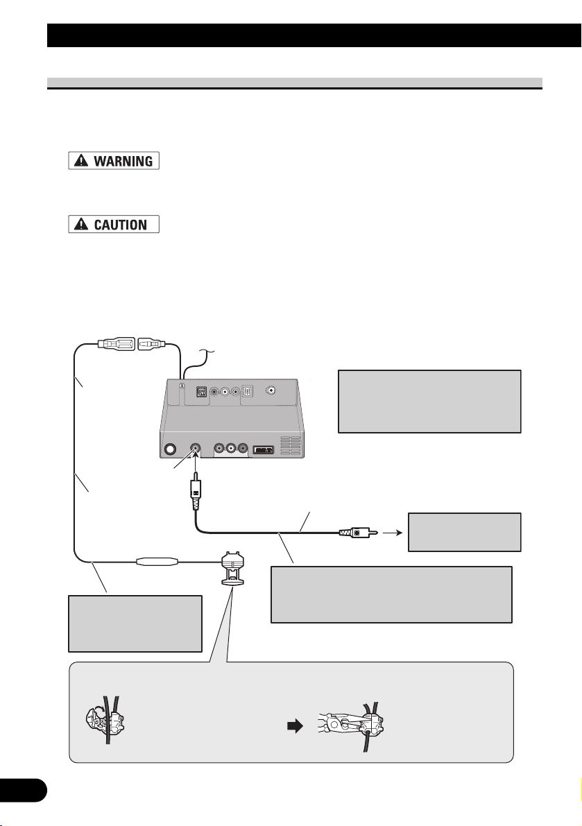
When connecting a Rear view camera
When using this product with a rear view camera, automatic switching to video from a rear
view camera is possible when the gear shift is moved to REVERSE (R) position.
Rear view mode also allows you to check what is behind you while driving.
USE INPUT ONLY FOR REVERSE OR MIRROR IMAGE REAR VIEW CAMERA. OTHER USE
MAY RESULT IN INJURY OR DAMAGE.
• The screen image may appear reversed.
• The rear view camera function is to use this product as an aid to keep an eye on trailers, or backing
into a tight parking spot. Do not use this function for entertainment purposes.
• The object in rear view may appear closer or more distant than in reality.
• Please note that the edges of the rear view camera images may differ slightly according to whether
full screen images are displayed when backing, and whether the images are used for checking the
rear when the vehicle is moving forward.
☞
See Page 11.
Hide-away unit
5 m
Note:
It is necessary to set to “CAMERA”
in “SETUP” when connecting the
rear view camera.
Brown
Extension lead
(for reverse signal)
Fuse resistor
Note:
Do not use other than the
supplied extension lead.
Connection method
Clamp the lead.1. 2. Clamp firmly with
RCA cable
(sold separately)
Rear view camera
To video output
Note:
Connect to the rear view camera. Do not connect to
any other equipment.
needle-nosed
pliers.
Page 17
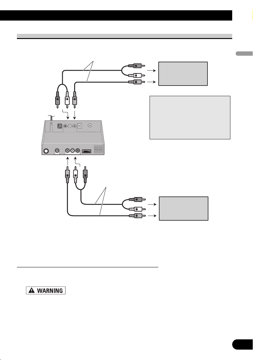
When connecting the external video component and the display
• It is necessary to set to “AV INPUT” or “REAR DISP” in “SETUP” when connecting
the external video component.
When using a display connected to rear video output
This product’s rear video output is for connection of a display to enable passengers in the
rear seats to watch the video source.
• NEVER install the rear display in a location that enables the driver to watch the video source while
Driving.
• NEVER connect rear audio output (REAR OUT) to separately sold power amp.
16
English
Español
Deutsch
Français
Italiano
Nederlands
Note:
The map screen navigation images
output to the rear display differ from
standard NTSC format images.
Therefore, their quality will be inferior to the images that appear on the
front display.
RCA cables
(sold separately)
To audio inputs
Display with
RCA input jacks
To video input
Hide-away unit
RCA cables
(sold separately)
To audio outputs
To video output
External video
component
(sold separately)
Page 18

17
Installation
• Pioneer does not recommend that you install or service your navigation system yourself. Installing or servicing the product may expose you to risk of
electric shock or other hazards. Refer all installation and servicing of your
navigation system to authorised Pioneer service personnel.
• Never install this product in places, or in a manner that where:
* It could injure the driver or passengers if the vehicle stops suddenly.
* It may interfere with the driver’s operation of the vehicle, such as on the
floor in front of the driver’s seat, or close to the steering wheel or gearstick.
• Make sure there is nothing behind the dashboard or panelling when drilling
holes in them. Be careful not to damage fuel lines, brake lines, electronic
components, communication wires or power cables.
• When using screws, do not allow them to come into contact with any electrical lead. Vibration may damage wires or insulation, leading to a short circuit
or other damage to the vehicle.
• To ensure proper installation, use the supplied parts in the manner specified.
If any parts other than the supplied ones are used, they may damage internal
parts of this product or they may work loose and the product may become
detached.
• It is extremely dangerous to allow the GPS aerial lead or microphone lead to
become wound around the steering column or gearstick. Be sure to install
this product in such a way that it will not obstruct driving.
• Make sure that leads cannot get caught in a door or the sliding mechanism of
a seat, resulting in a short circuit.
• Please confirm the proper function of your vehicle’s other equipment following installation of the navigation system.
• Certain government laws may prohibit or restrict the placement and use of
this system in your vehicle. Please comply with all applicable laws and regulations regarding the use, installation and operation of your navigation system.
Page 19

• Do not install this product where it may (i) obstruct the driver’s vision, (ii)
impair the performance of any of the vehicle’s operating systems or safety
features, including airbags, hazard lamp buttons or (iii) impair the driver’s
ability to safely operate the vehicle.
• Install the display unit between the driver’s seat and front passenger seat so
that it will not be hit by the driver or passenger if the vehicle stops quickly.
• Never install the display unit in front of or next to the place in the dash,
door, or pillar from which one of your vehicle’s airbags would deploy. Please
refer to your vehicle’s Owner’s Manual for reference to the deployment area
of the frontal airbags.
• Do not install this product in a place where it will impair the performance of
any of the vehicle’s operating systems, including airbags and headrests.
To guard against electromagnetic interference
• In order to prevent interference, set the following items as far as possible from the dis-
play unit and Hide-away unit of this navigation system, other cables or leads:
- TV aerial and aerial lead
- FM, MW/LW aerial and its lead
- GPS aerial and its lead
In addition you should lay or route each aerial lead as far as possible from other aerial
leads.
Do not bind them together, lay or route them together, or cross them.
Such electromagnetic noise will increase the potential for errors in the location display.
Before installing
• Consult with your nearest dealer if installation requires the drilling of holes or other mod-
ifications of the vehicle.
• Before making a final installation of this product, temporarily connect the wiring to con-
firm that the connections are correct and the system works properly.
18
English
Español
Deutsch
Français
Italiano
Nederlands
Page 20
19
Installation
Installing this product
Installation notes
• Do not install this product in places where it may become subject to high temperatures
or humidity, such as:
* Places close to a heater, vent or air conditioner.
* Places exposed to direct sunlight, such as on top of the dashboard or the rear shelf.
* Places that may be splashed by rain, for example close to the door.
• Install this product in an area strong enough to bear its weight. Choose positions where
this product can be firmly installed, and install it securely.
If the display unit or Hide-away unit are not securely installed, the current location of
the vehicle cannot be displayed correctly.
• When installing this product, make sure none of the leads are trapped between the unit
and the surrounding metalwork or fittings.
• Do not install the Hide-away unit and the Bluetooth adapter on the board covering the
spare tyre or other places which are subject to vibration.
• When the Hide-away unit and the Bluetooth adapter are installed under a front seat,
ensure that they do not obstruct the sliding action of the seat.
• When installing the Hide-away unit, choose a position that ensures there will be no contact with luggage. The impact of a heavy weight or sudden shock on the Hide-away unit
will adversely affect the accurate display of the current location of the vehicle.
• Avoid installing the Hide-away unit and the Bluetooth adapter in places where they will
interfere with loading and unloading of the spare tyre, jack, tools, etc.
• When installing a Bluetooth adapter, be sure to make sufficient space on its top surface.
There is an aerial under the top surface and covering it may cause trouble to the radio
transmission and reception.
• Depending on the location of a Bluetooth adapter, some noise could be heard during a
voice call. In this situation, move the Bluetooth adapter so as to reduce noise.
• Check that a disc can be ejected with the display unit installed.
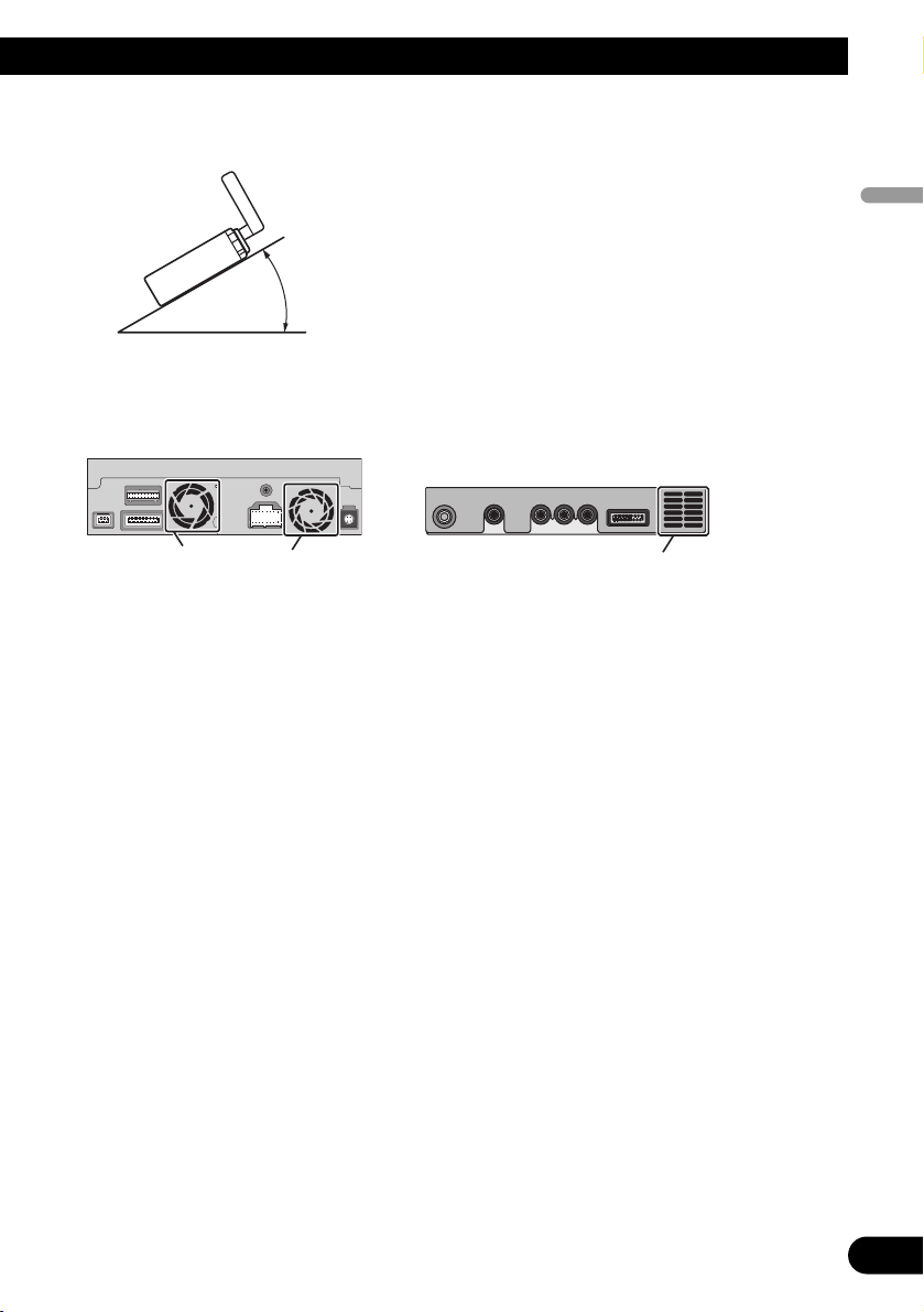
• Install the Hide-away unit horizontally on a surface within +30 degrees to –30 degrees
tolerance (within five degrees to the left or right of your vehicle’s direction of travel).
Mis-installing the unit with the surface tilted more than these tolerances would increase
the potential for errors in the location display, and might otherwise cause reduced display performance.
5°
30°
30°
Page 21
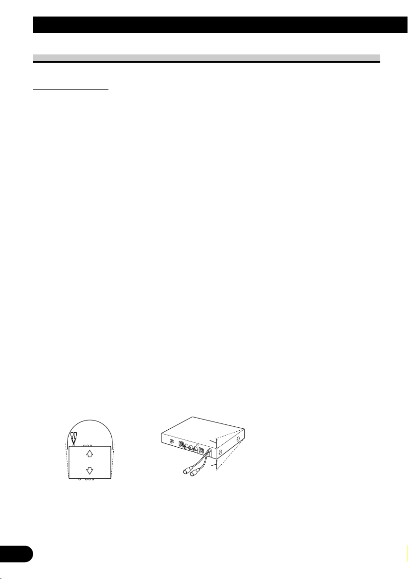
• If installation angle exceeds 30º from horizontal, the display unit might not give its optimum performance.
• The cords must not cover up the area shown in the figure below. This is necessary to
allow the amplifiers and navigation mechanism to heat dissipate freely.
• The semiconductor laser will be damaged if it overheats, so don’t install the product
anywhere hot — for instance, near a heater outlet.
• When installing the Hide-away unit in the boot, use the extension cable (e.g. CDSC300E) (sold separately).
• Do not install the display unit in a position where the opening of the LCD panel is
obstructed by any obstacles, such as the gearstick. This may cause interference with the
gearstick, or a malfunction of the mechanism of the display unit.
• Install the microphone in a position and orientation that will enable it to pick up well the
voice of the person operating the system by voice.
20
English
Español
Deutsch
Français
Italiano
Nederlands
30°
Display unit
Do not cover these areas.
Hide-away unit
Do not cover this area.
Page 22
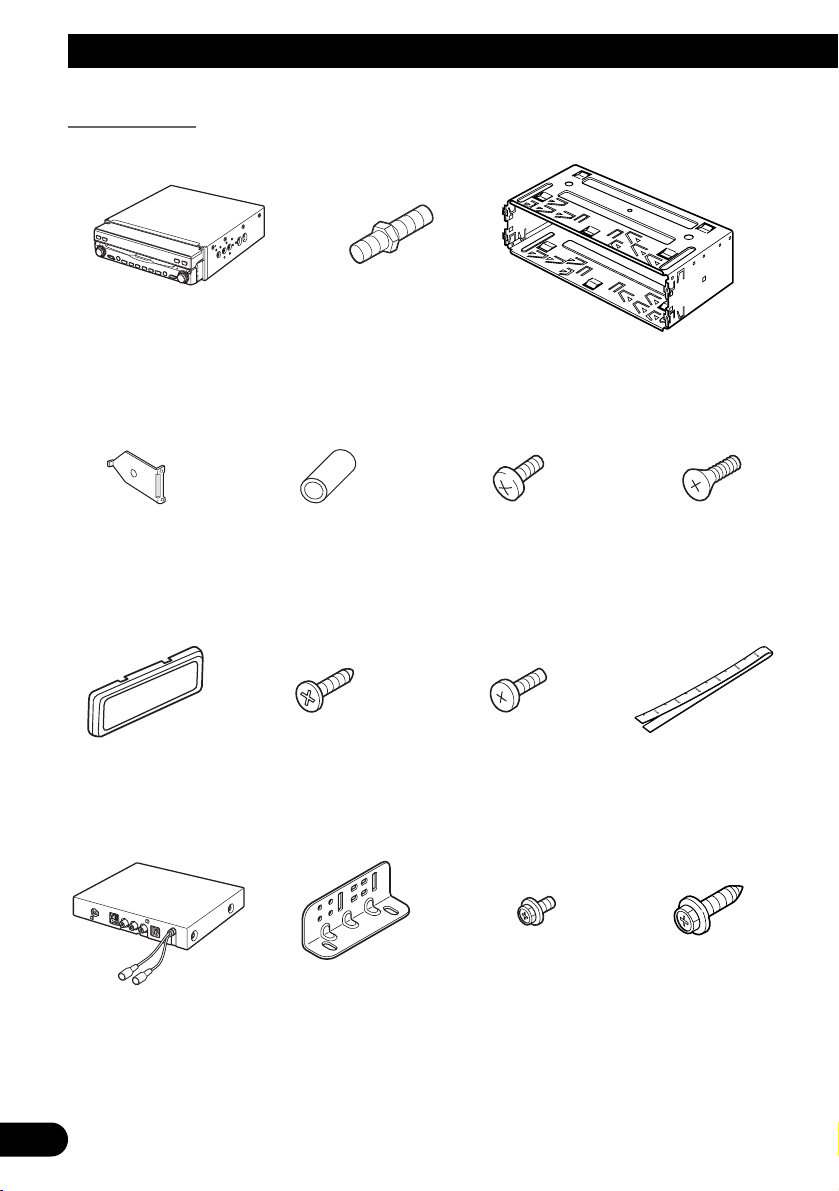
Parts supplied
21
Installation
Holder
Side bracket
(2 pcs.)
Screw
Display unit
Rubber bush
Binding screw
(5 × 6 mm)
(4 pcs.)
Flush surface screw
(5 × 6 mm)
(4 pcs.)
Frame Screw
(4 × 3 mm)
(4 pcs.)
Fixing screw
(2 pcs.)
Conceal tape
Hide-away unit
Side bracket
(2 pcs.)
Washer faced screw
(4 × 8 mm)
(4 pcs.)
Self-tapping screw
(6 × 16 mm)
(4 pcs.)
Page 23
Clamp
(5 pcs.)
Double-sided tape
(small)
Microphone clipMicrophone
Velcro tape (soft) (2 pcs.)Velcro tape (hard) (2 pcs.)Bluetooth adapter
22
English
Español
Deutsch
Français
Italiano
Nederlands
Page 24
23
Installation
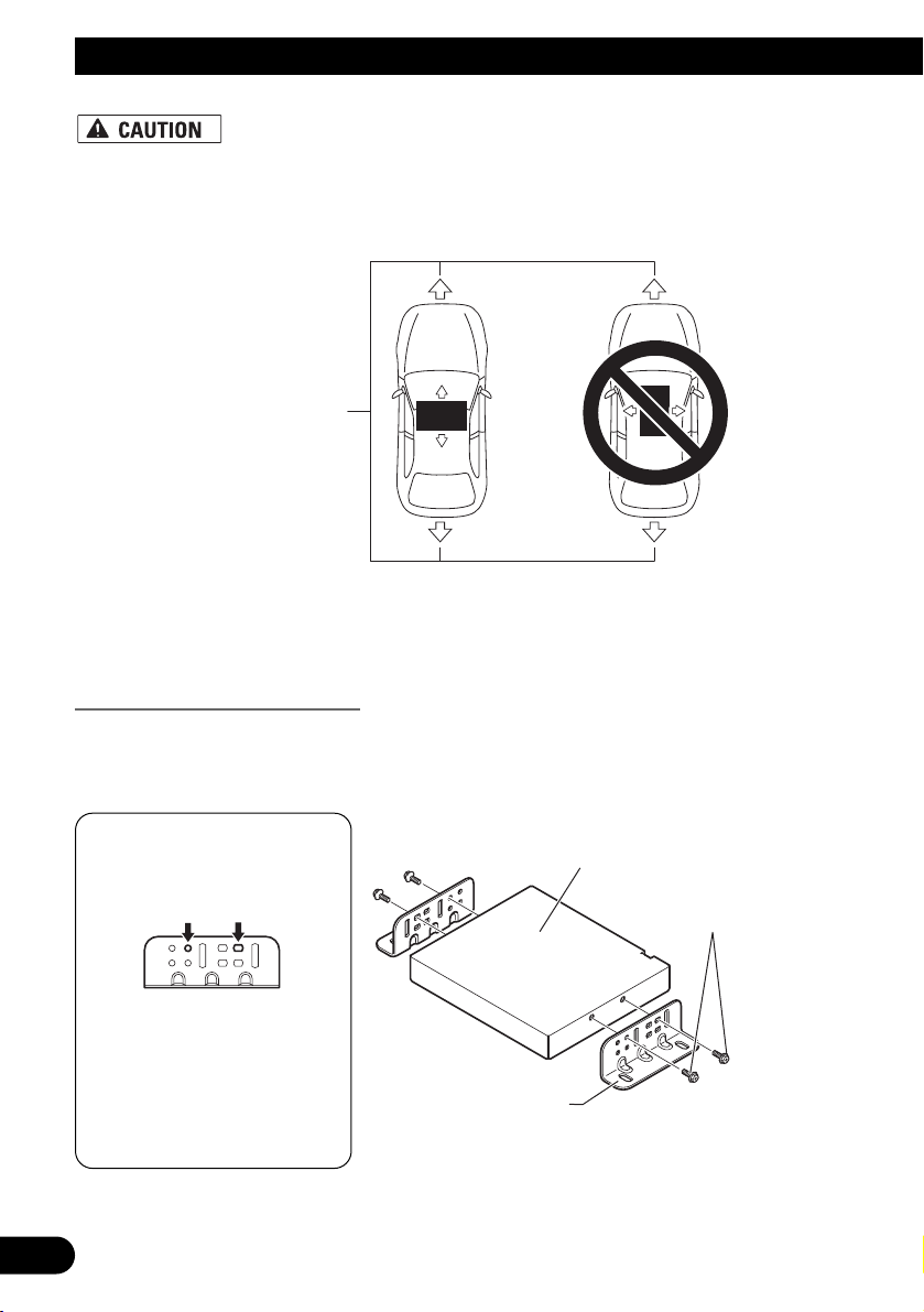
• Install with the left and right sides of the Hide-away unit perpendicular or parallel to your vehicle’s direction of travel. Do not install diagonally to your vehicle’s direction of travel or the current location will be displayed incorrectly.
• Be sure to install the Hide-away unit on the floor with the silk printing side is
facing up. The navigation system will operate properly only in this position.
Installing the Hide-away unit
1. Attach the side brackets to the Hide-away unit.
When the Hide-away unit is installed on the floor or the installation board under the passenger seat, etc., the side brackets should be attached to the unit.
If the positions of the side
plates are shifted in parallel you can also use other
holes that match up with
the holes in the Hideaway unit.
Use the following holes in
the side brackets.
Forward/Backward
direction of vehicle
Hide-away unit
Washer faced screw
(4 × 8 mm)
Side bracket
Page 25
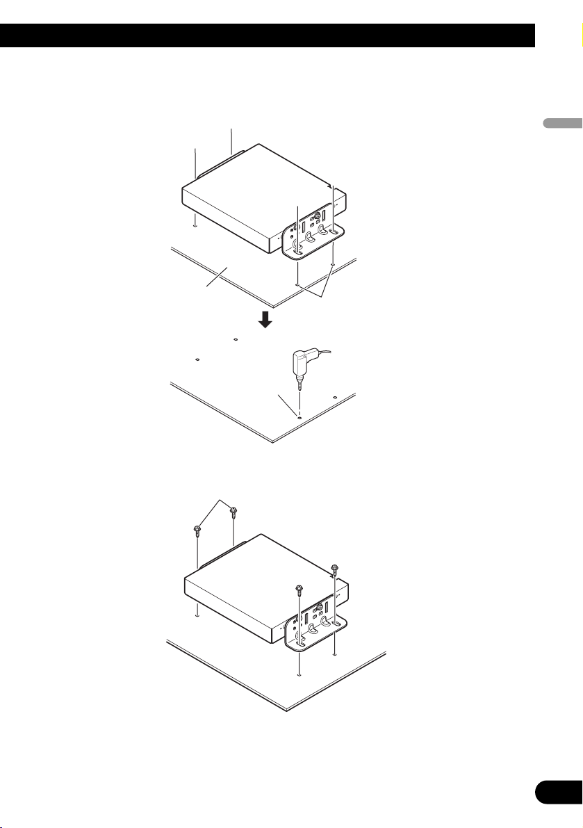
When the Hide-away unit is installed under the passenger seat, etc., use the installation
board.
2. Decide on the installation position, and drill the holes.
3. Secure it firmly using the self-tapping screws.
24
English
Español
Deutsch
Français
Italiano
Nederlands
Installation board
Mark up the positions
for drilling the holes.
Drill holes of between 4
and 4.5 mm in diameter.
Self-tapping screw
(6 × 16 mm)
Page 26
25
Installation
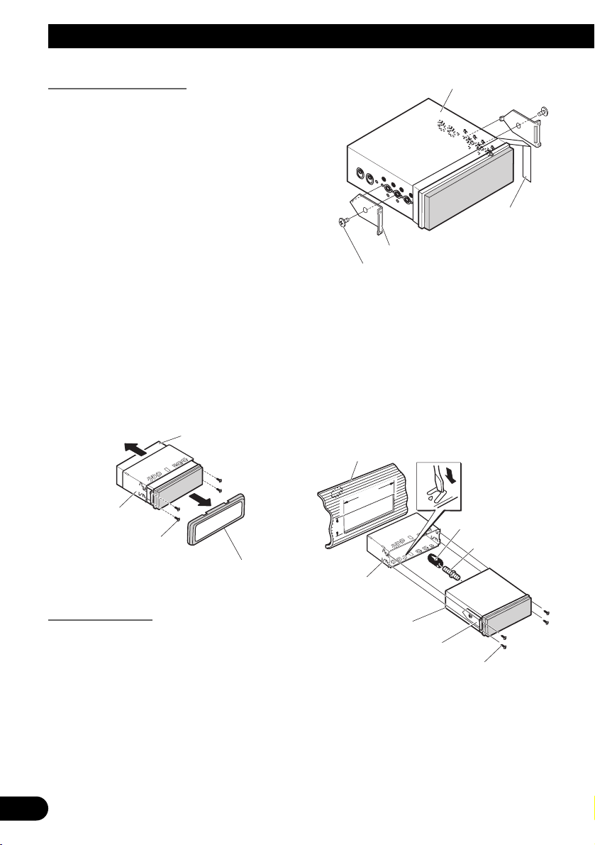
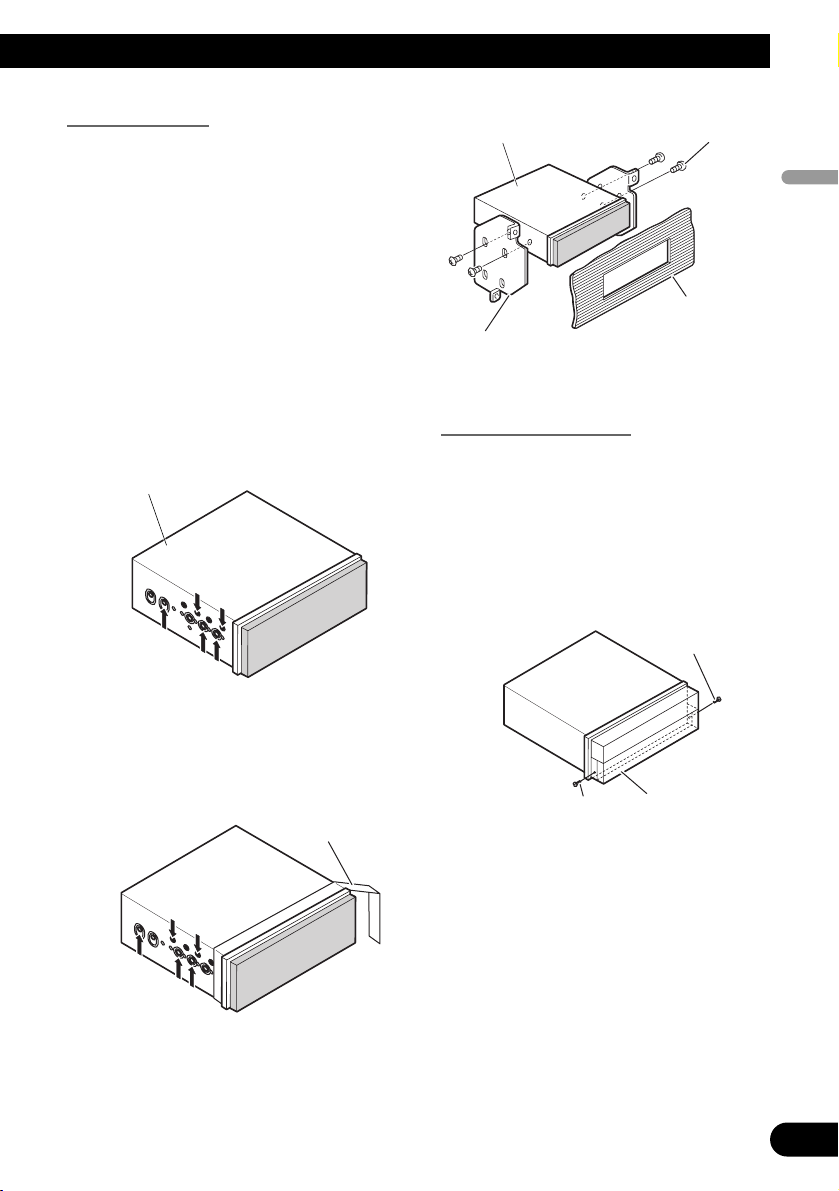
DIN Front/Rear-mount
The display unit can be properly
installed either from “Front” (conventional DIN Front-mount) or “Rear”
(DIN Rear-mount installation, using
threaded screw holes at the sides of the
unit chassis). For details, refer to the
following illustrated installation methods.
Before installing the display unit
• Remove the frame and the
holder.
To remove the frame, extend top and
bottom of the frame outwards in order
to unlock it.
Loosen the screws (2 × 3 mm) to
remove the holder. (When reattaching
the frame, point the side with a groove
downwards and attach it.)
• It becomes easy to remove the frame
if the front panel is released.
DIN Front-mount
Installation with the rubber bush
1. Decide the position of the side
brackets.
When installing in a shallow space,
change the position of side brackets. In
this case, stick conceal tape on parts
that protrude from the dashboard.
2. Install the display unit into the
dashboard.
After inserting the holder into the
dashboard, select the appropriate tabs
according to the thickness of the dashboard material and bend them.
(Install as firmly as possible using the
top and bottom tabs. To secure, bend
the tabs 90 degrees.)
• After installing the display unit into
the dashboard, reattach the frame.
• If you prefer an off-set installation
in which the front panel is pushed
further back, when there is a space
available at the back of the unit, use
AD-GA10 (sold separately).
Display unit
Display unit
Conceal tape
Side bracket
Flush surface screw (5 × 6 mm)
Dashboard
Holder
Screw (2 × 3 mm)
Frame
182
53
Holder
Display unit
Side bracket
Screw (2 × 3 mm)
Rubber bush
Scre
w
Page 27
DIN Rear-mount
Installation using the screw holes on the
side of the display unit
• Fastening the display unit to the
factory radio-mounting bracket.
Select a position where the screw holes
of the bracket and the screw holes of
the display unit become aligned (are
fitted), and tighten the screws at 2
places on each side. Use any of screws
(4 × 3 mm), binding screws (5 × 6
mm) or flush surface screws (5 × 6
mm), depending on the shape of the
screw holes in the bracket.
*1 Use screws (4 × 3 mm) only.
• When installing in a shallow space,
use the following screw holes. In
this case, stick conceal tape on parts
that protrude from the dashboard.
Fixing the front panel
If you do not operate the removing and
attaching the front panel function, use
the supplied fixing screws to fix the
front panel to the display unit.
• Fix the front panel to the display
unit using the fixing screws after
removing the frame.
*
1
*
1
Display unit
26
English
Español
Deutsch
Français
Italiano
Nederlands
Display unit
Factory radio mounting
bracket
Binding screw
(5 × 6mm)
Dashboard or
Console
Conceal tape
1
*
1
*
Fixing screw
Fixing screw
Front panel
Page 28
27
Installation
Installing the Bluetooth adapter
Adhere the hard Velcro tape (provided) to the bottom of the Bluetooth adapter and adhere
the soft Velcro tape (provided) to the installation location.
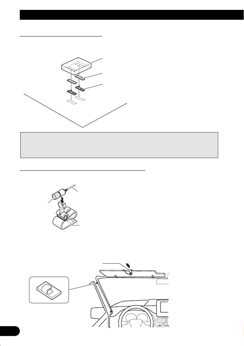
When installing the microphone on the sun visor
1. Install the microphone on the microphone clip.
2. Install the microphone clip on the sun visor.
With the sun visor up, install the microphone clip. (Lowering the sun visor reduces the
recognition rate for voice operations.)
Notes:
• Direct installation on the carpet is possible if the hard Velcro tape will adhere to the
carpet. Do not use the soft Velcro tape in this case.
• Thoroughly wipe off the surface before affixing the velcro tape.
Bluetooth adapter
Velcro tape (hard)
Velcro tape (soft)
Vehicle mat or chassis
to Bluetooth adapter
Microphone
Microphone clip
Microphone clip
Clamps
Use clamps to secure the
lead where necessary inside
the vehicle.
Page 29
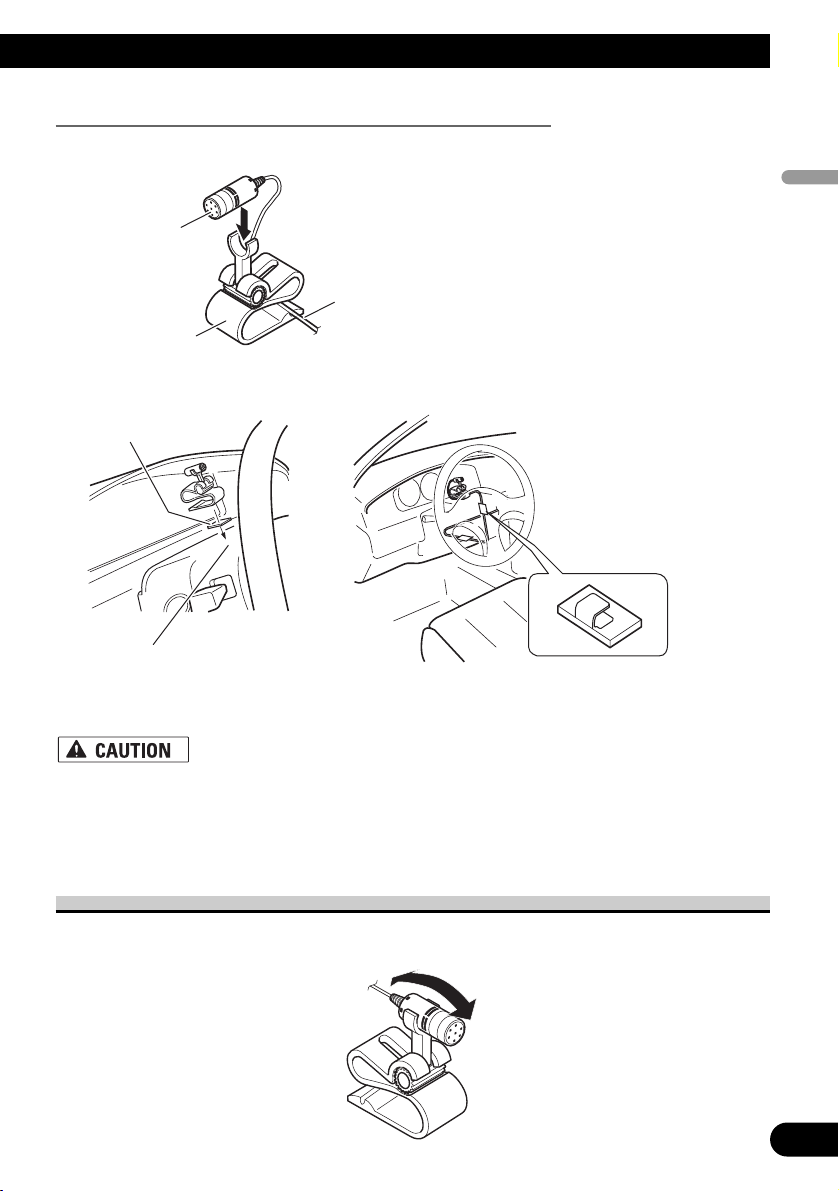
When installing the microphone on the steering column
1. Install the microphone on the microphone clip.
2. Install the microphone clip on the steering column.
• It is extremely dangerous to allow the microphone lead to become wound
around the steering column or gearstick. Be sure to install the unit in such a
way that it will not obstruct driving.
Adjusting the microphone angle
The microphone angle can be adjusted by moving forward or backward the microphone
clip angle.
d
28
English
Español
Deutsch
Français
Italiano
Nederlands
Microphone
Fit the microphone lea
the groove.
Microphone clip
Double-sided tape
into
Clamps
Use clamps to secure the
lead where necessary
inside the vehicle.
Install the microphone clip on
the rear side of the steering
column.
Page 30
29
Installation
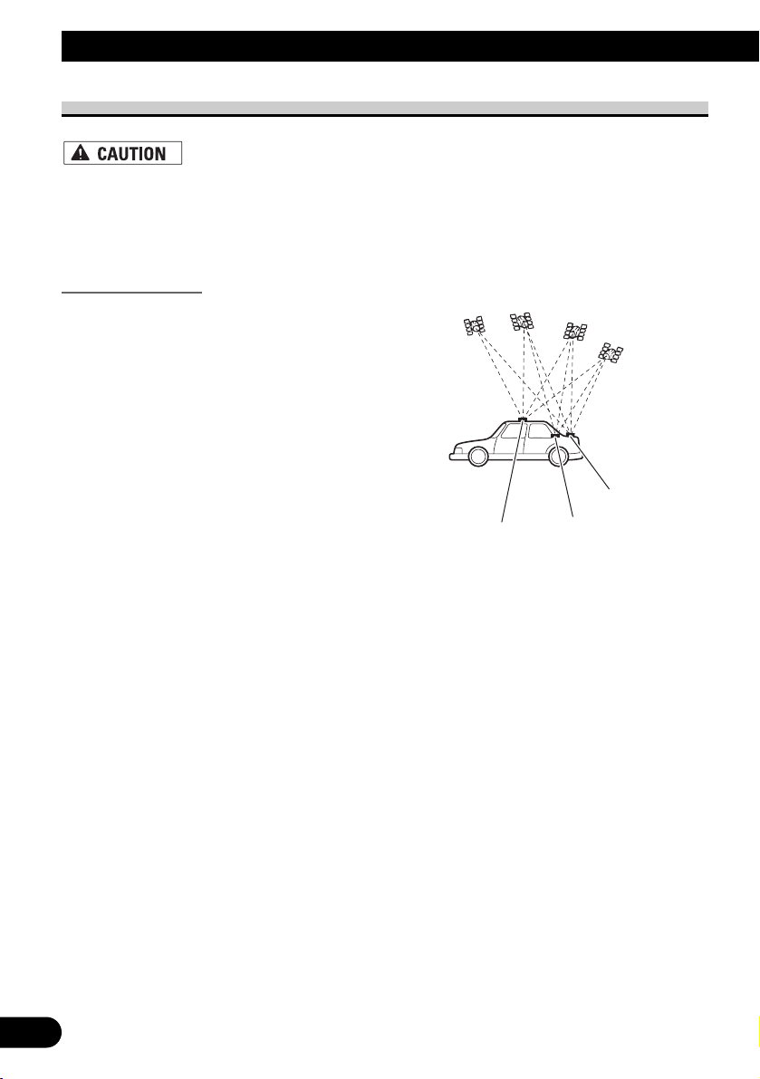
Installing the GPS aerial
• Do not cut the GPS aerial lead to shorten it or use an extension to make it
longer. Altering the aerial cable could result in a short circuit or malfunction
and permanent damage to the product.
Installation notes
• When installing the GPS aerial inside the vehicle, be sure to use the metal sheet
provided with your system. If this is not used, the reception sensitivity will be poor.
• Do not cut the accessory metal sheet. This would reduce the sensitivity of the GPS
aerial.
• Take care not to pull the aerial lead when removing the GPS aerial. The magnet attached
to the aerial is very powerful, and the lead may become detached.
• The GPS aerial is installed with a magnet. When installing the GPS aerial, be careful
not to scratch the vehicle body.
• When installing the GPS aerial on the outside of the vehicle, always put it in the vehicle
when going through an automatic vehicle wash. If it is left on the outside it may be
knocked off and scratch the vehicle body.
• Do not paint the GPS aerial, as this may affect its performance.
• The aerial should be installed on a
level surface where radio waves will
be blocked as little as possible. Radio
waves cannot be received by the aerial
if reception from the satellite is
blocked.
Installation on the vehicle roof or boot
lid is recommended to optimise reception.
Boot lid
Roof
Rear shelf
Page 31

Parts supplied
When installing the aerial inside the vehicle (on the rear shelf)
Affix the metal sheet on as level a surface as possible where the GPS aerial faces the window. Place the GPS aerial on the metal sheet. (The GPS aerial is fastened with its magnet.)
Notes:
• When attaching the metal sheet, do not cut it into small pieces.
• Some models use window glass that does not allow signals from GPS satellites to pass
through. On such models, install the GPS aerial on the outside of the vehicle.
Waterproof padClamp (5 pcs.)Metal sheetGPS aerial
30
English
Español
Deutsch
Français
Italiano
Nederlands
GPS aerial
Metal Sheet
Peel off the protective sheet
on the rear.
Make sure the surface is
free of moisture, dust,
grime, oil, etc., before
affixing the metal sheet.
Note: The metal sheet
contains a strong adhesive
which may leave a mark on
the surface if it is removed.
Clamps
Use clamps to secure the
lead where necessary inside
the vehicle.
Page 32

31
Installation
When installing the aerial outside the vehicle (on the body)
Put the GPS aerial in a position as level as possible, such as on the roof or boot lid. (The
GPS aerial is fastened with a magnet.)
Clamps
Use clamps to secure
the lead where
necessary inside the
vehicle.
Clamps
Use clamps to secure the
lead where necessary inside
the vehicle.
GPS aerial
When routing the lead in from the top of the
door
Make a U-shaped loop in the lead
on the outside to prevent rainwater
from flowing along the lead into the
interior of the vehicle.
When routing the lead in from inside the boot
Waterproof pad
Make sure the waterproof pad
contacts the top of the rubber
packing.
Make a U-shaped loop in the
lead outside the rubber
packing to prevent rainwater
from flowing along the lead
into the interior of the vehicle.
Rubber packing
Page 33

After Installing this Product
1. Reconnecting the battery.
First, double-check that all connections are correct and that this product is installed correctly. Reassemble all vehicle components that you previously removed. Then reconnect
the negative (–) cable to the negative (–) terminal of the battery.
2. Start the engine.
3. Press the RESET button.
• Press the RESET button on the display unit using a pointed object such as the tip of a
pen.
• Press the RESET button on the Bluetooth adapter using a pointed object such as the tip
of a pen.
4. Enter the following settings:
1. Install the programme in the navigation system.
2. Drive until the initialised sensors start operating normally.
3. Set the time and language.
Set the navigation system as explained in the Operation Manual or Hardware Manual.
After installing this product, be sure to check at a safe place that the vehicle is performing normally.
Note:
If you reconnected the Hide-away unit, press the RESET button.
32
English
Español
Deutsch
Français
Italiano
Nederlands
Page 34

1
INFORMACIÓN IMPORTANTE
ACERCA DE SU NUEVO SISTEMA DE NAVEGACIÓN Y ESTE MANUAL
• Las funciones de navegación de este producto (y de la opción de cámara de visión
trasera si se ha adquirido) están pensadas únicamente para ayudarle en el manejo
de su vehículo. De ninguna forma debe considerarse como un acaparador de su
atención, buen juicio y cuidado durante la conducción.
• Nunca utilice este sistema de navegación para guiarse hasta hospitales, comisarías
de policía o instalaciones parecidas si se produce una emergencia. En tal caso,
llame al número de emergencias correspondiente.
• No active el sistema de navegación (o la opción de cámara de visión trasera si se
ha adquirido) si al hacerlo deja de prestar atención y pone en peligro el manejo
seguro de su vehículo. Las limitaciones y consejos sobre el tráfico existentes en
cada momento deben tomarse siempre con prioridad respecto a la guía que proporciona este producto. Haga caso siempre de las limitaciones de tráfico existentes en cada momento, aunque este producto aconseje lo contrario.
• Este manual explica cómo instalar este sistema de navegación en su automóvil. El
funcionamiento de este sistema de navegación se explica en el Manual de instrucciones o Manual de hardware independiente del sistema de navegación.
• No instale este producto en puntos en los que pueda (i) dificultar la visión del
conductor, (ii) comprometer el funcionamiento de alguno de los sistemas de
seguridad del vehículo, como los airbags, los botones de los indicadores de peligro, o (iii) comprometer la capacidad del conductor para manejar el vehículo con
seguridad. En algunos casos, es posible que este producto no pueda instalarse
debido al tipo de vehículo o a la forma del interior del vehículo.
Page 35

English
Español
Deutsch
Français
Italiano
Nederlands
INFORMACIÓN IMPORTANTE ................ 1
ACERCA DE SU NUEVO SISTEMA DE
NAVEGACIÓN Y ESTE MANUAL ........ 1
PRECAUCIONES IMPORTANTES ............ 3
LEA TODAS ESTAS INSTRUCCIONES
RELACIONADAS CON SU SISTEMA DE
NAVEGACIÓN Y GUÁRDELAS PARA
EMPLEARLAS COMO REFERENCIA EN
EL FUTURO .............................................. 3
Conexión del sistema ................................ 4
-
Antes de instalar este producto
-
Para impedir daños
-
Partes suministradas
Conexión del sistema ........................................ 7
Conexión del cable de alimentación (1) ............ 9
Conexión del cable de alimentación (2) .......... 11
Conexión al amplificador de potencia que se
vende por separado.................................... 13
Conexión de una cámara para visión trasera .. 15
Conexión del vídeo externo y la pantalla ........ 16
-
Uso de una pantalla conectada a la salida
trasera de vídeo
Instalación ................................................ 17
Para impedir que se produzcan interferencias
electromagnéticas .................................... 18
Antes de la instalación .................................... 18
Instalación de este producto ............................ 19
-
Notas acerca de la instalación
-
Partes suministradas
-
Instalación de la unidad oculta-alejada
-
Montaje trasero/delantero DIN
-
Montaje delantero DIN
-
Montaje trasero DIN
-
Fijación del panel delantero
-
Instalación del adaptador Bluetooth
-
Cuando instale el micrófono en el parasol
-
Cuando instale el micrófono en la base del
volante
Ajuste del ángulo del micrófono .................... 28
Instalación de la antena GPS .......................... 29
-
Notas acerca de la instalación
-
Partes suministradas
-
Cuando instale la antena en el interior del
vehículo (en el estante trasero)
-
Cuando instale la antena en el exterior del
vehículo (en la carrocería)
Después de instalar este producto........ 32
2
Contenido
Page 36

PRECAUCIONES IMPORTANTES
3
LEA TODAS ESTAS INSTRUCCIONES RELACIONADAS CON SU SISTEMA
DE NAVEGACIÓN Y GUÁRDELAS PARA EMPLEARLAS COMO REFERENCIA
EN EL FUTURO
1. Lea completa y detenidamente este manual antes de instalar su sistema de navegación.
2. Guarde al alcance de la mano este manual para utilizarlo como referencia en el
futuro.
3. Ponga mucha atención a todas las advertencias de este manual y siga cuidadosamente las instrucciones.
4. En ciertas circunstancias, este sistema de navegación puede mostrar una información errónea de la posición de su vehículo, la distancia de los objetos mostrados
en la pantalla y las direcciones de la brújula. Además, el sistema tiene ciertas limitaciones, incluyendo la incapacidad de identificar calles de una dirección, restricciones temporales de tráfico y zonas donde la conducción pueda resultar peligrosa. Haga uso de su buen juicio en función de las condiciones de conducción
reales.
5. Al igual que con cualquier otro accesorio del interior, el sistema de navegación
nunca deberá distraerle ni poner en peligro el manejo seguro de su vehículo. Si
encuentra dificultades al utilizar el sistema o al leer la visualización, haga los
ajustes necesarios con el vehículo estacionado en un lugar seguro.
6. Recuerde ponerse siempre el cinturón de seguridad cuando maneje su automóvil.
En el caso de sufrir un accidente, sus lesiones pueden ser mucho más graves si no
tiene bien puesto su cinturón de seguridad.
7. Las leyes de ciertos países pueden limitar la ubicación y el uso de sistemas de
navegación en el vehículo. Cumpla con todas las leyes y normas pertinentes en
cuanto a la instalación y el funcionamiento de su sistema de navegación.
No intente instalar o revisar usted mismo el sistema de navegación.
La instalación o revisión del sistema de navegación por personas sin formación o
experiencia en equipos electrónicos y accesorios para automóviles puede ser peligrosa y podría exponerle a una descarga eléctrica o a otros peligros.
Page 37

English
Español
Deutsch
Français
Italiano
Nederlands
4
Conexión del sistema
• Pioneer aconseja que no realice usted mismo la instalación del sistema de navegación. Recomendamos que sólo el personal de servicio autorizado de Pioneer, que
cuenta con formación especializada y experiencia en el campo de la electrónica
móvil, instale y configure este producto. NUNCA EFECTÚE EL MANTENIMIENTO DE ESTE PRODUCTO USTED MISMO. La instalación o el mantenimiento
del producto y de los cables de conexión asociados puede exponerle al riesgo de una
descarga eléctrica u otros peligros, y puede ocasionar daños en el sistema de navegación que no cubre la garantía.
• Si decide efectuar la instalación usted mismo y cuenta con formación especializada
y experiencia en la instalación de sistemas electrónicos móviles, siga con cuidado
todos los pasos descritos en el Manual de instalación.
• Asegure todo el cableado con abrazaderas de cables o cinta para usos eléctricos. No
permita que el cableado pelado permanezca descubierto.
• No enchufe directamente el cable amarillo de este producto a la batería del vehículo. Si lo hace, puede que la vibración del motor acabe provocando un problema
relacionado con el aislamiento en el punto por donde el cable cruza del compartimiento del pasajero al compartimiento del motor. Si se rompe el aislamiento del
cable amarillo como resultado del contacto con partes metálicas, puede producirse
un cortocircuito y generar por tanto un peligro considerable.
• Es peligrosísimo dejar que el cable de la antena GPS y el cable del micrófono se
enrollen en la base del volante o en la palanca de cambios. Asegúrese de instalar
este producto, los cables de la unidad y el cableado a cierta distancia de forma que
no dificulten o impidan la conducción.
• Asegúrese de que todos los cables estén enrutados y sujetos de manera que no
entorpezcan o queden atrapados con alguna de las partes móviles del vehículo, en
especial con el volante, la palanca de cambio, el freno de mano, las guías de los
asientos deslizantes, las puertas o con alguno de los controles del vehículo.
• No enrute cables que vayan a estar sometidos a altas temperaturas. Si se calienta el
aislamiento, los cables pueden resultar dañados y, como consecuencia, puede producirse un cortocircuito o una avería y el producto puede sufrir un deterioro permanente.
• No corte el cable de la antena GPS para reducir su longitud ni utilice una extensión
para alargarlo. La alteración del cable de la antena puede causar un cortocircuito.
• No acorte ningún cable. En el caso de que lo haga, el circuito de protección (el
portafusibles, la resistencia de fusible o el filtro, etc.) puede que no funcione
correctamente.
• Nunca suministre alimentación a otros productos electrónicos cortando el aislamiento del cable de alimentación del sistema de navegación y tomando corriente
de él. La capacidad nominal del cable se excederá y causará un recalentamiento.
• El cable posterior es de conexión a tierra. Conecte este cable a una toma de tierra
distinta de productos de alta corriente, como, por ejemplo, amplificadores de
potencia. No conecte a tierra más de un componente junto con la tierra de otro
componente. Por ejemplo, debe conectar a tierra por separado cualquier unidad de
amplificador y la tierra de la unidad oculta-alejada. La conexión conjunta de la
tierra de uno y otro puede ocasionar un incendio y/o dañar los productos si se
desprende la tierra de cada uno.
Page 38

5
Conexión del sistema
Antes de instalar este producto
• Este producto es para vehículos con batería de 12 voltios y con conexión a tierra.
Compruebe el voltaje de la batería de su vehículo antes de proceder a la instalación.
Para impedir daños
• Cuando desconecte un conector, tire del propio conector. No tire del cable porque podría
sacarlo del conector.
• Este producto no puede instalarse en un vehículo que no disponga de la posición ACC
(accesorio) en el interruptor de encendido.
• Para evitar cortocircuitos, cubra el conductor desconectado con cinta aislada. Es especialmente importante aislar todos los cables de altavoz que no se usen, ya que si no se recubren
pueden llegar a provocar un cortocircuito.
• Acople los conectores de un color determinado al puerto correspondiente del mismo color,
es decir, el conector azul al puerto azul, el conector negro al puerto negro, etc.
• Consulte el manual del propietario para obtener información sobre la conexión del amplificador de potencia y de otras unidades y, a continuación, realice las conexiones de manera
acorde.
• Al sustituir el fusible, asegúrese de utilizar exclusivamente un fusible del régimen nominal
descrito en el portafusible.
• Como se utiliza un circuito BPTL único, no conecte directamente a tierra el lado ≠ del
cable del altavoz ni conecte juntos los lados ≠ de los cables de los altavoces. Asegúrese de
conectar el lado ≠ del cable del altavoz al lado ≠ del cable del altavoz en la unidad de
pantalla.
• Si no se utiliza el enchufe de clavijas RCA de este producto, no extraiga las tapas sujetas al
extremo del conector.
• Nunca conecte altavoces con un valor de salida inferior a 50 W por canal o una impedancia
distinta de los 4 ohmios a 8 ohmios especificados para su sistema de navegación. Si se
efectúa la conexión de altavoces con unos valores de salida y/o de impedancia distintos a
los especificados puede derivar en que los altavoces se incendien, desprendan humo o
resulten dañados.
• Cuando se utiliza la función de antena automática conectando el cable azul al
vehículo con la función de antena automática, se retrae la antena automática del
vehículo en el caso de apagar el interruptor de encendido o de desmontar el panel
delantero.
Sin posición ACC Posición ACC
• Para evitar cortocircuitos en el sistema
eléctrico, asegúrese de desconectar el
cable de la batería (–) antes de comenzar con la instalación.
C
C
A
O
F
N
F
O
S
T
A
R
T
O
F
N
F
O
S
T
A
R
T
Page 39

English
Español
Deutsch
Français
Italiano
Nederlands
6
• Al conectar el interruptor de encendido (ACC ON), se envía una señal de control por el
cable azul/blanco. Conéctelo al terminal de control remoto del sistema externo de amplificadores de potencia (máx. 300 mA 12 V CC). La señal de control se envía por el cable
azul/blanco, aunque se haya quitado el panel frontal o la fuente de audio esté desconectada.
• Cuando se emplea un amplificador de potencia externo con este sistema, asegúrese de no
conectar el cable azul al terminal de alimentación del amplificador. De la misma manera,
no conecte el cable azul al terminal de alimentación de la antena automática. Una conexión
de este tipo podría provocar una pérdida de corriente excesiva y un mal funcionamiento así
como daños en la antena automática del vehículo.
Partes suministradas
Cable IP-BUSCable de alimentaciónMicrófono
Adaptador BluetoothPresilla de sujeción Conector de extensión
del sistema
Cable de antena de extensión Antena GPS Cable de extensión
(para la señal de velocidad)
Cable de extensión
(para la señal de marcha atrás)
Cable de 30 patillas Conector
Cable de alimentaciónUnidad oculta-alejada Unidad de pantalla
Page 40

7
Conexión del sistema
Conexión del sistema
3 m
5 m
Cable IP-BUS (suministrado con adaptador iPod)
*:
Adaptador
Bluetooth
(CD-BT10)
Micrófono*
(suministrado)
Reproductor de
Multi-CD (se vende
por separado)
Amarillo
Unidad oculta-alejada
Azul
Azul
Azul
Cable AV-BUS
(suministrado con
el sintonizador TV)
Cable IP-BUS
(suministrado con el
sintonizador TV)
Cable IP-BUS
Antena GPS
Negro
Negro
Negro
Azul
Sintonizador TV ocultalejos
(p. ej. GEX-P5700TVP)
(se vende por separado)
Gris claro
Cable de antena
de extensión
(suministrado)
Al instalar la unidad
oculta-alejada en el
maletero, etc., es
necesario el cable
de extensión
(p. ej. CD-SC300E)
(se vende por
separado).
Para utilizar el sistema de navegación por voz, es
necesario el micrófono del kit de reconocimiento
de voz (p. ej. CD-VC1) (vendido por separado).
• Para evitar el riesgo de accidente y la
posible infracción de las leyes correspondientes, este producto no debe utilizarse nunca durante la conducción
del vehículo con otra finalidad distinta
a la navegación. También debe tenerse
en cuenta que las pantallas traseras no
deben situarse en un sitio que suponga
una distracción clara para el conductor.
• En algunos países o estados, la visualización de imágenes en una pantalla en
el interior de un vehículo incluso por
parte de los pasajeros puede ser ilegal.
Es preciso respetar dichas normas
donde estén en vigor y no deben utilizarse las funciones de fuente de vídeo
o TV de este producto.
Page 41

8
English
Español
Deutsch
Français
Italiano
Nederlands
Puerto
de conexión
Puerto de conexión (suministrado con adaptador iPod)
iPod con puerto
de conexión
Adaptador iPod
(p. ej. CD-IB100)
(vendido por separado)
3 m
3 m
20 cm
20 cm
Cable IP-BUS
(suministrado)
Amarillo
DIGITAL OUT*
Puerto de EXTENSIÓN
Sin uso.
Cable de 30 clavijas
Cable de
alimentación
Unidad de pantalla
G.SP (Salida del altavoz de guía)*
MIC INPUT
El micrófono del kit de
reconocimiento de voz (p. ej.
CD-VC1) (se vende por
separado) se conecta cuando se
utiliza la función de
reconocimiento de voz.
Negro
Azul
ENTRADA DEL CONTROL
REMOTO POR CABLE
Consulte el Manual de
instrucciones de los adaptadores
de control remoto por cable
(vendidos por separado).
*: Este terminal está pen-
sado para poder incorporar equipos en el
futuro y no debe usarse
si únicamente emplea
este producto sin más.
Page 42

9
Conexión del sistema
Conexión del cable de alimentación (1)
Adaptador
Bluetooth
(CD-BT10)
Fusible (2 A)
*1
*2
*4
*3
*5
Conecte los cables del
mismo color entre ellos.
Tapa (*1)
Cuando este terminal no esté
en uso, no extraiga la tapa.
Conector ISO
Fusible (10 A)
Amarillo (*2)
Al terminal, siempre dispone de
alimentación independientemente de
la posición del interruptor de encendido.
Rojo (*4)
Al terminal eléctrico que controla el
interruptor de encendido (12 V CC)
ON/OFF.
Amarillo (*3)
Reserva
(o accesorio)
Rojo (*5)
Accesorio
(o reserva)
Negro (tierra)
A la carrocería (metálica)
del vehículo.
Anaranjado/blanco
Al terminal del interruptor de
iluminación.
Resistencia de fusible
Resistencia de fusible
Según cual sea el tipo de vehículo, la
función de *3 y *5 puede variar. En tal
caso, asegúrese de conectar *2 a *5 y *4
a *3.
Cables de altavoz
Blanco: Izquierdo delantero +
Blanco/negro: Izquierdo delantero ≠
Gris: Derecho delantero +
Gris/negro: Derecho delantero ≠
Verde: Izquierdo trasero + o Altavoz de graves +
Verde/negro: Izquierdo trasero ≠ o Altavoz de graves ≠
Violeta: Derecho trasero + o Altavoz de graves +
Violeta/negro: Derecho trasero ≠ o Altavoz de graves ≠
Nota:
Nota:
En algunos vehículos, el conector ISO
puede estar dividido en dos. En tal
caso, asegúrese de conectar a los dos
conectores.
Amarillo
Al terminal, siempre dispone de
alimentación independientemente
de la posición del interruptor de
encendido.
Negro (tierra)
A la carrocería (metálica)
del vehículo.
Page 43

10
English
Español
Deutsch
Français
Italiano
Nederlands
GUIDE ON
SYSTEM REMOTE
CONTROL
Azul (*7)
Al terminal de control del relé de la antena
automática (máx. 300 mA 12 V CC).
Azul (*6)
Verde claro
Nota:
La fuente de audio se ajustará a silencio o
atenuación, mientras que la guía de voz del
sistema de navegación no quedará silenciada ni
atenuada. Para más información, consulte el
“Manual de instrucciones”.
Amarillo/negro
Si utiliza un equipo con una función de silencio
(p. ej. teléfonos móviles), conecte ese equipo al
cable de silencio de audio. Si no, deje ese cable
sin conexión.
Nota:
Cuando se utiliza la función de antena automática
conectando el cable azul al vehículo con la función de
antena automática, se retrae la antena automática del
vehículo en el caso de apagar el interruptor de encendido
o de desmontar el panel delantero.
Nota:
La posición de la clavija del conector ISO variará en
función del tipo de vehículo. Conecte *6 y *7
cuando la clavija 5 sea del tipo de control de antena.
En otros tipos de vehículo, nunca conecte *6 y *7.
Nota:
Los cables para este producto y los cables para
otros productos pueden ser de colores distintos
aunque tengan la misma función. Cuando conecte
este producto a otro producto, consulte los manuales proporcionados de ambos productos y
conecte los cables que tengan la misma función.
Unidad de pantalla
☞
Vea la página 12.
☞
Vea la página 11.
Page 44

Rosado (CAR SPEED SIGNAL INPUT)
El sistema de navegación móvil se conecta aquí para detectar la
distancia que ha recorrido el automóvil. Conecte siempre el circuito
de detección de velocidad del automóvil o el generador de pulso de
velocidad ND-PG1 vendido por separado. Si no se hace esta conexión
aumentará el error en la visualización de ubicación.
UNA MALA CONEXIÓN PUEDE OCASIONAR DAÑOS O
LESIONES GRAVES, COMO DESCARGAS ELÉCTRICAS, Y
AFECTAR AL FUNCIONAMIENTO DEL SISTEMA DE
ANTIBLOQUEO DE FRENOS DEL VEHÍCULO, A LA CAJA
DE CAMBIOS AUTOMÁTICA Y AL INDICADOR DEL
VELOCÍMETRO DEL VEHÍCULO.
Verde claro
Se utiliza para detectar el estado ON/OFF del freno de mano. Este
cable debe conectarse al lado de alimentación del interruptor del freno
de mano. Si esta conexión se hace mal o se omite, algunas
funciones de su sistema de navegación no podrán utilizarse.
EL CABLE VERDE CLARO EN EL
CONECTOR DE ALIMENTACIÓN
ESTÁ DISEÑADO PARA DETECTAR
EL ESTADO DE ESTACIONAMIENTO
Y DEBE CONECTARSE AL LADO DE
LA FUENTE DE ALIMENTACIÓN DEL
INTERRUPTOR DEL FRENO DE
MANO. UN USO O CONEXIÓN
INADECUADOS DE ESTE CABLE
PUEDE VULNERAR LA LEY
CORRESPONDIENTE Y CAUSAR
DAÑOS O HERIDAS GRAVES.
11
Conexión del sistema
Conexión del cable de alimentación (2)
Notas:
• La posición del circuito de detec-
ción de velocidad depende del modelo del vehículo. Para más información, pregunte a su distribuidor
autorizado de Pioneer o a un instalador profesional.
Si la conexión al circuito de detección de velocidad supone demasiadas dificultades, conecte el generador de pulso de velocidad NDPG1 (que se vende por separado) al
cable rosa.
• La posición del freno de esta-
cionamiento depende del modelo
del vehículo. Para más información,
consulte el manual del propietario
del vehículo o a su concesionario.
Método de conexión
Apriete el cable del lado de
alimentación del interruptor
del freno de mano.
Apriete firmemente con
alicates de punta de aguja.
Lado de alimentación
Lado de masa
Interruptor del freno
de mano
Unidad oculta-alejada
Cable del circuito de detección de velocidad
Computadora de
inyección del automóvil
Conector
Pase el cable de extensión
y el cable del circuito de
detección de velocidad a
través de este agujero.
Apriete firmemente con alicates
de punta de aguja.
Cierre la tapa.
Método de conexión
Cable de extensión
(para la señal
de velocidad)
5m
Page 45

Asegúrese de usar únicamente el cable prolongador suministrado. El uso
de otro cable puede provocar fuego, humo y/o daños en este producto.
12
English
Español
Deutsch
Français
Italiano
Nederlands
Nota:
Los cables para este producto y para otros pueden ser
de colores diferentes aunque tengan la misma función.
Cuando se conecta este producto a otro, consulte los
manuales de instalación de ambas unidades y conecte
los cables que tienen la misma función.
Cable de alimentación
Negro, Anaranjado/blanco, Rojo, Amarillo
☞
Consulte la página 9.
Amarillo/negro (GUIDE ON)
Al combinar este sistema de navegación con la otra
unidad de audio de Pioneer, si el equipo estéreo del
vehículo dispone de los cables amarillo/negro,
conéctelos a esos cables. De esta forma, el estéreo
del vehículo se silencia automáticamente para
reducir el volumen estéreo del vehículo cuando;
• se emiten las instrucciones sonoras;
• el teléfono móvil se usa a través de un adaptador
Bluetooth;
• utiliza el sistema mediante voz.
Violeta/blanco (REVERSEGEAR SIGNAL INPUT)
Ésta se conecta para que el sistema de navegación
pueda detectar si el automóvil está moviéndose hacia
adelante o hacia atrás. Conecte el cable violeta/blanco
al cable cuya tensión cambia cuando la palanca de
cambios se pone en en la posición de marcha atrás. A
menos que esté conectado, puede que el sensor no
detecte de forma correcta si su vehículo se desplaza
hacia adelante o hacia atrás. Por ello, es posible que la
posición del vehículo que detecta el sensor esté
desalineada respecto a la posición real.
Método de conexión
Apriete el cable de la luz de
marcha atrás.
Apriete firmemente con
alicates de punta de aguja.
Cable de la luz de
marcha atrás
Resistencia de fusible
Compruebe la posición de la luz de
marcha atrás de su vehículo (la que se
enciende cuando la palanca de cambios
se pone en marcha atrás [R]) y encuentre en el portamaletas el cable de la luz
de marcha atrás.
Unidad de pantalla
Cable de extensión
(para la señal de
marcha atrás)
Nota:
Si utiliza el generador de pulsos de velocidad ND-PG1
(vendido separadamente), asegúrese de conectarlo.
Cuando utilice una cámara para visión trasera,
asegúrese de conectarla. De lo contrario, no podrá
cambiar a la imagen de la cámara para visión trasera.
☞
Vea la página 15.
5m
Page 46

13
Conexión del sistema
15 cm
20 cm
15 cm
Azul/blanco
Al terminal de control del sistema del amplificador
de potencia (máx. 300 mA 12 V CC).
No conecte este cable al terminal de control de la
antena automática.
Unidad de pantalla
Salida delantera
(FRONT OUTPUT)
Salida de altavoz de graves o
salida sin atenuación
(SUBWOOFER OUTPUT o
NON-FADING OUTPUT)
Salida trasera
(REAR OUTPUT)
Nota:
Cuando se conecta un altavoz de graves a este
producto en vez de un altavoz trasero, modifique el
valor de la salida trasera en el Valor inicial (consulte
el Manual de instrucciones). La salida del altavoz de
graves de este producto es monoaural.
Conexión al amplificador de potencia que se vende por separado
Page 47

14
English
Español
Deutsch
Français
Italiano
Nederlands
Amplificador de
potencia (se vende
por separado)
Amplificador de
potencia (se vende
por separado)
Amplificador de
potencia (se vende
por separado)
+
≠
+
≠
+
≠
+
≠
+
≠
+
≠
Control remoto de sistema
Cables RCA
(se venden por separado)
Altavoz
delantero
Altavoz
trasero
Altavoz de
graves
Altavoz
delantero
Altavoz
trasero
Altavoz de
graves
Izquierda Derecha
Efectúe estas conexiones cuando
emplee el amplificador opcional.
Page 48

15
Conexión del sistema
Conexión de una cámara para visión trasera
Cuando utilice este producto con una cámara para visión trasera, es posible el cambio
automático a vídeo desde la cámara al colocar la palanca de cambios en la posición MAR-
CHA ATRÁS (R).
El modo de visión trasera también le permite comprobar qué hay detrás suyo mientras conduce.
USE LA ENTRADA SÓLO PARA LA MARCHA ATRÁS O LA CÁMARA PARA VISIÓN TRASERA
DE IMAGEN ESPECULAR. CUALQUIER OTRO USO PUEDE DERIVAR EN LESIONES O DAÑOS.
• La imagen en pantalla puede aparecer invertida.
• La función de la cámara para visión trasera debe servir para el uso de este producto como elemento de
ayuda en el control de remolques, o al circular marcha atrás en una plaza de estacionamiento estrecha.
No utilice esta función para fines recreativos.
• El objeto que aparece en la cámara puede parecer más cercano o más distante de lo que está en realidad.
• Tenga en cuenta que los bordes de las imágenes que aparecen en la cámara para visión trasera pueden
variar ligeramente en función de si se muestran imágenes en formato de pantalla completa al circular
marcha atrás, y de si se utilizan las imágenes para controlar la parte posterior del vehículo cuando se
desplaza hacia delante.
☞
Vea la página 11.
5 m
Marrón
Cable de extensión
(para la señal de
marcha atrás)
Resistencia de fusible
Nota:
No utilice ningún cable de
extensión distinto al que se
proporciona.
Método de conexión
Fije el cable. 1. 2. Fije firmemente
Unidad oculta-alejada
Nota:
Conecte a la cámara para visión trasera. No
conecte a ningún otro equipo.
Nota:
Es necesario ajustar a “CAMERA”
en “SETUP” cuando se conecte la
cámara para visión trasera.
Cable RCA
(se vende por separado)
A la salida de vídeo
Cámara para
visión trasera
con unos alicates
de punta de aguja.
Page 49

Conexión del vídeo externo y la pantalla
• Es necesario ajustar a “AV INPUT” o “REAR DISP” en “SETUP” al conectar el
componente de vídeo externo.
Uso de una pantalla conectada a la salida trasera de vídeo
Este producto trasero de video del producto sirve de conexión de una pantalla para que los
pasajeros que viajan en los asientos traseros puedan ver la fuente de vídeo.
• NUNCA instale la pantalla trasera en un punto que permita al conductor ver la fuente de vídeo
mientras conduce.
• NUNCA conecte la salida trasera de audio (REAR OUT) al amplificador de potencia, que se vende
por separado.
16
English
Español
Deutsch
Français
Italiano
Nederlands
Nota:
Las imágenes de la pantalla del mapa
del sistema de navegación que se
emiten hacia la pantalla trasera son
distintas de las imágenes en formato
NTSC estándar. Por lo tanto, su calidad será inferior a la de las imágenes
que aparecen en la pantalla delantera.
Cables RCA
(se venden por separado)
A las entradas de audio
A la entrada de vídeo
Pantalla con tomas
de entrada RCA
Unidad oculta-alejada
Cables RCA
(se venden por separado)
A las salidas de audio
A la salida de vídeo
Componente de vídeo
externo
(se vende por separado)
Page 50

17
Instalación
• Pioneer no recomienda que sea usted mismo quien instale o revise su sistema
de navegación. La instalación o revisión del producto puede exponerle a
descargas eléctricas u otros peligros. Solicite que todos los trabajos de instalación y revisión de su sistema de navegación los realice el personal de servicio Pioneer autorizado.
• Nunca instale este producto en puntos o de manera que:
* Pueda lesionar al conductor o a los pasajeros si el vehículo se detiene brus-
camente.
* Pueda entorpecer el manejo del vehículo por parte del conductor, por
ejemplo en el piso delante del asiento del conductor o cerca del volante o de
la palanca de cambio.
• Asegúrese de que no haya nada detrás del salpicadero u otros paneles al taladrar agujeros en ellos. Tenga cuidado de no dañar conductos de combustible, tuberías de freno, componentes electrónicos, cables de alimentación
y de comunicaciones.
• Cuando utilice tornillos no permita que éstos entren en contacto con ningún
cable eléctrico. La vibración puede deteriorar los cables o el aislamiento y
provocar un cortocircuito u otros daños en el vehículo.
• Para asegurar una instalación apropiada, utilice las piezas suministradas de
la forma especificada. Si utiliza otras piezas que no hayan sido suministradas, éstas podrán estropear las partes internas del producto, o podrán
aflojarse y hacer que se desprenda el producto.
• Es peligrosísimo dejar que el cable de la antena GPS y el cable del micrófono se
enrollen en la base del volante o en la palanca de cambios. Asegúrese de instalar
este producto de forma que éste no sea un obstáculo para la conducción.
• Asegúrese de que los cables no queden atrapados en una puerta ni en el
mecanismo de deslizamiento de un asiento porque puede producirse un cortocircuito.
• Después de instalar el sistema de navegación, compruebe que todos los
demás equipos de su vehículo funcionan correctamente.
• Algunas leyes gubernamentales pueden prohibir o limitar la ubicación y el
uso de este sistema en su vehículo. Cumpla con todas las leyes y normas pertinentes en cuanto al uso, la instalación y el funcionamiento del sistema de
navegación.
Page 51

• No instale este producto en puntos en los que pueda (i) dificultar la visión del
conductor, (ii) comprometer el funcionamiento de alguno de los sistemas de
seguridad del vehículo, como los airbags, los botones de los indicadores de
peligro, o (iii) comprometer la capacidad del conductor para manejar el
vehículo con seguridad.
• Instale la unidad de pantalla entre el asiento del conductor y el asiento del
pasajero delantero de manera que no sufra ningún golpe por parte del conductor o del pasajero en el caso de que el vehículo frene bruscamente.
• Nunca instale la unidad de pantalla delante o cerca de un punto de
despliegue de un airbag del vehículo, ya sea en el tablero de instrumentos,
una puerta o un pilar. Consulte el manual del propietario de su vehículo
para obtener información sobre la zona de despliegue de los airbag
delanteros.
• No instale este producto en un lugar que afecte al rendimiento de alguno de
los sistemas operativos del vehículo, incluyendo los airbags y los
reposacabezas.
Para impedir que se produzcan interferencias electromagnéticas
• Para evitar interferencias, instale los siguientes elementos lo más lejos posible de la
unidad de pantalla y de la unidad oculta-alejada de este sistema de navegación, así como
de otros cables:
- La antena de televisión y su cable
- La antena FM, MW/LW y su cable
- La antena GPS y su cable
Además debería colocar o enrutar cada cable de antena lo más alejado posible de otros
cables de antena.
No los ate, coloque ni enrute juntos, ni tampoco los cruce.
El ruido electromagnético aumentará las posibilidades de que se produzcan errores en la
pantalla de situación.
Antes de la instalación
• Consulte con su distribuidor si la instalación requiere del taladro de orificios u otras mo-
dificaciones del vehículo.
• Antes de realizar la instalación final de este producto, conecte el cableado temporalmente
y asegúrese de que todo está conectado correctamente y que el sistema funciona debidamente.
18
English
Español
Deutsch
Français
Italiano
Nederlands
Page 52

19
Instalación
Instalación de este producto
Notas acerca de la instalación
• No instale este producto en sitios donde pueda estar expuesto a altas temperaturas o a
humedad, como por ejemplo:
* Lugares cercanos a un calefactor, conducto de ventilación o aire acondicionado.
* Lugares expuestos a la luz solar directa tales como el salpicadero o la estantería trasera
del vehículo.
* Lugares donde pueda ser salpicada por la lluvia como, por ejemplo, cerca de la puerta.
• Instale este producto en una zona que sea lo bastante resistente para soportar su peso. Elija
un lugar donde este producto se pueda instalar bien e instálelo de forma segura.
Si la unidad de pantalla o la unidad oculta-alejada no están bien instaladas, no se mostrará
correctamente la ubicación actual del vehículo.
• Al instalar este producto, asegúrese de que ninguno de los cables quede atrapado entre la
unidad y la parte metálica o los accesorios que la rodean.
• No instale la unidad oculta-alejada y el adaptador Bluetooth en el panel que cubre la rueda
de recambio ni en otros lugares donde quede expuesta a la vibración.
• Cuando la unidad oculta-alejada y el adaptador Bluetooth estén instalados debajo del
asiento delantero, asegúrese de que no impidan el deslizamiento del asiento.
• Cuando instale la unidad oculta-alejada, elija una posición que asegure que no existirá
contacto con el equipaje. El impacto de un fuerte peso o de un golpe repentino en la
unidad oculta-alejada afectará de manera negativa a la visualización precisa de la ubicación actual del vehículo.
• Evite instalar la unidad oculta-alejada y el adaptador Bluetooth en lugares en los que
interfiera con la carga y descarga de la rueda de repuesto, el gato, las herramientas, etc.
• Al instalar un adaptador Bluetooth, asegúrese de dejar espacio suficiente en su parte superior.
Tiene una antena interna debajo de la superficie y si se cubre, pueden ocasionarse interferencias en la transmisión y la recepción de radio.
• Según la ubicacióon del adaptador Bluetooth, podría oírse ruido durante una llamada de
voz. Si ocurre esto, mueva el adaptador Bluetooth para reducir el ruido.
• Compruebe que puede expulsarse un disco estando instalada la unidad de pantalla.
• Instale la unidad oculta-alejada horizontalmente sobre una superficie dentro de un margen
de tolerancia de +30 grados a –30 grados (en un margen de cinco grados a la izquierda o a
la derecha respecto a la dirección de desplazamiento del vehículo). Una instalación incorrecta de la unidad, en el caso de que la superficie esté inclinada por encima de esos már-
genes de tolerancia, haría aumentar las posibilidades de que se produzcan errores en la
pantalla de situación y podría a su vez mermar el rendimiento de la pantalla.
5°
30°
30°
Page 53

• Si el ángulo de instalación supera 30º de la posición horizontal, tal vez la unidad de pantalla no proporcione su rendimiento óptimo.
• Los cables no deben cubrir la zona que aparece en la figura inferior. Ello es necesario
para que los amplificadores y el mecanismo de navegación puedan disiparse sin problemas.
• El láser de semiconductor quedará dañado si se sobrecalienta, por tanto no instale el producto en ningún sitio con calor — por ejemplo, cerca de una salida de calefacción.
• Cuando instale la unidad oculta-alejada en el maletero, utilice el cable de extensión (p.
ej. CD-SC300E) (se vende por separado).
• No instale la unidad de pantalla en una posición en la que la abertura del panel LCD
quede obstruida por ningún obstáculo, como la palanca de cambios. Podría ocasionar un
conflicto con la palanca de cambio o una avería del mecanismo de la unidad de pantalla.
• Instale el micrófono en una posición y orientación que permitan recibir correctamente la
voz de la persona que utiliza el sistema por voz.
20
English
Español
Deutsch
Français
Italiano
Nederlands
30°
Unidad de pantalla
No cubra estas zonas.
Unidad oculta-alejada
No cubra esta zona.
Page 54

Partes suministradas
21
Instalación
Soporte
Ménsula lateral
(2 piezas)
Tornillo
Unidad de pantalla
Tope de goma
Tornillo de unión
(5 × 6 mm)
(4 piezas)
Tornillo de
superficie plana
(5 × 6 mm)
(4 piezas)
Marco Tornillo
(4 × 3 mm)
(4 piezas)
Tornillo de fijación
(2 piezas)
Cinta oculta
Unidad oculta-alejada
Ménsula lateral
(2 piezas)
Tornillo con
arandela
(4 × 8 mm)
(4 piezas)
Tornillo
autoroscante
(6 × 16 mm)
(4 piezas)
Page 55

Abrazadera
(5 piezas)
Cinta con adhesivo de
doble cara (pequeña)
Presilla de micrófonoMicrófono
Cinta de velcro (suave)
(2 piezas)
Cinta de velcro (dura)
(2 piezas)
Adaptador Bluetooth
22
English
Español
Deutsch
Français
Italiano
Nederlands
Page 56

23
Instalación
• Realice la instalación con los lados derecho e izquierdo de la unidad oculta-alejada perpendiculares o paralelos a la dirección de desplazamiento del vehículo.
No lo haga en diagonal o no se detectará correctamente la posición en que se
encuentra.
• Asegúrese de que instala la unidad oculta-alejada e en el piso, con la parte
estampada de serigrafía hacia arriba. El sistema de navegación sólo funcionará correctamente si se coloca en esta posición.
Instalación de la unidad oculta-alejada
1. Fije las ménsulas laterales a la unidad oculta-alejada.
Cuando se instala la unidad oculta-alejada en el suelo o en la tabla de instalación debajo
del asiento del pasajero, etc., es preciso fijar las ménsulas laterales a la unidad.
Si las posiciones de las
placas laterales se cambian en paralelo también
puede utilizar otros orificios que coincidan con ls
orificios de la unidad
oculta-alejada.
Utilice los siguientes orificios en las ménsulas laterales.
Dirección hacia
adelante/atrás
el vehículo
Unidad oculta-alejada
Tornillo con arandela
(4 × 8 mm)
Ménsula lateral
Page 57

Al instalar la unidad oculta-alejada debajo del asiento del pasajero, etc., utilice la tabla de
instalación.
2. Decida cuál debe ser la posición de instalación y taladre los orificios.
3. Fíjela con firmeza mediante los tornillos autoroscantes.
24
English
Español
Deutsch
Français
Italiano
Nederlands
Tabla de instalación
Marque los puntos para
taladrar los orificios.
Taladre unos
orificios de entre 4
y 4,5 mm de
diámetro.
Tornillo autoroscante
(6 × 16 mm)
Page 58

25
Instalación
Montaje trasero/delantero DIN
La unidad de pantalla puede ser instalado apropiadamente ya sea desde
“Front” (montaje delantero DIN convencional) o “Rear” (instalación de
montaje trasero DIN, utilizando los
orificios roscados en los lados del chasis del producto). Para más información, consulte los métodos de insta-
lación de las ilustraciones.
Antes de instalar la unidad de pantalla
• Extraiga el marco y el soporte.
Para extraer el marco, tire de la parte
superior e inferior del marco hacia
afuera para soltarlo.
Afloje los tornillos (2 × 3 mm) para
sacar el soporte. (Cuando se vuelva a
montar el marco, realice un surco en el
lado hacia abajo y fíjela.)
• Es fácil extraer el marco si el panel
frontal está suelto.
Montaje delantero DIN
Instalación con tope de goma
1. Decida cuál debe ser la posición
de las ménsulas laterales.
Cuando instale un espacio superficial,
cambia la posición de las ménsulas laterales. En tal caso, pegue cinta oculta
en las zonas que sobresalgan del
tablero de instrumentos.
2. Instale la unidad de pantalla en
el tablero de instrumentos.
Después de insertar el soporte en el
tablero de instrumentos, seleccione las
lengüetas apropiadas según el grosor
del material del tablero y dóblelas.
(Instale lo más firme posible usando
las lengüetas superior e inferior. Para
fijar, doble las lengüetas 90 grados.)
• Tras instalar la unidad de pantalla en
el tablero de instrumentos, vuelva a
fijar el marco.
• Si prefiere realizar una instalación
desplazada en la que el panel
delantero se mueve más hacia atrás,
si existe espacio disponible en la
parte trasera de la unidad, utilice
AD-GA10 (se vende por separado).
Unidad de pantalla
Unidad de pantalla
Cinta oculta
Ménsula lateral
Tornillo de superficie plana (5 × 6 mm)
Tablero de instrumentos
182
Soporte
Tornillo (2 × 3 mm)
Marco
53
Soporte
Unidad de pantalla
Ménsula lateral
Tornillo (2 × 3 mm)
Tope de goma
Tornillo
Page 59

Montaje trasero DIN
Instalación usando los orificios roscados
en el lado de la unidad de pantalla
• Fijación de la unidad de pantalla
a la ménsula de montaje de radio
de fábrica.
Seleccione una posición donde los orificios de la ménsula y los orificios
roscados de la unidad de pantalla se
alineen (queden fijos), y apriete los
tornillos en 2 lugares sobre cada lado.
Utilice tornillos (4
× 3 mm), tornillos
de unión (5
× 6 mm) o tornillos de
superficie plana (5
× 6 mm), en fun-
ción de la forma de los orificios de los
tornillos en la ménsula.
*1 Utilice únicamente tornillos (4 × 3 mm).
• Cuando instale un espacio superfi-
cial, utilice los siguientes orificios
de los tornillos. En tal caso, pegue
cinta oculta en las zonas que sobresalgan del tablero de instrumentos.
Fijación del panel delantero
Si no emplea la función de extracción
y fijación del panel delantero, utilice
los tornillos de fijación suministrados
para fijar el panel delantero a la unidad
de pantalla.
• Fije el panel delantero a la
unidad de pantalla mediante los
tornillos de fijación tras extraer
el marco.
26
English
Español
Deutsch
Français
Italiano
Nederlands
Unidad de pantalla
1
*
1
*
Tornillo de unión
Unidad de pantalla
Ménsula de montaje
de radio de fábrica
(5 × 6mm)
Tablero de
instrumentos
o consola
Tornillo de
fijación
Cinta oculta
1
*
1
*
Panel delantero
Tornillo de fijación
Page 60

27
Instalación
Instalación del adaptador Bluetooth
Adhiera la cinta de velcro dura (suministrada) a la parte inferior del adaptador Bluetooth y
adhiera la cinta de velcro suave (suministrada) al lugar de instalación.
Cuando instale el micrófono en el parasol
1. Instale el micrófono en la presilla de micrófono.
2. Instale la presilla de micrófono en el parasol.
Con el parasol hacia arriba, instale la presilla del micrófono. (Al bajar el parasol se reduce
la capacidad de reconocimiento para las operaciones mediante voz).
Notas:
• El dispositivo se puede instalar directamente en la alfombrilla si la cinta de velcro dura
se adhiere a la misma. En este caso, no utilice la cinta de velcro suave.
• Limpie bien la superficie antes de fijar la cinta de velcro.
Adaptador Bluetooth
Cinta de velcro (dura)
Cinta de velcro (suave)
Alfombrilla o chasis
del vehículo
al adaptador Bluetooth
Micrófono
Presilla de micrófono
Presilla de micrófono
Abrazaderas
Utilice abrazaderas para
asegurar el cable en el
interior del vehículo
donde sea necesario.
Page 61

Cuando instale el micrófono en la base del volante
1. Instale el micrófono en la presilla de micrófono.
2. Instale la presilla de micrófono en la base del volante.
• Es peligrosísimo dejar que el cable del micrófono se enrolle en la base del
volante o en la palanca de cambios. Asegúrese de instalar la unidad de forma
que ésta no sea un obstáculo para la conducción.
Ajuste del ángulo del micrófono
El ángulo del micrófono se puede ajustar moviendo hacia delante o hacia atrás el ángulo
del presilla de micrófono.
28
English
Español
Deutsch
Français
Italiano
Nederlands
Micrófono
Fije el cable del micrófono
Presilla de micrófono
Cinta con adhesivo
de doble cara
en la ranura.
Abrazaderas
Utilice abrazaderas para
asegurar el cable en el interior
del vehículo donde sea
necesario.
Instale la presilla del micrófono en el
lado trasero de la base del volante.
Page 62

29
Instalación
Instalación de la antena GPS
• No corte el cable de la antena GPS para reducir su longitud ni utilice una
extensión para alargarlo. La alteración del cable de la antena puede provocar un cortocircuito o una avería y daños permanentes al producto.
Notas acerca de la instalación
• Cuando instale la antena GPS en el interior del vehículo, asegúrese de utilizar la hoja
metálica proporcionada con su sistema. Si ésta no se utiliza, la sensibilidad de la recepción no será apropiada.
• No corte la hoja metálica suministrada para hacerla más pequeña. Esto podría reducir la
sensibilidad de la antena GPS.
• Tenga cuidado para no tirar del cable de la antena cuando quite la antena GPS. El imán
colocado en la antena es muy potente y es posible que el cable se desprenda.
• La antena GPS está instalada con su imán. Cuando instale la antena GPS, tenga cuidado
para no rayar la carrocería.
• Cuando instale la antena GPS en el exterior del automóvil, póngala siempre en su inte-
rior cuando éste tenga que pasar por un equipo de lavado automático de automóviles. Si
la antena se deja en el exterior, ésta podrá desprenderse y rayar la carrocería del
automóvil.
• No pinte la antena GPS porque esto puede alterar su rendimiento.
• La antena debe instalarse en una super-
ficie nivelada donde las ondas de radio
queden bloqueadas lo menos posible.
Las ondas de radio no podrán ser
recibidas por la antena si la emisión
desde el satélite queda bloqueada.
Para optimizar la recepción se
recomienda realizar la instalación en el
techo o en la cubierta del maletero del
automóvil.
Techo
Cubierta del
maletero
Bandeja trasera
Page 63

Partes suministradas
Cuando instale la antena en el interior del vehículo (en el estante trasero)
Fije la hoja de metal en una superficie tan plana como sea posible y donde la antena GPS
apunte hacia la ventana. Ponga la antena GPS en la hoja de metal. (La antena GPS se fija
mediante su imán.)
Notas:
• Cuando monte la hoja de metal, no la corte en piezas pequeñas.
• Algunos modelos utilizan ventanas con un tipo de cristal que no permiten el paso de las
señales procedentes de satélites GPS. Para tales modelos, instale la antena GPS en el exterior
del automóvil.
Almohadilla para
el techo
Abrazadera (5 piezas) Hoja de metal Antena GPS
30
English
Español
Deutsch
Français
Italiano
Nederlands
Antena GPS
Hoja de metal
Desenganche la hoja de
protección de la parte trasera.
Asegúrese de que la superficie
no tenga humedad, polvo,
suciedad, aceite, etc., antes de
fijar la hoja de metal.
Nota: La hoja de metal contiene
un adhesivo fuerte que puede
dejar una marca en la superficie
si se quita.
Abrazaderas
Utilice abrazaderas para
asegurar el cable en el
interior del vehículo
donde sea necesario.
Page 64

31
Instalación
Cuando instale la antena en el exterior del vehículo (en la carrocería)
Ponga la antena GPS en un lugar tan nivelado como sea posible como, por ejemplo, el
techo o la cubierta del maletero. (La antena GPS se fija con su imán.)
Antena GPS
Cuando pase el cable al interior por la parte
superior de la puerta
Haga un bucle en forma de U
en el cable exterior para impedir
la entrada de agua de lluvia al
vehículo.
Cuando pase el cable al interior desde el maletero
Abrazaderas
Utilice abrazaderas para
asegurar el cable en el
interior del vehículo
donde sea necesario.
Empaquetadura
de caucho
Abrazaderas
Utilice abrazaderas
para asegurar el cable
en el interior del
vehículo donde sea
necesario.
Almohadilla para el techo
Asegúrese de que ésta toque
la parte superior de la
empaquetadura de caucho.
Haga un bucle en forma de
U en el cable exterior de la
empaquetadura de caucho
para impedir la entrada de
agua de lluvia al vehículo.
Page 65

Después de instalar este producto
1. Vuelva a conectar la batería.
Primero, cerciórese de que todas las conexiones estén bien hechas y de que este producto
esté instalado correctamente. Vuelva a instalar todos los componentes del vehículo que
extrajo previamente. Y luego vuelva a conectar el cable negativo (–) al borne negativo (–)
de la batería.
2. Ponga en marcha el motor.
3. Presione el botón RESET.
• Presione el botón RESET de la unidad de pantalla utilizando un objeto puntiagudo
como, por ejemplo, la punta de un bolígrafo.
• Presione el botón RESET en el adaptador Bluetooth utilizando un objeto puntiagudo
como, por ejemplo, la punta de un bolígrafo.
4. Introduzca los siguientes ajustes:
1. Instale el programa en el sistema de navegación.
2. Conduzca hasta que los sensores inicializados empiecen a funcionar con normalidad.
3. Establezca la hora y la lengua.
Configure el sistema de navegación como se explica en el Manual de instrucciones o
Manual de hardware.
Tras instalar este producto, asegúrese de comprobar en un lugar seguro que el
vehículo funciona con normalidad.
Nota:
Si ha vuelto a conectar la unidad oculta-alejada, pulse el botón RESET.
32
English
Español
Deutsch
Français
Italiano
Nederlands
Page 66

1
WICHTIGE INFORMATION
ÜBER IHR NEUES NAVIGATIONSSYSTEM UND DIESE ANLEITUNG
• Die Navigationseigenschaften dieses Produkts (und der Option Heckkamera,
sofern erworben) dienen nur zu Ihrer Unterstützung beim Fahren Ihres Fahrzeugs.
Es ist keinesfalls ein Ersatz für Ihre Aufmerksamkeit und Umsicht beim Fahren.
• Benutzen Sie dieses Navigationssystem nie, um im Notfall zu einem
Krankenhaus, einer Polizeiwache oder ähnlichen Einrichtungen zu navigieren.
Rufen Sie in solchen Fällen immer die entsprechende Notrufnummer an.
• Bedienen Sie dieses Navigationssystem (oder die Option Heckkamera, sofern
erworben) niemals während der Fahrt, wenn dadurch Ihre Aufmerksamkeit von
der sicheren Bedienung des Fahrzeugs abgelenkt wird. Aktuelle
Verkehrsbeschränkungen und -hinweise haben Vorrang vor den Angaben dieses
Produkts. Beachten Sie stets die vorhandenen Verkehrsbeschränkungen, selbst
wenn dieses Produkt Ihnen das Gegenteil vorgibt.
• Diese Anleitung erklärt den Einbau des Navigationssystems in Ihren Wagen. Die
Bedienung des Navigationssystems ist in der separaten Bedienungsanleitung oder
Hardwareanleitung des Navigationssystems beschrieben.
• Bauen Sie dieses Produkt nicht an Orten ein, wo es (i) die Sicht des Fahrers
beeinträchtigt, (ii) die Leistung der eingebauten Sicherheitssysteme einschließlich
Airbags und Warnleuchtenschalter beeinträchtigt oder (iii) den Fahrer bei der
sicheren Bedienung des Fahrzeugs einschränkt. Manchmal kann dieses Produkt
auf Grund des Fahrzeugtyps oder der Gestaltung des Fahrzeuginterieurs evtl.
nicht eingebaut werden.
Page 67

English
Español
Deutsch
Français
Italiano
Nederlands
WICHTIGE INFORMATION ........................ 1
ÜBER IHR NEUES NAVIGATIONSSYSTEM
UND DIESE ANLEITUNG ...................... 1
WICHTIGE SICHERHEITSHINWEISE ...... 3
BITTE LESEN SIE DIESE ANLEITUNG ZUM
NAVIGATIONSSYSTEM AUFMERKSAM
DURCH UND BEWAHREN SIE DIE
ANLEITUNG FÜR SPÄTERES
NACHSCHLAGEN AUF .......................... 3
Anschluss des Systems ............................ 4
-
Vor dem Einbau dieses Produkts
-
Zur Vermeidung von Schäden
-
Mitgelieferte Teile
Anschluss des Systems ...................................... 7
Stromkabel anschließen (1) .............................. 9
Stromkabel anschließen (2) ............................ 11
Beim Anschluss an den separat erhältlichen
Leistungsverstärker .................................. 13
Beim Anschluss mit einer Heckkamera .......... 15
Beim Anschließen der externen
Videokomponente und des Displays ........ 16
-
Wenn ein Display an den Ausgang für das
hintere Videosignal angeschlossen wird
Einbau ........................................................ 17
Zur Vermeidung elektromagnetischen
Rauschens.................................................. 18
Vor dem Einbau .............................................. 18
Einbau dieses Produkts .................................... 19
-
Hinweise zum Einbau
-
Mitgelieferte Teile
-
Einbau der Hideaway-Einheit
-
DIN-Vorder-/Rückmontage
-
DIN-Vordermontage
-
DIN-Rückmontage
-
Frontplatte befestigen
-
Einbau des Bluetooth-Adapters
-
Befestigung des Mikrofons an der
Sonnenblende
-
Befestigung des Mikrofons an der Lenksäule
Anpassen des Mikrofonwinkels ...................... 28
Einbau der GPS-Antenne ................................ 29
-
Hinweise zur Befestigung
-
Mitgelieferte Teile
-
Einbau der Antenne im Fahrzeuginnenraum
(auf der Hutablage)
-
Einbau der Antenne außen am Fahrzeug
(an der Karosserie)
Nach dem Einbau dieses Produkts ...... 32
2
Inhalt
Page 68

WICHTIGE SICHERHEITSHINWEISE
3
BITTE LESEN SIE DIESE ANLEITUNG ZUM NAVIGATIONSSYSTEM
AUFMERKSAM DURCH UND BEWAHREN SIE DIE ANLEITUNG FÜR
SPÄTERES NACHSCHLAGEN AUF
1. Lesen Sie diese Anleitung vor dem Einbau Ihres Navigationssystems aufmerksam
und vollständig durch.
2. Bewahren Sie die Anleitung für späteres Nachschlagen auf.
3. Beachten Sie alle Warnungen in dieser Anleitung und folgen Sie den hier gegebenen Anweisungen genauestens.
4. Es kann vorkommen, dass dieses Navigationssystem die Position des Fahrzeugs,
die Entfernung der auf dem Bildschirm angezeigten Objekte und die
Kompassrichtung nicht korrekt anzeigt. Darüber hinaus funktioniert das System
nur innerhalb bestimmter Grenzen und erkennt z. B. keine Einbahnstraßen,
vorübergehende Verkehrsbeschränkungen oder potenziell gefährliche
Streckenabschnitte. Beurteilen Sie die Verkehrssituation unter Beachtung der
herrschenden Bedingungen immer selbst.
5. Wie alles andere Zubehör im Innenraum des Fahrzeugs sollte das
Navigationssystem Ihre Aufmerksamkeit niemals von der sicheren Bedienung
Ihres Fahrzeugs ablenken. Falls Schwierigkeiten hinsichtlich der Bedienung des
Geräts auftreten oder das angezeigte Bild schlecht erkennbar ist, sollten weitere
Einstellungen erst nach dem sicheren Parken des Fahrzeugs vorgenommen werden.
6. Beachten Sie bitte, beim Fahren stets den Sicherheitsgurt anzulegen. Nicht korrekt
angeschnallte Insassen sind bei einem Unfall einer wesentlich höheren
Verletzungsgefahr ausgesetzt.
7. Die Gesetze in manchen Ländern schränken den Einbau und die Benutzung von
Navigationssystemen in Fahrzeuge ein. Bitte beachten Sie die jeweils gültigen
Gesetze und Richtlinien beim Einbau und Betrieb Ihres Navigationssystems.
Versuchen Sie niemals, das Navigationssystem eigenhändig einzubauen oder zu
warten.
Der Einbau oder die Wartung des Navigationssystems durch ungeschulte Personen,
die im Umgang mit elektronischer Ausrüstung und Fahrzeugzubehör keine
Erfahrung haben, kann gefährlich sein und setzt Sie der Gefahr elektrischer
Schläge und anderer Verletzungen aus.
Page 69

English
Español
Deutsch
Français
Italiano
Nederlands
4
Anschluss des Systems
• Pioneer empfiehlt, das Navigationssystem nicht selbst einzubauen. Dieses Produkt sollte nur
von autorisierten Pioneer-Mitarbeitern eingebaut werden, die entsprechend ausgebildet sind
und Erfahrung im Bereich mobiler Elektronik haben. FÜHREN SIE WARTUNGSARBEITEN AN DIESEM PRODUKT NIEMALS SELBST DURCH. Beim Einbau oder Warten des
Produkt und der Anschlusskabel besteht die Gefahr eines elektrischen Schlags und andere
Gefahren. Außerdem können dabei Beschädigungen am Navigationssystem entstehen, die
nicht durch die Gewährleistung abgedeckt sind.
• Wenn Sie den Einbau selbst vornehmen möchten und über die dafür erforderlichen
Kenntnisse und Erfahrungen verfügen, befolgen Sie bitte sorgfältig alle Schritte in dieser
Einbauanleitung.
• Alle Kabel mit Kabelklemmen oder Isolierband befestigen. Es dürfen keine offenliegenden
Drähte vorhanden sein.
• Das gelbe Kabel dieses Produkts nicht direkt an die Fahrzeugbatterie anschließen. Wenn das
Kabel direkt an die Batterie angeschlossen wird, können die Motorvibrationen dazu führen,
dass die Isolierung des Kabels an der Stelle durchscheuert, an der das Kabel von der
Fahrgastzelle zum Motorraum durchgeführt wird. Kommt das blanke Kabel in Kontakt mit
Metallteilen, kommt es zu einem Kurzschluss mit beträchtlichen Gefahren.
• Es ist äußerst gefährlich, die GPS-Antennenleitung oder das Mikrofonkabel um die
Lenksäule oder den Gangschalthebel zu wickeln. Dieses Produkt und seine Kabel so einbauen, dass der sichere Betrieb des Fahrzeugs nicht gestört oder behindert wird.
• Die Kabel müssen so verlegt und befestigt werden, dass sie die Bewegungen von beweglichen
Fahrzeugteilen, insbesondere des Lenkrads, des Schalthebels, der Handbremse, der
Sitzführungsschienen, der Türen und der Schalter nicht beeinträchtigen oder sich in solchen
Komponenten verfangen.
• Die Kabel so verlegen, dass sie keinen hohen Temperaturen ausgesetzt werden. Ein Erhitzen
der Isolierung kann zu einer Beschädigung der Kabel führen und einen Kurzschluss, eine
Fehlfunktion oder einen dauerhaften Schaden am Produkt verursachen.
• Das Kabel der GPS-Antenne nicht abschneiden, um es zu kürzen, oder mit einem
Verlängerungskabel verlängern, da beides zu einem Kurzschluss oder einer Fehlfunktion
führen kann.
• Kabel sollten grundsätzlich nicht gekürzt werden. Durch Kürzen der Kabel kann es eventuell
zu einem Versagen der Sicherheitsschaltung kommen (Sicherungshalter,
Sicherungswiderstand oder Filter, usw.).
• Niemals durch Anzapfen der Versorgungsleitung des Navigationssystems Strom an andere
elektronische Produkte abgreifen. Derartige Eingriffe führen zum Überschreiten der
Stromkapazität und Überhitzen des Kabels.
• Die schwarze Leitung ist die Masseleitung. Erden Sie diese Leitung getrennt von
Hochstromprodukten wie Leistungsverstärkern. Niemals zwei Geräte zusammen erden. Zum
Beispiel muss das Massekabel eines Verstärkers getrennt vom Massekabel der HideawayEinheit geerdet werden. Wenn mehrere Massekabel zusammen geerdet werden, können sich
die Kabel eventuell lösen und ein Feuer oder eine Beschädigung der Produkte verursachen.
• Unsachgemäßer Einbau kann zum Erlöschen der Garantie des Fahrzeugherstellers führen.
• Beachten Sie alle Vorschriften und Sicherheitshinweise des Kfz-Herstellers, insbesondere die
Vorschriften zu Alarmanlage, Wegfahrsperre und Airbag!
Page 70

5
Anschluss des Systems
Vor dem Einbau dieses Produkts
• Dieses Produkt ist für Fahrzeuge mit 12-V-Batterie und negativer Erdung (Minuspol an
Masse) ausgelegt. Vor dem Einbau die Batteriespannung des Fahrzeugs überprüfen.
Zur Vermeidung von Schäden
• Beim Abziehen eines Steckers stets am Stecker ziehen, niemals am Kabel. Andernfalls
kann das Kabel aus dem Stecker herausgezogen werden.
• Dieses Produkt kann nicht in ein Fahrzeug eingebaut werden, das keine ACC-Stellung
am Zündschloss hat.
• Um einen Kurzschluss zu vermeiden, abgetrennte Kabel mit Isolierband umwickeln.
Besonders wichtig ist es, alle nicht genutzten Lautsprecherkabel zu isolieren, damit
diese keinen Kurzschluss verursachen.
• Die Anschlussstecker auf die gleichfarbigen Anschlüsse aufstecken (blauer Stecker auf
blauen Anschluss, schwarz auf schwarz usw.)
• Einzelheiten zum Anschluss des Leistungsverstärkers and anderer Geräte siehe
Benutzerhandbuch. Die Anschlüsse entsprechend ausführen.
• Achten Sie beim Sicherungswechsel darauf, ausschließlich Sicherungen zu verwenden,
deren Anschlusswerte den Angaben auf dem Sicherungshalter entsprechen.
• Wegen des eingebauten BPTL-Schaltkreises die “≠”-Seite des Lautsprecherkabels nicht
direkt erden oder die “≠”-Seiten zweier Lautsprecherkabel verbinden. Die “≠”-Seite
des Lautsprecherkabels muss mit der “≠”-Seite des Lautsprecherkabels der DisplayEinheit verbunden werden.
• Wenn die Cinch-Buchse an diesem Produkt nicht benutzt wird, entfernen Sie die
Kappen am Ende des Steckers nicht.
• Niemals Lautsprecher mit einer Ausgangsleistung von weniger als 50 W oder einer
Impedanz außerhalb des in der Spezifikation angegebenen Bereichs von 4 Ohm bis 8
Ohm an das Navigationssystem anschließen. Wenn Lautsprecher mit anderen Ausgangsoder Widerstandswerten als den hier angegebenen verwendet werden, kann das dazu
führen, dass die Lautsprecher Feuer fangen, anfangen zu qualmen oder anderweitig
beschädigt werden.
• Wenn die Autoantennenfunktion verwendet wird, indem die blaue Leitung an
das Fahrzeug angeschlossen wird, wird die Fahrzeugantenne eingefahren,
sobald die Zündung ausgeschaltet oder die Frontplatte ausgebaut wird.
Keine ACC-Stellung ACC-Stellung
• Um Kurzschlüsse im elektrischen
System zu verhindern, ist unbedingt
vor dem Einbau das MinusBatteriekabel (–) abzutrennen.
C
C
A
O
F
N
F
O
S
T
A
R
T
O
F
N
F
O
S
T
A
R
T
Page 71

English
Español
Deutsch
Français
Italiano
Nederlands
6
• Wenn der Zündschalter eingeschaltet wird (ACC ON) wird ein Steuersignal über das
blau/weiße Kabel ausgegeben. Schließen Sie das Kabel an die SystemFernbedienungsklemme eines externen Leistungsverstärkers an (max. 300 mA 12 V
DC). Das Steuersignal wird selbst bei abgenommener Frontblende oder ausgeschalteter
Audioquelle über das blau/weiße Kabel ausgegeben.
• Wenn für dieses System ein externer Leistungsverstärker verwendet wird, schließen Sie
auf keinen Fall das blaue Kabel an den Leistungsverstärker an. Schließen Sie das blau
Kabel nicht an den Stromanschluss der Fahrzeugantenne an. So ein Anschluss könnte zu
extrem hohem Stromverbrauch und Fehlfunktionen führen und außerdem die
Fahrzeugantenne beschädigen.
Mitgelieferte Teile
IP-BUS-KabelBetriebsstromkabelMikrofon
Bluetooth-AdapterLock tieSystem extension connector
Antennenverlängerungskabel
GPS-AntenneVerlängerungskabel
(für Geschwindigkeitssignal)
Verlängerungskabel
(für Rückwärtssignal)
30-poliges Kabel Anschluss
BetriebsstromkabelHideaway-Einheit Display-Einheit
Page 72

7
Anschluss des Systems
Anschluss des Systems
3 m
5 m
IP-BUS-Kabel
*:
Um das Navigationssystem über Sprachsteuerung
bedienen zu können, ist das Mikrofon aus dem
Spracherkennungskit (z.B. CD-VC1)(separat
erhältlich) erforderlich.
Bluetooth-Adapter
(CD-BT10)
Mikrofon*
(im Lieferumfang
enthalten)
IP-BUS-Kabel
(im Lieferumfang des
TV-Tuners enthalten)
Multi-CD-Player
(separat erhältlich)
Gelb
Hideaway-Einheit
Blau Blau
Blau
AV-BUS-Kabel
(im Lieferumfang des
TV-Tuners enthalten)
IP-BUS-Kabel
(im Lieferumfang des iPod-Adapters enthalten)
GPS-Antenne
Schwarz
Schwarz
Schwarz
Blau
Hide-away-TV-Tuner
(z.B. GEX-P5700TVP)
(separat erhältlich)
Hellgrau
Antennenverlängerungskabel
(im Lieferumfang enthalten)
Wenn die
Hideaway-Einheit
im Kofferraum etc.
eingebaut wird,
wird das
Verlängerungskabel
(z.B. CD-SC300E)
(separat erhältlich)
benötigt.
• Zur Vermeidung von Unfallgefahren
und der möglichen Verletzung geltenden Rechts sollte dieses Produkt
außer zu Navigationszwecken nicht
während der Fahrt benutzt werden.
Die hinteren Anzeigen sollten so
installiert werden, dass sie den
Fahrer nicht ablenken können.
• In einigen Ländern oder Staaten ist
das Anzeigen von Bildern auf einem
Display im Fahrzeuginnenraum auch
durch andere Personen als den
Fahrer verboten. Wo solche
Vorschriften bestehen, dürfen die
Video Source- und TV-Funktionen
dieses Produkts nicht benutzt werden.
Page 73

8
English
Español
Deutsch
Français
Italiano
Nederlands
IP-BUS-Kabel
(im Lieferumfang enthalten)
DockSteckeranschluss
Dock-Stecker
(im Lieferumfang des iPod-Adapters enthalten)
iPod mit Dock-Stecker
iPod-Adapter
(z.B. CD-IB100)
(separat erhältlich)
3 m
DIGITAL OUT*
3 m
20 cm
20 cm
Gelb
EXTENSION Anschluss
Nicht verwendet.
30-poliges Kabel
Betriebsstromkabel
Schwarz
Blau
Display-Einheit
G.SP
(Ausgang Sprachführungslautsprecher)*
MIC INPUT
Das Mikrofon des
Spracherkennungskits (z.B.
CD-VC1) (separat erhältlich)
wird angeschlossen, wenn die
Spracherkennungsfunktion
verwendet wird.
KABELFERNBEDIENUNGSEINGANG
Siehe Handbuch der
Kabelfernbedienungsadapter
(separat erhältlich).
*: Dieser Anschluss ist für
die Unterstützung zukünftiger Zusatzgeräte vorgesehen und sollte nicht
verwendet werden, wenn
Sie nur das Produkt selbst
benutzen.
Page 74

9
Anschluss des Systems
Stromkabel anschließen (1)
BluetoothAdapter
(CD-BT10)
Sicherung
(2 A)
*1
*2
*4
*3
*5
Gleichfarbige Kabel
miteinander verbinden.
Kappe (*1)
Wenn dieser Anschluss nicht
verwendet wird, die Kappe
nicht abnehmen.
ISO-Anschluss
Sicherung (10 A)
Gelb (*2)
An Anschluss, an dem immer Strom
anliegt, egal in welcher Stellung der
Zündschlüssel steht.
Rot (*4)
An Anschluss, der über den
Zündschlüssel (12 V DC) mit
Strom versorgt wird oder nicht.
Gelb (*3)
Reserve
(oder Zubehör)
Rot (*5)
Zubehör
(oder Reserve)
Schwarz (Masse)
Zur Fahrzeugkarosserie (Metall).
Schwarz (Masse)
Zur Fahrzeugkarosserie (Metall).
Orange/weiß
An Lichtschalteranschluss.
Sicherung
Sicherung
Hinweis:
Je nach Art des Fahrzeugs können die
Funktionen *3 und *5 anders sein. In
diesem Fall muss *2 an *5 und *4 an *3
angeschlossen werden.
Lautsprecherleitungen
Weiß: vorne links +
Weiß/schwarz: vorne links ≠
Grau: vorne rechts +
Grau/schwarz: vorne rechts ≠
Grün: hinten links + bzw. Subwoofer +
Grün/schwarz: hinten links ≠ bzw. Subwoofer ≠
Violett: hinten rechts + bzw. Subwoofer +
Violett/schwarz: hinten rechts ≠ bzw. Subwoofer ≠
Hinweis:
Bei manchen Fahrzeugen kann der
ISO-Anschluss auf zwei Anschlüsse
aufgeteilt sein. Stellen Sie sicher, dass
in diesem Fall beide Stecker
angeschlossen werden.
Gelb
An Anschluss, an dem immer
Strom anliegt, egal in welcher
Stellung der Zündschlüssel steht.
Page 75

10
English
Español
Deutsch
Français
Italiano
Nederlands
GUIDE ON
SYSTEM REMOTE
CONTROL
Blau (*7)
Zum Anschluss des Relais für die
Autoantenne (max. 300 mA 12 V DC).
Blau (*6)
Hellgrün
Hinweis:
Je nach Fahrzeugart kann die Position des ISOSteckers variieren. Verbinden Sie *6 und *7, wenn
Pin 5 für die Autoantenne ist. Verbinden Sie bei
anderen Fahrzeugtypen nie *6 und *7.
Hinweis:
Wenn die Autoantennenfunktion verwendet wird, indem die
blaue Leitung an das Fahrzeug angeschlossen wird, wird die
Fahrzeugantenne eingefahren, sobald die Zündung
ausgeschaltet oder die Frontplatte ausgebaut wird.
Hinweis:
Die Audioquelle wird stummgeschaltet oder
leiser gestellt, während die Sprachausgabe des
Navigationssystems nicht stummgeschaltet oder
leiser gestellt wird. Einzelheiten entnehmen Sie
bitte der “Bedienungsanleitung”.
Gelb/schwarz
Wenn Sie Ausstattung mit einer
Stummschaltfunktion (z.B. Mobiltelefone)
verwenden, schließen Sie diese Ausstattung an die
Audio Mute-Leitung an. Wenn nicht, nehmen Sie
keine Anschlüsse an die Audio Mute-Leitung vor.
Hinweis:
Kabel dieses Produktes und anderer Produkte kön-
nen verschiedene Farben haben, auch wenn sie die
gleichen Funktionen haben. Beim Anschluss dieses
Produktes an ein anderes Gerät unter Bezugnahme
auf die mit beiden Geräten mitgelieferten
Installationsanleitungen die Kabel mit derselben
Funktion verbinden.
Display-Einheit
☞
Siehe Seite 12.
☞
Siehe Seite 11.
Page 76

Rosa (CAR SPEED SIGNAL INPUT)
Durch diesen Anschluss erkennt das Navigationssystem die Länge der
Fahrtstrecke. Die Geschwindigkeits-Erkennungsschaltung (Speed Pulse)
des Wagens oder den als Sonderzubehör erhältlichen GeschwindigkeitsImpulsgenerator ND-PG1 unbedingt anschließen. Andernfalls kann es
zu einer erhöhten Fehlerrate der Fahrzeugpositionsanzeige kommen.
WENN DIE VERBINDUNG NICHT RICHTIG HERGESTELLT
WURDE, KANN DIES ZU ERNSTHAFTEN SCHÄDEN ODER
VERLETZUNGEN INKLUSIVE STROMSCHLÄGEN UND
INTERFERENZEN MIT DEM ANTIBLOCKIERSYSTEM DES
FAHRZEUGS, DEM AUTOMATIKGETRIEBE UND DER
GESCHWINDIGKEITSANZEIGE FÜHREN.
DAS HELLGRÜNE KABEL AM STROMANSCHLUSS IST
DAFÜR AUSGELEGT, DEN PARKSTATUS ZU ERMITTELN
UND MUSS AN DIE STROMVERSORGUNGSSEITE DES
HANDBREMSSCHALTERS ANGESCHLOSSEN WERDEN.
WENN DIESES KABEL NICHT RICHTIG
ANGESCHLOSSEN IST, KÖNNTE DIES GEGEN
GELTENDES RECHT VERSTOSSEN UND ZU
ERNSTHAFTEN VERLETZUNGEN ODER SCHÄDEN
FÜHREN.
Hellgrün
Dieser Anschluss dient zur Erkennung des
ON/OFF-Status der Handbremse. Das
Kabel ist an die Stromversorgungsseite
des Handbremsschalters anzuschließen.
Wird dieser Anschluss falsch
ausgeführt oder ausgelassen, sind
bestimmte Funktionen des
Navigationssystems nicht betriebsfähig.
11
Anschluss des Systems
Stromkabel anschließen (2)
Hinweis:
• Die Position der GeschwindigkeitsErkennungsschaltung (Speed Pulse)
hängt vom Fahrzeug ab.
Einzelheiten erfahren Sie bei Ihrem
autorisierten Pioneer-Händler oder
einem professionellen Einbaudienst.
Wenn der Anschluss an die
GeschwindigkeitsErkennungsschaltung zu schwierig
ist, schließen Sie den separat
erhältlichen GeschwindigkeitsImpulsgenerator ND-PG1 an das
rosa Kabel an.
• Die Position des
Handbremsschalters hängt vom
Fahrzeugmodell ab. Einzelheiten
entnehmen Sie der technischen
Dokumentation des Fahrzeugs oder
erfragen Sie beim Händler.
Anschlussmethode
Die Stromversorgung des
Handbremsschalters anklemmen.
Fest mit einer Nadelzange
einklemmen.
Stromversorgungsseite
Masseseite
Handbremsschalter
Hideaway-Einheit
Leitung des
Geschwindigkeitsstromkreises
Motorsteuerung
Stecker
Das Verlängerungskabel
und das Kabel der
GeschwindigkeitsErkennungsschaltung durch
diese Bohrung führen.
Mit einer
Spitzzange festklemmen.
Die Abdeckung
schließen.
Anschlussmethode
Verlängerungskabel
(für Geschwindigkeitssignal)
5 m
Page 77

Achten Sie darauf, ausschließlich das mitgelieferte Verlängerungskabel
zu verwenden. Die Verwendung eines anderen Kabels kann zu Feuer,
Rauchentwicklung und/oder Beschädigung dieses Produkts führen.
12
English
Español
Deutsch
Français
Italiano
Nederlands
Hinweis:
Kabel dieses Produktes und anderer Produkte können
verschiedene Farben haben, auch wenn sie die gleichen
Funktionen haben. Beim Anschluss dieses Produktes
an ein anderes Gerät unter Bezugnahme auf die mit
beiden Geräten mitgelieferten Installationsanleitungen
die Kabel mit derselben Funktion verbinden.
Stromkabel
Schwarz, Orange/weiß, Rot, Gelb
☞
Siehe Seite 9.
Gelb/schwarz (GUIDE ON)
Wenn das Navigationssystem in ein Fahrzeug mit einer
Pioneer-Audioanlage eingebaut wird und die Audioanlage
gelb/schwarze Kabel hat, schließen Sie diese an diese
Klemmen an. So wird die Stummschaltfunktion der
Stereoanlage des Fahrzeugs automatisch aktiviert, um die
Lautstärke der Fahrzeugstereoanlage zu verringern wenn;
•
die Sprachführung ausgegeben wird.
•
das Mobiltelefon über einen Bluetooth-Adapter verwendet wird.
•
Sie das System über Sprachsteuerung bedienen.
Violett/weiß (REVERSEGEAR SIGNAL INPUT)
Über diesen Anschluss erkennt das
Navigationssystem, ob der Wagen vorwärts oder rückwärts fährt. Die violett/weiße Leitung an die Leitung
anklemmen, deren Spannung sich ändert, wenn der
Rückwärtsgang eingestellt wird. Wenn der Sensor
nicht richtig angeschlossen ist, erkennt er nicht genau,
ob Ihr Fahrzeug vorwärts oder rückwärts fährt. Daher
kann die Position Ihres Fahrzeugs, die der Sensor
ermittelt, von der tatsächlichen Position abweichen.
Anschlussmethode
Das Kabel der
Rückfahrleuchte einklemmen.
Mit einer Nadelzange festklemmen.
Kabel der
Rückfahrleuchte
Sicherungswiderstand
Die Position der Rückfahrleuchte des
Wagens (die aufleuchtet, wenn der
Rückwärtsgang [R] eingelegt wird) überprüfen und das Kabel der Rückfahrleuchte
im Kofferraum zum Anschluss nutzen.
Display-Einheit
Verlängerungskabel
(für Rückwärtssignal)
Hinweis:
Bei Verwendung des GeschwindigkeitsImpulsgenerators ND-PG1 (separat erhältlich)
muss diese Leitung angeschlossen werden.
Wenn Sie eine Heckkamera verwenden, schließen
Sie diese an. Anderenfalls können Sie nicht zum
Bild der Heckkamera umschalten.
☞
Siehe Seite 15.
5 m
Page 78

13
Anschluss des Systems
Display-Einheit
Ausgang für vorderen
Zusatzlautsprecher
(FRONT OUTPUT)
Subwoofer-Ausgang oder
Nicht-Überblend-Ausgang
(SUBWOOFER OUTPUT or
NON-FADING OUTPUT)
Ausgang für hinteren
Zusatzlautsprecher
(REAR OUTPUT)
15 cm
20 cm
15 cm
Blau/weiß
Zum Systemsteueranschluss des
Leistungsverstärkers (max. 300 mA 12 V DC).
Dieses Kabel nicht an den Anschluss der
automatischen Antenne anschließen.
Hinweis:
Wenn an Stelle eines hinteren Lautsprechers ein
Subwoofer an dieses Produkt angeschlossen wird, ändern
Sie die Einstellungen für den hinteren Ausgang in den
Anfangseinstellungen (siehe Bedienungsanleitung).
Dieses Produkt hat einen Mono-Subwoofer-Ausgang.
Beim Anschluss an den separat erhältlichen Leistungsverstärker
Page 79

14
English
Español
Deutsch
Français
Italiano
Nederlands
Leistungsverstärker
(separat erhältlich)
Leistungsverstärker
(separat erhältlich)
Leistungsverstärker
(separat erhältlich)
+
≠
+
≠
+
≠
+
≠
+
≠
+
≠
Systemfernbedienung
Cinch-Kabel
(separat erhältlich)
Lautsprecher
vorne
Lautsprecher
hinten
Lautsprecher
vorne
Lautsprecher
hinten
SubwooferSubwoofer
Links Rechts
Stellen Sie diese Anschlüsse her, wenn
Sie einen zusätzlichen Verstärker verwenden.
Page 80

15
Anschluss des Systems
Beim Anschluss mit einer Heckkamera
Wenn Sie dieses Produkt mit einer Heckkamera verwenden, kann automatisch auf den
Videoanschluss der Heckkamera geschaltet werden, wenn der Rückwärtsgang (R) eingelegt wird.
Der Rückblickmodus ermöglicht auch eine Sicht nach hinten während der Fahrt.
EINGANG NUR FÜR DAS RÜCKWÄRTSFAHREN ODER DIE SPIEGELFUNKTION DER
HECKKAMERA VERWENDEN. ANDERNFALLS KANN DAS ZU VERLETZUNGEN ODER
SCHÄDEN FÜHREN.
• Das Bild kann spiegelverkehrt angezeigt werden.
• Die Heckkamera stellt eine Hilfe dar, um den Anhänger im Blick zu behalten oder in eine enge
Parklücke zurückzustoßen. Benutzen Sie diese Funktion nicht zu Unterhaltungszwecken.
•Über die Heckkamera angezeigte Gegenstände können näher oder weiter weg erscheinen als sie
wirklich sind.
• Beachten Sie bitte, dass die Ränder der Bilder von der Heckkamera leicht abweichen, je nachdem,
ob beim Rückwärtsfahren eine Vollbildanzeige erfolgt oder ob die Bilder für den Blick nach hinten
während der Fahrt genutzt werden.
☞
Siehe Seite 11.
Hideaway-Einheit
5 m
Hinweis:
Im “SETUP” muss “CAMERA”
eingestellt sein, wenn eine Heckkamera
angeschlossen wird.
Braun
Verlängerungskabel
(für Rückwärtssignal)
Sicherungswiderstand
Hinweis:
Verwenden Sie ausschließlich
das mitgelieferte
Verlängerungskabel.
Anschlussmethode
Kabel festklemmen. 1. 2. Mit einer
Cinch-Kabel
(separat erhältlich)
Heckkamera
Zum Video-Ausgang
Hinweis:
Ausschließlich an die Heckkamera anschließen.
Nadelzange gut
festklemmen.
Page 81

Beim Anschließen der externen Videokomponente und des Displays
• Wenn die externe Videokomponente angeschlossen wird, muss im “SETUP”“AV
INPUT” oder “REAR DISP” eingestellt werden.
Wenn ein Display an den Ausgang für das hintere Videosignal angeschlossen wird
Der Ausgang für das hintere Videosignal dieses Produkts ist zum Anschluss eines Displays
vorgesehen, damit die Insassen auf den Rücksitzen Videos oder Ähnliches ansehen kön-
nen.
• Installieren Sie das hintere Display NIEMALS so, dass der Fahrer während der Fahrt Videos oder
Ähnliches sehen kann.
• Schließen Sie den Ausgang für das hintere Audiosignal (REAR OUT) NIEMALS an einen separat
erhältlichen Leístungsverstärker an.
16
English
Español
Deutsch
Français
Italiano
Nederlands
Hinweis:
Die Ausgabe der NavigationsLandkartenbilder zur hinteren
Display weicht vom NTSCStandardformat ab. Daher ist die
Qualität dieser Bilder schlechter als
die der im vorderen Bildschirm
angezeigten Bilder.
Cinch-Kabel
(separat erhältlich)
Zu den Audio-Eingängen
Display mit
Cinch-Eingängen
Zum Video-Eingang
Hideaway-Einheit
Cinch-Kabel
(separat erhältlich)
Zu den Audio-Ausgängen
Zum Video-Ausgang
Externe VideoKomponente
(separat erhältlich)
Page 82

17
Einbau
• Pioneer rät nachdrücklich davon ab, Ihr Navigationssystem selbst
einzubauen oder zu warten, da hierbei die Möglichkeit elektrischer Schläge
und anderer Gefahren besteht. Einbau und Wartung des Navigationssystems
sind deshalb dem autorisierten Kundendienst-Fachpersonal zu überlassen.
• Dieses Produkt niemals an folgenden Orten oder in folgender Weise einbauen:
*Plätze, an denen das Gerät bei einem plötzlichen Bremsmanöver Fahrer
oder Mitfahrer verletzen kann.
*Plätze, an denen es die Bedienung des Fahrzeugs behindern kann, wie z.B.
auf dem Fußboden vor dem Fahrersitz oder dicht am Lenkrad oder
Schalthebel.
• Vergewissern Sie sich vor dem Bohren von Löchern in Armaturenbrett oder
sonstige Verkleidungen, dass sich dahinter keine Gegenstände befinden.
Achten Sie darauf, dass Sie keine Kraftstoff- oder Bremsleitungen, elektronische Komponenten, Kommunikationsleitungen oder Stromkabel beschädigen.
• Bei der Verwendung von Schrauben darauf achten, dass diese keine elektrischen Kabel berühren. Kabel oder Isolierungen können durch
Vibrationen beschädigt werden, was zu Kurzschlüssen oder anderen
Beschädigungen des Fahrzeugs führen kann.
• Um einen korrekten Einbau zu gewährleisten, sind die mitgelieferten Teile
entsprechend der jeweiligen Anleitung zu verwenden. Die Verwendung nicht
mitgelieferter Teile kann zur Beschädigung des Produkts führen. Darüber
hinaus können sich diese Teile lösen und den vorschriftsmäßig festen Sitz des
Produkts lockern, was zur Funktionsbeeinträchtigung und erhöhter
Verletzungsgefahr bei Unfällen führt.
• Es ist äußerst gefährlich, die GPS-Antennenleitung oder das Mikrofonkabel
um die Lenksäule oder den Schaltknüppel zu wickeln. Beim Einbau unbedingt darauf achten, dass dieses Produkt den Fahrer nicht behindert.
• Vergewissern Sie sich, dass sich die Kabel nicht in der Tür oder im
Sitzverstellmechanismus verfangen können und einen Kurzschluss auslösen.
• Vergewissern Sie sich nach dem Einbau des Navigationssystems, dass alle
anderen Vorrichtungen des Fahrzeugs ordnungsgemäß funktionieren.
Page 83

• Evtl. werden Einbau und Einsatz dieses Systems in Ihrem Fahrzeug durch
Gesetze verboten oder eingeschränkt. Bitte beachten Sie die jeweils gültigen
Gesetze und Richtlinien bei der Verwendung, dem Einbau und dem Betrieb
Ihres Navigationssystems.
• Bauen Sie dieses Produkt nicht an Orten ein, wo es (i) die Sicht des Fahrers
beeinträchtigt, (ii) die Leistung der eingebauten Sicherheitssysteme
einschließlich Airbags und Warnleuchtenschalter beeinträchtigt oder (iii)
den Fahrer bei der sicheren Bedienung des Fahrzeugs einschränkt.
• Installieren Sie die Display-Einheit zwischen Fahrer- und Beifahrersitz, so
dass Fahrer oder Beifahrer bei einer scharfen Bremsung nicht daran stoßen.
• Bauen Sie die Display-Einheit niemals vor oder neben der Stelle im
Armaturenbrett, in der Tür oder einer Säule ein, an der ein Airbag montiert
ist. Einzelheiten zum Entfaltungsbereich der Frontairbags finden Sie im
Benutzerhandbuch Ihres Fahrzeugs.
• Installieren Sie dieses Produkt nicht dort, wo es die Funktion eines anderen
Systems (Airbags und Kopfstützen eingeschlossen) im Fahrzeug beeinträchtigen könnte.
Zur Vermeidung elektromagnetischen Rauschens
• Um Störeinflüsse zu vermeiden sind die folgenden Bauteile so weit wie möglich von der
Display-Einheit und der Hideaway-Einheit dieses Navigationssystems, anderen Kabeln
oder Leitungen zu installieren:
- Fernsehantenne und Antennenkabel
- Radioantenne (UKW, MW/LW) und Antennenkabel
- GPS-Antenne und Antennenkabel
Zusätzlich sollten Sie jedes Antennenkabel so weit wie möglich entfernt von anderen
Antennenkabeln verlegen.
Binden Sie Antennenkabel nicht zusammen und verlegen Sie sie nicht zusammen oder
über Kreuz.
Elektromagnetisches Rauschen erhöht die Fehlerwahrscheinlichkeit in der Ortsanzeige.
Vor dem Einbau
• Wenden Sie sich an Ihren Fachhändler, wenn zum Einbau des Geräts Löcher gebohrt
oder andere Veränderungen an Ihrem Auto vorgenommen werden müssen.
• Ehe Sie die Installation dieses Produkts abschließen, schließen Sie die Kabel provisorisch
an und vergewissern sich, dass die Verbindungen korrekt hergestellt werden und das
System ordnungsgemäß arbeitet.
18
English
Español
Deutsch
Français
Italiano
Nederlands
Page 84

19
Einbau
Einbau dieses Produkts
Hinweise zum Einbau
• Bauen Sie dieses Produkt nicht an Plätzen ein, wo es hohen Temperaturen oder
Feuchtigkeit ausgesetzt werden kann, wie z.B.:
*Plätze in der Nähe einer Heizung, Lüftung oder Klimaanlage.
*Plätze mit direkter Sonnenbestrahlung, wie z. B. auf dem Armaturenbrett oder der
Hutablage.
*Plätze, die Regenspritzern ausgesetzt sind, wie z. B. in Türnähe.
• Montieren Sie dieses Produkt an einem Ort, der stabil genug ist, sein Gewicht zu tragen.
Wählen Sie eine Position, an der dieses Produkt sicher montiert werden kann und bauen
Sie es fest ein.
Wenn die Display- oder die Hideaway-Einheit nicht fest montiert ist, kann der aktuelle
Standort des Fahrzeugs nicht korrekt angezeigt werden.
• Stellen Sie bei dem Einbau dieses Produkts sicher, dass keine der Leitungen zwischen dem
Gerät und den umgebenden Metallarbeiten oder Befestigungen eingeklemmt ist.
• Die Hideaway-Einheit und der Bluetooth-Adapter nicht auf der Abdeckfläche über dem
Ersatzreifen oder an sonstigen Plätzen, die Vibrationen ausgesetzt sind, einbauen.
• Wenn die Hideaway-Einheit und der Bluetooth-Adapter unter einem Vordersitz montiert
werden, stellen Sie sicher, dass die Verschiebbarkeit des Sitzes dadurch nicht beeinträchtigt wird.
• Beim Einbau der Hideaway-Einheit darauf achten, dass eine Position gewählt wird, an der
sie nicht mit Gepäck in Berührung kommen kann. Großes Gewicht oder starke Stöße
gegen die Hideaway-Einheit können zu einer erhöhten Fehlerrate der
Fahrzeugpositionsanzeige führen.
• Vermeiden Sie den Einbau der Hideaway-Einheit und des Bluetooth-Adapters an Orten, an
denen sie das Einladen oder Entnehmen des Ersatzrades, des Wagenhebers, der
Werkzeuge etc. behindern.
• Stellen Sie bei der Montage eines Bluetooth-Adapters sicher, dass ausreichend Platz oberhalb
des Geräts vorhanden ist. Im Oberteil des Gerätes befindet sich eine integrierte Antenne. Wird
diese abgedeckt, kann es zu Störungen der Funkübertragung und des Empfangs kommen.
• Je nach Position des Bluetooth-Adapters können bei Sprachanrufen Störgeräusche
auftreten. In diesem Fall ändern Sie die Position des Bluetooth-Adapters etwas, bis die
Störgeräusche verschwinden.
• Vergewissern Sie sich, dass sich eine Disc am gewählten Einbauplatz herausnehmen lässt.
• Die Hideaway-Einheit waagerecht auf einer Oberfläche mit einer Neigung von max. +30
Grad bis –30 Grad einbauen (mit max. fünf Grad nach rechts oder links von der
Fahrtrichtung Ihres Fahrzeugs). Eine Überschreitung dieser Toleranzen erhöht die
Fehlerwahrscheinlichkeit in der Ortsanzeige und kann die Anzeigefähigkeit auch in
anderen Bereichen vermindern.
5°
30°
30°
Page 85

• Wenn der Installationswinkel um mehr als 30º von der Horizontalebene abweicht, arbeitet
das Display eventuell nicht mit optimaler Leistung.
• Die Kabel dürfen die unten gezeigten Stellen nicht abdecken. Das ist wichtig, damit
Verstärker und Navigationsmechanismus ungehindert arbeiten können.
• Der Halbleiter-Laser wird beschädigt, wenn er überhitzt, also bauen Sie das Produkt nirgends ein, wo es heiß ist, z. B. in der Nähe der Heizungsauslässe.
• Wenn die Hideaway-Einheit im Kofferraum etc. eingebaut wird, wird das
Verlängerungskabel (z.B. CD-SC300E) (separat erhältlich) benötigt.
• Bauen Sie die Display-Einheit nicht an einer Stelle ein, wo die Aussparung für den
LCD-Anzeigefeld verdeckt wird, z. B. durch den Schaltknüppel. Dies kann zu einer
Beeinträchtigung des Schalthebels oder Funktionsstörungen im Mechanismus der
Display-Einheit führen.
• Bringen Sie das Mikrofon in einer Position und Ausrichtung an, die das optimale
Einfangen der Stimme der Person ermöglicht, die das System über Sprachsteuerung
bedient.
20
English
Español
Deutsch
Français
Italiano
Nederlands
30°
Display-Einheit
Hideaway-Einheit
Diese Bereiche nicht abdecken.
Diesen Bereich nicht abdecken.
Page 86

Mitgelieferte Teile
21
Einbau
Halterung
Seitliche Halterung
(2 Stück)
Schraube
Display-Einheit
Gummibuchse
Klemmschraube
(5 × 6 mm)
(4 Stück)
Senkschraube
(5 × 6 mm)
(4 Stück)
Rahmen Schraube
(4 × 3 mm)
(4 Stück)
Bundschraube
(2 Stück)
Abdeckband
Hideaway-Einheit
Seitliche Halterung
(2 Stück)
Schraube mit
Ansatz
(4 × 8 mm)
(4 Stück)
Selbstschneidende
Schraube
(6 × 16 mm)
(4 Stück)
Page 87

Kabelklemme
(5 Stück)
Doppelseitiger
Klebestreifen (klein)
MikrofonklemmhalterMikrofon
Klettband (weich)
(2 Stück)
Klettband (hart)
(2 Stück)
Bluetooth-Adapter
22
English
Español
Deutsch
Français
Italiano
Nederlands
Page 88

23
Einbau
• Die Hideaway-Einheit so einbauen, dass die rechte und linke Seite rechtwinklig
oder parallel zur Fahrtrichtung des Fahrzeugs stehen. Nicht quer zur
Fahrtrichtung des Fahrzeugs einbauen, da in diesem Fall die gegenwärtige
Position nicht korrekt angezeigt wird.
• Stellen Sie sicher, dass die Hideaway-Einheit auf dem Fußboden mit der
Siebdruckseite nach oben installiert wird. Das Navigationssystem wird nur in
dieser Einbaulage einwandfrei funktionieren.
Einbau der Hideaway-Einheit
1. Befestigen Sie die seitlichen Halterungen an der Hideaway-Einheit.
Wenn die Hideaway-Einheit auf dem Boden oder der Einbauplatte unter dem Beifahrersitz
etc. eingebaut wird, sollten die seitlichen Halterungen an der Hideaway-Einheit befestigt
werden.
Wenn die Position der
seitlichen Halterungen parallel verschoben wird, können Sie auch andere
Bohrungen verwenden, die
zu den Bohrungen in der
Hideaway-Einheit passen.
Verwenden Sie die folgenden Bohrungen in den
seitlichen Halterungen.
Fahrtrichtung des
Fahrzeugs
Hideaway-Einheit
Schraube mit Ansatz
(4 × 8 mm)
Seitliche Halterung
Page 89

Wenn die Hideaway-Einheit unter dem Beifahrersitz etc. eingebaut wird, sollte die
Einbauplatte verwendet werden.
2. Legen Sie die Einbauposition fest und bohren Sie die Löcher.
3. Fest mit den selbstschneidenden Schrauben befestigen.
24
English
Español
Deutsch
Français
Italiano
Nederlands
Einbauplatte
Markieren Sie die Stellen, an
denen die Löcher gebohrt
werden müssen.
Bohren Sie die
Löcher mit einem
Durchmesser von 4
bis 4,5 mm.
Selbstschneidende Schraube
(6 × 16 mm)
Page 90

25
Einbau
DIN-Vorder-/Rückmontage
Diese Display-Einheit kann entweder
von “vorne” (konventionelle DINVordermontage) oder von “hinten”
(DIN-Rückmontage unter Gebrauch
der Gewindebohrungen an den Seiten
des Chassis) richtig installiert werden.
Einzelheiten entnehmen Sie bitte den
im folgenden dargestellten
Einbauverfahren.
Vor dem Einbau der Display-Einheit
• Entfernen Sie den Rahmen und
die Halterung.
Zum Entfernen des Rahmens fassen
Sie ihn oben und unten und ziehen vorsichtig, um den Rahmen zu entriegeln.
Lösen Sie zum Entfernen der
Halterung die Schrauben (2 × 3 mm).
(Wenn Sie den Rahmen wieder anbringen, bringen Sie ihn mit der Nut nach
unten an.)
• Der Rahmen lässt sich bei gelöster
Frontplatte leichter entfernen.
DIN-Vordermontage
Einbau mit der Gummibuchse
1. Bestimmen Sie die Position der
seitlichen Halterungen.
Wenn das Gerät in einen flachen
Schlitz eingebaut wird, ändern Sie die
Position der seitlichen Halterungen.
Kleben Sie in diesem Fall Abdeckband
auf die Teile, die aus dem
Armaturenbrett hervorstehen.
2. Die Display-Einheit in das
Armaturenbrett einbauen.
Die Halterung in das Armaturenbrett
einsetzen, dann die der Dicke des
Armaturenbretts entsprechenden
Zungen auswählen und diese biegen.
(Mit Hilfe der Ansätze oben und unten
so fest wie möglich einsetzen. Zur
Sicherung werden die Ansätze 90 Grad
gebogen.)
• Wenn Sie die Display-Einheit in das
Armaturenbrett eingebaut haben,
befestigen Sie den Rahmen wieder.
• Wenn Sie das Gerät lieber versetzt
einbauen wollen, so dass die
Frontplatte etwas weiter hinten liegt,
wenn hinter dem Gerät noch Platz
ist, verwenden Sie das AD-GA10
(separat erhältlich).
Display-Einheit
Display-Einheit
Abdeckband
Seitliche Halterung
Senkschraube (5 × 6 mm)
Armaturenbrett
Halterung
Schraube (2 × 3 mm)
Rahmen
182
53
Halterung
Display-Einheit
Seitliche Halterung
Schraube (2 × 3 mm)
Gummibuchse
Schraube
Page 91

DIN-Rückmontage
Einbau unter Verwendung der
Gewindebohrungen an der Seite dieses
Produkts
• Befestigen diese Display-Einheit
an der Radiomontagehalterung.
Diese Display-Einheit und die
Halterung so ausrichten, dass die
Gewindebohrungen zur Deckung
gelangen, und Schrauben an 2 Stellen
auf jeder Seite festziehen. Je nach
Form der Bohrungen in der Halterung
Schrauben (4
× 3 mm),
Klemmschrauben (5
× 6 mm) oder
Senkschrauben (5
× 6 mm) verwenden.
*1 Nur Schrauben (4 × 3 mm) verwenden.
• Wenn das Gerät in einen flachen
Schlitz eingebaut wird, ändern Sie
die Position der seitlichen
Halterungen. Kleben Sie in diesem
Fall Abdeckband auf die Teile, die
aus dem Armaturenbrett hervorstehen.
Frontplatte befestigen
Wenn Sie die Frontplatte nicht
abnehmen und wieder einsetzen
wollen, verwenden Sie die mitgelieferten Bundschrauben um die Frontplatte
an dieser Display-Einheit zu befestigen.
• Befestigen Sie die Frontplatte
mit Bundschrauben an der
Display-Einheit nachdem Sie die
Rahmen abgenommen haben.
26
English
Español
Deutsch
Français
Italiano
Nederlands
Display-Einheit
1
*
1
*
Klemmschraube
Display-Einheit
Radiomontagehalterung
(5 × 6mm)
Armaturenbrett
oder Konsole
Abdeckband
1
*
1
*
Bundschraube
Frontplatte
Bundschraube
Page 92

27
Einbau
Einbau des Bluetooth-Adapters
Kleben Sie das harte Klettband (mitgeliefert) an die Unterseite des Bluetooth-Adapters und
das weiche Klettband (mitgeliefert) auf den Montagestandort.
Befestigung des Mikrofons an der Sonnenblende
1. Das Mikrofon im Mikrofonklemmhalter befestigen.
2. Den Mikrofonklemmhalter an der Sonnenblende anklemmen.
Die Sonnenblende hochklappen und den Mikrofonklemmhalter anklemmen. (Ein
Herunterklappen der Sonnenblende verringert die Empfangsempfindlichkeit des Mikrofons
bei der sprachgesteuerten Bedienung.)
r
Hinweise:
• Die direkte Montage auf dem Teppichboden ist möglich, wenn sich das harte Klettband
auf den Teppich kleben lässt. Verwenden Sie in diesem Fall nicht das weiche
Klettband.
• Wischen Sie die Oberfläche vor dem Aufkleben des Klettband gründlich ab.
r
Bluetooth-Adapte
Klettband (hart)
Klettband (weich)
Fahrzeugmatte oder
Fahrgestell
zum Bluetooth-Adapter
Mikrofon
Mikrofonklemmhalte
Mikrofonklemmhalter
Kabelklemmen
Das Mikrofonkabel mit
Kabelklemmen im
Fahrzeuginnenraum verlegen.
Page 93

Befestigung des Mikrofons an der Lenksäule
1. Das Mikrofon im Mikrofonklemmhalter befestigen.
2. Der Mikrofonklemmhalter an der Lenksäule befestigen.
• Es ist äußerst gefährlich, das Mikrofonkabel um die Lenksäule oder den
Gangschalthebel zu wickeln. Beim Einbau unbedingt darauf achten, dass das
Gerät den Fahrer nicht behindert.
Anpassen des Mikrofonwinkels
Sie können den Mikrofonwinkel verstellen, indem Sie den Mikrofonklemmhalter vorwärts
und rückwärts bewegen.
28
English
Español
Deutsch
Français
Italiano
Nederlands
Mikrofon
Das Mikrofonkabel in
Mikrofonklemmhalter
Doppelseitiger
Klebestreifen
die Kerbe einpassen.
Kabelklemmen
Das Mikrofonkabel mit
Kabelklemmen im
Fahrzeuginnenraum
verlegen.
Den Mikrofonklemmhalter an der
Rückseite der Lenksäule befestigen.
Page 94

29
Einbau
Einbau der GPS-Antenne
• Das GPS-Antennenkabel darf nicht verkürzt oder verlängert werden.
Veränderungen am Antennenkabel können zu einem Kurzschluss oder einer
Funktionsstörung und dauerhaften Beschädigung des Produktes führen.
Hinweise zur Befestigung
• Bei der Befestigung der GPS-Antenne im Fahrzeuginnenraum unbedingt das mit-
gelieferte Metallblech verwenden, da sich andernfalls kein guter Empfang erzielen lässt.
• Das Metallblech nicht kleiner schneiden, da hierdurch die Empfangsempfindlichkeit der
GPS-Antenne geschwächt wird.
• Beim Entfernen der GPS-Antenne nicht am Antennenkabel ziehen. Der an der Antenne
angebrachte Magnet ist stark, dass sich das Kabel hierdurch lösen kann.
• Die GPS-Antenne wird mit dem Magneten befestigt. Beim Anbringen der GPS-Antenne
die Lackierung nicht beschädigen.
• Eine an der Außenseite des Wagens angebrachte GPS-Antenne ist vor dem Fahren durch
eine Waschanlage abzunehmen und im Fahrzeuginnenraum zu verwahren. Andernfalls
kann sich die Antenne beim Waschen lösen und den Lack des Wagens verkratzen.
• Die GPS-Antenne nicht lackieren um eine Minderung der Antennenleistung zu vermei-
den.
• Die Antenne ist auf einer ebenen
Fläche zu befestigen, die für
Funkwellen gut zugänglich sein sollte.
Der Empfang der Signale durch die
Antenne ist nur möglich, wenn die
vom Satelliten gesendeten Signale
nicht blockiert werden.
Für optimalen Empfang empfiehlt sich
eine Befestigung auf dem Wagendach
oder auf dem Kofferraumdeckel.
Kofferraumdeckel
Dach
Hutablage
Page 95

Mitgelieferte Teile
Einbau der Antenne im Fahrzeuginnenraum (auf der Hutablage)
Das Metallblech auf einer möglichst ebenen Fläche befestigen, an der die GPS-Antenne
zum Fenster gerichtet ist. Die GPS-Antenne auf dem Metallblech platzieren. (Die
Befestigung erfolgt durch Magnethaftung.)
Hinweise:
• Beim Einbau des Metallblechs keine anderen Bauteile beschädigen.
• Einige Modelle verwenden Glas, das Signale von GPS-Satelliten nicht durchlässt. Bei solchen
Modellen die GPS-Antenne außen am Fahrzeug anbauen.
Wasserfestes PolsterKabelklemme (5 Stück) MetallblechGPS-Antenne
30
English
Español
Deutsch
Français
Italiano
Nederlands
GPS-Antenne
Metallblech
Die Schutzfolie an der
Unterseite abziehen.
Vor dem Aufkleben des
Metallblechs darauf achten,
dass die Befestigungsfläche
frei von Feuchtigkeit, Staub,
Schmutz, Öl usw. ist.
Hinweis: Das Metallblech ist
mit einem starken Kleber
versehen, der beim Entfernen
des Bleches Rückstände auf der
Befestigungsfläche hinterlassen
kann.
Kabelklemmen
Die Antennenleitung mit
Kabelklemmen im
Fahrzeuginnenraum
verlegen.
Page 96

31
Einbau
Einbau der Antenne außen am Fahrzeug (an der Karosserie)
Die GPS-Antenne auf einer möglichst ebenen Fläche anbringen, wie z. B. auf dem Dach
oder dem Kofferraumdeckel. (Die Befestigung erfolgt durch Magnethaftung.)
GPS-Antenne
Verlegen der Leitung vom Dach in den
Fahrzeuginnenraum
Die Antennenleitung hier in einer
U-förmigen Schleife verlegen, um
zu vermeiden, dass Regenwasser
an der Leitung entlangfließt und in
den Fahrzeuginnenraum läuft.
Kabelklemmen
Die Antennenleitung
mit Kabelklemmen im
Fahrzeuginnenraum
verlegen.
Verlegen der Leitung vom Kofferraum in den Fahrzeuginnenraum
Wasserfestes Polster
Darauf achten, dass das
wasserfeste Polster auf der
Gummidichtung liegt.
Kabelklemmen
Die Antennenleitung
mit Kabelklemmen im
Fahrzeuginnenraum
verlegen.
Gummidichtung
Die Antennenleitung hier in
einer U-förmigen Schleife
verlegen, um zu vermeiden,
dass Regenwasser an der
Leitung entlangfließt und in
den Fahrzeuginnenraum läuft.
Page 97

Nach dem Einbau dieses Produkts
1. Batterie erneut anschließen.
Vergewissern Sie sich, dass alle Anschlüsse in Ordnung sind und dieses Produkt korrekt
eingebaut ist. Hiernach alle zuvor ausgebauten Fahrzeugteile wieder befestigen.
Anschließend das negative (–) Batteriekabel wieder an den Minuspol (–) der
Fahrzeugbatterie anschließen.
2. Den Motor anlassen.
3. Die RESET-Taste drücken.
• Die RESET-Taste an der Display-Einheit mit einem spitzen Gegenstand, wie z. B. der
Spitze eines Kugelschreibers, drücken.
• Die RESET-Taste am Bluetooth-Adapter mit einem spitzen Gegenstand, wie z. B. der
Spitze eines Kugelschreibers, drücken.
4. Geben Sie die folgenden Einstellungen ein:
1. Installieren Sie das Programm im Navigationssystem.
2. Fahren Sie, bis die eingebauten Sensoren normal arbeiten.
3. Stellen Sie Uhrzeit und Sprache ein.
Das Navigationssystem entsprechend der Beschreibung in der Bedienungsanleitung oder
Hardwareanleitung einstellen.
Nach dem Einbau dieses Produkts an einem sicheren Ort die korrekte Funktion des
Fahrzeugs überprüfen.
Hinweis:
Wenn Sie die Hideaway-Einheit wieder angeschlossen haben, die RESET-Taste drücken.
32
English
Español
Deutsch
Français
Italiano
Nederlands
Page 98

1
INFORMATION IMPORTANTE
A PROPOS DE VOTRE NOUVEAU SYSTEME DE NAVIGATION ET DE CE
MANUEL
• La fonction de navigation de ce produit (et la caméra de rétrovisée en option
le cas échéant) est uniquement destinée à vous assister lors de la conduite de
votre véhicule. Elle n’autorise en aucun cas un relâchement de votre attention, de votre jugement et de votre vigilance pendant la conduite.
• N’utilisez jamais le présent système de navigation pour vous rendre à l’hôpital, stations de police, ou autres centres d’urgence analogues. Veuillez le cas
échéant appeler le numéro d’urgence du service concerné.
• N’utilisez jamais le présent système de navigation (ou la caméra de rétro-
visée en option le cas échéant) si le fait de l’utiliser risque de détourner votre
attention d’une conduite en toute sécurité du véhicule. Les restrictions et les
conseils en matière de trafic en vigueur doivent toujours avoir la priorité sur
les indications de guidage données par ce produit. Veuillez toujours obéir au
code de la route ou restrictions en matière de trafic, même si le présent produit fournit des informations contraires.
• Ce manuel vous explique comment installer ce système de navigation dans
votre véhicule. L’utilisation proprement dite du système de navigation est
expliquée dans le Manuel de fonctionnement ou Manuel de matériel pour le
système de navigation.
• N’installez pas ce produit à un endroit où elle risque (i) d’entraver la visibilité du conducteur, (ii) de réduire l’efficacité des systèmes de commande des
fonctions de sécurité du véhicule, y compris les sacs gonflables, les boutons
de commande des feux de détresse ou (iii) d’empêcher le conducteur de conduire en toute sécurité le véhicule. Dans certains cas, l’installation de ce produit s’avère impossible en raison du type de véhicule ou de la forme de
l’habitacle du véhicule.
Page 99

English
Español
Deutsch
Français
Italiano
Nederlands
INFORMATION IMPORTANTE ................ 1
A PROPOS DE VOTRE NOUVEAU
SYSTEME DE NAVIGATION ET
DE CE MANUEL .................................... 1
IMPORTANTES MESURES DE
SECURITE ............................................ 3
VEUILLEZ LIRE TOUTES LES
EXPLICATIONS RELATIVES
A VOTRE SYSTEME DE
NAVIGATION ET LES
CONSERVER POUR VOUS Y
REFERER EVENTUELLEMENT
PAR LA SUITE ........................................ 3
Branchement du système ........................ 4
-
Avant de raccorder ce produit
-
Pour éviter des dégâts
-
Pièces fournies
Branchement du système .................................. 7
Branchement du cordon d’alimentation (1) .... 9
Branchement du cordon d’alimentation (2) .. 11
Pour relier ce produit à un amplificateur de
puissance vendu séparément .................. 13
Pour relier ce produit avec une caméra de
rétrovisée ................................................ 15
Pour relier l’appareil vidéo externe et
l’affichage .............................................. 16
-
Pour utiliser un écran branché à la sortie
vidéo arrière
Installation ................................................ 17
Pour protéger le système de navigation contre les
parasites électromagnétiques .................. 18
Avant de procéder à l’installation .................. 18
Installation de ce produit.................................. 19
-
Remarques sur l’installation
-
Pièces fournies
-
Installation de l’unité déportée
-
Montage DIN avant/arrière
-
Montage DIN avant
-
Montage DIN arrière
-
Fixation du panneau avant
-
Installation de l’adaptateur Bluetooth
-
Installation du microphone sur le pare-soleil
-
Installation du microphone sur la colonne de
direction
Régler l’angle du microphone ........................ 28
Installation de l’antenne GPS ........................ 29
-
Remarques sur l’installation
-
Pièces fournies
-
Installation de l’antenne dans le véhicule
(sur la tablette arrière)
-
Installation de l’antenne à l’extérieur du
véhicule (sur la carrosserie)
Après installation de ce produit ............ 32
2
Sommaire
Page 100

IMPORTANTES MESURES DE SECURITE
3
VEUILLEZ LIRE TOUTES LES EXPLICATIONS RELATIVES A VOTRE
SYSTEME DE NAVIGATION ET LES CONSERVER POUR VOUS Y REFERER
EVENTUELLEMENT PAR LA SUITE
1. Lisez attentivement le contenu du présent manuel avant d’installer votre système de navigation.
2. Conservez ce manuel à portée de main pour vous y référer ultérieurement.
3. Tenez compte de tous les avertissements formulés dans ce manuel et
respectez soigneusement les consignes.
4. Dans certaines circonstances, ce système de navigation peut afficher des
informations erronées à propos de la position de votre véhicule, de la distance des objets affichés sur l’écran et des directions de la boussole. En
outre, le système comporte certaines limitations, telles que l’incapacité de
signaler les rues à sens unique, les restrictions temporaires à la circulation et
les zones où la circulation peut devenir dangereuse. Veuillez faire appel à
votre propre jugement en fonction de la situation réelle.
5. Comme tout autre accessoire de l’habitacle, le système de navigation ne doit
pas détourner votre attention ni nuire à la sécurité de la conduite. Si vous
éprouvez des difficultés à utiliser le système ou à lire l’écran, effectuez les
réglages nécessaires après vous être garé dans un endroit sûr.
6. Veillez à toujours attacher votre ceinture de sécurité sur la route. En cas
d’accident, le port de la ceinture peut réduire considérablement la gravité
des blessures.
7. Certaines législations étrangères restreignent l’emplacement et l’utilisation
du système de navigation dans votre véhicule. Veuillez vous conformer à
toutes les lois et réglementations en vigueur lors de l’installation et du fonctionnement de votre système de navigation.
N’essayez pas d’installer ou d’entretenir vous-même votre système de navigation.
L’installation et l’entretien effectués par un personnel non formé et non
compétent en équipements électroniques et accessoires pour automobiles
peuvent être dangereux car il y a risque d’électrocution et d’autres accidents.
 Loading...