

Page 1
E-STOP relays, safety gate monitors
InputInput
A1 A2
S22
Power
K1
K2
57
58
Reset/
Start
S12 S11 13 23 33
14 24 34
=
Power
42
41
~
Feed-
back
Y1 Y2
S33 S34
Up to PL e of EN ISO 13849-1
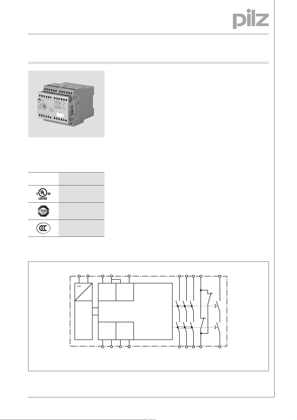
PNOZ V
Gertebild
][Bildunterschrift_nur_Not-Halt
Safety relay for monitoring E-STOP
pushbuttons
Approvals
PNOZ V
Unit features
Gertemerkmale
Positive-guided relay outputs:
– 3 safety contacts (N/O), instanta-
neous
– 1 safety contact (N/O), delay-on
de-energisation
– 1 auxiliary contact (N/C), instan-
taneous
Connection options for:
– E-STOP pushbutton
– Safety gate limit switch
Delay-on de-energisation, fixed or
adjustable
LED indicator for:
– Switch status channel 1/2
– Supply voltage
See order reference for unit types
Unit description
Bestimmung/Gertebeschreibung NOT-AUS, Schutz_PNOZ
The safety relay meets the requirements of EN 60947-5-1, EN 60204-1
and VDE 0113-1 and may be used in
applications with
E-STOP pushbuttons
Safety gates
Safety features
][Sicherheitseigenscha ften Schaltgerät_allgem einer Teil
The relay meets the following safety
requirements:
The circuit is redundant with built-in
self-monitoring.
The safety function remains effec-
tive in the case of a component failure.
The correct opening and closing of
the safety function relays is tested
automatically in each on-off cycle.
Sicherheitseigenschaften Zusatz - Sicherung DC_PNOZ
The unit has an electronic fuse.
Zulassungen
Block diagram
Blockschaltbild
Pilz GmbH & Co. KG, Felix-Wankel-Straße 2, 73760 Ostfildern, Germany
Telephone: +49 711 3409-0, Telefax: +49 711 3409-133, E-Mail: pilz.gmbh@pilz.de
1002057-EN-02-2011-06
Page 2
E-STOP relays, safety gate monitors
POWER
Input
Output safe
Reset/Start
t1 t2
t1
t2
t2
t1
t1 t2
1 2
ab
t3
R
lmax
Rl / km
I
max
=
Up to PL e of EN ISO 13849-1
PNOZ V
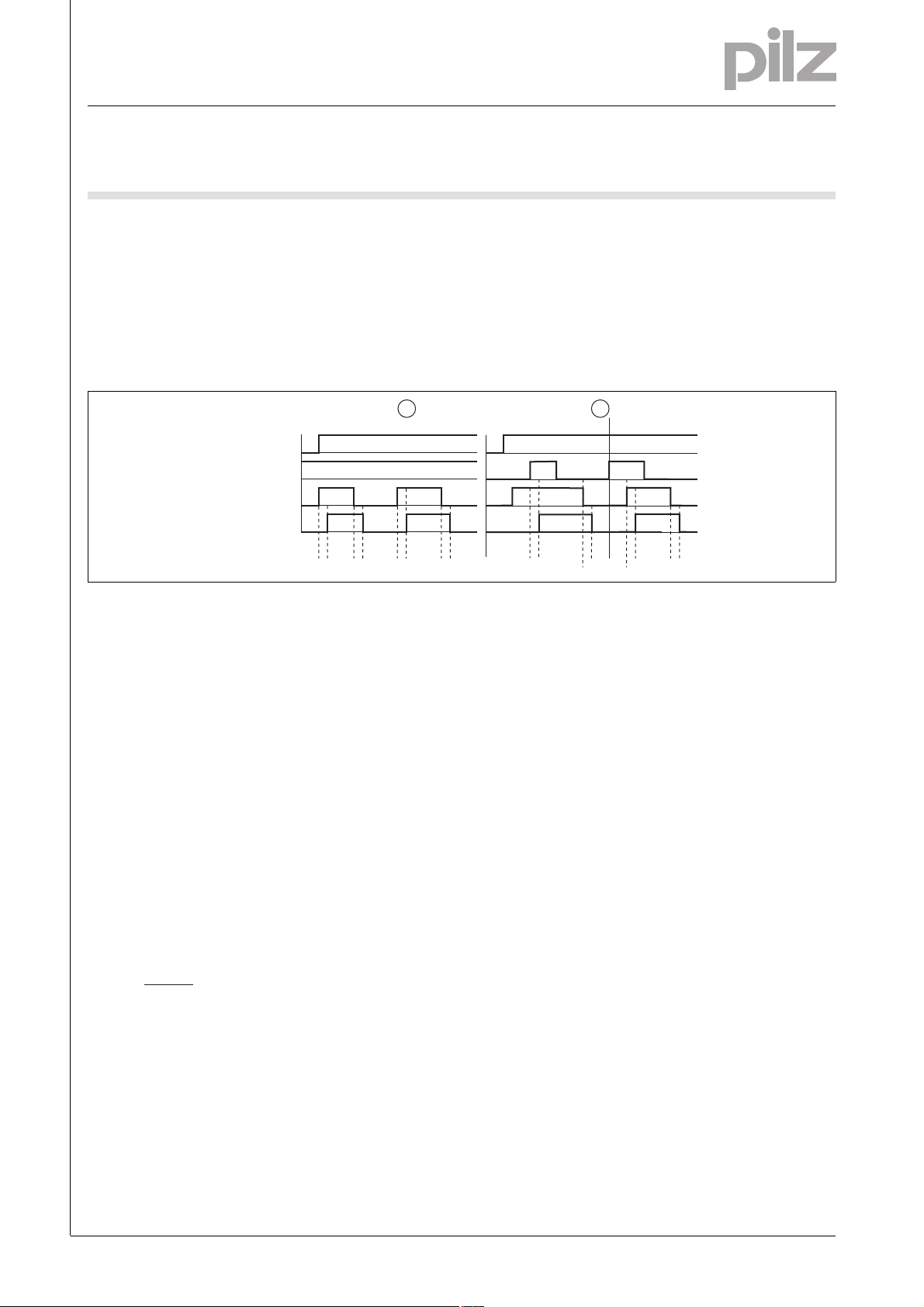
Function description
][Funktionen_einkanalig_Erd_Start
Single-channel operation: no re-
dundancy in the input circuit, earth
faults in the reset circuit are detected.
][Funktionen_zweikanalig_ohne_quer
Timing diagram
Key
Power: Supply voltage
Reset/Start: Reset circuit S33-S34
Input: Input circuits S11-S12
Output safe: Safety contacts
: Automatic reset
Dual-channel operation without de-
tection of shorts across contacts:
redundant input circuit, detects
– earth faults in the reset and input
circuit,
– short circuits in the input circuit
and, with a monitored reset, in
][Zeitdiagramm_auto_manu
: Manual reset
a: Input circuit closes before reset
circuit
b: Reset circuit closes before input
circuit
the reset circuit too.
][Funktionen_autoStart
Automatic start: Unit is active once
the input circuit has been closed.
][Funktionen_manuStart
Manual reset: Unit is active once
the input circuit is closed and then
the reset circuit is closed.
: Switch-on delay
t
1
t2: Delay-on de-energisation
: Recovery time
t
3
Wiring
][Verdrahtung_Si_verz
Please note:
Information given in the “Technical
details” must be followed.
Outputs 13-14, 23-24, 33-34, 57-58
are delay-on de-energisation safety
contacts.
To prevent contact welding, a fuse
should be connected before the
output contacts (see technical details).
Calculation of the max. cable runs
in the input circuit:
I
max
R
= max. overall cable resist-
lmax
ance (see technical details)
/ km = cable resistance/km
R
l
Use copper wire that can withstand
60/75 °C.
Sufficient fuse protection must be
provided on all output contacts with
capacitive and inductive loads.
Telephone: +49 711 3409-0, Telefax: +49 711 3409-133, E-Mail: pilz.gmbh@pilz.de
1002057-EN-02-2011-06Pilz GmbH & Co. KG, Felix-Wankel-Straße 2, 73760 Ostfildern, Germany
-2
Page 3
E-STOP relays, safety gate monitors
A1
L+
A2
L-
S1
S11
S22
S12
S1
S11
S12
S22
S1
S11
S22
S12
S1
S2
S11
S12
S22
S33
S34
S2S1
S33
S34
S33
S34
S3
S33
S34
S3
Up to PL e of EN ISO 13849-1
PNOZ V
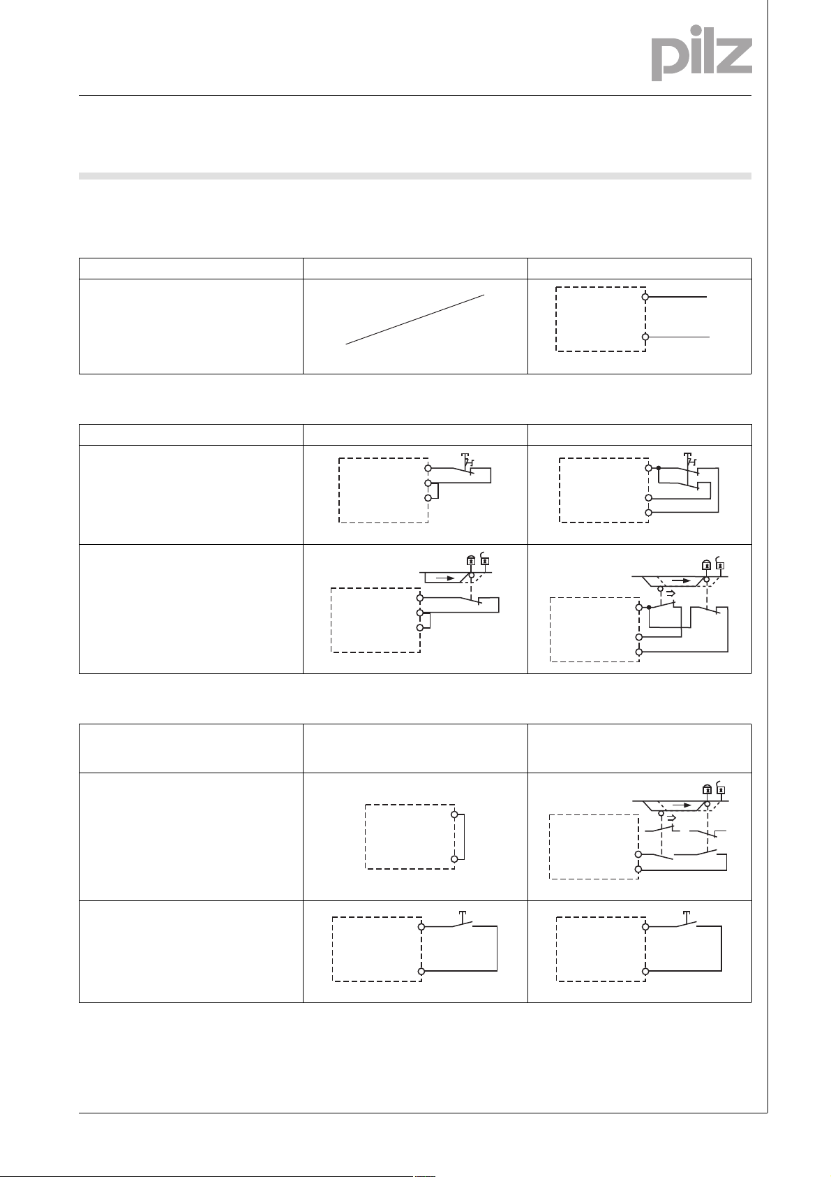
Preparing for operation
Betriebsbereitschaft her stellen
Supply voltage
Supply voltage AC DC
Input circuit
Input circuit Single-channel Dual-channel
E-STOP
without detection of shorts across contacts
Safety gate
without detection of shorts across contacts
Reset circuit
Reset circuit E-STOP wiring
(single-channel, dual-channel)
Safety gate (single-channel)
Automatic reset
Manual reset
Safety gate (dual-channel)
Pilz GmbH & Co. KG, Felix-Wankel-Straße 2, 73760 Ostfildern, Germany
Telephone: +49 711 3409-0, Telefax: +49 711 3409-133, E-Mail: pilz.gmbh@pilz.de
1002057-EN-02-2011-06
Page 4
E-STOP relays, safety gate monitors
Y1
Y2
K5
K6
K5
L1
N
K6
Y1
13 (23, 33, 57)
Y2
14 (24, 34, 58)
Up to PL e of EN ISO 13849-1
PNOZ V
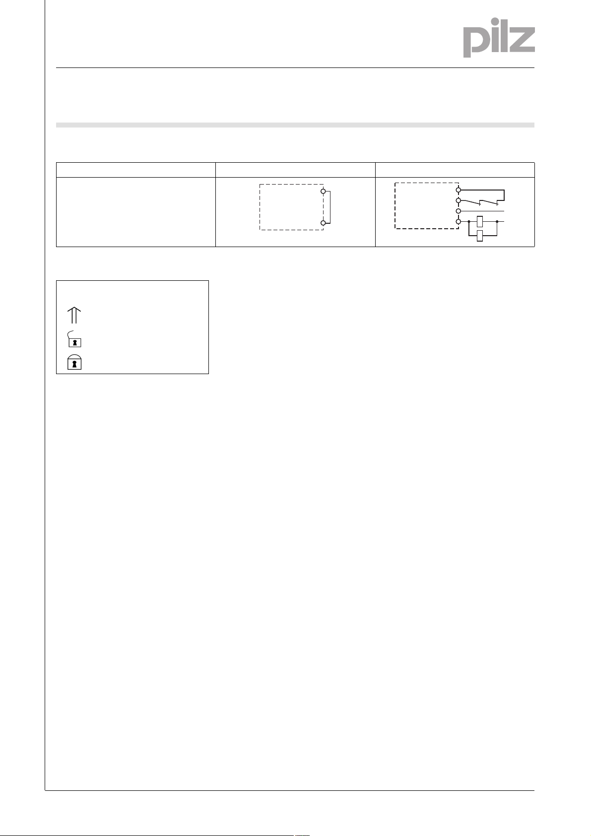
Feedback circuit
Feedback circuit without feedback loop with feedback loop
Link or contacts from external
contactors
Key
S1 E-STOP pushbutton
S3 Reset button
Switch operated
Gate open
Gate closed
Telephone: +49 711 3409-0, Telefax: +49 711 3409-133, E-Mail: pilz.gmbh@pilz.de
1002057-EN-02-2011-06Pilz GmbH & Co. KG, Felix-Wankel-Straße 2, 73760 Ostfildern, Germany
-4
Page 5
E-STOP relays, safety gate monitors
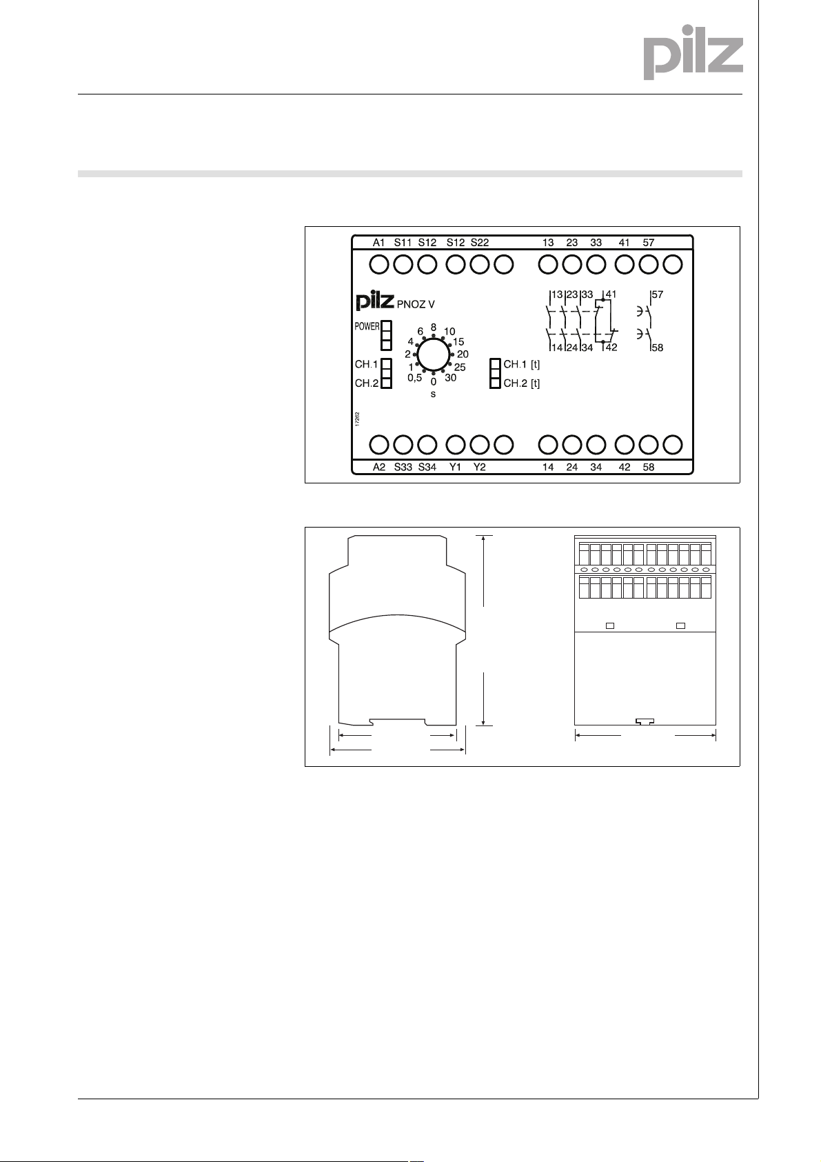
121 (4.76")
75 (2.95")
87 (3.42")
90 (3.54")
Up to PL e of EN ISO 13849-1
PNOZ V
Terminal configuration
Klemmenbelegung
Installation
Montage_PNOZ_X
The safety relay should be installed
in a control cabinet with a protection type of at least IP54.
Use the notch on the rear of the unit
to attach it to a DIN rail.
Ensure the unit is mounted securely
on a vertical DIN rail (35 mm) by using a fixing element (e.g. retaining
bracket or an end angle).
Dimensions
Abmessungen
Pilz GmbH & Co. KG, Felix-Wankel-Straße 2, 73760 Ostfildern, Germany
Telephone: +49 711 3409-0, Telefax: +49 711 3409-133, E-Mail: pilz.gmbh@pilz.de
1002057-EN-02-2011-06
Page 6

E-STOP relays, safety gate monitors
10
1
10 100 1000 10000
0.1
DC13: 24 V
AC15: 230 V
AC1: 230 V
DC1: 24 V
AC1: 400 V
D Nennbetriebstrom (A)
GB Nominal operating current (A)
F Courant coupé (A)
E Corriente nominal de servicio (A)
I Corrente di esercizio nominale (A)
NL Nominale bedrijfsstroom (A)
D Schaltspielzahl x 10
3
GB Cycles x 10
3
F Nombre de manuvres x 10
3
E Número de ciclos x 10
3
I Numero dei cicli di commutazione x 10
3
NL Aantal schakelingen x 10
3
Up to PL e of EN ISO 13849-1
PNOZ V
Notice
][WICHTIG_PDB_al t
This data sheet is only intended for use
during configuration. For installation
and operation, please refer to the operating instructions supplied with the
unit.
][Technische Daten PNOZ
Technical details
Electrical data
Supply voltage
Supply voltage U
Voltage tolerance -15 %/+10 %
Power consumption at U
Residual ripple DC 160 %
Voltage and current at
Input circuit DC: 24.0 V 50.0 mA
Reset circuit DC: 24.0 V 40.0 mA
Feedback loop DC: 24.0 V 40.0 mA
Number of output contacts
Safety contacts (S) instantaneous: 3
Safety contacts (N/O), delayed: 1
Auxiliary contacts (N/C): 1
Utilisation category in accordance with EN 60947-4-1
Safety contacts: AC1 at 240 V I
Safety contacts: AC1 at 400 V I
Safety contacts: DC1 at 24 V I
Safety contacts, delayed: AC1 at 240 V I
Safety contacts, delayed: DC1 at 24 V I
Auxiliary contacts: AC1 at 240 V I
Auxiliary contacts: DC1 at 24 V I
Utilisation category in accordance with EN 60947-5-1
Safety contacts: AC15 at 230 V I
Safety contacts: DC13 at 24 V (6 cycles/min) I
Safety contacts, delayed: AC15 at 230 V I
Safety contacts, delayed: DC13 at 24 V (6 cycles/min) I
Auxiliary contacts: AC15 at 230 V I
Auxiliary contacts: DC13 at 24 V (6 cycles/min) I
Telephone: +49 711 3409-0, Telefax: +49 711 3409-133, E-Mail: pilz.gmbh@pilz.de
Service life graph
DC 24 V
B
DC 5.0 W
B
: 0.01 A , I
min
: 2000 VA
P
max
: 0.01 A , I
min
P
: 2000 VA
max
: 0.01 A , I
min
P
: 200 W
max
: 0.01 A , I
min
: 1000 VA
P
max
: 0.01 A , I
min
P
: 100 W
max
: 0.01 A , I
min
P
: 2000 VA
max
: 0.01 A , I
min
: 200 W
P
max
: 5.0 A
max
: 7.0 A
max
: 4.0 A
max
: 4.0 A
max
: 5.0 A
max
: 7.0 A
max
max
max
max
max
max
max
max
Lebensdauerkurve
: 8.0 A
: 5.00 A
: 8.0 A
: 4.0 A
: 4.0 A
: 8.0 A
: 8.0 A
1002057-EN-02-2011-06Pilz GmbH & Co. KG, Felix-Wankel-Straße 2, 73760 Ostfildern, Germany
-6
Page 7
E-STOP relays, safety gate monitors
Up to PL e of EN ISO 13849-1
PNOZ V
Electrical data
Contact material AgSnO2 + 0.2µ Au
External contact fuse protection (I
Blow-out fuse, quick
Safety contacts: 10 A
Safety contacts, delayed: 6 A
Auxiliary contacts: 10 A
Blow-out fuse, slow
Safety contacts: 6 A
Safety contacts, delayed: 4 A
Auxiliary contacts: 6 A
Circuit breaker 24 VAC/DC, characteristic B/C
Safety contacts: 6 A
Safety contacts, delayed: 4 A
Auxiliary contacts: 6 A
Max. overall cable resistance R
input circuits, reset circuits
single-channel at U
dual-channel without detect. of shorts across contacts at U
Safety-related characteristic data
PL in accordance with EN ISO 13849-1: 2006
Safety contacts, instantaneous PL e (Cat. 4)
Safety contacts, delayed <30 s PL d (Cat. 3)
Safety contacts, delayed ≥30 s PL c (Cat. 1)
Category in accordance with EN 954-1
Safety contacts, instantaneous Cat. 4
Safety contacts, delayed <30 s Cat. 3
Safety contacts, delayed ≥30 s Cat. 1
SIL CL in accordance with EN IEC 62061
Safety contacts, instantaneous SIL CL 3
Safety contacts, delayed <30 s SIL CL 3
Safety contacts, delayed ≥30 s SIL CL 1
PFH in accordance with EN IEC 62061
Safety contacts, instantaneous 2.31E-09
Safety contacts, delayed <30 s 2.64E-09
Safety contacts, delayed ≥30 s 2.87E-09
SIL in accordance with IEC 61511
Safety contacts, instantaneous SIL 3
Safety contacts, delayed <30 s SIL 3
Safety contacts, delayed ≥30 s SIL 2
PFD in accordance with IEC 61511
Safety contacts, instantaneous 2.03E-06
Safety contacts, delayed <30 s 1.26E-05
Safety contacts, delayed ≥30 s 4.64E-05
T
[year] in accordance with EN ISO 13849-1: 2006 20
M
Times
Switch-on delay
with automatic reset typ. 140 ms
with automatic reset max. 200 ms
with automatic reset after power on typ. 150 ms
with automatic reset after power on max. 220 ms
with manual reset typ. 160 ms
with manual reset max. 200 ms
Delay-on de-energisation
with E-STOP typ. 15 ms
with E-STOP max. 30 ms
with power failure typ. 50 ms
with power failure max. 100 ms
DC 100 Ohm
B
= 1 kA) to EN 60947-5-1
K
lmax
DC 200 Ohm
B
Pilz GmbH & Co. KG, Felix-Wankel-Straße 2, 73760 Ostfildern, Germany
Telephone: +49 711 3409-0, Telefax: +49 711 3409-133, E-Mail: pilz.gmbh@pilz.de
1002057-EN-02-2011-06
Page 8
E-STOP relays, safety gate monitors
Up to PL e of EN ISO 13849-1
PNOZ V
Times
Recovery time at max. switching frequency 1/s
after E-STOP 50 ms +tv
after power failure 150 ms
Delay time t
Repetition accuracy 2 %
Time accuracy -15 %/+15 % +50 ms
Simultaneity, channel 1 and 2 75 ms
Supply interruption before de-energisation 20 ms
Environmental data
EMC EN 60947-5-1, EN 61000-6-2
Vibration to EN 60068-2-6
Frequency 10 - 55 Hz
Amplitude 0.35 mm
Climatic suitability EN 60068-2-78
Airgap creepage in accordance with EN 60947-1
Pollution degree 2
Overvoltage category III
Rated insulation voltage 250 V
Rated impulse withstand voltage 4.00 kV
Ambient temperature -10 - 55 °C
Storage temperature -40 - 85 °C
Protection type
Mounting (e.g. cabinet) IP54
Housing IP40
Terminals IP20
Mechanical data
Housing material
Housing PPO UL 94 V0
Front ABS UL 94 V0
Cross section of external conductors with screw terminals
1 core flexible 0.20 - 4.00 mm² , 24 - 10 AWG
2 core, same cross section, flexible:
with crimp connectors, without insulating sleeve 0.20 - 2.50 mm² , 24 - 14 AWG
without crimp connectors or with TWIN crimp connectors 0.20 - 2.50 mm² , 24 - 14 AWG
Torque setting with screw terminals 0.60 Nm
Dimensions
Height 87.0 mm
Width 90.0 mm
Depth 121.0 mm
Weight 471 g No. 774791
Technische Daten_Satz No .
No. stands for order number.
Technische Daten_Satz No rmen
The standards current on 2008-10 apply.
][Dauerstrom_DC
: selectable 0,10 s; 0,20 s; 0,30 s; 0,40 s; 0,50 s; 0,60 s; 0,70 s; 0,80 s; 1,00 s;
V
1,50 s; 2,00 s; 3,00 s No. 774789
0,00 s; 0,50 s; 1,00 s; 2,00 s; 4,00 s; 6,00 s; 8,00 s; 10,00 s;
15,00 s; 20,00 s; 25,00 s; 30,00 s No. 774790
0,00 s; 5,00 s; 10,00 s; 20,00 s; 40,00 s; 60,00 s; 80,00 s;
100,00 s; 150,00 s; 200,00 s; 250,00 s; 300,00 s No. 774791
480 g No. 774789, 774790
Telephone: +49 711 3409-0, Telefax: +49 711 3409-133, E-Mail: pilz.gmbh@pilz.de
1002057-EN-02-2011-06Pilz GmbH & Co. KG, Felix-Wankel-Straße 2, 73760 Ostfildern, Germany
-8
Page 9

E-STOP relays, safety gate monitors
Up to PL e of EN ISO 13849-1
PNOZ V
Conventional thermal current
(A) at UBDC
I
th
1 contact 8.00 A
2 contacts 7.40 A
3 contacts 6.00 A
4 contacts 4.00 A
Order reference
Type Features Terminals Order no.
PNOZ V 24 V DC 3 s selectable Screw terminal 774 789
PNOZ V 24 V DC 30 s selectable Screw terminal 774 790
PNOZ V 24 V DC 300 s selectable Screw terminal 774 791
Bestelldaten
Pilz GmbH & Co. KG, Felix-Wankel-Straße 2, 73760 Ostfildern, Germany
Telephone: +49 711 3409-0, Telefax: +49 711 3409-133, E-Mail: pilz.gmbh@pilz.de
1002057-EN-02-2011-06
 Loading...