


ER803F
PANJIT ER803F, ER802F, ER804F, ER801F, ER801AF Datasheet
...
ER800F THRU ER804F
ISOLA TION SUPERFAST RECOVERY RECTIFIERS
VOLTAGE - 50 to 400 Volts CURRENT - 8.0 Amperes
F
E
A
T
U
R
E
S
l
Plastic package has Underwriters Laboratory
Flammability Classification 94V-O utilizing
Flame Retardant Epoxy Molding Compound
l
Exceeds environmental standards of MIL-S-19500/228
l
Low power loss, high efficiency
l
Low forward voltage, high current capability
l
High surge capacity
l
Super fast recovery times, high voltage
l
Epitaxial chip construction
M
E
C
H
A
N
I
C
A
L
D
A
T
A
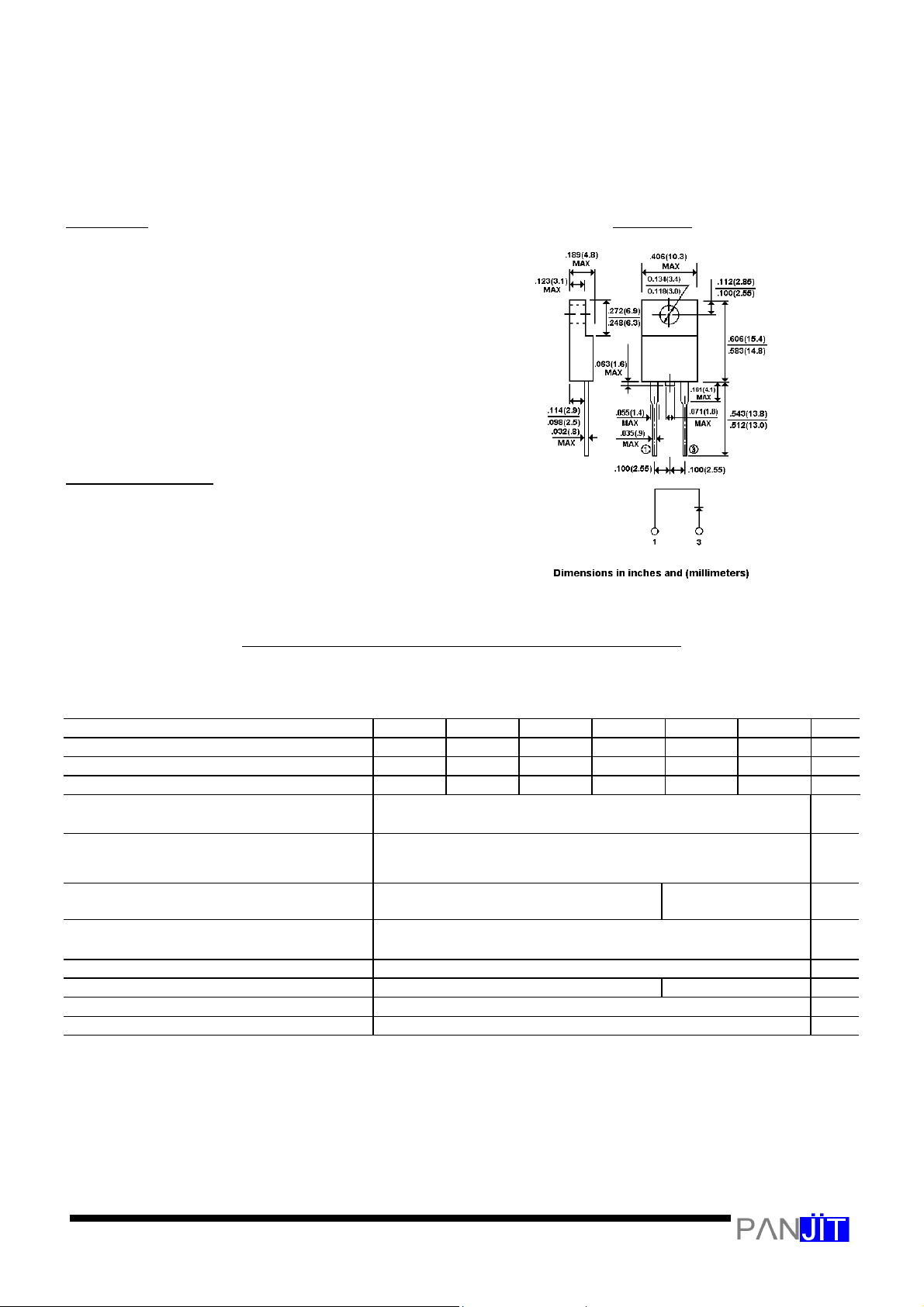
Case: ITO-220AC full molded plastic package
Terminals: Leads, solderable per MIL-STD-202, Method 208
Polarity: As marked
Mounting Position: Any
Weight: 0.08 ounce, 2.24 grams
M
A
X
I
M
U
M
R
A
T
I
N
G
S
A
N
D
E
L
E
C
T
R
I
C
A
L
C
H
A
R
A
C
T
E
R
I
S
T
I
C
S
Ratings at 25
¢J
ambient temperature unless otherwise specified.
Single phase, half wave, 60Hz, Resistive or inductive load.
For capacitive load, derate current by 20%.
E
R
8
0
0
F
E
R
8
0
1
F
E
R
8
0
1
A
F
E
R
8
0
2
F
E
R
8
0
3
F
E
R
8
0
4
F
UNITS
Maximum Recurrent Peak Reverse Voltage 50 100 150 200 300 400
V
Maximum RMS Voltage 35 70 105 140 210 320
V
Maximum DC Blocking Voltage 50 100 150 200 300 400
V
Maximum Average Forward Rectified
Current at T
C
=100 ¢J
8.0
A
P
e
a
k
F
o
r
w
a
r
d
S
u
r
g
e
C
u
r
r
e
n
t
,
8
.
3
m
s
s
i
n
g
l
e
h
a
l
f
s
i
n
e
-
w
a
v
e
s
u
p
e
r
i
m
p
o
s
e
d
o
n
r
a
t
e
d
l
o
a
d
(
J
E
D
E
C
m
e
t
h
o
d
)
125
A
Maximum Forward Voltage at 8.0A per
element
0.95 1.30
V
M
a
x
i
m
u
m
D
C
R
e
v
e
r
s
e
C
u
r
r
e
n
t
a
t
T
a
=25 ¢J
D
C
B
l
o
c
k
i
n
g
V
o
l
t
a
g
e
p
e
r
e
l
e
m
e
n
t
T
a
=
1
2
5
¢J
10
500
£g
A
T
y
p
i
c
a
l
J
u
n
c
t
i
o
n
c
a
p
a
c
i
t
a
n
c
e
(
N
o
t
e
1
)
62
P
F
M
a
x
i
m
u
m
R
e
v
e
r
s
e
R
e
c
o
v
e
r
y
T
i
m
e
(
N
o
t
e
2
)
35 50
ns
T
y
p
i
c
a
l
J
u
n
c
t
i
o
n
R
e
s
i
s
t
a
n
c
e
(
N
o
t
e
3
)
R
£K
J
C
3.0
¢J
/
W
O
p
e
r
a
t
i
n
g
a
n
d
S
t
o
r
a
g
e
T
e
m
p
e
r
a
t
u
r
e
R
a
n
g
e
T
J
-55 to +150
¢J
NOTES:
1. Measured at 1 MHz and applied reverse voltage of 4.0 VDC
2. Reverse Recovery Test Conditions: I
F
=.5A, I
R
=1A, Irr=.25A
3. Thermal resistance junction to CASE
I
T
O
-
2
2
0
A
C
 Loading...