


CP1008
PANJIT CP1008, CP1001, CP1000, CP1006, CP1004 Datasheet
...
CP1000 THRU CP1008
SINGLE-PHASE SILICON BRIDGE
VOLTAGE - 50 to 800 Volts CURRENT - P.C. MTG 3A, HEAT-SINK MTG 10A
F
E
A
T
U
R
E
S
l
Surge overload rating—200 Amperes peak
l
Low forward voltage drop and reverse leakage
l
Small size, simple installation
l
Plastic package has Underwriter Laboratory
Flammability Classification 94V-O
l
Reliable low cost construction utilizing molded
plastic technique
M
E
C
H
A
N
I
C
A
L
D
A
T
A
Case: Molded plastic with heatsink integrally
mounted in the bridge encapsulation
Terminals: Leads solderable per MIL-STD-202,
Method 208
Weight: 0.21 ounce, 6.1 grams
M
A
C
X
I
M
U
M
R
A
T
I
N
G
S
A
N
D
E
L
E
C
T
R
I
C
A
L
C
H
A
R
A
C
T
E
R
I
S
T
I
C
S
At 25 ¢J ambient temperature unless otherwise noted; resistive or inductive load at 60Hz .
CP1000 CP1001 CP1002 CP1004 CP1006 CP1008 UNITS
Max Recurrent Peak Rev Voltage 50 100 200 400 600 800 V
Max Bridge Input Voltage RMS 35 70 140 280 420 560 V
Max Average Rectified Output at T
C
=50 ¢J*
See Fig. 2 at T
C
=100
¢J
*
at T
A
=50 ¢J**
10.0
3.0
3.0
A
A
Peak One Cycle Surge Overload Current 200 A
Max Forward Voltage Drop per element at
5.0A DC & 25
¢J
. See Fig. 3
1.1 V
Max Rev Leakage at rated Dc Blocking
Voltage per element at 25
¢J
See Fig 4 at100 ¢J
10.0
1.0
£g A
m
A
T
y
p
i
c
a
l
j
u
n
c
t
i
o
n
c
a
p
a
c
i
t
a
n
c
e
p
e
r
l
e
g
(
N
o
t
e
4
)
C
J
200
P
F
I
2
t Rating for fusing ( t<8.3ms) 164 A
2
S
Typical Thermal Resistance (Note 2) R £KJA
Typical Thermal Resistance (Note 3) R
£K
JC
25
5
¢J/W
Operating Temperature Range -55 TO +125 ¢J
Storage Temperature Range -55 TO +150 ¢J
NOTES:
* Unit mounted on metal chassis.
** Unit mounted on P.C. board.
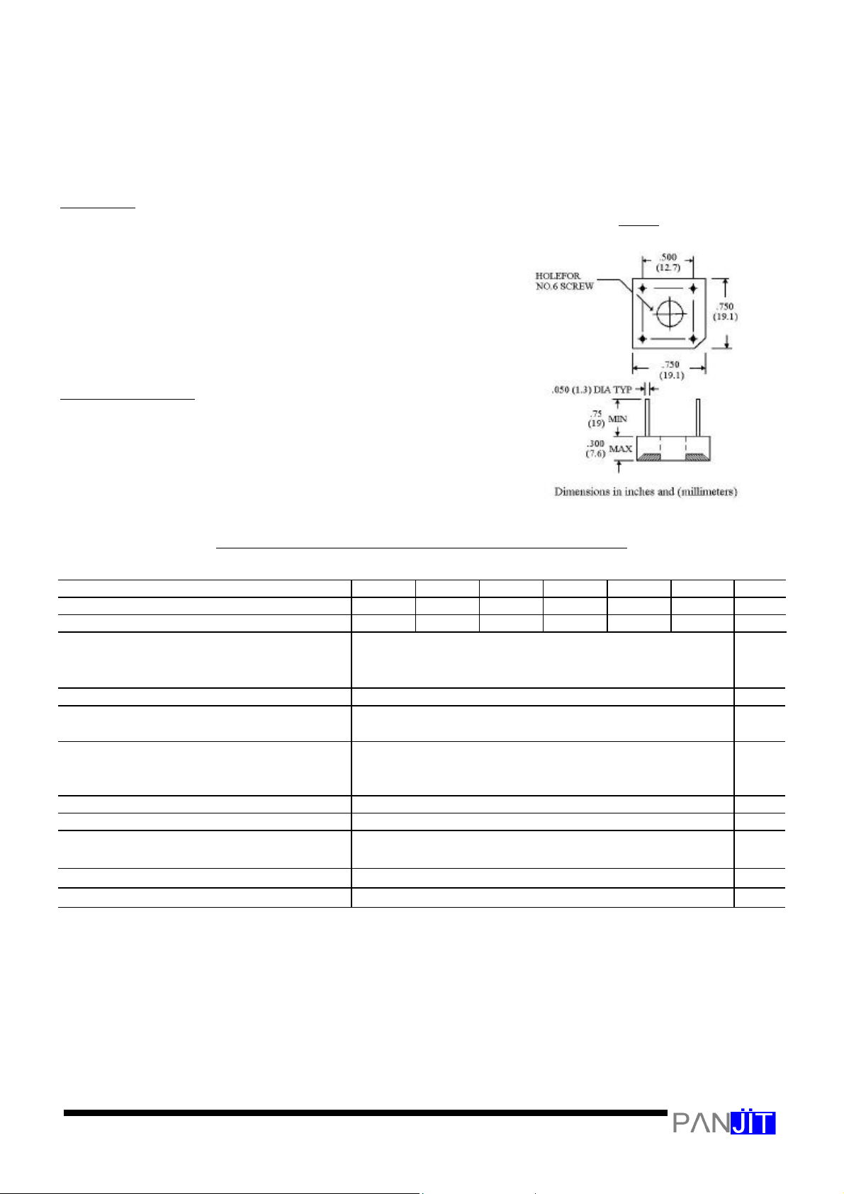
1. Recommended mounting position is to bolt down on heatsink with silicone thermal compound
for maximum heat transfer with #6 screw.
2. Units Mounted in free air, no heatsink. P.C.B at 0.375”(9.5mm) lead length with 0.5
¡Ñ
0.5”
(12
¡Ñ
12mm)copper pads.
3. Units Mounted on a 3.0
¡Ñ
3.0”
¡Ñ
0.11” thick (7.5
¡Ñ
7.5
¡Ñ
0.3cm) AL plate heatsink.
4. Measured at 1.0MHZ and applied reverse voltage of 4.0 volts.
C
P
-
1
0
 Loading...