


ER1004F
ER1000F THRU ER1004F
SUPERFAST RECOVER Y RECTIFIERS
VOL TAGE: 50 to 400 V olts CURRENT: 10.0 Amperes
FEATURES
• Plastic package has Underwriters Laboratory
Flammability Classification 94V-O utilizing
Flame Retardant Epoxy Molding Compound
• Exceeds environmental standards of MIL-S-19500/228
• Low power loss, high efficiency
• Low forward voltage, high current capability
• High surge capacity
• Super fast recovery times, high voltage
• Epitaxial chip construction
MECHANICAL DA TA
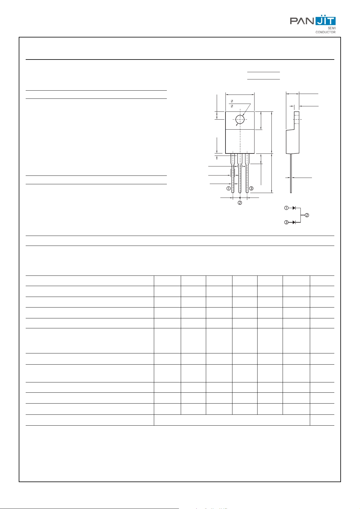
Case: ITO-220AB molded plastic
Terminals: Lead, solderable per MIL-STD-202, Method 208
Polarity: As marked
Mounting Position: Any
Weight: 0.08 ounces, 2.24 grams
MAXIMUM RA TINGS AND ELECTRICAL CHARACTERISTICS
Maximum Recurrent Peak Reverse Voltage
Maximum RMS Voltage
Maximum DC Blocking Voltage
Maximum Average Forward Recitified TC=100
O
C
Peak Forward Surge Current, IFM (surge):8.3ms
single half sine-wave superimposed on rated load
(JEDEC method)
Maximum Forward Voltage at 10.0A per element.
Maximum DC Reverse Current at Rated TA=25
O
C
DC Blocking Voltage per element TA=125
O
C
Typical Junction capacitance (Note 1)
Maximum Reverse Recovery Time(Note 2)
Typical Junction Resistance(Note 3) RθJC
Operating and Storage Temperature Range TJ
Ratings at 25
O
C ambient temperature unless otherwise specified.
Single phase, half wave, 60Hz, Resistive or inductive load.
For capacitive load, derate current by 20%.
ER1000F ER1001F ER1001AF ER1002F ER1003F ER1004F UNITS
50 100 150 200 300 400 V
35 70 105 140 210 320 V
50 100 150 200 300 400 V
10 10 10 10 10 10 A
75 75 75 75 75 75 A
0.95 0.95 0.95 0.95 1.30 1.30 V
10 10 10 10 10 10 µA
500 500 500 500 500 500 µA
62 62 62 62 62 62 PF
35 35 35 35 50 50 n s
3.0 3.0 3.0 3.0 3.0 3.0
O
C/W
-55 to +150
O
C
ITO-220AB
.406(10.3) MAX
.606(15.4)
.583(14.8)
.272(6.9)
.248(6.3)
.543(13.8)
.512(13.0)
.035(.9) MAX
.134(3.4)
.161(4.1) MAX
.189(4.8)
MAX
.1
(2.54) (2.54)
.1
.112(2.85)
.100(2.55)
.118(3.0)
.055(1.4) MAX
.071(1.8) MAX
.123(3.1)
MAX
.032(.8)
MAX
.063(1.6)
MAX
AC
AC
+
Positive CT
NOTES:
1. Measured at 1 MHz and applied reverse voltage of 4.0 VDC
2. Reverse Recovery Test Conditions: IF=.5A, IR=1A, Irr=0.25A
3. Thermal resistance junction to CASE
 Loading...