

Panasonic TX-D7F21 User Manual [en, es, fr]
Operating instructions
Mode d’empioi
Manuai de Instrucciones
Multi-Scan Color Monitor
TM
MODEL TX-D7F21
Panasonic
These Operating Instructions are for units for sale and use in
the United States of America and Canada only.
Read these instructions completely before operating this display monitor.

IMPORTANT NOTICE CONCERNING POWER CORD SELECTION
The power cord for this unit has been packed separately and has been selected according to the
country of destination and must be used to prevent electric shock. Use the following guidelines if it is
necessary to replace the original cord set.
The female receptacle of the cord set must meet CEE-22 requirements and will look like Figure 1:
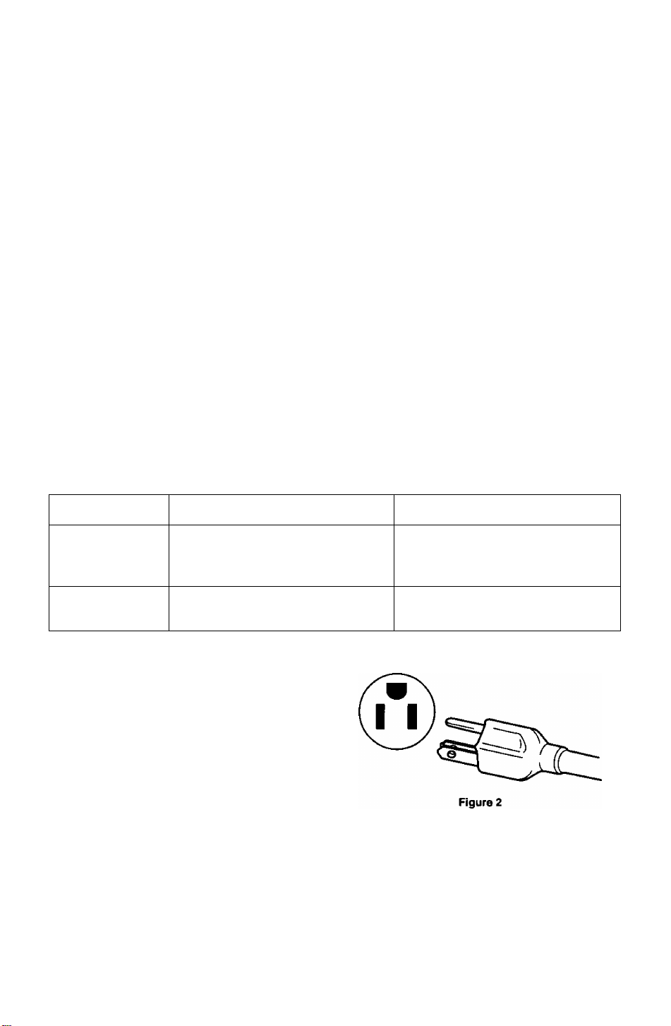
For the United States and Canada
In the United States and Canada the male plug is a NEMA 5-15 style {Figure 2) and is UL listed and
CSA labelled. For units which are mounted on a desk or table, type SVT or SJT cord sets may be
used. For units which sit on the floor, only SJT type cord sets may be used. The cord set must be
selected according to the current rating for your unit. Please consult Table A for the selection criteria
for power cords used in the United States and Canada. (The cord set is marked with its Cord Type.)
For European Countries:
In Europe you must use a cord set which is appropriate for the receptacles in your country.
The cord set is HAR-Certifled, and the mark 4 HAR ^ will appear on the outer sheath, or on
the insulation of one of the inner conductors.
If you have any questions concerning the proper power cord to use, please consult with the dealer
from whom you purchased your unit.
Table A
Cord Type Size of Conductors In Cord
SJT
SVT
18AWG
16AWG 12Amps
14AWG 12Amps
18AWG 10Amps
17AWG 12Amps
Figure 1
Maximum Current Rating of Unit
10Amps

Federal Communications Commission Requirements
This equipment has been tested and found to comply with the limits for Class B digital devices, pursuant
to Part 15 of the FCC Rules. These limits are designed to provide reasonable protection against harmful
interference in a residential installation. This equipment generates, uses, and can radiate radio frequency
energy and, if not installed and used in accordance with the instructions, may cause harmful interference
to radio communications. However, there is no guarantee that interference will not occur in a particular
installation. If this equipment does cause harmful interference to radio or television reception, which can
be determined by turning the equipment off and on, the user is encouraged to try to correct the
interference by one or more of the following measures:
- Reorient or relocate the receiving antenna.
- Increase the separation between the equipment and receiver.
- Connect the equipment into an outlet on a circuit different from that to which the receiver is
connected.
- Consult the dealer or an experienced radio/TV technician for help.
FCC Warning:
To assure continued FCC compliance, the user must use the provided grounded power supply
cord and shielded interface cable with bonded ferrite cores. Also, any unauthorized changes or
modifications to this monitor would void the user’s authority to operate this device.
As an Energy Star* partner, Panasonic Computer Peripheral Company has determined that
this product meets the Energy Star* guidelines for energy efficiency.

A A
To avoid the risk of severe eiectricai shock inciuding death, do not remove
covers (or back) of monitor. No user serviceabie parts are inside.
Refer servicing to quaiified service personnel.
Danger
AA
To prevent ris
Never place any object on the monitor, AC line cord, or cause the cords to make
sharp bends, or otherwise do anything that can affect the integrity of the cords.
Always remove the line cord from the socket by holding the plug, not the cord.
Do not place anything containing any liquid (even a wet or damp cloth) on the
monitor as the introduction of fluids can create an electrical hazard. Do not
expose the monitor to rain or moisture.
Do not place the monitor with less than the recommended clearance (see
Precautions, 1 Installation Page 2). Do not block the ventilation openings with
anything. Do not insert any objects into the ventilation openings.
Warnings
k of eiectric shock and possibie fire:
Customer’s Record
The serial number of this product is printed on its back cover label.
Note this serial number in the space provided and retain this booklet as a permanent record of
your purchase to aid in identification of the unit in the event of theft or loss.
Model number : TX-D7F21
Serial number :
Table of Contents
IMPOFfTANT NOTICE CONCERNING POWER CORD SELECTION
Federal Communications Commission Requirements.......................................ii
Danger...............................................................................................................1
Warnings............................................................................................................1
Customer’s Record............................................................................................1
Table of Contents...............................................................................................1
Precautions 1)lnstallation...................................................................................2
Precautions 2)Usage..........................................................................................2
Precautions 3)Product Care...............................................................................2
Features..............................................................................................................3
Specifications......................................................................................................4
Installation...........................................................................................................5
Pin Assignment...................................................................................................6
External View......................................................................................................7
On-Screen Adjustment.......................................................................................8
Operation ...........................................................................................................9
Power Management System ...........................................................................13
Memories..........................................................................................................13
Timing Specifications........................................................................................14
Trouble Shooting ..............................................................................................17
Technical Support ............................................................................................18
Index ................................................................................................................18
..............
i
ALL PRODUCT/BRAND NAMES ARE TRADEMARKS OR REGISTERED TRADEMARKS OF THE RESPECTIVE HOLDERS.
© 1998 MATSUSHITA ELECTRIC INDUSTRIAL Co., Ltd.
-1 -

Precautions
1) Installation
• Install the monitor in a well ventilated place. Avoid exposing to direct sunlight, a heater,
or any other heat source. Heat will adversely affect the cabinets and the parts inside.
• Position the display unit so that the holes in the cabinet will not be blocked during use.
• Keep the display unit away from the kitchen, bathroom, washing machine, or other
sources of exposure to water, steam or moisture.
• In order to use the display unit safely, use only the supplied AC Power cord. The AC
Power cord must be used with a properly grounded and polarized power supply
socket. The AC Power cord supplied is for the USA (UL) and Canada (CSA) for use
with the display unit. For use in other countries, make sure the AC Power cord meets
the safety standards of the country.
• Place the AC Power cord where it will not be subject to stress.
• Use only Panasonic provided accessories or the exact equivalent.
2) Usage
• The monitor power switch does not completely turn off the AC Power to the monitor’s
circuits and places the monitor into a stand-by mode, which consumes about 0.1 W.
This stand-by mode gives no operation until the power switch is turned ON.
To totally remove power, the AC Power cord must be disconnected completely.
• Pulling on the AC Power cord or VGA Signal Cable can damage the display unit
(monitor) and can cause the unit to fall and possibly cause personal injury.
• Receiving trouble.
If there is a television set or other display unit nearby, keep your display unit as far
away from it as possible. Mutual interference can cause image distortion or noise.
• Long exposure to rubber or vinyl products can stains the cabinet.
• Keep the monitor from physical shock when moving. Be careful of the Cathode Ray
Tube (CRT).
• Do not place anything on the monitor.
• Also take good care of the AC Power cord:
Do not place any objects on the AC Power cord. Do not attempt to extend, shorten or
tie it into a knot.
3) Product Care
• Prior to cleaning your display unit, disconnect the AC Power cord and the VGA Signal
Cable from the display unit.
• Use a clean, soft, dry cloth to clean the outside of the monitor or the CRT surface.
If the monitor or CRT surface is very dirty, wet a clean, soft cloth with neutral detergent
(such as dishwashing detergent) and water, squeeze it tight until almost dry, wipe the
monitor or CRT surface with it, and finish by wiping with a clean dry cloth. Do not use
any solvents.
• Do not rub or strike the monitor with anything hard or harsh as this may scratch, mar or
damage the monitor permanently.
• Do not use a chemical duster or polish-cleaner because it can adversely affect the unit
and peel the paint coat.
-2-

Digital adjustment using the On-Screen Display
1)
• The on-screen menu is available in 3 languages. French, English, or Spanish can be selected.
• Custom adjustments can be made quickly and easily through the on-screen menu utilizing four buttons on
the front panel.
• The on-screen main menu ailovirs these adjustments to be made easily by scrolling through the Icons to
select an adjustment menu. The choice bar is located at the bottom of the main menu and it shows the
currently selected adjustment menu's name.
• Set the on-screen menus at any one of six location on the display screen.
The Plug & Play E70 is a DDC 1/2B* compatible monitor that uses VESA* (Video Electronics Standards
2)
Association) DDC ^{Display Data Channel) standard. This allows the E70 to Inform a compatible host of
its capabilities which meet the Microsoft* / Intel* Plug & Play Definition used by vyindows*95.
Power Management
3)
• A power management circuit conforming to the VESA DPMS standard is incorporated into the monitor.
Power consumption of the monitor can be lowered when using it in combination with a video board that
meets the DPMS standard.
• This product conforms to the Energy Star* program.
As an Energy Star? partner, Panasonic Computer Peripheral Company has determined that this product
meets the Energy Star* guidelines for energy efficiency.
4)
Environmentally Friendly
• Alt the plastic parts are recyclable.
Low emissions and static prevention
5)
• The display unit meets the strict Swedish (SWEDAC) MPR II guidelines for lower ELF and VLF magnetic
fields and alternating electric fields.
• Anti-static coating of the cathode ray tube (CRT) reduces electrostatic charge buildup. This prevents
electrostatic shocks when touching the CRT screen and reduces dust buildup.
Color adjusting function
6)
• The white reference color temperature is 9300K + 8 MPCD, 7500K, 6500K, 5000K, or a User Color can be
selected. For example, the monitor colors can be adjusted to match the colors of output generated on a
color printer.
• The white balance of an image can be adjusted as desired by individual adjustment of the red(R) and
green(G) and blue(B) signals. This feature enables color matching.
PanaSync digital multi-scan
7)
• Horizontal frequencies of 30 kHz to 70 kHz and vertical frequencies of 50 Hz to 160 Hz can be
automatically tracked. The display unit is suited to VGA, SVGA, VESA, and high-resolution video boards of
1280(H) x1024(V)/60 Hz.
• Eight timing (1 preset and 7 reservation) selections have been preset by the factory for image size and
position. In addition there are 13 user programmable selections of timing.
Self-test menu
8)
• The display unit can be checked via the self-test menu displayed on the screen. This menu can be
accessed without a computer.
DQ-DAF Electron Gun with Hyperbolic focus compensation circuit
9)
• The exclusive DQ-DAF electron gun with a hyperbolic focus compensation circuit that controls the electron
beam is combined with an invar mask to display fine images over the entire area on the 17 inch
(16.0inch/40.6cm viewable), 0.27 mm dot pitch (H: 0.236 mm x V: 0.137 mm), flat and square screen.
10) Other features
• Automatic selection of synchronized input signals (separate or composite).
• An ergonomically designed tilt and swivel base to complement virtually any office design. The pan angle is
90 degrees to the right and left, and the tilt angle is 13 degrees up and 4 degrees down.
* VESA DDC
The E70 is a VESA DDC 1/2B type of display. The E70 is capable of continuously transmitting its EDID
(Extended Display Identification) using a uni-directional DDC 1 communications channel. In addition, the E70
can respond to a request for EDID, or complete VDIF (Video Display Interface), to be transmitted using DDC
2, Level B commands.
The EDID data contains the display identity and the basic display specifications. The VDIF data contains full
display specifications as defined in the VESA VDIF standard. If a DDC 2 capable host is detected by the E70,
it will switch to a bi-directional DDC 2 communications channel.
As required by the VESA DDC standard, once the E70 has switched from DDC 1 to DDC 2 it is incapable of
switching from DDC 2 back to DDC 1 unless the power is turned off.
-3 -
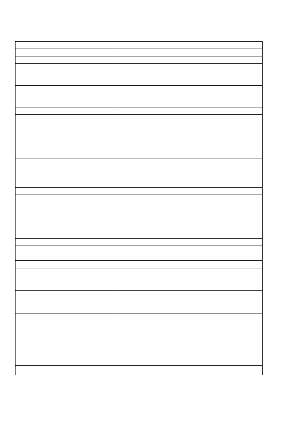
Specifications
CRT Size
Dot-pitch
Phosphor/Glass RGB short persistence (Hi-EV RED) Crystal pigment/Dark Tint
Surface treatment
Input signals Video signaling
Signal level 0.7 Vp-p (without sync, signal), 1.0 Vp-p (with sync, signal)
Sync signal
Horizontal Frequency Range
Vertical Frequency Range
Preset mode
Video Maximum Pixel Clock
Resolution
Viewable Image Size Factory preset
(H X V, Diagonal) Full scan (Typical)
Display Color
Connectors Video Signal
Power supply
Input power
Power consumption
Controls Front Power ON/OFF, |T|, a, B, ¡2} keys
On-Screen Display
Tilt/swivel
Dimensions ,(W x H x D)
Weight (monitor only)
Approvals
Standard ,
Environmental conditions
Operating Temperature
Humidity
Altitude
Storage Temperature
Humidity
Altitude
Windows*95 Plug & Play
Note:
*The on-screen image may flicker if the display Is operated with the Vertical freq. under 60 Hz .
‘‘Depends on signal timing used, see page 14 .
‘“Number of colors depends on the Video Board used, memory installed, and RAMDAC
{Random Access Memory Digital to Analog Converter),
Specifications and design are subject to change without notice.
This product may be subject to export regulations.
17“ CRT (16.0V40.6 cm Viewable Image Size) Flat Square
0.27 mm (H: 0.236 mm x V: 0.137 mm)
Advanced AGRAS (Anti-Glare, anti-Reflective and Anti-Static) Coat
RGB analog
HA/ separate (TTL level), H/V composite (TTL level),
Sync - on - Green is not available.
Allowable Frequency Range: 30.0 kHz to 70.0 kHz
Allowable Frequency Range: 50.0 Hz to 160.0 Hz
1 preset and 7 reservation (See page 15)
108 MHz (typ.)
1280 dots(H) X 1024 lines (V) at 60 Hz‘
11.81" X 8.86", 14.8" Diagonal “
12.80" X 9.60", 16.0" Diagonal “
Analog input, unlimited number of colors “*
15-pin mini D-Sub connector (female pins)
CEE 22 type 3-pin connector
AC 100-120 V (50/60 Hz)
95W typ. / < 15W stand-by, < 8W sleep mode (See page 13)
Contrast, Brightness, Size & Pos (H. Position, H. Size, V. Position,
V. Size), Geometry (V. Pincushion, Side Pincushion Balance,
Trapezoid, Parallelogram), Rotation (Tilt), Color Temp. (9300K +
8 MPCD, 7500 K, 6500K, 5000K, User Ctolor adjustment). Recall,
Video Level select (0.7V/1.0V), Language select (French, English,
Spanish), OSD Position, Degauss, Signal, Monitor Self Test
13“ up, 4“ down, 90“ each to right and left
(15.9“ X 15.9" X 16.7")
405 mm X 404.5 mm x 425 mm
15.8 kg (34.7 lbs)
UL1950, CSA 22.2 No.950, DHHS,
FCC Class B, MPRII, NUTEK.
VESA DPMS / Energy Star«
1 detachable signal cable for VGA,SVGA.
1 detachable AC power supply cord.
Operating Instructions, Warranty card
0 to 35*C (32 to 95*F)
5 to 90% (no condensation)
10,000 ft
-20 to + 60*C (-4 to 140“F)
5 to 90% (no condensation)
40,000 ft
VESA DDC1/2B meets Windows*95 Plug & Play Requirements
-4 -
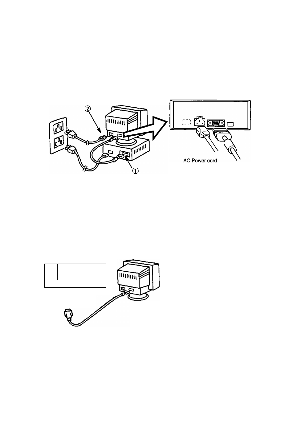
Installation
^Connecting Procedures
Turn off your computer.
Connect the signal connectors as shown below.
Turn the monitor on, then turn on the computer,
A. IBM PS/2 or compatible models
Rear view
(D Connect the supplied signal cable to the monitor’s port.
(2) Connect the AC Power cord to the monitor CE22 connector on the rear of the monitor.
(D Connect the other end of the AC Power cord to a grounded power outlet.
15'pin mini
D-Sub cable
B. Apple computer
Use a UNIMAC-82D MAC adapter.
Panasonic MAC adapter
If you need an adapter and one Is not provided by your dealer,
call 1-000 PANASYS (1-800-726-2797).
u" *
yd DDD
(D
IDI 0- “3* 9
^ MAC adapter
r—Caution:
To prevent the cable from coming loose,
the cable connectors must be securely
fastened with screws.
----------------------------
^Connection of AC Power Supply
------
Precaution:
• In order to use the display unit safely, use a power cord that is properly grounded.
• AC Power cord for the following countries are supplied in the same package.
For use in other countries, make sure the AC Power cord meets the safety standards of each country.
-----------------------------
U.S.A
.........
UL
Canada
......
CSA
-5 -
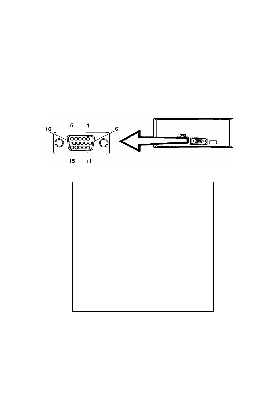
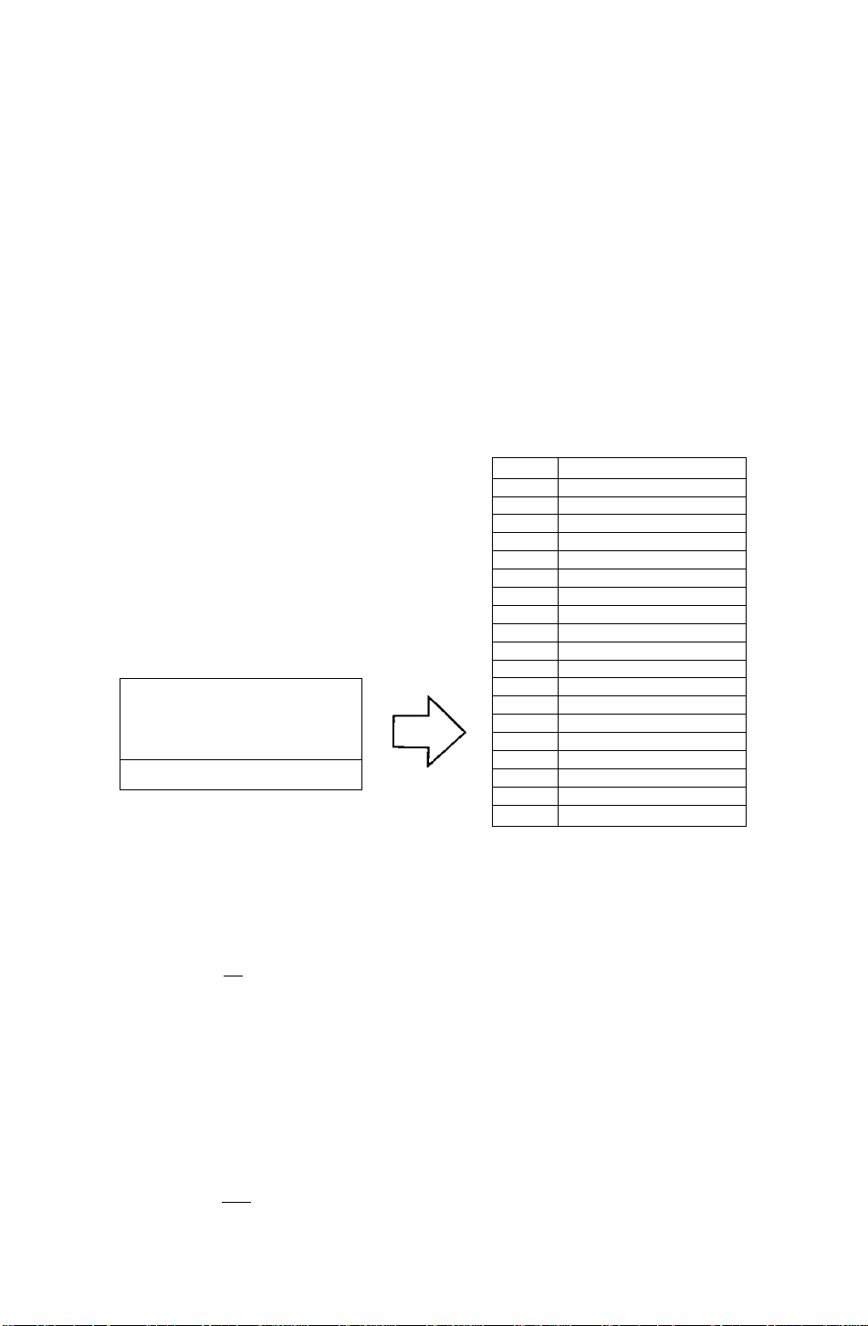
Pin Assignment
Follow the instructions below to connect the E70 to a computer.
A. Signal connector: 15-pin mini D-Sub (PS/2 or PC/AT compatible model)
Connect the signal cable to the 15-pin mini D-Sub connector on the computer.
B. Signal connector:i5-pin D-Sub (Applecomputer)
Convert a MAC 15-pin D-Sub connector to a 15-pin mini D-Sub connector using
a Panasonic MAC adapter, and connect it to the 15-pin mini D-Sub connector
on the display unit.
< REAR PANEL >
Pin assignments of 15-pin mini D-Sub connector
Pin number
1
2
3
4
5
6
7
8
9
10
11
Red video signal
Green video signal
Blue video signal
Ground
Ground*
Ground for Red video signal
Ground for Green video signal
Ground for Blue video signal
Unused
Ground
Ground
Signal name
12 SDA* (Bi-directional Data)
13
14
15
“VESA"s Display Data Channel (DDC) Standard.
Horizontal sync, signal
Vertical sync, signal
SCL* (Data Clock)
-6 -
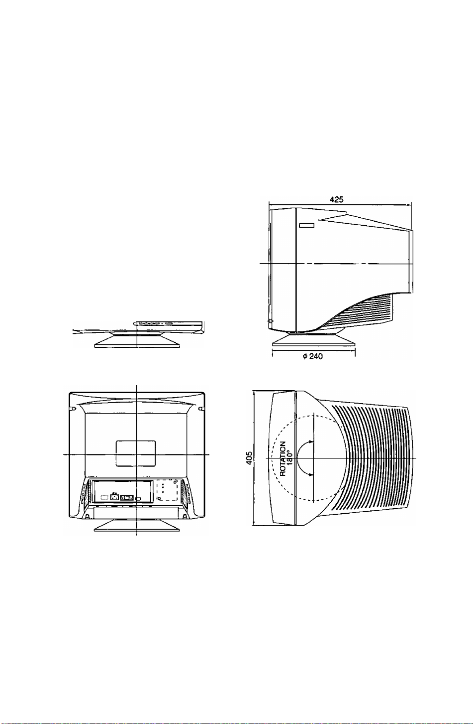
External View
Dimensions
Width : 405 mm (15.9")
Height: 404.5mm (15.9")
Depth : 425 mm (16.7")
Base diameter: <j> 240 mm( ^ 9.4")
Height without stand : 373 mm (14.7")
405
Pan/Tilt range
Up
Down
Left, right
13 degrees
4 degrees
90 degrees each
-7 -
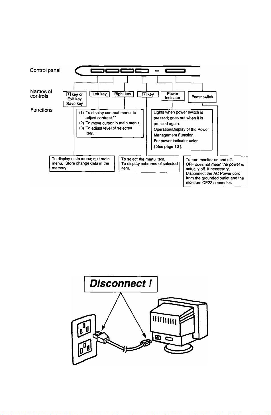
On-Screen Adjustment
[Basic operation]
m
• For a detailed description of the functions of the Q] key, left key, right key, and ¡2} key,
refer to page 9-12.
** Since contrast is the most commonly adjusted parameter, we have provided direct
access to this menu item. By pressing the 9 or B key during normal operation the
contrast menu is displayed instantly.
m ib
Note: The monitor power switch does not completely turn off the AC Power to the monitor's
circuits and piaces the monitor into a stand-by mode, which consumes about 0.1 W.
This stand-by mode gives no operation until the povrer switch is turned ON.
To totally remove power, the AC Power cord must be disconnected completely.
- 8 -
Operation
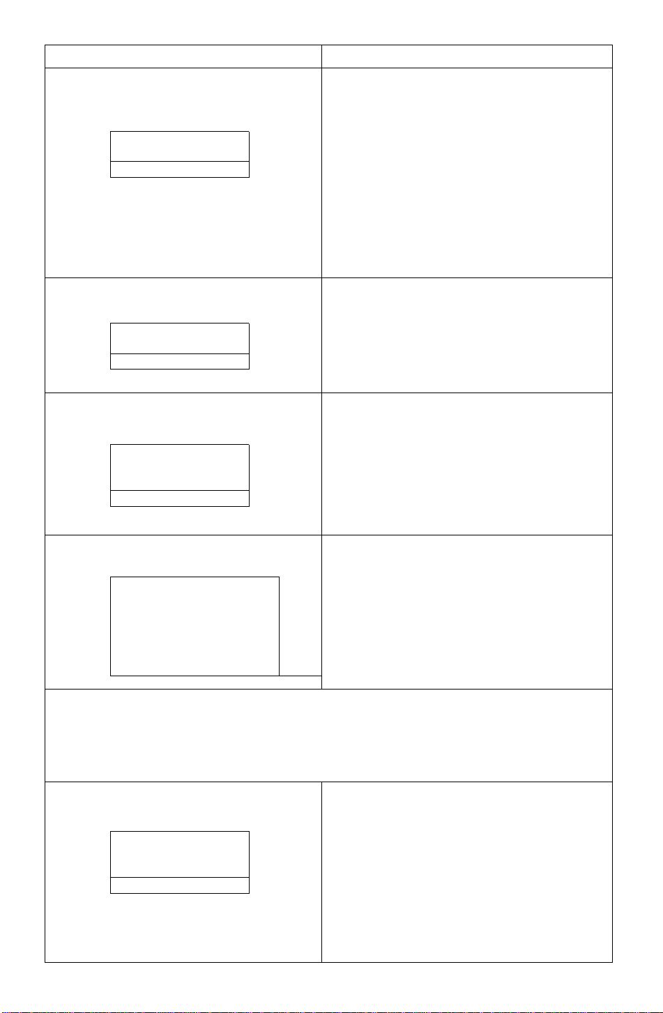
< On-Screen Display>
Monitor Self Test
Figure A
No Signal
fH —.—kHz
fV —Hz
Figure B
Error
fH 74.9kHz
fV 60.0 Hz
Menu
The adjusted items are represented by
icons.
When the D] key is pressed, the menu
screen appears.
Use the S • B keys to move the cursor
to the item to be adjusted, then press
the H] key to select the adjust menu.
1^ O
Q
?i.
ig
aaa
OSD
aoo
Coni
o
F\
trast
;€)
< Function and Operation>
This display indicates that the monitor is
operating normally. When one of the following
conditions occurs, press one of the 4 front panel
keys to call the appropriate display.
1) No Signal (The computer is not connected or
the mains power to the computer is
disconnected). See Figure A.
2) The horizontal or vertical sync. Signal are
outside of the permitted range (the value of
the horizontal sync, signal will be displayed in
red and the value of the vertical sync, signal
will be displayed in white). See Figure B.
3
E2
o
Q
ep
:©
?t
SIl
s\
s
Contrast
Brightness
Size & Pos.
H.Position
[Di
H.Size
V. Position
a
V.Size
CD
Geometry
V.Pincushion
El
Side Pin. Bal.
a
T rapezoid
Q
Parallelogram
D
Rotation
Color Temp
Recall
O ...
Video Level
Language
OSD Position
Degauss
Signal
3 Contrast adjustment
Contrast
100
3 ^
Brightness adjustment
Brightness
50
Q> ^ '
Adjust the screen contrast to match the
brightness level in the room. Press the H key to
make the image darker, the B key to make it
lighter. Pressing the H] key toggles between
brightness and contrast.
Direct operation: Even if the menu screen does
not appear, the contrast can be adjusted by
pressing the H or B key.
Contrast adjusts the white level.
* If the a and B keys are pressed at the same
time on the Contrast adjustment screen, the
maximum level (100) will be set.
Adjust the brightness to match the brightness
level in the room. Press the 3 key to make the
background darker, the B key to make it lighter.
Pressing the H] key toggles between brightness
and contrast.
Brightness adjusts the black level.
* If the a and B keys are pressed at the same
time on the Brightness adjustment screen, the
standard level (50) will be set.
-9-
< On-Screen Display>
Size & Pos.
< Function and Operation>
Press the [D key to select the HorizonU
Vertical Size adjustments.
Ш=| Horizontal Position
adjustment
H . Position
50
[Qi Э Q Ш
Horizontal Size
adjustment
H . Size
[dS Э CH
Q Vertical Position
adjustment
V. Position
50
[d S 1^ Ш - Ш
i\ Position / Horizontal Size / Vertical Position /
The horizontal position of the image can be
adjusted. Press the Э key to move it to the left,
the В key to move it to the right.
* Press the Ш key to save the adjustment.
The horizontal size of the image can be adjusted.
Press the H key to make the image smaller, the
B key to make it larger. Then press the H] key to
save the adjustment.
* Setting the image in the center of the screen will
make the size adjustment easier.
The vertical position of the image can be
adjusted. Press the a key to move it downward,
the B key to move it upward.
* Press the Ul key to save the adjustment.
m Vertical Size adjustment
Cd H S Ш : tl]
FU Geometry
Press the [H key to select the Vertical Pincushion / Side Pincushion Balance / Trapezoid
/ Parallelogram adjustments.
ГТ Vertical Pincushion adjustment
V. Pincushion
50
Oa Q/7 -[1
The vertical size of the image can be adjusted.
Press the 3 key to make the image smaller, the
B key to make it larger. Then press the D] key to
save the adjustment.
* Setting the image in the center of the screen
will make the size adjustment easier.
The image can be corrected for Pin / Barrel
distortion. Press the a key to decrease the
Pin / Barrel distortion of the image, the B key
to increase it.
-10-

< On-Screen Display> < Function and Operation>
Q Side Pincushion Balance
Side Pin. Bal.
50
UCLC^O -m
r\ Trapezoid adjustment
T ra pezo i d
50
mdcio -m
[J Parallelogram adjustment
Parallelogram
50
Oa QZ7 :
Ol Rotation (Image tilt)
adjustment
Rotation
50
The image can be corrected for barrel balance
distortion. Press the 3 key to expand to the left of
the image, the B key to expand to the right it.
The image can be corrected for trapezoidal
distortion.
Press the 3 key to make the top edge narrower,
the B key to make the bottom edge narrower.
The image can be corrected for parallelogram
distortion.
Press the 3 key to collapse the parallelogram to
the left, the B key to collapse it to the right.
Use this to adjust for tilt on the screen.
Press the 3 key to rotate the image slightly
counterclockwise, the B key to rotate the image
slightly clockwise.
*Pressing the 3 and B keys simultaneously
adjusts rotation to its factory preset level.
1*^ Color Temp
The white in the image can be adjusted.
1) Use the 3 or B keys to select 1: 9300 K + 8
Color Temp
□ 2 3 4 5
9300K+8
User Color adjustment
2) If “ 5: user’s color" is selected, “ H] ” appears
The white in the video image can be adjusted to
the user’s preferred color.
I I
R100
G 80
B 60
Note: Record the initial values of R, G and B
1) Use the [U key to select R (red) or G (green)
2) Use the 3 or B keys to adjust the color as
* Recall of the user’s color is not possible, so
here before making any adjustments:
R { Red)
G { Green )
B ( Blue )
_____________
_____________
_____________
-11 -
MPCD, 2: 7500 K, 3: 6500 K, 4: 5000 K or 5: the
user’s preferred color.
in the lower right of the On-Screen Display.
Press the front {2} key to select, the User Color
adjustment screen.
or B (blue).
desired.
make a note of the initial setting before
adjusting.
< On-Screen Display>
< Function and Operation>
O Recall
Recall
OK ?
[H; Yes NO : [D
¡Ì© Video Level
Video Level
0.7V
0.7/1 V ; [5]
7ii- Language selection
Language
FRA lagra ESP
To return to the initial settings (the settings at the
time of factory shipment).
1) When the lU key (Yes) is pressed, the settings
are recalled and the menu screen returns.
(Recall = return to settings at time of factory
shipment.)
2) When the [U key (No) is pressed, the menu
screen returns without the settings being
recalled (the settings return to what they were
immediately before the recall).
* If no operations are performed for about 30
seconds, the screen goes off without recall.
The video input signal level can be matched to
the computer being used. Either 0.7V or 1,0V
can be selected with the [U key.
Note : 0.7V is typical.
(If wrong level is selected image may be too dim
or too bright.)
The language used by the On-Screen Display
can be selected with the “H” and “B" keys from
among French, English, and Spanish.
FRA; French
ENG: English
ESP
: Spanish
llg OSD Position
It is possible to adjust the position that the OnScreen Display is to be shown in.
The On-Screen Display will rotate in a counter
clockwise direction every time the [D key is
pressed.
Degauss (Demagnetise(See Trouble Shooting Page 17 Third Symptom.))
Degaussing operation can be selected. Use this control if display color is abnormal.
After this is selected, the degaussing action takes place for approximately 6 seconds.
Key operation is not possible while demagnetization is performed.
S Signal
1024 X 768
fH 60.2kHz
fV 74.8 Hz
Resolution (1024 x 768) will only appear if the
video signal is a preset or reservation timing
(See page 15).
Signal displays the computer’s approximate
horizontal sync frequency (fH) and vertical
sync frequency (fV).
If the fH or fV are outside the specified range
then the Monitor Self Test function will auto
matically display the Signal Error menu (See
page 9, Monitor Self Test, 2).
- 12 -
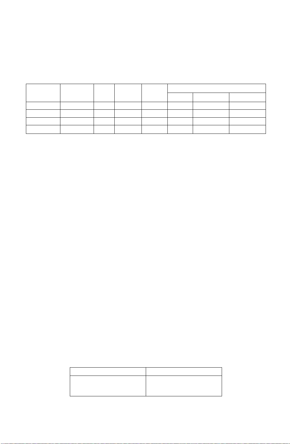
Power Management System
This monitor conforms to the VESA DPMS standard. If the Power stand-by switch is ON.
This function can reduce power consumption of the display unit.
The computer and video board being used must also conform to the VESA DPMS
standard.
* Consult the Operation Manuals for the hardware being used.
Modes change in response to input signals as indicated in the table below.
APM State Screen status
ON STATE
STAND-BY without display
SUSPEND without display
OFF STATE
with display green normal
without display
Power
Indicator
color
yellow
yellow
yellow
Power
consumption
< 15 watts
< 15 watts
< 8 watts
Return time
— ON ON
< 4 sec. OFF
< 4 sec. OFF ON
< 20 sec. OFF
video
Input signals
horizontal sync.
OFF
OFF OFF
vertical sync.
ON
ON
OFF
Caution
How to release the system from the power management function.
1) Read the Operation Manuals for the hardware you are using.
2) Press one of the [T| • a • B * CH l<eys on the front panel.
The No Signal screen appears, and the monitor side power management function is
released (only in OFF STATE).
Memories
This display has two types of memory to store the data sets that controls the on-screen
image. The first type of memory is the Preset Memory which is set by the factory. The
second type is the User Memory which is set by the user. Both memories store the
Horizontal Size, Vertical Size, Horizontal Position, Vertical Position, Vertical Pincushion,
Side Pincushion Balance, Trapezoid and Parallelogram adjustments of the displayed
image.
Preset Memory
There are 1 preset (7 reservation) timings that are set by the factory. The preset timing will automatically size
and center the image with video boards which use these timings. Please see page 14 for Timing Specifications.
User Memory
• There are 13 memory locations that allow for user timing. The image size, position, geometric distortion are
adjusted by the user. Please see page 15 and 16 for recommended timings that the display supports.
• If the User Memory is completely full, and a new set of data is saved, the oldest data set in the User Memory
will be deleted.
• The User Memory has priority over the Preset Memory.
• When the user timing is input, the Vertical, Horizontal frequencies and sync polarities of the signal are
compared with the previous data stored in memory. The input signal will be stored as a new data set if one
of its parameters is different from the previous stored one.
• The new input signal must have a frequency difference greater than that shown in the table below or a
different sync, polarity from that already stored. If the new timing data includes frequency changes greater
than those shown in the table below or sync, polarity changes, a new user memory setting will be stored. If
the frequency difference is smaller than that of the chart and the sync, polarities are the same, the existing
settings will be retained.
Horizontal frequency
Low 30 kHz ± 0.6 kHz
to
Hi 70 kHz ±1.3 kHz
Vertical frequency
Low 50 Hz ± 1.0 Hz
to
Hi 160 Hz ±3.0 Hz
Please note if the timing does not meet the display specifications, the size and position adjustment may not
appear as desired. Be sure the horizontal and vertical timing are within the monitor specification range.
See page 14 for Timing Specifications. Pages 15 and 16 for preset, reservation and recommended timing.
- 13 -

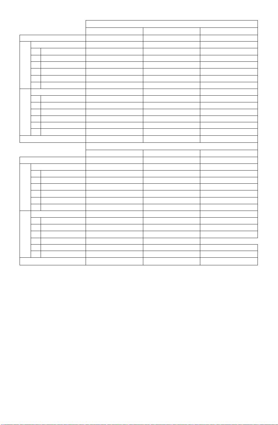
Timing Specifications
Separate Sync.
Horizontal
Vertical
H/V Composite Sync.
Horizontal
Vertical
~LJ
mnnnn
hS4-
a-a.
________
Video
0
Video
S
Video
____
Jinnnr
H D
TT
D
I Vide^o"~~l
IT
u
-----------
—§—^*-ui
“innrL
-14 -
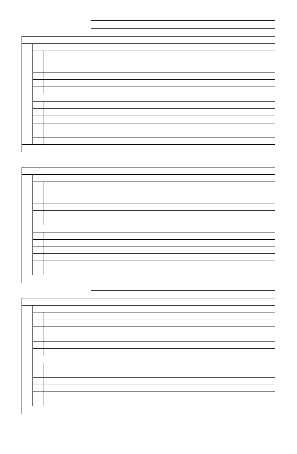
Preset timing*
VESA 1024 x 768 @75 Hz
Dot clock
fH
_
C
О
N
о
X
H-Period
A
H-Blanking
F
H-Sync width
В
H-Back porch
C
D
H-Active
H-Front porch
E
fV
P
V-Period
Л
и
CD
>
V-Btanking
U
V-Sync width
Q
V-Back porch
R
V-Active
S
V-Front porch
T
Sync polarity (HA^)
78.7500 MHz
60.023 kHz
16.660 us(l312dots)
3.657 us ( 288dots)
1.219 us ( 96dots)
2.235 us ( 176dots)
13.003 us{1024dots)
0.203 us { 16dots)
75.029 Hz
13.328 ms (BOOlines)
0.533 ms ( 32lines)
0.050 ms ( 3lines)
0.466 ms ( 28lines)
12.795 ms (768lines)
0.017 ms ( nine)
Positive/Positive
Reservation timing**
VESA 800 x 600 @75 Hz
Dot clock
fH
A
0]
I
C
О
N
о
H-Period
H-Blanking
F
В H-Sync width
H-Back porch
C
H-Active
D
H-Front porch.
E
fV
P
V-Period
_
о
ш
>
V-Blanking
u
V-Sync width
Q
V-Back porch
R
V-Active
S
V-Front porch
T
Sync polarity (H/V)
49.5000 MHz
46.875 kHz
21.333 us (1056dots)
5.172 us ( 256dots)
1.616 us ( 80dots)
3.232 us ( leOdots)
16.162 us ( SOOdots)
0.323 us ( 16dots)
75.000 Hz
13.333 ms (625lines)
0.533 ms { 25lines)
0.064 ms ( 3lines)
0.448 ms ( 21 lines)
12.800 ms (eOOlines)12.549 ms ( 624lines)
0.021 ms { nine) 0.020 ms ( nine)
Positive/Positive
Reservation timing**
МАС(16Г) 1024 X 768 @ 75Hz*"
Dot clock
fH
A
n
c
о
N
о
X
H-Period
H-Blanking
F
В
H-Sync width
H-Back porch
C
D
H-Active
E
H-Front porch
fV
P
V-Period
V-Blanking
U
и
Ф
>
V-Sync width
Q
R
V-Back porch
V-Active
S
V-Front porch
T
Sync polarity (HA/)
Note: All modes are Non-Interlaced.
* Factory Presets have exact size & centering.
** Factory Reservation have approximate size & centering.
*** Requires the use of Optionai Mac Adapter UNIMAC-82D.
80.0000 MHz
60.241 kHz
16.600 us (l328dots)
3.800 us ( 304dots)
1.200 us ( 96dots)
2.200 us ( 176dots)
12.800 us (I024dots)11.852 us(1280dots) 20.317 us ( 640dots)
0.400 us ( 32dots)
74.926 Hz
13.346 ms ( 804lines)16.661 ms (1066iines)11.886 ms (4501ines)
0.598 ms ( 36Iines) 0.656 ms ( 42lines) 2.641 ms (lOOlines)
0.050 ms ( 31ines)
0.498 ms ( 301ines) 0.594 ms ( 38lines)
12.749 ms(768lines)
0,050 ms ( 31ines)
Negative/Negativ©
Reservation timing**
VGA 640 x 480 @60 Hz
25.1750 MHz
VESA 640 x 480 @75 Hz
31.5000 MHz
31.469 kHz 37.500 kHz
31.778 us ( SOOdots)26.667 us ( 840dots)
6.356 us ( leOdots)
6.349 us ( 200dots)
3.813 us ( 96dots) 2.032 us ( 64dots)
1.907 us ( 48dots)
25.422 us ( 640dots)
0.636 us ( 16dots)
59.940 Hz
3.810 us ( 120dots)
20.317 us { 640dots)
0.508 us ( 16dots)
75.000 Hz
16.683 ms (525lines)13.333 ms ( 500lines)
1.430 msT45lines) 0.533 ms ( 20lines)
0.064 ms ( 2lines)
0.080 ms ( 3lines)
1.049 ms ( 33lines) 0.427 ms ( 16lines)
15.253 ms (480Iines)
0.318 ms ( lOlines)
Negative/Negative
MAC(16')832 X 624 @ 75 Hz™
57.2832 MHz
49.725 kHz
20.111 us (l152dots)
5.587 us ( 320dots)
1.117 us ( 64dots)
3.910 us ( 224dots)
14.524 us ( 832dots)
0.559 us ( 32dots)
74.550 Hz
13.414 ms ( 667lines)
0.865 ms ( 43lines)
0.060 ms ( 3lines)
0.784 ms ( 39lines)
12.800 ms ( 480lines)
0.027 ms ( nine)
Negative/Negative
VESA 1024 x 768 @70 Hz
75.0000 MHz
56.476 kHz
17.707 us(l328dots)
4.053 us ( 304dots)
1.813 us ( 136dots)
1.920 us ( 144dots)
13.653 us (I024dots)
0.320 us ( 24dots)
70.069 Hz
14.272 ms (806lines)
0.673 ms { 38lines)
0.106 ms { 6lines)
0.513 ms ( 29lines)
13.599 ms (768lines)
0.053 ms ( 3lines)
Negative/Negative
Negative/Negative
Recommended timing
VESA1280x1024@60Hz640 x 350 @ 84 Hz
108.0000 MHz
63.981 kHz
15.630 us (1688dots)
3.778 us ( 408dots)
1.037 us ( 112dots)
2.296 us ( 248dots)
31.5000 MHz
37.861 kHz
26.413 us ( 832dots)
6.095 us ( 192dots)
1.270 us ( 40dots)
4.063 us ( 128dots)
0.444 us ( 48dots) 0.762 us ( 24dots)
60.020 Hz 84.135 Hz
0.047 ms ( 3lines)
16.005 ms (I024lines)
0.079 ms ( 3lines)
1.638 ms ( 62lines)
9.244 ms {350lines)
0.016 ms ( nine) 0.924 ms ( 35lines)
Positive/Positive
Positive/Negative
- 15 -
Dot clock
fH 37.860 kHz
_
C
o
N
o
X
H-Period
A
F H-Blanking
H-Sync width
B
H-Back porch
C
H-Active
D
H-Front porch
E
fV
P V-Period
"5
o
Q
>
V-Blanking
U
V-Sync width
Q
R V-Back porch
S V-Active
T V-Front porch
Sync polarity (HA/)
Dot clock
fH
A H-Period
—
H-Blanking
F
C
o
N
o
X
H-Sync width
B
H-Back porch
C
D H-Active
E H-Front porch
fV
P V-Period
la
u
0
>
V-Blanking
U
V-Sync width
Q
V-Back porch
R
S V-Active
V-Front porch
T
Sync polarity (H/V)
Recommended timing
640 x 400 @ 85 Hz
31.5000 MHz
26.413 us ( 832dots)
6.095 us{ 192dots)
2.032 us ( 64dots)
3.048 us ( 96dots)
20.317 us ( 640dots)
1.016 us( 32dots)
85.080 Hz
11.754 ms (445lines)
1.189 ms ( 45lines)
0.079 ms ( 3lines)
1.083 ms( 41 lines)
10.565 ms (400lines)
0.026 ms( nine)
Negative/Positive
640x480© 85 Hz 720 x 400 @ 85 Hz
36.0000 MHz
43.269 kHz
23.111 us ( 832dots)
35.5000 MHz
37.928 kHz
26.366 us ( 936dots)
5.333 us( 192dots) 6.085 us( 216dots)
1.556 us ( 56dots)
2.222 us ( SOdots)
17.778 us( 640dots)
1.556 us { 56dots)
85.010 Hz
11.763 ms (509lines)
2.028 us( 72dots)
3.042 us ( 108dots)
20.282 us ( 720dots)
1.014 us( 36dots)
85.040 Hz
11.759 ms(446lines)
0.670 ms ( 291ines) 1.213 ms ( 46lines)
0.069 ms i 3lines) 0.079 ms ( 3lines)
0.578 ms ( 251ines)
11.093 ms (480lines)
0.023 ms ( 1line)
Negative/Negative
1.107 ms ( 42lines)
10.546 ms( 400lines)
0.026 ms( nine)
Negative/Positive
Recommended timing
800 x 600 @ 85 Hz
1024 x 768 @85 Hz 1152 x 900 © 66 Hz
56.2500 MHz 94.5000 MHz 92.9407 MHz
53.674 kHz
18.631 us(1048dots) 14.561 us(1376dots)
68.677 kHz
61.797 kHz
16.182 us(1504dots)
4.409 us{ 248dots) 3.725 us ( 352dots) 3.787 us( 352dots)
1.138 us { 64dots) 1.016 us( 96dots)
2.702 us ( 152dots) 2.201 us( 208dots)
14.222 us ( 800dots) 10.836 us(1024dots)
0.569 us { 32dots) 0.508 us ( 48dots)
1.377 us ( 128dots)
2.098 us ( 195dots)
12.395 us(1152dots)
0.312 us( 29dots)
85.060 Hz 85.000 Hz 65.950 Hz
11.756 ms (631 lines) 11.765 ms(808!ines) 15.163 ms ( 937lines)
0.578 ms ( 31 lines) 0.582 ms ( 401ines) 0.599 ms( 37lines)
0.056 ms( 3lines) 0.044 ms ( 3lines) 0.065 ms( 4lines)
0.503 ms ( 27lines) 0.524 ms ( 36lines) 0.502 ms( 31lines)
11.179 ms (600lines) 11.183 ms(768lines)
0.019 ms( nine) 0.015 ms( nine)
Positive/Positive Positive/Positive
14.564 ms ( 9001ines)
0.032 ms ( 21ines)
Composite
-16 -
 Loading...