

Page 1
ORDER NO. : PCZ1207125AE
Service Manual
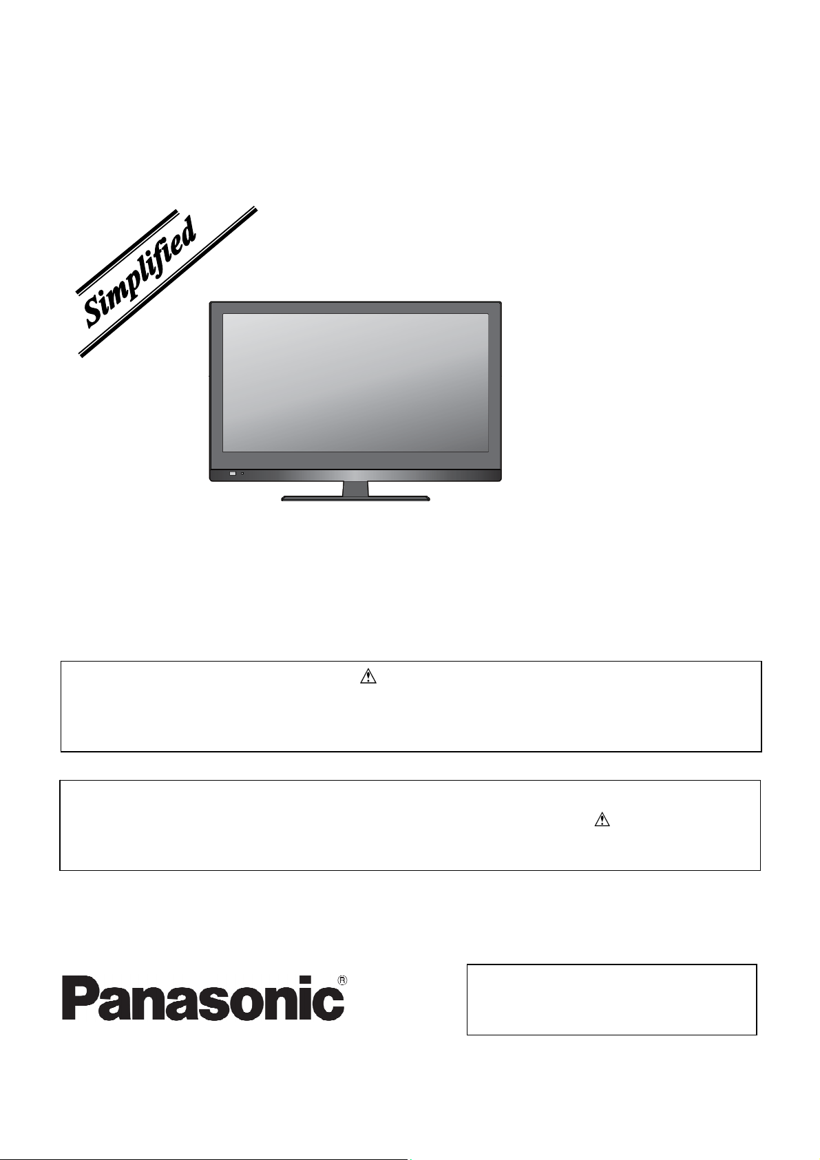
LCD TV
Model No.
TX-L24X5B
TX-L24X5E
TX-LR24X5
This service information is designed for experienced repair technicians only and is not designed for use by the general public. It does not
contain warnings or cautions to advise non-technical individuals of potential dangers in attempting to service a product. Products powered by
electricity should be serviced or repaired only by experienced professional technicians. Any attempt to service or repair the product or
products dealt with in this service information by anyone else could result in serious injury or death.
There are special components used in this equipment which are important for safety. These are marked by in the Schematic Diagrams,
Circuit Board Diagrams. Exploded Views and Replacement Parts List. It is essential that these critical parts should be replaced with
manufacture’s specified parts to prevent shock, fire or other hazards. Do not modify the original design without permission of manufacturer.
IMPORTANT SAFETY NOTICE
WARNING
© Panasonic Corporation 2012.
Unauthorized copying and distribution is a
violation of law.
Page 2

CONTENTS
2
SAFETY PRECAUTIONS........................................... 3
GENERAL GUIDE LINES........................................... 3
WARNING................................................................... 4
PREVENTION OF ELECTROSTATIC DISCHARGE
(ESD) TO ELECTROSTATICALLY SENSITIVE (ES)
DEVICES.................................................................... 4
ABOUT LEAD FREE SOLDER (PBF)......................... 5
EXPLODED VIEW AND REPLACEMENT
PARTS LIST ............................................................... 6
EXPLODED VIEW ...................................................... 6
REPLACEMENT PARTS LIST.................................... 7
Page 3
Safety Precautions
3
General Guidelines
1. When servicing, observe the original lead dress. If a short circuit is found, replace all parts which have been
overheated or damaged by the short circuit.
2. After servicing, see to it that all the protective devices such as insulation barriers, insulation papers shields are
properly installed.
3. After servicing, make the following leakage current checks to prevent the customer from being exposed to
shock hazards.
4. When conducting repairs and servicing, do not attempt to modify the equipment, its parts or its materials.
5. When wiring units (with cables, flexible cables or lead wires) are supplied as repair parts and only one wire or
some of the wires have been broken or disconnected, do not attempt to repair or re-wire the units. Replace the
entire wiring unit instead.
6. When conducting repairs and servicing, do not twist the Faston connectors but plug them straight in or unplug
them straight out.
1.1.1. Leakage Current Cold Check
1. Unplug the AC cord and connect a jumper between
the two prongs on the plug.
2. Measure the resistance value, with an ohmmeter,
between the jumpered AC plug and each exposed
metallic cabinet part on the equipment such as
screwheads, connectors, control shafts, etc. When
the exposed metallic part has a return path to the
chassis, the reading should be 100 Mohm and
over. When the exposed metal does not have a
return path to the chassis, the reading must be
.
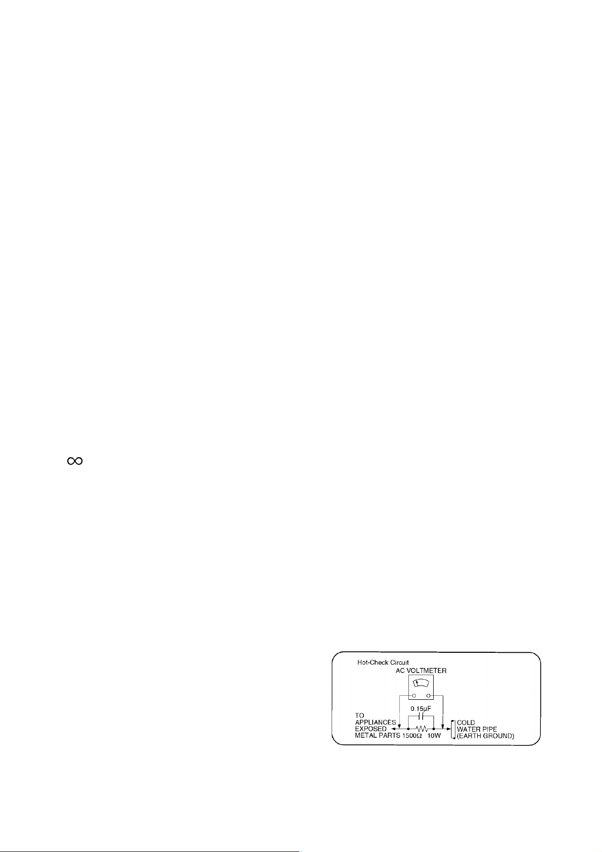
1.1.2. Leakage Current Hot Check (See Figure 1.)
1. Plug the AC cord directly into the AC outlet. Do
not use an isolation transformer for this check.
2. Connect a 1.5kohm, 10 watts resistor, in parallel
with 0.15μF capacitors, between each exposed
metallic part on the set and a good earth ground
such as a water pipe, as shown in Figure 1.
3. Use an AC voltmeter, with 1000 ohms/volt or
more sensitivity, to measure the potential
across the resistor.
4. Check each exposed metallic part, and
measure the voltage at each point.
5. Reverse the AC plug in the AC outlet and
repeat each of the above measurements.
6. The potential at any point should not exceed
0.75 volts RMS. A leakage current tester
(Simpson Model 229 or equivalent) may be
used to make the hot checks, leakage current
must not exceed 1/2 milliamp. In case a
measurement is outside of the limits specified,
there is a possibility of a shock hazard, and the
equipment should be repaired and rechecked
before it is returned to the customer.
Figure 1
Page 4

Warning
4
Prevention of Electrostatic Discharge (ESD) to Electrostatically Sensitive (ES) Devices
Some semiconductor (solid state) devices can be damaged easily by static electricity. Such components commonly
are called Electrostatically Sensitive (ES) Devices. Examples of typical ES devices are integrated circuits and some
field-effect transistors and semiconductor [chip] components. The following techniques should be used to help
reduce the incidence of component damage caused by electrostatic discharge (ESD).
1. Immediately before handling any semiconductor component or semiconductor-equipped assembly, drain off
any ESD on your body by touching a known earth ground. Alternatively, obtain and wear a commercially
available discharging ESD wrist strap, which should be removed for potential shock reasons prior to applying
power to the unit under test.
2. After removing an electrical assembly equipped with ES devices, place the assembly on a conductive surface
such as aluminum foil, to prevent electrostatic charge buildup or exposure of the assembly.
3. Use only a grounded-tip soldering iron to solder or unsolder ES devices.
4. Use only an anti-static solder removal device. Some solder removal devices not classified as [anti-static (ESD
protected)] can generate electrical charge sufficient to damage ES devices.
5. Do not use freon-propelled chemicals. These can generate electrical charges sufficient to damage ES devices.
6. Do not remove a replacement ES device from its protective package until immediately before you are ready to
install it. (Most replacement ES devices are packaged with leads electrically shorted together by conductive
foam, aluminum foil or comparable conductive material).
7. Immediately before removing the protective material from the leads of a replacement ES device, touch the
protective material to the chassis or circuit assembly into which the device will be installed.
Caution
Be sure no power is applied to the chassis or circuit, and observe all other safety precautions.
8. Minimize bodily motions when handling unpackaged replacement ES devices. (Otherwise ham less motion
such as the brushing together of your clothes fabric or the lifting of your foot from a carpeted floor can generate
static electricity (ESD) sufficient to damage an ES device).
Page 5
About lead free solder (PbF)
5
Note: Lead is listed as (Pb) in the periodic table of elements.
In the information below, Pb will refer to Lead solder, and PbF will refer to Lead Free Solder.
The Lead Free Solder used in our manufacturing process and discussed below is (Sn+Ag+Cu).
That is Tin (Sn), Silver (Ag) and Copper (Cu) although other types are available.
This model uses Pb Free solder in it’s manufacture due to environmental conservation issues. For service and repair
work, we’d suggest the use of Pb free solder as well, although Pb solder may be used.
PCBs manufactured using lead free solder will have the PbF within a leaf Symbol PbF stamped on the back of PCB.
Caution
• Pb free solder has a higher melting point than standard solder. Typically the melting point is 50 ~ 70 °F
(30~40 °C) higher. Please use a high temperature soldering iron and set it to 700 ± 20 °F (370 ± 10 °C).
• Pb free solder will tend to splash when heated too high (about 1100 °F or 600 °C).
If you must use Pb solder, please completely remove all of the Pb free solder on the pins or solder area before
applying Pb solder.If this is not practical, be sure to heat the Pb free solder until it melts, before applying Pb solder.
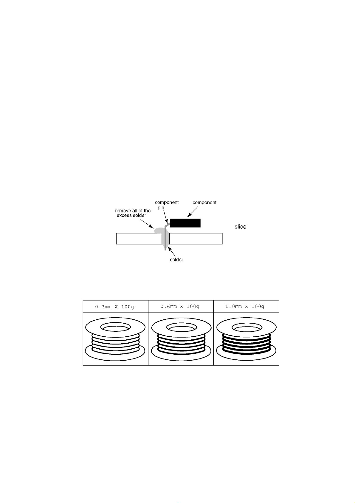
• After applying PbF solder to double layered boards, please check the component side for excess solder which
may flow onto the opposite side. (see figure below)
Suggested Pb free solder
There are several kinds of Pb free solder available for purchase. This product uses Sn+Ag+Cu (tin, silver, copper)
solder. However,Sn+Cu (tin, copper), Sn+Zn+Bi (tin, zinc, bismuth) solder can also be used.
Page 6
Exploded View and Replacement Parts List
6
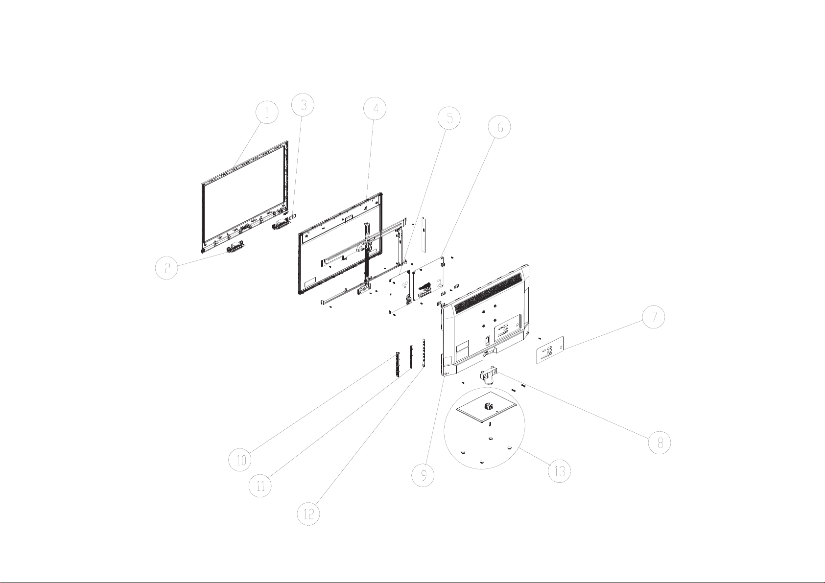
Exploded View
Page 7

Replacement Parts List
7
Components Identified by mark have special characteristics important for safety.
* When replacing any of these components, use only manufacturers specified parts.
In case of ordering these spare parts, please always add the complete Model-Type number to your order.
Important Safety Notice
Page 8
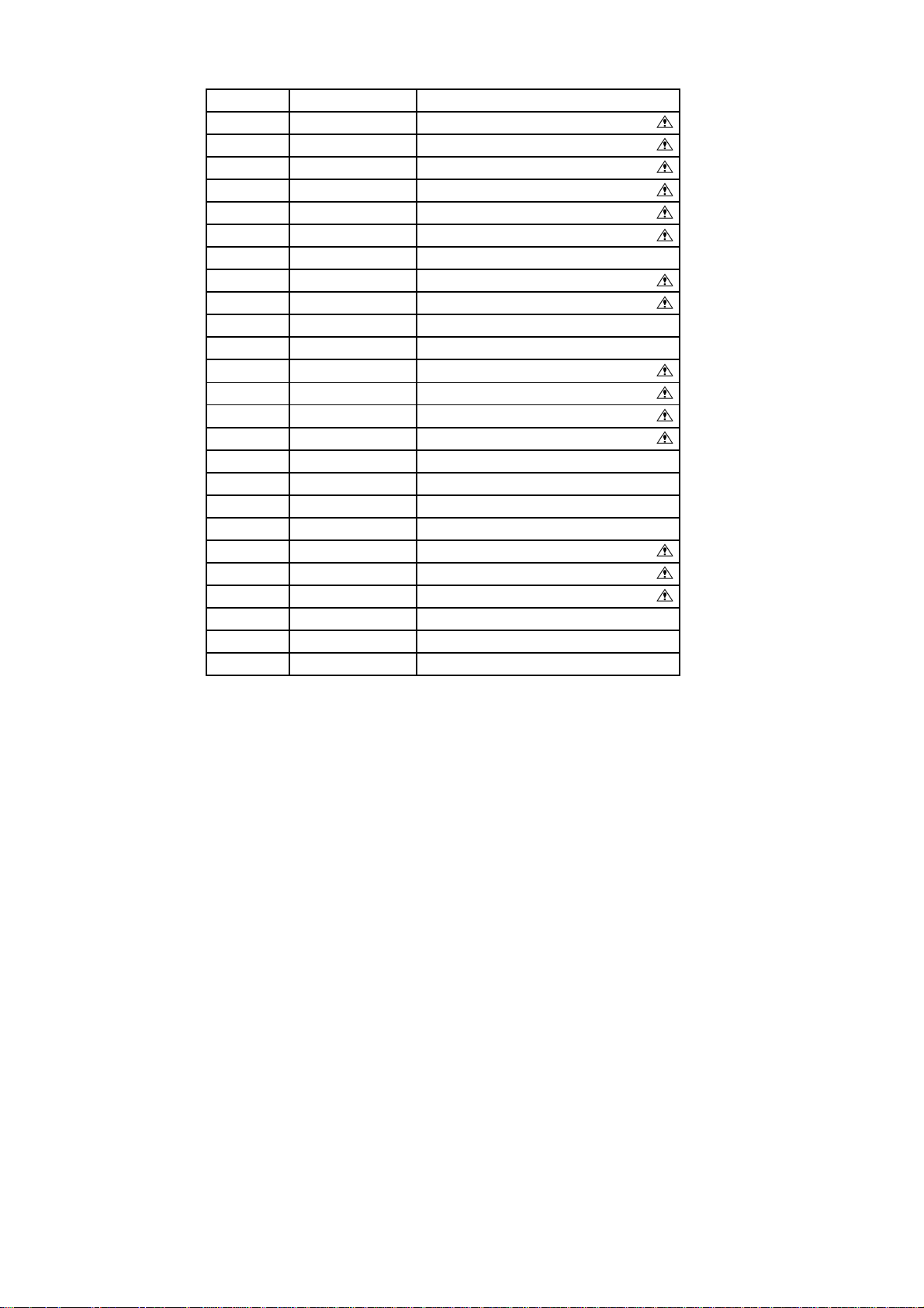
TX-L24X5B
8
Location Parts Number Description
1 TZZ00000244A BEZEL
2 TZZ00000185A SPEAKER
3 TZZ00000355A IR BOARD
4 L5EDDYY00394 LCD PANEL
5 TZZ00000396A POWER BOARD
6 TZZ00000308A MAIN BOARD
7 TZZ00000447A IO LABEL
8 TZZ00000524A STAND
9 TZZ00000245A REAR COVER
10 TZZ00000516A KEY COVER
11 TZZ00000519A KEY PAD
12 TZZ00000361A KEY BOARD
13 TZZ00000526A BASE
. TZZ00000007A REMOTE CONTROLLER
. TZZ00000187A POWER CORD
. TZZ00000207A CABLE_CN601-SPK
. TZZ00000213A CABLE_MAIN-POWER
. TZZ00000227A CABLE_CN401-001/201
. TZZ00000236A LVDS CABLE
. TZZ00000409A RATING LABEL
. TZZ00000449A MANUAL
. TZZ00000492A CARTON
. TZZ00000500A PE BAG FOR SET
. TZZ00000583A CUSHION-T
. TZZ00000584A CUSHION-B
Page 9
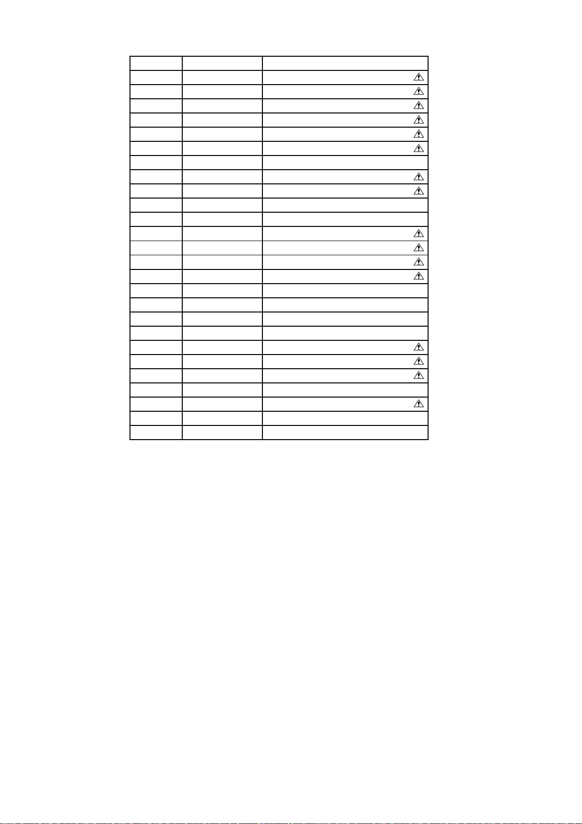
TX-L24X5E
9
Location Parts Number Description
1 TZZ00000244A BEZEL
2 TZZ00000185A SPEAKER
3 TZZ00000355A IR BOARD
4 L5EDDYY00394 LCD PANEL
5 TZZ00000396A POWER BOARD
6 TZZ00000305A MAIN BOARD
7 TZZ00000448A IO LABEL
8 TZZ00000524A STAND
9 TZZ00000245A REAR COVER
10 TZZ00000516A KEY COVER
11 TZZ00000519A KEY PAD
12 TZZ00000361A KEY BOARD
13 TZZ00000526A BASE
. TZZ00000007A REMOTE CONTROLLER
. TZZ00000177A POWER CORD
. TZZ00000207A CABLE_CN601-SPK
. TZZ00000213A CABLE_MAIN-POWER
. TZZ00000227A CABLE_CN401-001/201
. TZZ00000236A LVDS CABLE
. TZZ00000410A RATING LABEL
. TZZ00000478A QSG
. TZZ00000493A CARTON
. TZZ00000500A PE BAG FOR SET
. TZZ00000509A CD MANUAL
. TZZ00000583A CUSHION-T
. TZZ00000584A CUSHION-B
Page 10
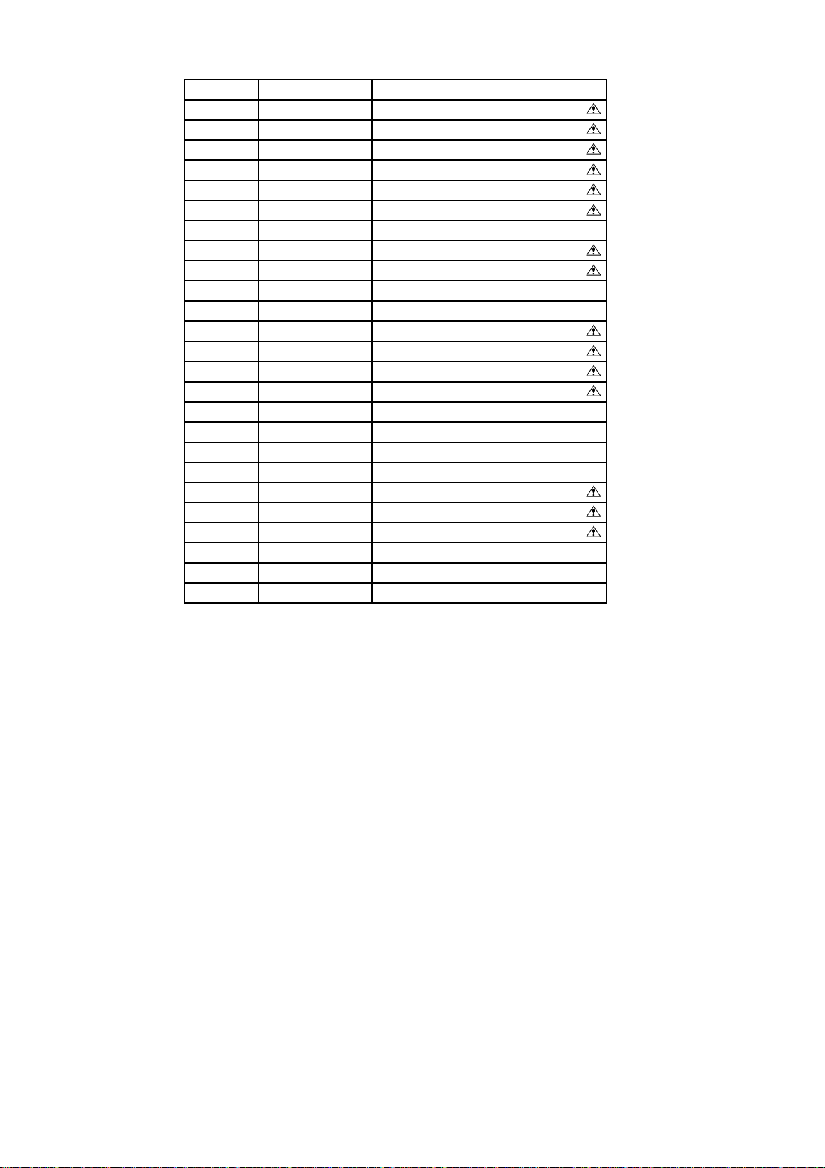
TX-LR24X5
10
Location Parts Number Description
1 TZZ00000244A BEZEL
2 TZZ00000185A SPEAKER
3 TZZ00000355A IR BOARD
4 L5EDDYY00394 LCD PANEL
5 TZZ00000396A POWER BOARD
6 TZZ00000310A MAIN BOARD
7 TZZ00000448A IO LABEL
8 TZZ00000524A STAND
9 TZZ00000245A REAR COVER
10 TZZ00000516A KEY COVER
11 TZZ00000519A KEY PAD
12 TZZ00000361A KEY BOARD
13 TZZ00000526A BASE
. TZZ00000007A REMOTE CONTROLLER
. TZZ00000177A POWER CORD
. TZZ00000207A CABLE_CN601-SPK
. TZZ00000213A CABLE_MAIN-POWER
. TZZ00000227A CABLE_CN401-001/201
. TZZ00000236A LVDS CABLE
. TZZ00000411A RATING LABEL
. TZZ00000450A MANUAL
. TZZ00000494A CARTON
. TZZ00000500A PE BAG FOR SET
. TZZ00000583A CUSHION-T
. TZZ00000584A CUSHION-B
 Loading...