

Page 1
Stereo Colour Television
With TELETEXT
Operating Instructions
TX-76PW10A
TX-76PW05A
Please read these operating instructions completely before operating this
[tau]
FLA
DIGI AL
Dolby, Pro Logic and the symbol are trademarks of Dolby Laboratories.
Manufactured under licence from Dolby Laboratories.
Manufactured under licence from Digital Theatre Systems, Inc. US Pat. No. 5,451,942 and other world-wide patents
issued and pending. “DTS” and “DTS Digital Surround” are trademarks of Digital Theatre Systems, Inc. Copyright
1996 Digital Theatre Systems, Inc. All Rights Reserved.
set and retain the booklet for future reference.
TQB4A0145
Page 2

Dear Panasonic Customer,
Welcome to the Panasonic family. We hope that you will have many years of enjoyment from your
new Colour Television.
Please retain your proof of purchase along with these operating instructions. Space has been
made available on the back page of this instruction book for recording the Serial Number. The Serial
Number can be found on the back cover of the set and on the packing carton.
Important Information
Programme Location Numbers
This television comes to you “factory tuned” to all the major capital city broadcast stations. Adjustments to
the tuning should not be necessary. However, if you have to make adjustments, please read these instructions carefully first. Throughout this booklet “Programme Location Numbers” are referred to. These are
memory locations into which you can tune television broadcast stations. Any television station can be
tuned into any Programme Location Number.
Picture Quality
All televisions are affected by Magnetic Interference.
Magnetic interference may come from such things as
unshielded motors, moving the TV while it is switched
ON, turning off a vacuum cleaner too close to the TV,
lightning strikes nearby or many other things.
The interference shows up as coloured patches which
appear while the TV is switched ON.
A typical result may look like the picture shown.
• Your Panasonic Television is designed to overcome this with the inclusion of a demagnetising (de-
gaussing) function.
• To activate this feature, simply switch your Television OFF with the Power On/Off Switch (not with
the remote control) for 30 minutes and then switch it back ON.
• If the television is to be left unattended for extended periods (several days or more), turn the power
off to the unit. DO NOT leave in Standby mode.
• This will ensure that you enjoy the picture clarity as it was meant to be.
Refer to page 33 for operating instructions for the GEOMAGNETIC feature.
2
Page 3
Getting Started
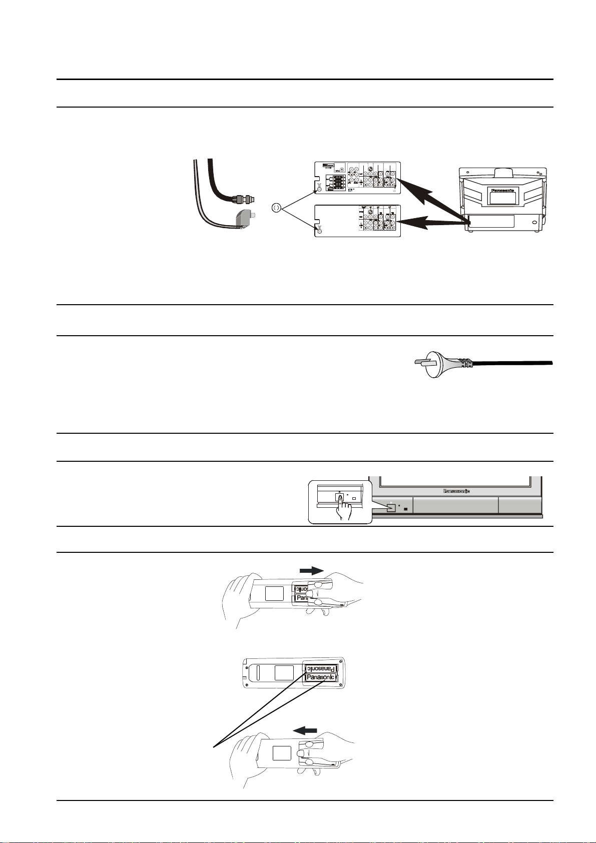
To Antenna
TX-76PW05A
Balun
Connect the Aerial
The RF (Aerial) Input impedance of this television is 75Ω. If your aerial lead is 300Ω ribbon (two wires
separated by a flat plastic sheet) you will require a 300Ω/75Ω Balun (not supplied) in order to connect your
aerial to the television.
75Ω
Cable
Ω
300
Cable
RF
Input
ΩΩ
Note:
For your safety any external aerial should be installed by a reputable qualified installer and should comply
with Australian Standard AS1417.1.
In New Zealand the installation should comply with International Standard IEC597-1.1.
300 / 75
TX-76PW10A
Connect the Power Plug
The televisions are designed for the Australian Standard Mains Voltage of
240V 50Hz and the New Zealand Standard Mains Voltage of 230V 50Hz.
NOTE:
If the television is not going to be used for an extended period, remove the power plug from the wall outlet.
Turn on the Television
Push the Power Switch to turn the television ON.
Sit back and enjoy your new Panasonic television.
Battery Installation and Replacement
Place your thumb on the battery
cover triangle. Apply a slight
downward pressure with the
thumb and slide the cover back.
This allows the cover to be
removed.
Insert the batteries ensuring the
correct polarity. The polarity is
identified by the “ + “ symbol on
the battery and the “ + “ and “ - “
symbols on the battery
compartment. The springs inside
the battery compartment connect
to the negative terminal of the
battery.
Two “AA” size batteries
Fit the battery cover and slide it
forward until it “clicks” into place.
Battery Precautions
• Do Not use rechargeable batteries.
Differences in size and performance
may cause incorrect operation.
• Do Not mix battery types (Alkaline
with zinc-carbon etc.)
• Do Not mix old and new batteries.
Replace both batteries at the same
time.
• Do Not attempt to recharge
batteries.
• Do Not short circuit batteries.
• Do Not disassemble batteries.
• Do Not heat or burn batteries.
3
Page 4
CONTENTS
Control Panel Buttons....................................................................................................................................6
Remote Control Television Buttons .............................................................................................................6
STR..............................................................................................................................................7
F................................................................................................................................................... 7
-/\/.................................................................................................................................................7
+//\................................................................................................................................................7
TV/AV...........................................................................................................................................7
STANDBY.................................................................................................................................... 8
PICTURE .....................................................................................................................................8
SOUND ........................................................................................................................................8
SET UP ........................................................................................................................................8
STEREO / MONO / BILINGUAL* ................................................................................................8
100Hz / PROGRE........................................................................................................................8
SURROUND ................................................................................................................................8
ASPECT.......................................................................................................................................8
MULTI PIP ...................................................................................................................................8
RECALL .......................................................................................................................................9
N NORMALISATION .......................................................................................................................9
STR..............................................................................................................................................9
? HELP..........................................................................................................................................10
MUTE.........................................................................................................................................10
PROGRAMME NUMBER DOWN AND UP ...............................................................................10
VOLUME DOWN AND UP.........................................................................................................10
TV / AV ...................................................................................................................................... 10
COLOURED BUTTONS ............................................................................................................10
STILL .........................................................................................................................................10
CH SEARCH..............................................................................................................................11
0 ~ 9 DIRECT PROGRAMME NUMBER SELECTION ......................................................................11
- / - - TWO DIGIT PROGRAMME NUMBER SELECTION ................................................................11
Using the On Screen Displays ................................................................................................................... 12
Picture Menu Operation .......................................................................................................................13 ~ 14
MENU ........................................................................................................................................13
CONTRAST, BRIGHTNESS, COLOUR, SHARPNESS, NTSC-TINT ......................................13
COLOUR TEMPERATURE ....................................................................................................... 14
PICTURE NOISE REDUCTION ................................................................................................14
ARTIFICIAL INTELLIGENCE ....................................................................................................14
SCAN MODE ............................................................................................................................. 14
Sound Menu Operation ........................................................................................................................15 ~ 16
MENU ........................................................................................................................................15
VOLUME, BASS, TREBLE, BALANCE, HEADPHONE VOL, SUBHEADPHONE ...................15
SUBWOOFER ...........................................................................................................................16
SURROUND MENU...................................................................................................................16
Surround Sound Operation .................................................................................................................17 ~ 19
Set Up Menu Operation........................................................................................................................20 ~ 21
TELETEXT.................................................................................................................................20
OFF TIMER ...............................................................................................................................20
FLICKER REDUCTION .............................................................................................................20
STROBE ....................................................................................................................................20
CH COLOUR SET .....................................................................................................................20
VCR / GAME..............................................................................................................................21
TEXT SELECT...........................................................................................................................21
CHILD LOCK .............................................................................................................................21
COLOUR SYSTEM ....................................................................................................................21
TUNING MENU..........................................................................................................................21
GEOMAGNETIC........................................................................................................................21
LANGUAGE............................................................................................................................... 21
4
Page 5

CONTENTS
Aspect Control .............................................................................................................................................. 22
Teletext Operation ................................................................................................................................23 ~ 26
F.P. (Favourite Page) ................................................................................................................24
Set Up ........................................................................................................................................24
TV/TEXT ....................................................................................................................................24
STR (Store)................................................................................................................................24
PAGE NUMBER UP & DOWN BUTTONS................................................................................24
SUB-PAGE NUMBER UP & DOWN BUTTONS ....................................................................... 24
COLOUR CODED BUTTONS ...................................................................................................24
INDEX ........................................................................................................................................24
HOLD .........................................................................................................................................24
0 ~ 9 Page Number Buttons................................................................................................................24
REVEAL.....................................................................................................................................25
F/T/B (Full / Top / Bottom).........................................................................................................25
Display Cancel ........................................................................................................................... 25
TIME TEXT ................................................................................................................................25
Tuning Menu .........................................................................................................................................26 ~ 32
SYS Select.................................................................................................................................27
Auto Tune ..................................................................................................................................28
Manual Tune ..............................................................................................................................29
Tuning the Television to a VCR .................................................................................................29
Fine Tuning ................................................................................................................................30
Skip ............................................................................................................................................30
Geomagnetic Correction..............................................................................................................................31
Remote Control VCR/LD/DVD Operation ................................................................................................... 32
Remote Control VCR/LD/DVD Buttons...........................................................................................................33
REWIND / REVIEW ................................................................................................................... 33
STOP .........................................................................................................................................33
POWER BUTTON .....................................................................................................................33
RECORD ...................................................................................................................................33
PAUSE.......................................................................................................................................33
PLAY..........................................................................................................................................33
FAST FORWARD / CUE ...........................................................................................................33
VCR/LD/DVD .............................................................................................................................33
PROGRAMME NUMBER UP & DOWN / PROGRAMME SKIP ...............................................33
STILL ADVANCE DISC SIDE B SELECTION...........................................................................33
DISC SIDE A SELECTION........................................................................................................33
Manufacturers’ Code Settings......................................................................................................................... 34
Connecting Equipment to the TV ........................................................................................................35 ~ 43
Front Panel Connections ................................................................................................................................ 35
Headphone Connections............................................................................................................35
Rear Panel Connections ................................................................................................................................. 36
Monitor Out ................................................................................................................................ 36
Connecting a Standard VCR to the AV Input.............................................................................37
Connecting S-Video Equipment to the AV Input........................................................................37
Connecting DVD Equipment to the AV Input .............................................................................37
Audio Out ...................................................................................................................................38
Digital Audio In........................................................................................................................... 38
External Speakers......................................................................................................................39
Customer Information ..........................................................................................................................40 ~ 44
Warnings & Cautions ......................................................................................................................................40
Cleaning, Locating and Caring for the Television ...........................................................................................41
Caring for the Remote Control ........................................................................................................................41
Troubleshooting ..............................................................................................................................................42
Specifications ..................................................................................................................................................43
Customer’s Record ........................................................................................................................... Back Page
5
Page 6
Control Panel Buttons
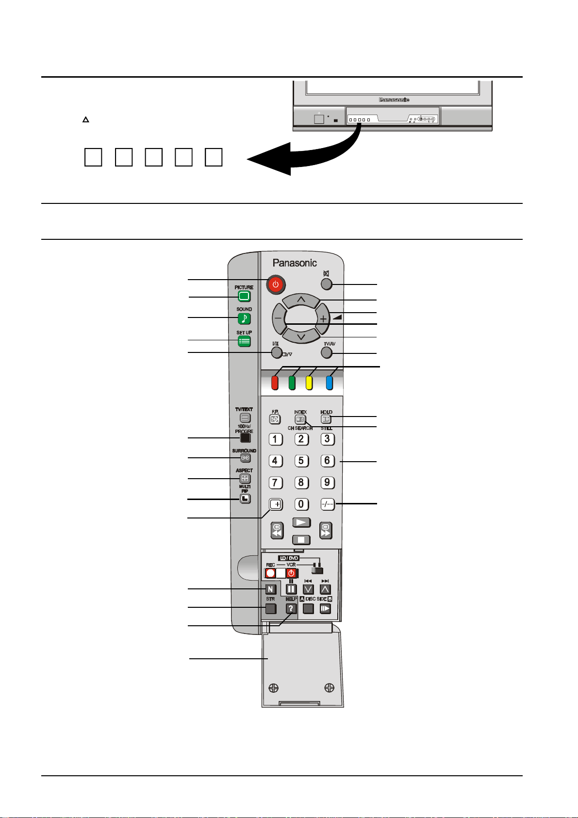
Open the control panel door to gain access to the
Television Controls Push the door at the point
marked to open.
Push again to close.
STR F -/\/ +//\ TV/AV
Remote Control Buttons
L/MONO R
AV3
IN
S-VIDEO VIDEOSTR F -/\/ +//\ TV/AV
AUDIOMain Sub.
Stand By
Picture
Sound
Set Up
Stereo / Mono / *Bilingual
100Hz / Progressive Scan
Surround
Aspect
Multi Picture in Picture #
Recall
Mute
Programme Number Up
Volume Up
Volume Down
Programme Number Down
TV / AV / RGB
Coloured Buttons. Used for
Aspect Functions, AV Selection
Teletext Functions
Still
Channel Search #
Direct Programme Numbers
Two Digit Programme
Numbers
Normalisation
Store
Help
Door
For details of TELETEXT Operation remote control operation, please refer to page 23.
For details of VCR, LD player and DVD player remote control operation, please refer to page 32.
* Bilingual broadcasting is not currently available in Australia or New Zealand.
# Multi Picture In Picture button and “CH SEARCH” are not on the remote control used for the TX-76PW05A.
6
Page 7
Television Control Panel Buttons
BUTTON WHAT IT DOES
STR
This button is used to store tuning information and other function settings. It is
STR
F
also used to start the menu demonstration.
F
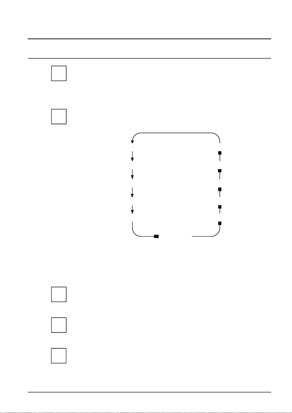
The F button is used to select the on screen display functions. Press the button to
select the following functions sequentially.
VOLUME GEOMAGNETIC
CONTRAST TUNING MODE
-/\/
+//\
BRIGHTNESS BALANCE
COLOUR TREBLE
SHARPNESS BASS
NTSC-TINT
Notes:
NTSC-TINT: Only displayed when receiving NTSC signals.
TUNING MODE: Not displayed when in AV mode.
BALANCE: Not displayed when SURROUND is on.
- / \/
This button is used to select the next lower programme number.
It is also used with the F button to adjust function settings.
+ / /\
This button is used to select the next higher programme number.
It is also used with the F button to adjust function settings.
TV / AV
This button is used to switch between the TV mode and the four AV modes.
TV/AV
Please refer to drawing on Page 6 for location of Remote Control Buttons.
7
Page 8
Remote Control Television Operation
BUTTON WHAT IT DOES
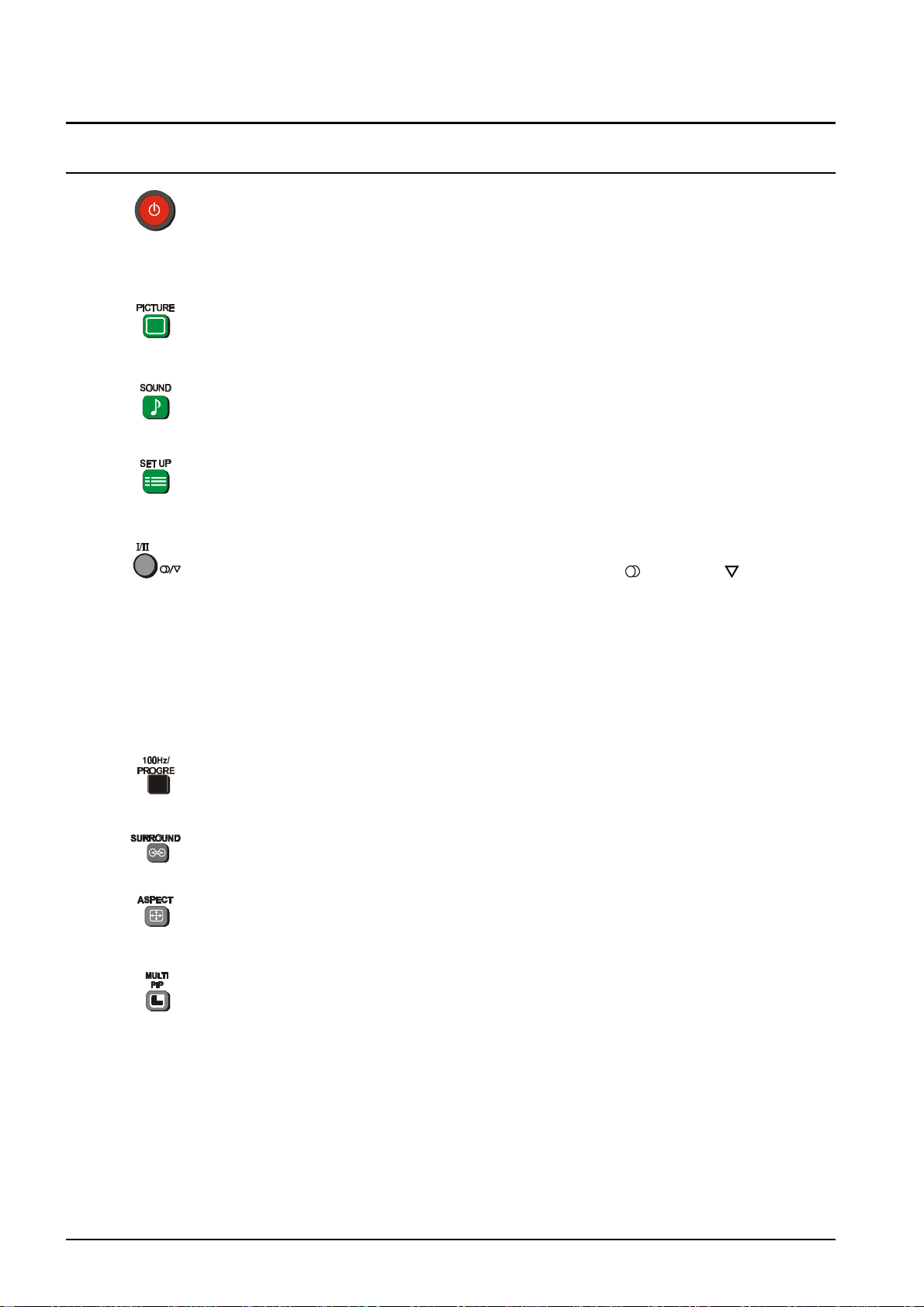
STANDBY
The remote control button is used to turn the television into Standby mode. When
the television is in Stand-By it is possible to turn it back on by pressing this remote
control Power Button, the Programme Number UP or DOWN Button (front panel
or remote control) or any of the direct Programme Number Buttons.
PICTURE
This button is used to select the picture menu. Please refer to page 13 for detailed
operating instructions.
SOUND
This button is used to select the sound menu. Please refer to page 15 for detailed
operating instructions.
SET UP
This button is used to select the set up menu. Please refer to page 21 for detailed
operating instructions.
STEREO / MONO
Pushing the button changes the mode from Stereo ( ) to Mono ( ) and back
again. Normally the television will detect whether the broadcast signal is Mono or
Stereo and will set the mode accordingly. If the Stereo signal is weak or if the
receiving conditions are not the best, it is recommended that the Mono mode be
manually selected.
BILINGUAL *
This system allows two languages to be transmitted on one signal. Switching
between the Main ( I ) and Sub ( II ) positions selects the desired language.
* Note: Bilingual sound is not currently available in Australia or New Zealand.
100Hz / PROGRE
This button allows you to change the Picture refresh setting between AUTO,
100Hz MODE and PROGRESSIVE. Please refer to SCAN MODE on page 14.
SURROUND
This button switches the SURROUND on and off.
ASPECT
This button is used to move through the different aspect options of AUTO, 4:3,
ZOOM, S-ZOOM, 16:9, 14:9 and JUST. Please refer to page 22.
MULTI PIP (TX-76PW10A only)
Pressing this button will access the Picture in Picture options. If the 4:3 aspect
ratio is selected you can choose between normal, Picture And Picture and
Picture Out Of Picture. All other aspect ratio settings let you choose between
normal, Picture And Picture and Picture In Picture.
Notes:
The MULTI PIP picture can be another television channel or an AV input.
While the On Screen Display is shown the sub-picture can be changed using the
0 ~ 9 and the “- / - -” buttons, as shown on page 11.
When the On Screen Display disappears the main picture can be changed using
the 0 ~ 9 and the “- / - -” buttons, as shown on page 11.
MULTI PIP is not available on the TX-76PW05A.
Please refer to drawing on Page 6 for location of Remote Control Buttons.
8
Page 9

Remote Control Television Operation
BUTTON WHAT IT DOES
Picture In Picture Mode
Allows two pictures to be viewed at the same
time. Pressing the Red button will change the
position of the small picture. The Yellow button
swaps between the two pictures. The Blue
button removes the option bar.
Picture Out Of Picture Mode
Allows two pictures to be viewed at the same
time. The pictures will be shown side by side.
The Yellow button swaps between the two
pictures. The Blue button removes the option
bar.
Picture And Picture Mode
Allows two pictures to be viewed at the same
time. The pictures will be shown side by side.
Both pictures will be the same size.
The Yellow button swaps between the two
pictures. The Blue button removes the option
bar.
2 4
LOCATE CHANGE EXIT
2 4
CHANGE EXIT
2 4
CHANGE EXIT
RECALL
Pressing this button will display all current active functions. The functions that can
be displayed include AV Number, Programme Number, Sound Option, Picture
Option, Stereo or Mono and Off-Timer setting. Pressing the button again cancels
the recall function and removes the text being displayed on the screen.
If the button is not pressed within about 2 seconds it automatically switches to
display the Programme Number or the AV Number and the Off-Timer setting.
Pressing the button again cancels the recall function and removes the text being
displayed on the screen.
NORMALISATION
The Normalisation Button is used to reset the television to factory set levels.
Colour, Sharpness, Contrast, Brightness, Treble, Bass and Balance will be reset.
The button will only operate if the menu is displayed on the screen.
STR
The STR (Store) button is used with a number of features to store settings after
adjustments have been made or options have been set. It is also used in
TELETEXT and tuning functions.
HELP
Pressing this button displays on screen instructions on how to adjust various
settings and how to connect external equipment. Press the HELP button and
select one of the options. Please refer to page 12.
Please refer to drawing on Page 6 for location of Remote Control Buttons.
9
Page 10
Remote Control Television Operation
BUTTON WHAT IT DOES
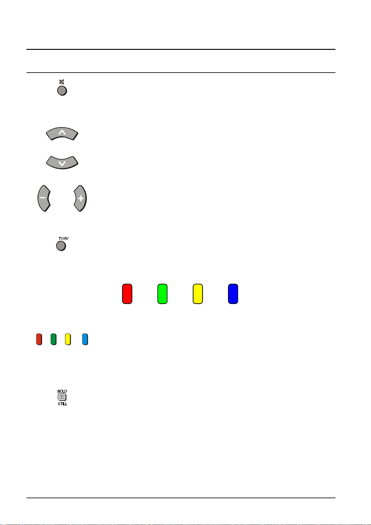
SOUND MUTE
Pressing this button reduces the sound from the television to nil. Pressing the
button again returns the sound to the original setting. Pressing the Volume
Up ( + ) or Down ( - ) will also restore the volume level setting.
PROGRAMME NUMBER UP & DOWN
Pressing this button selects the next higher ( /\ ) or lower ( \/ ) Programme
Number in sequence. Programme Numbers which have been “Skipped” (See
page 32) will be bypassed when this button is used.
VOLUME DOWN & UP
This button is used to increase ( + ) or decrease ( - ) the volume output level
from the television.
TV / AV
Pressing the TV/AV Button will cycle between TV, the current AV Input, RGB and
back to TV. While the AV indicator is still on screen the different AV inputs can
be selected using the coloured buttons.
RED GREEN YELLOW BLUE
AV1 AV2 AV3 AV4
COLOURED BUTTONS
These buttons are used for:
- selecting different aspect ratios
- selecting different AV inputs
- teletext functions
Still
Press this button to freeze the picture on the screen. Press it again to return to
normal viewing.
10
Please refer to drawing on Page 6 for location of Remote Control Buttons.
Page 11
Remote Control Television Operation
BUTTON WHAT IT DOES
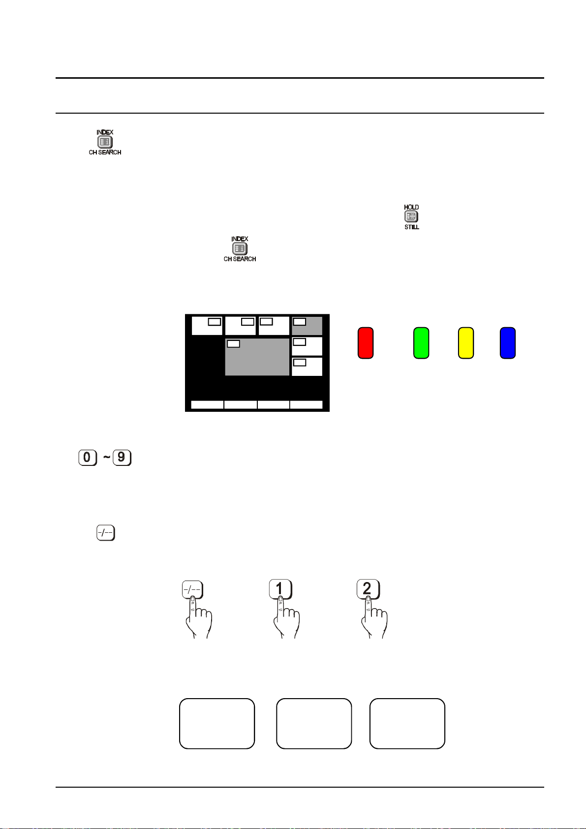
CHANNEL SEARCH (TX-76PW10A only)
This option is used to show freeze frames of the programmes being broadcast on
all the stored channels. The images are displayed clockwise around the edge of
the screen starting from the top left corner. The current programme is displayed
in the centre of the screen. When the display gets back to the top left corner it
will overwrite the first picture with the next one in series.
The display will continue to change until either the button is pressed to
pause or is pressed to exit the feature.
The Red button is used to select each programme in turn. The green button is
used to swap the main display between the current programme and the one
selected by the red button. The Blue button returns to normal viewing.
3
21
4
SELECT OK EXIT
4
5
6
RED GREEN YELLOW BLUE
SELECT OK EXIT
DIRECT PROGRAMME NUMBER SELECTION
Single Digit Programme Numbers (0 to 9) can be accessed directly by pressing
the corresponding number on the Remote Control Transmitter.
TWO DIGIT PROGRAMME NUMBER SELECTION
To directly access Programme Numbers 10 to 99, press the “- / - -” Button followed by the two digits required. For example, to select Programme Number 12:
The On-Screen display will be as shown:
_ _ 1_ 12
Please refer to drawing on Page 6 for location of Remote Control Buttons.
11
Page 12
Using The On Screen Displays
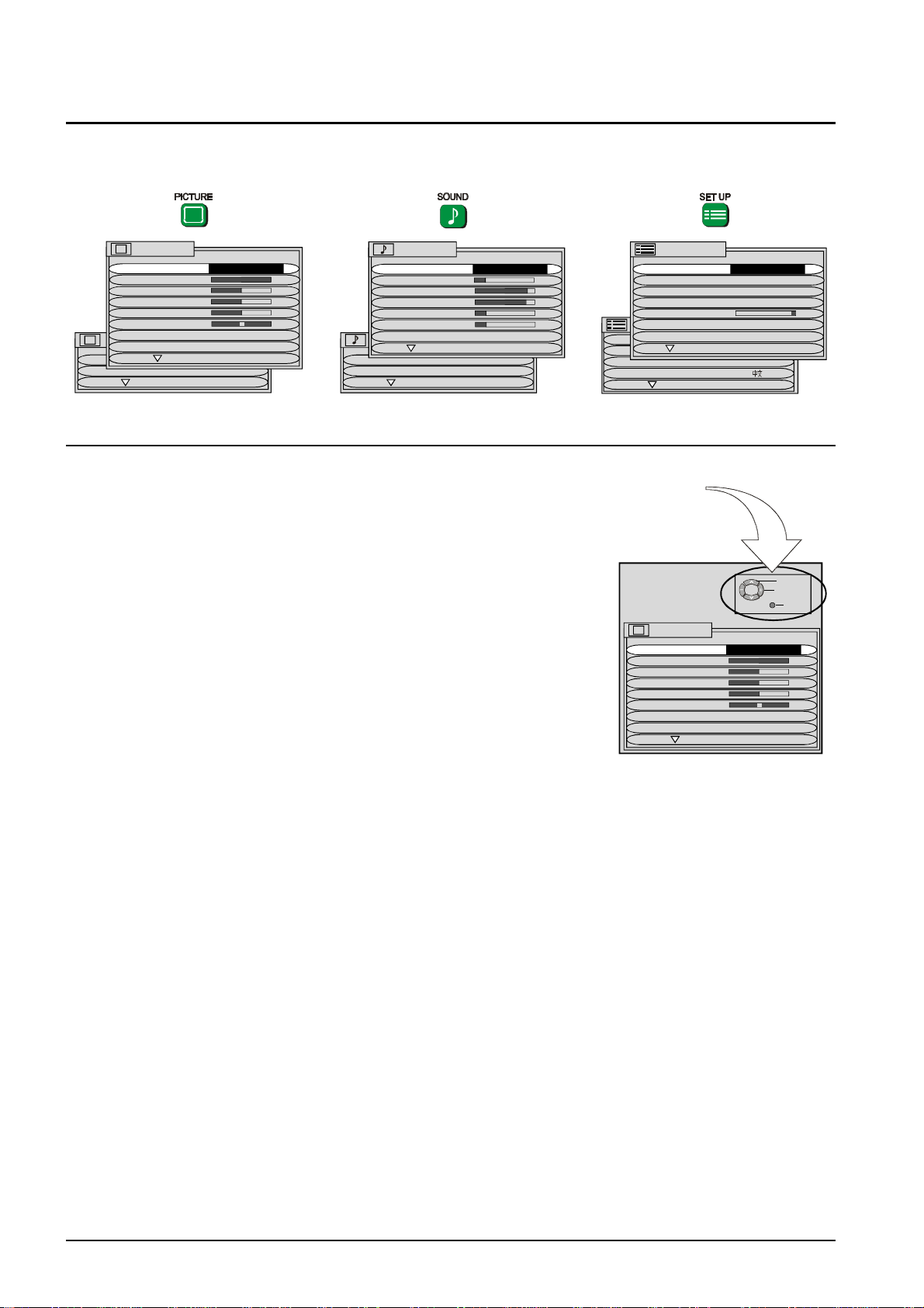
Many features available on this TV can be accessed via the On Screen Display menu
system. Use the remote control to access and adjust features as required.
PICTURE
MENU DYNAMIC
CONTRAST
BRIGHTNESS
COLOUR
SHARPNESS
NTSC-TINT
C. TEMP STANDARD
PICTURE
P-NR AUTO
AI ON
SCAN MODE AUTO
SOUND
MENU DYNAMIC
VOLUME
BASS
TREBLE
HEADPHONE VOL
SUBHEADPHONE
SUB WOOFER NORMAL
SOUND
DIGITAL AUDIO
SURROUND MENU
An on screen help box is displayed whenever a menu is displayed on
the TV. This help box indicates which keys on the remote control are
used to navigate the menu shown. See above for descriptions of button
functions.
Note:
The help box is not shown in the menu pictures in this manual due to
space limitations.
SET UP MENU
TELETEXT TOP
OFF TIMER OFF
FLICKER REDUC OFF
STROBE
CH COLOUR SET
SET UP MENU
VCR/GAME OFF
TEXT SELECT ENGLISH
CHILD LOCK OFF
TUNING MENU
GEOMAGNETIC
LANGUAGE ENGLISH
ON SCREEN HELP
Instruction box
PICTURE
MENU DYNAMIC
CONTRAST
BRIGHTNESS
COLOUR
SHARPNESS
NTSC-TINT
C. TEMP STANDARD
P-NR AUTO
SELECT
CHANGE
TV/AV EXIT
12
Page 13
Picture Menu Operation
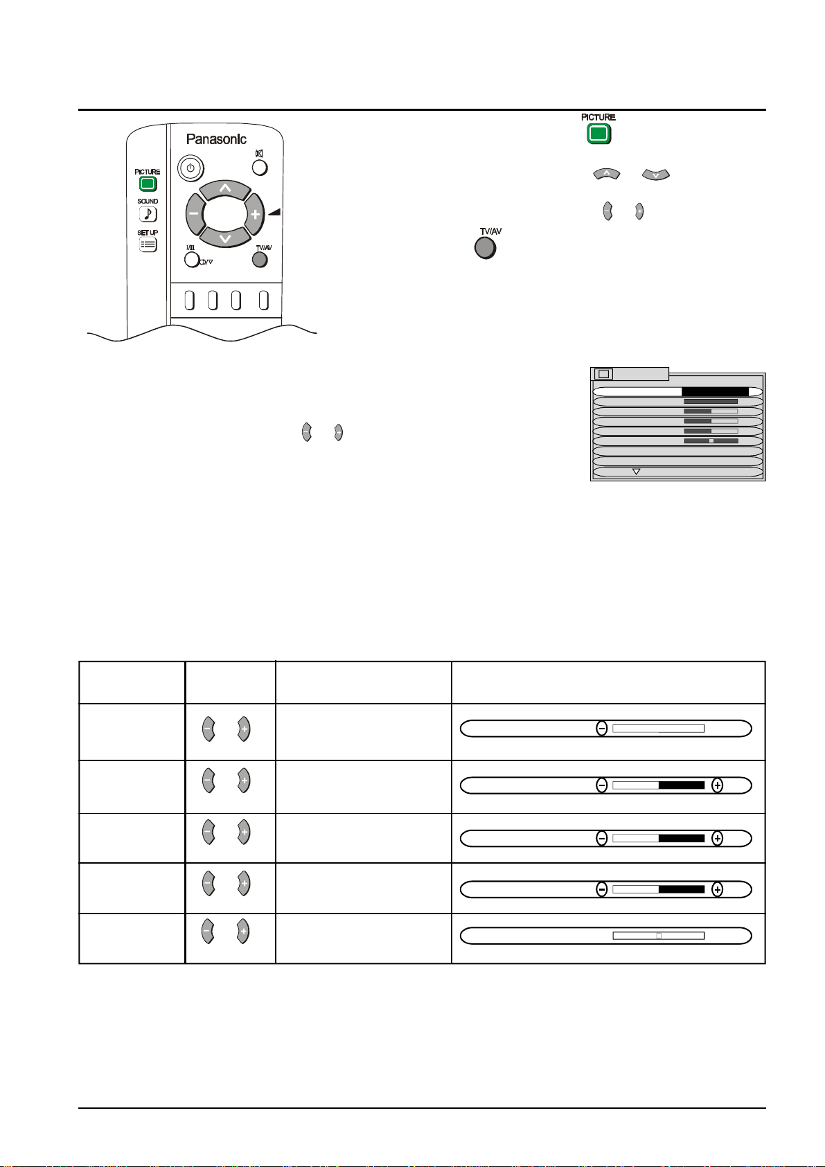
1 Push the PICTURE button.
2 Select the option menu using or .
3 Adjust the chosen option using or
Push the TV/AV at any time to return to watching TV.
MENU The MENU control allows you to change the
Picture setting between Dynamic, Standard and
Soft.
Use the or buttons to switch between
settings.
DYNAMIC For viewing in brightly lit rooms. This menu selects higher than
normal levels of Brightness and Contrast.
STANDARD For viewing in normal (evening lighting) environments. This
menu selects the normal levels of Brightness and Contrast.
SOFT For viewing in a dark room. This menu selects reduced levels of
Brightness and Contrast.
CONTRAST, BRIGHTNESS, COLOUR, SHARPNESS, NTSC-TINT
Item Effect Function On-Screen Indication
Adjust for best picture
CONTRAST contrast.
Less More
CONTRAST
Adjust for easier viewing
BRIGHTNESS of dark pictures such as
Darker Brighter night scenes.
BRIGHTNESS
PICTURE
MENU DYNAMIC
CONTRAST
BRIGHTNESS
COLOUR
SHARPNESS
NTSC-TINT
C. TEMP STANDARD
P-NR AUTO
COLOUR Adjust the level of colour
Less More in the picture.
SHARPNESS Adjust to make the
Softer Sharper picture sharper or softer.
NTSC-TINT Adjust for best skin
Redish Greenish tones.
COLOUR
SHARPNESS
NTSC-TINT
Notes:
1. You can change the level for each function (Contrast, Brightness, Colour, Sharpness and NTSC-Tint) for
each picture menu option.
2. Picture menu levels can be set for TV, AV1, AV2, AV3 and AV4 modes.
3. NTSC-TINT only appears when the TV is receiving NTSC signals.
4. Only CONTRAST will be displayed in TELETEXT mode.
13
Page 14

Picture Menu Operation
C. TEMP The C. TEMP (Colour Temperature) control allows
you to change the White balance setting between
Standard, Warm and Cool.
Use the or buttons to switch between settings.
P-NR The P-NR (Picture Noise Reduction) system is
designed to reduce picture noise during poor
quality reception conditions. Pushing the left or
right buttons will change the setting between OFF,
STRONG, WEAK and AUTO.
Use the or buttons to switch between settings.
AI When the AI (Artificial Intelligence) is turned on it
continually and precisely detects fine differences in
the picture signal. It also detects the differences in
the brightness, black level and contrast levels.
Use the or buttons to switch the AI on or off.
PICTURE
MENU STANDARD
CONTRAST
BRIGHTNESS
COLOUR
SHARPNESS
NTSC-TINT
C. TEMP STANDARD
P-NR AUTO
PICTURE
MENU STANDARD
CONTRAST
BRIGHTNESS
COLOUR
SHARPNESS
NTSC-TINT
C. TEMP STANDARD
P-NR AUTO
PICTURE
AI AUTO
SCAN MODE AUTO
SCAN MODE The SCAN MODE control allows you to change
the Picture refresh setting between AUTO, 100Hz
MODE and PROGRESSIVE.
PICTURE
AI AUTO
SCAN MODE AUTO
Use the or buttons to switch between settings.
AUTO The TV software will select the best mode for the signal being
viewed.
100Hz MODE 100Hz will give a steady picture for most signals.
PROGRESSIVE Recommended when receiving NTSC signals.
Switching is also possible using the button on the remote control.
Note:
We recommend that you set the SCAN MODE to PROGRESSIVE when viewing a PAL 60 or NTSC
transmission. When viewing a PAL transmission (other than PAL 60) with the SCAN MODE set to
PROGRESSIVE, the screen will flicker. This is not a fault.
Normalisation N
Pressing the Normal ( ) Button on the remote control, when the Picture Menu is displayed will return all
picture settings to the factory preset levels. This is called “Normalisation”.
Normalisation will not occur if the Picture Menu is not displayed when the Normal ( ) Button is pressed.
14
Page 15
Sound Menu Operation
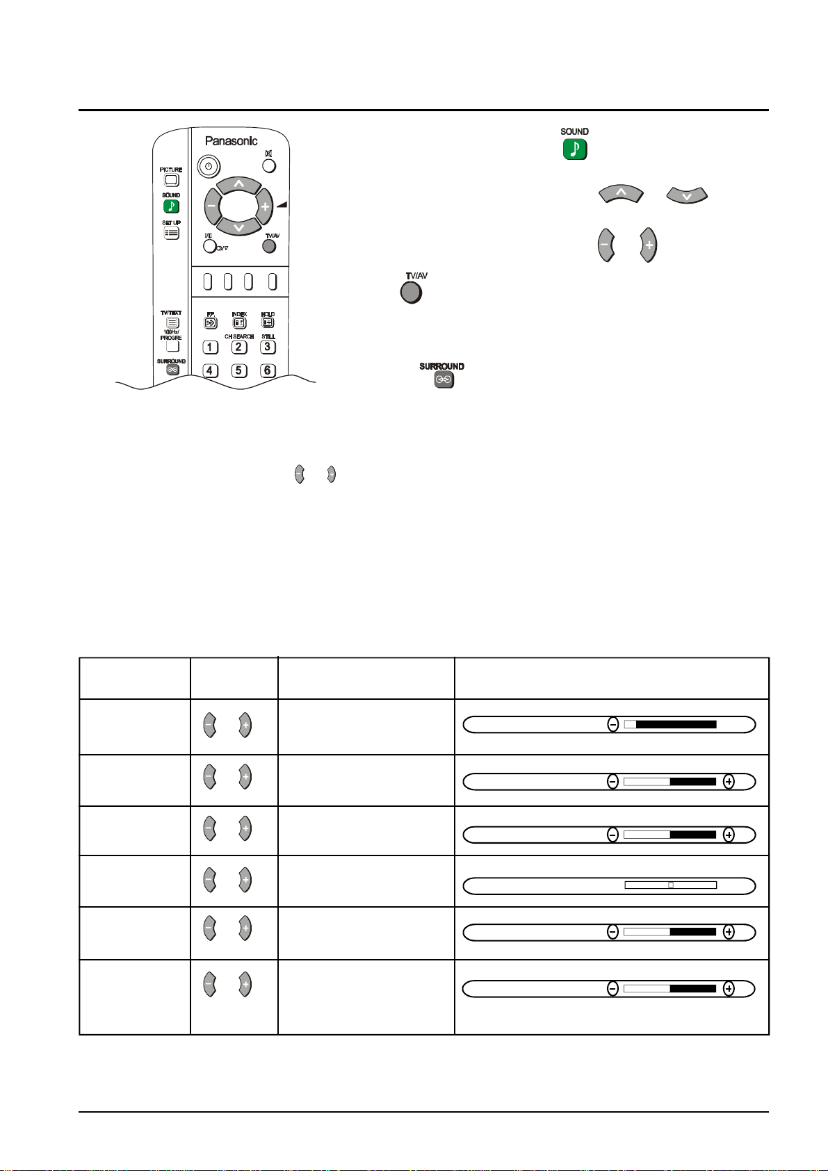
1 Push the SOUND button .
2 Move to the option menu using or .
3 Adjust the chosen option using or .
Push at any time to return to watching TV.
Some features are only available with the SURROUND feature
switched off.
Push the button to switch the SURROUND on or off.
MENU The MENU control allows you to change the Sound
setting between Dynamic, Standard and Soft.
Use the or buttons to switch between settings.
DYNAMIC Amplifies the low frequencies and outputs optimum sound. Used
for music programmes.
STANDARD For normal use.
SOFT Human voices (middle pitch sounds) will be more clear. Used for
News broadcasts etc.
VOLUME, BASS, TREBLE, BALANCE, HEADPHONE VOL.
Item Effect Function On-Screen Indication
Adjusts the output volume.
VOLUME
Quieter Louder
VOLUME
Used to boost or cut low
BASS frequency sounds.
Cut Boost
BASS
Used to boost or cut high
TREBLE frequency sounds.
Cut Boost
TREBLE
Adjusts the sound balance
BALANCE between the left and right
Left SP Right SP speakers.
BALANCE
Adjust for output volume
HEADPHONE VOL for the headphones.
Quieter Louder
HEADPHONE VOL
Adjust for output volume
SUB HEADPHONE for the headphones.
SUB HEADPHONE
(TX-76PW10A Quieter Louder
only)
Notes:
1. You can change the level for each function (Bass and Treble) for each sound menu option.
2. Sound menu levels can be set for TV, AV1, AV2, AV3 and AV4 modes.
3. BALANCE is not displayed when SURROUND is on.
15
Page 16
Sound Menu Operation
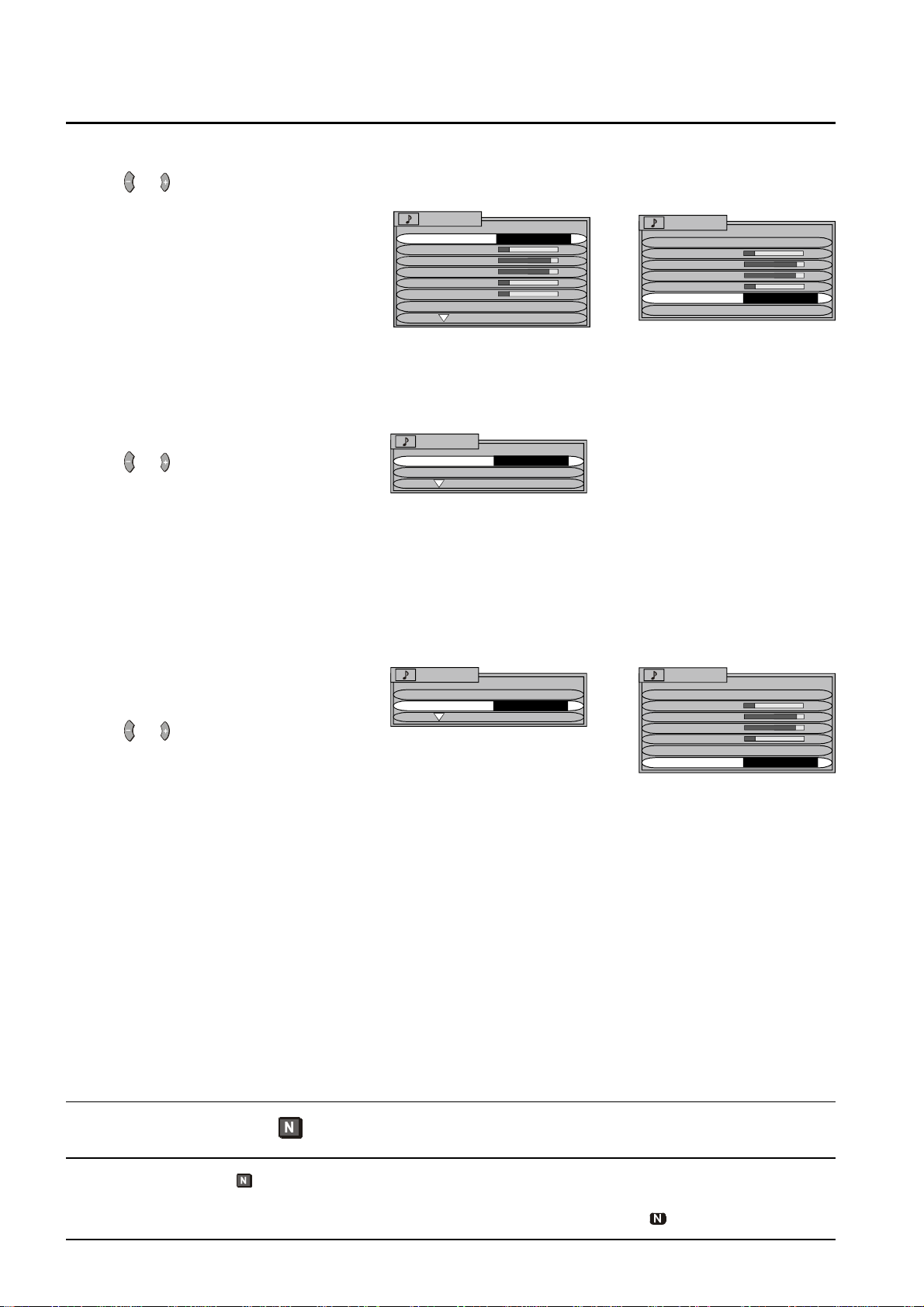
SUBWOOFER
This function allows you to switch the SUBWOOFER between OFF, NORMAL and FULL modes.
Use the or buttons to switch between settings.
OFF
Turns the SUBWOOFER off.
NORMAL
Provides a mid-level bass effect.
FULL
Provides enhanced bass effect.
SOUND
MENU STANDARD
VOLUME
BASS
TREBLE
HEADPHONE VOL
SUB HEADPHONE
SUBWOOFER NORMAL
SOUND
MENU STANDARD
VOLUME
BASS
TREBLE
HEADPHONE VOL
SUBWOOFER NORMAL
SURROUND MENU ON
TX-76PW10A TX-76PW05A
DIGITAL AUDIO (TX76PW10A only)
Use the or buttons to switch between
settings. (OFF, AV1, AV2, AV3 and AV4)
SOUND
DIGITAL AUDIO OFF
SURROUND MENU
If you do not have a digital audio input, set
the option to OFF.
If you have a digital audio input from external equipment such as a DVD player switch the digital audio to the
corresponding AV input. For example if the DVD is connected to AV2, set the digital audio to AV2.
SURROUND MENU
This function allows you to switch the
Surround Sound on or off (TX-76PW05A) or
select the Surround options (TX-76PW10A).
Use the or buttons to switch between
settings.
SOUND
DIGITAL AUDIO OFF
SURROUND MENU ACCESS
SOUND
MENU STANDARD
VOLUME
BASS
TREBLE
HEADPHONE VOL
SUBWOOFER NORMAL
SURROUND MENU ON
TX-76PW10A TX-76PW05A
Normalisation N
Pressing the Normal ( ) Button on the remote control, when the Sound Menu is displayed will return all
sound settings to the factory preset levels. This is called “Normalisation”.
Normalisation will not occur if the Sound Menu is not displayed when the Normal ( ) Button is pressed.
16
Page 17
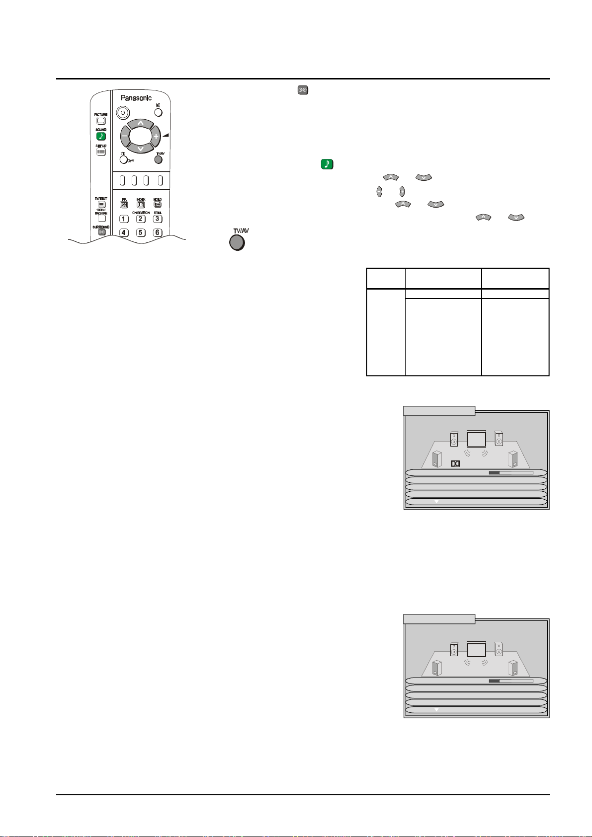
Surround Sound Operation (TX-76PW10A only)
Push the Surround ( ) to confirm that the Surround feature is On. If the on
screen message that appears indicates Surround is Off, Push again to turn the
feature On.
Note: If Surround is Off, the sound output is two channel (ie: left and right)
stereo or mono.
1 Push the SOUND ( ) button.
2 Select to Surround menu by using or .
3 Access Surround menu by using or
4 Move to chose menu option by using or .
5 Adjust chosen option or access chosen menu by using or .
Push to go back to watching TV.
If a DTS / Dolby Digital input is detected the Surround menu
options instantly change - Surround mode is not available. (The
DVD output must be labelled “DTS” or “Dolby Digital”). Ensure that
the Digital Audio option in the SOUND menu is set to the correct
AV input (see page 42). A message displayed in the centre of the
screen shows whether the signal is DTS or Dolby Digital, and
gives a code indicating which channels are detected (see table to
the right). Subwoofer output is not listed; if a subwoofer channels
is detected then its contents are output.
VOLUME
The volume adjustment sets the overall Surround output
volume.
SURROUND
MODE
When a DTS/ Dolby Digital input is not detected this option
is shown. Choose between PRO LOGIC and SIMULATED.
The mode chosen here dictates the next menu option.
SPEAKER
SETTING/
SIMULATED
If a DTS / Dolby Digital input is detected, or if Pro Logic is
selected in Surround mode, this menu option is Speaker
setting, allowing selection of NORMAL, PHANTOM or 3
STEREO modes, as described on page 19.
If Simulated is selected in Surround mode, this menu
option is Simulated setting, allowing selection of DISCO,
MOVIE or STADIUM modes, as described on page 19.
SPEAKER
Allows adjustment of the volume for each speaker, as
LEVEL described on page 19.
Code Front Rear
1+1 Dual mono output
1/0 Mono output
2/0 ü ü
3/0 ü ü ü
2/1 ü ü Mono output
3/1 ü ü ü Mono output
2/2 ü ü ü ü
3/2 ü ü ü ü ü
outputs surround outputs
Left Right Centre Left Right
SURROUND MENU
VOLUME
SPEAKER SET PHANTOM
SPEAKER LEVEL
FRONT DISTANCE 3M
Digital 3/2
If a DTS / Dolby Digital Input is
detected, the Surround menu is
as shown above. This does not
occur if the DVD output is PCM.
FRONT
DISTANCE
REAR
DISTANCE
INTERNAL
SPEAKER
Allows setting of the distance from the listening position to
the front speakers.
Distances or 1, 2, 3, 4, 5, 6, 7 or 8M can be selected.
Allows setting of the distance from the listening position to
the rear speakers. If the rear surround speakers are closer
to you than the centre speaker, you may hear “dialogue
leakage” from the rear surround speakers. It may be
necessary to reduce the volume of the rear speakers.
Distances or 1, 2, 3, 4, 5, 6, 7 or 8M can be selected.
If you do not have an external centre speaker connected,
set to On. If you wish to connect an external centre
speaker then switch Off, see page 43 for connection
details.
SURROUND MENU
VOLUME
SURROUND MODE PRO LOGIC
SIMULATED SET PHANTOM
SPEAKER LEVEL
If no DTS / Dolby Digital input is
detected, Surround mode
appears as a menu option.
17
Page 18
Surround Sound Operation (TX-76PW10A only)
Surround Sound Systems
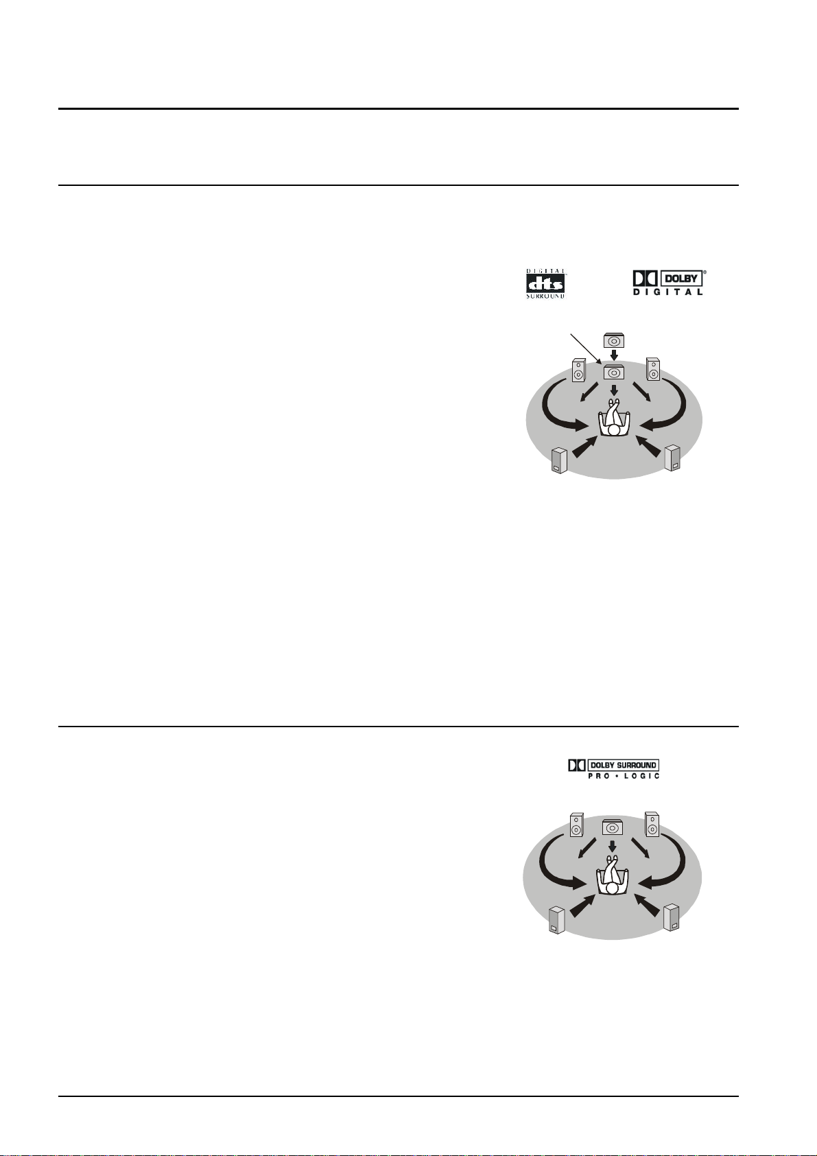
Stereo reproduction normally uses left and right speakers, but Digital Theater System and Pro Logic Surround
go further, adding a centre and other channels so you are immersed in sound and special effects.
Digital Theater Systems (DTS) I Dolby Digital
Both DTS and Dolby Digital split soundtrack information into 6
separate channels of sound which are output through the speaker
setup: five full range channels (left, center, right, left surround,
right surround) and a ‘0.1’ (i.e.: limited range) bass channel. This
gives you superb sound quality from DTS / Dolby Digital encoded
tracks when a compatible speaker system is connected to your
TV. Most dialogue comes from the centre channel, which enhances
dialogue and focuses it so it seems to come from the action on
screen. The separate rear left and right channels give a dramatic
sense of space, with sounds travelling in all directions between
front, centre and rear channel speakers (e.g.: a rocket going
overhead starts behind you to the left and explodes in front of you
to the right). The ‘0.1’ Low Frequency Effects (LFE) channel gives
impact to bass sounds and to special effects more felt than heard
(e.g.: the thud of a dinosaur footfall or the rumble of thunder). While
DTS and Dolby, Digital are both high quality, ‘5.1’ channel surround
systems, the two systems differ in how they break down and store
sound information They also differ in how they work with existing
speaker setups. Dolby Digital has been designed to be backwardly
compatible with Dolby Pro Logic and conventional stereo setups.
DTS on the other hand, focuses on the high quality, 5.1 channel
surround output choosing not to develop backward compatibility
with existing sound systems.
Subwoofer /
LFE Speaker
Left
Front
Speaker
Left
Rear
Surround
Speaker
DTS/Dolby Digital setup
Centre
Speaker
Right
Front
Speaker
Right
Surround
Speaker
Rear
Note:
External equipment is usually connected to the TV via one of the AV terminals to provide pictures and sound
(e.g. a VCR player connected to AV2). To receive a DTS or Dolby Digital encoded soundtrack from compatible
equipment (e.g.: a DVD player, a set top box) you will also need to connect an optical or coaxial cable to one of
the TV’s digital audio sockets. See page 42 for connection details. Also see the Digital Audio option in the
SOUND menu, page 16.
Dolby Pro Logic
Dolby Pro Logic surround uses four channels of sound: left, right,
centre and a rear channel giving excellent reproduction of Pro Logic
encoded tracks when a compatible speaker system is connected
to your TV. Most dialogue comes from the centre channel, which
Left
Front
Speaker
Centre
Speaker
Right
Front
Speaker
enhances dialogue and focuses it so it seems to come from the
action on screen. The rear channel is used to immerse you in
atmosphere and special effects, the same output is sent to both
rear speakers.
As with Dolby Digital, Pro Logic is backwardly compatible with a
conventional stereo speaker setup.
Left
Rear
Surround
Speaker
Right
Rear
Surround
Speaker
Dolby Pro Logic setup
Note:
To get Pro Logic information from Pro Logic encoded TV programmes; you must be able to receive stereo
transmissions. If stereo transmissions are not transmitted in your area then the Pro Logic information will not be
present on TV transmissions and Pro Logic decoding will only produce a centre channel output.
18
Page 19
Surround Sound Operation (TX-76PW10A only)
Left Front
Dolby Digital and Pro Logic modes
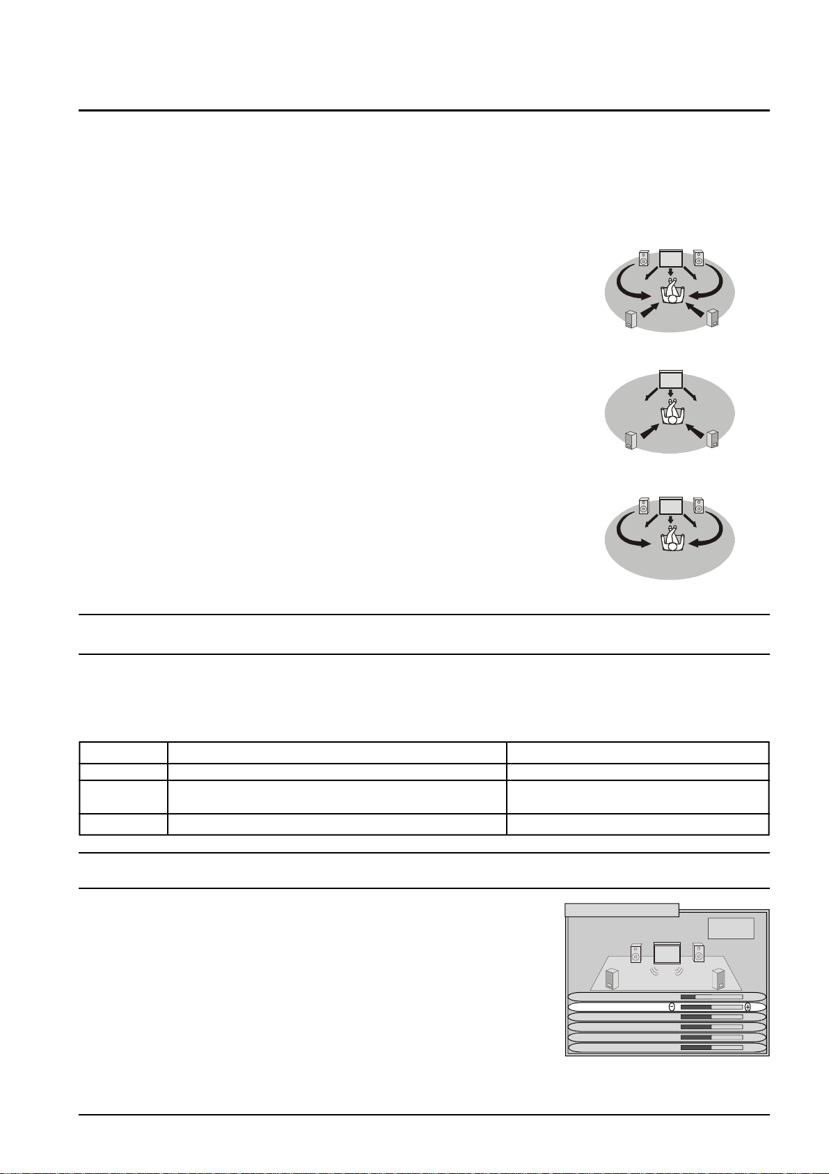
For Dolby Digital input or Pro Logic selected in Surround mode, the following three modes of operation are available
as the speaker setting: Normal, Phantom, 3 Stereo.
Normal If front and rear speakers are connected, use Normal mode. Centre
Right
speaker information will be produced by the TV’s internal left and right
speakers. With a DTS/ Dolby Digital 5.1 input, the LFE speaker
information is produced by the TV’s internal subwoofer. If the internal
speaker is switched off (see page 17) and an external centre speaker
used, the speaker must be connected using RCA cables, via an
external amplifier (otherwise it will not output any sound). See page 42
for connection details.
Phantom If front left and right speakers are not connected, use Phantom mode.
Left, right, and centre information will now be produced by the TV
speakers. If you choose to use this mode with the internal speaker
switched off and front left and right speakers connected, these must be
connected using RCA cables, via an external amplifier (otherwise they
will not output any sound). See page 42 for connection details.
3 Stereo This is the best mode to use if rear speakers are not connected. When
using this mode, the surround information is redirected to the front left
and right speakers. Centre information is output by the TV’s internal
speakers. If the internal speaker is switched off (see page 17) and an
external centre speaker used, it must be connected to the TV using
RCA cables, via an external amplifier (otherwise it will not output any
sound). See page 38 for connection details.
Speaker
Left
Rear
Surround
Speaker
Rear
Surround
Speaker
Left Front
Speaker
Speaker
Right
Surround
Speaker
Right
Surround
Speaker
Right
Speaker
Front
Rear
Rear
Front
Simulated Mode
Simulated modes allow various types of surround effects to be produced by mimicking both the direct sound, as
heard by the audience, and the sound reflected back from the surrounding walls, ceiling and floor in places
such as a discos, stadiums etc. There are three different effects to choose from, each reflecting a different
atmosphere:
Setting Appropriate sources Effect
DISCO Disco, dance or jazz music A crowded nightclub
MOVIE All movies or music software recorded without Dolby Simulates a surround sound recording
Surround
STADIUM Any live sports occasion A packed sports stadium
Speaker Level Setup
The speaker output levels from the different options, e.g.: Left, Centre,
Right, Rear right and Rear left, should be adjusted from your usual listening
position, to obtain the best results. The level can be set using either the TV
sound or the test signal provided. Pushing the SURROUND button switches
between the test signal and TV sound.
Notes:
The adjustment menu available will vary according to the mode chosen.
If you have a DTS / Dolby Digital 5.1 input, and are using the internal
subwoofer to produce the LFE information, you can change the LFE volume
by altering the Subwoofer setting in the SOUND menu. (see page 16).
When using external stereo equipment it is advisable to set the speaker levels to the midpoint position.
SPEAKER LEVEL SETUP
VOLUME
LEFT
CENTRE
RIGHT
REAR RIGHT
REAR LEFT
-SURROUNDTest signal
Off / On
19
Page 20
Set Up Menu Operation
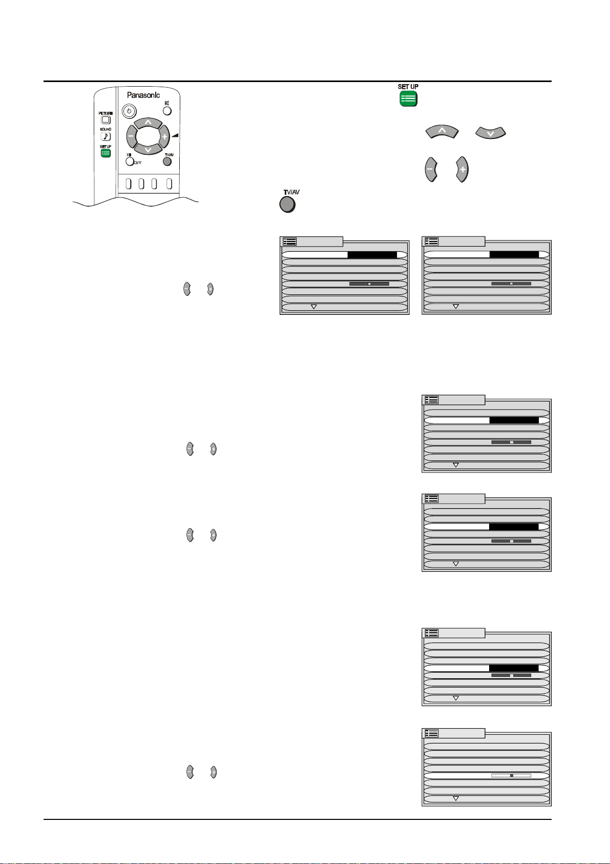
1 Push the SET UP button .
2 Move to the option menu using or .
3 Adjust the chosen option using or .
Push at any time to return to watching TV.
TELETEXT This control allows you to
change between LIST and
TOP or FASTEXT modes.
Use the or buttons to
switch between settings.
SET UP MENU
TELETEXT TOP
OFF TIMER OFF
FLICKER REDUC DYNAMIC
STROBE
CH COLOUR SET
VCR/GAME OFF
TEXT SELECT ENGLISH
AUSTRALIA NEW ZEALAND
TOP mode is the current preferred method in Australia.
FASTEXT mode is the current preferred method in New Zealand.
OFF TIMER The Off-Timer turns the television off after a period of
time chosen by you. The timer settings (in minutes) are
OFF, 15, 30, 45, 60, 75, 90.
Use the or buttons to switch between settings.
FLICKER REDUCTION
This lets you control any unwanted picture movement.
The settings are OFF, NORMAL and DYNAMIC.
Use the or buttons to switch between settings.
OFF No flicker reduction is applied.
NORMAL Used to correct picture movement or if
slight ghosting occurs when using DYNAMIC.
DYNAMIC Activates motion compensation to smooth the image and gets rid of
picture movement.
SET UP MENU
TELETEXT FASTEXT
OFF TIMER OFF
FLICKER REDUC DYNAMIC
STROBE
CH COLOUR SET
VCR/GAME OFF
TEXT SELECT ENGLISH
SET UP MENU
TELETEXT TOP
OFF TIMER OFF
FLICKER REDUC DYNAMIC
STROBE
CH COLOUR SET
VCR/GAME OFF
TEXT SELECT ENGLISH
SET UP MENU
TELETEXT TOP
OFF TIMER OFF
FLICKER REDUC DYNAMIC
STROBE
CH COLOUR SET
VCR/GAME OFF
TEXT SELECT ENGLISH
STROBE Lets you take a series of freeze-frame photos of a piece
of action such as the finish or a race etc.
CH COLOUR SET Colour density varying between broadcast channels can
be adjusted to three levels for each channel received.
Use the or buttons to switch between settings.
20
SET UP MENU
TELETEXT TOP
OFF TIMER OFF
FLICKER REDUC DYNAMIC
STROBE ACCESS
CH COLOUR SET
VCR/GAME OFF
TEXT SELECT ENGLISH
SET UP MENU
TELETEXT TOP
OFF TIMER OFF
FLICKER REDUC DYNAMIC
STROBE
CH COLOUR SET
VCR/GAME OFF
TEXT SELECT ENGLISH
Page 21
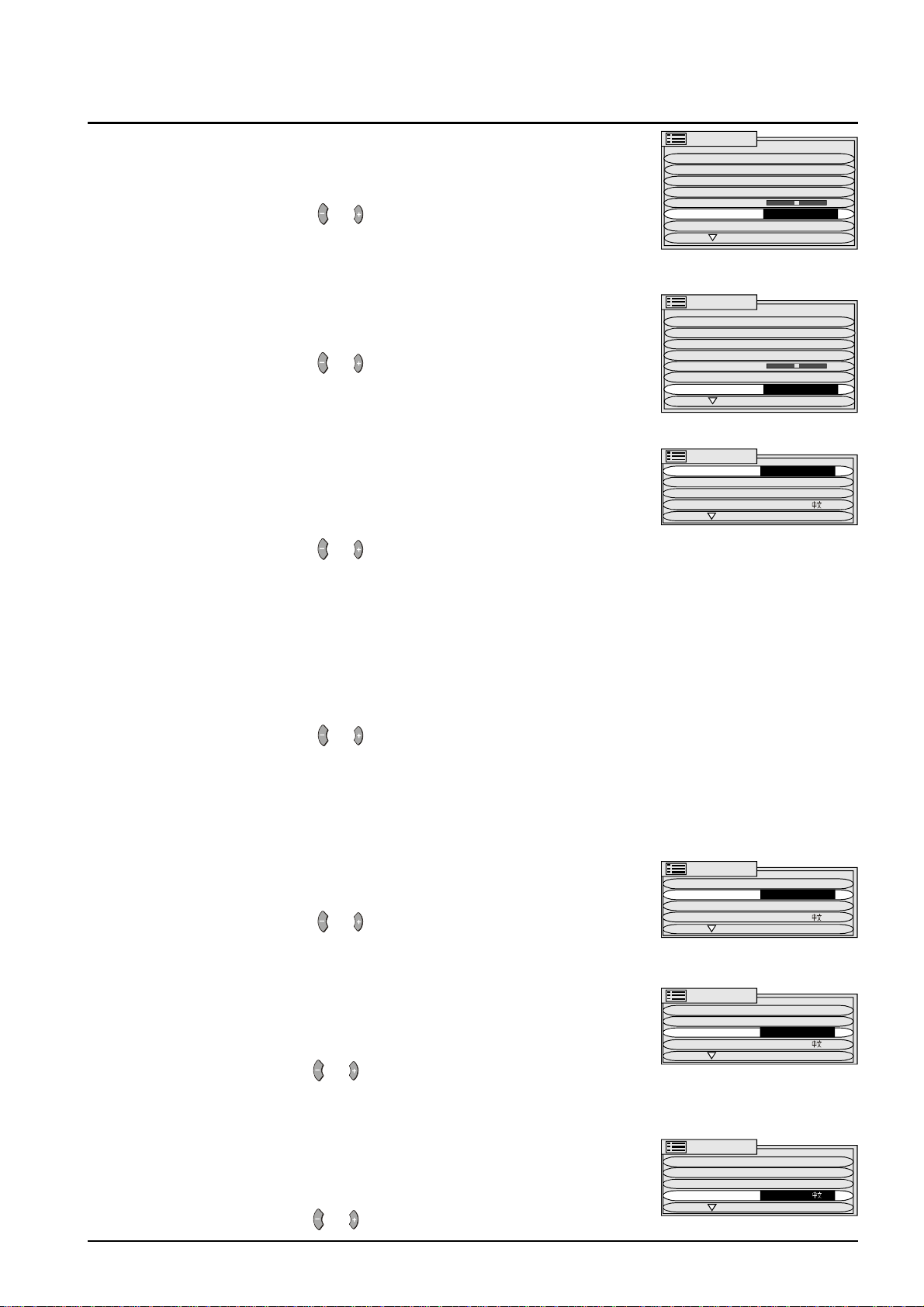
Set Up Menu Operation
VCR/GAME Reproduction of irregular signals such as certain video
games or some rental video tapes may be improved by
turning the VCR/GAME feature On.
Use the or buttons to switch VCR/GAME on or off.
TEXT SELECT Select the character set so that all characters needed
are available for text on teletext pages. The languages
available are ENGLISH, CIS and E.EUROPE.
Use the or buttons to switch between languages.
CHILD LOCK CHILD LOCK allows you to “lock out” a channel to
prevent a child from watching or hearing a particular
programme. Select the channel or AV to be locked
before pressing the SET UP button.
Use the or buttons to switch the CHILD LOCK on or
off.
SET UP MENU
TELETEXT TOP
OFF TIMER OFF
FLICKER REDUC OFF
STROBE
CH COLOUR SET
VCR/GAME OFF
TEXT SELECT ENGLISH
SET UP MENU
TELETEXT TOP
OFF TIMER OFF
FLICKER REDUC OFF
STROBE
CH COLOUR SET
VCR/GAME OFF
TEXT SELECT ENGLISH
SET UP MENU
CHILD LOCK OFF
TUNING MENU
GEOMAGNETIC
LANGUAGE ENGLISH
COLOUR SYSTEM
COLOUR SYSTEM is only available in AV mode. This option allows you to select the
correct colour system for the signal being received. If a clear picture with correct
colours cannot be obtained, a change to the Colour System may improve the picture.
The settings are AUTO, PAL, NTSC4.43 and NTSC3.58. The Australian and New
Zealand colour system is PAL.
Use the or buttons to switch between settings.
Note: PAL and NTSC3.58 are different colour signal broadcast transmission
systems applicable to differing countries. NTSC4.43 is a system used in
special VCRs to playback NTSC recorded tapes on a PAL television.
TUNING MENU This provides access to many other features including
system select and tuning options.
Use the or buttons to access the TUNING MENU.
GEOMAGNETIC If you notice a slight tilt in the picture or if there are
coloured patches at the corners of the screen, use this
feature to eliminate them. Refer to page 31.
Use the or buttons to access the
GEOMAGNETIC Adjustment Menu.
SET UP MENU
CHILD LOCK OFF
TUNING MENU ACCESS
GEOMAGNETIC
LANGUAGE ENGLISH
SET UP MENU
CHILD LOCK OFF
TUNING MENU
GEOMAGNETIC ACCESS
LANGUAGE ENGLISH
LANGUAGE When you first install the TV the On Screen Display
language is set to English. The language can also be
set to Chinese,.
Use the or buttons to switch between languages.
SET UP MENU
CHILD LOCK OFF
TUNING MENU
GEOMAGNETIC
LANGUAGE ENGLISH
21
Page 22
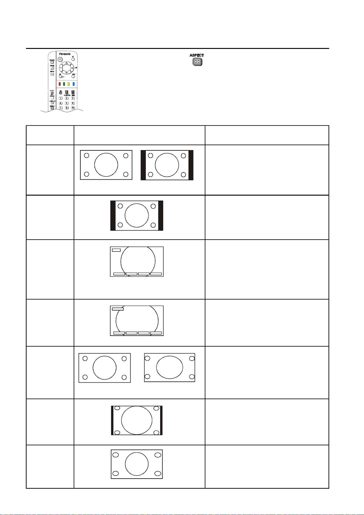
Aspect Controls
Press the ASPECT button to select the different Aspect options. The
options available are AUTO, 4:3, ZOOM, S-ZOOM, 16:9, 14:9 and JUST.
Mode Picture Description
AUTO The AUTO position can be set to 4:3 or to
JUST. When a wide screen signal is
detected at the Video terminal the TV will
select the16:9 aspect ratio.
16:9 Signal 4:3 Signal
4 : 3 This option will display a standard 4:3
picture without any stretching or
compression. There will be vertical black
lines down either side of the picture
ZOOM This option allows you to magnify part of
ZOOM
the picture. The coloured buttons let you
change the position of the magnified area.
H - POS - H - POS + V - POS - V - POS +
Red H POS - Move picture Left
Green H POS + Move picture Right
Yellow V POS - Move picture Down
Blue V POS + Move picture Up
S - ZOOM S-ZOOM displays part of the picture at
S - ZOOM
greater magnification that the ZOOM
mode does. The coloured buttons let you
H - POS - H - POS + V - POS - V - POS +
change the position of the magnified area
as shown for ZOOM..
16 : 9 The 16:9 option will display the picture at
its maximum size. Signals in the 4:3
format will be stretched to fit the picture.
16:9 Signal 4:3 Signal
14 : 9 The 14:9 option will display a 4:3 signal in
simulated wide screen. The picture is
slightly stretched. It is also slightly
cropped top and bottom.
JUST JUST gives you a “best fit” option when
showing 4:3 on wide screen. The centre
of the picture is not affected but there is
some stretching at the edges.
22
Page 23
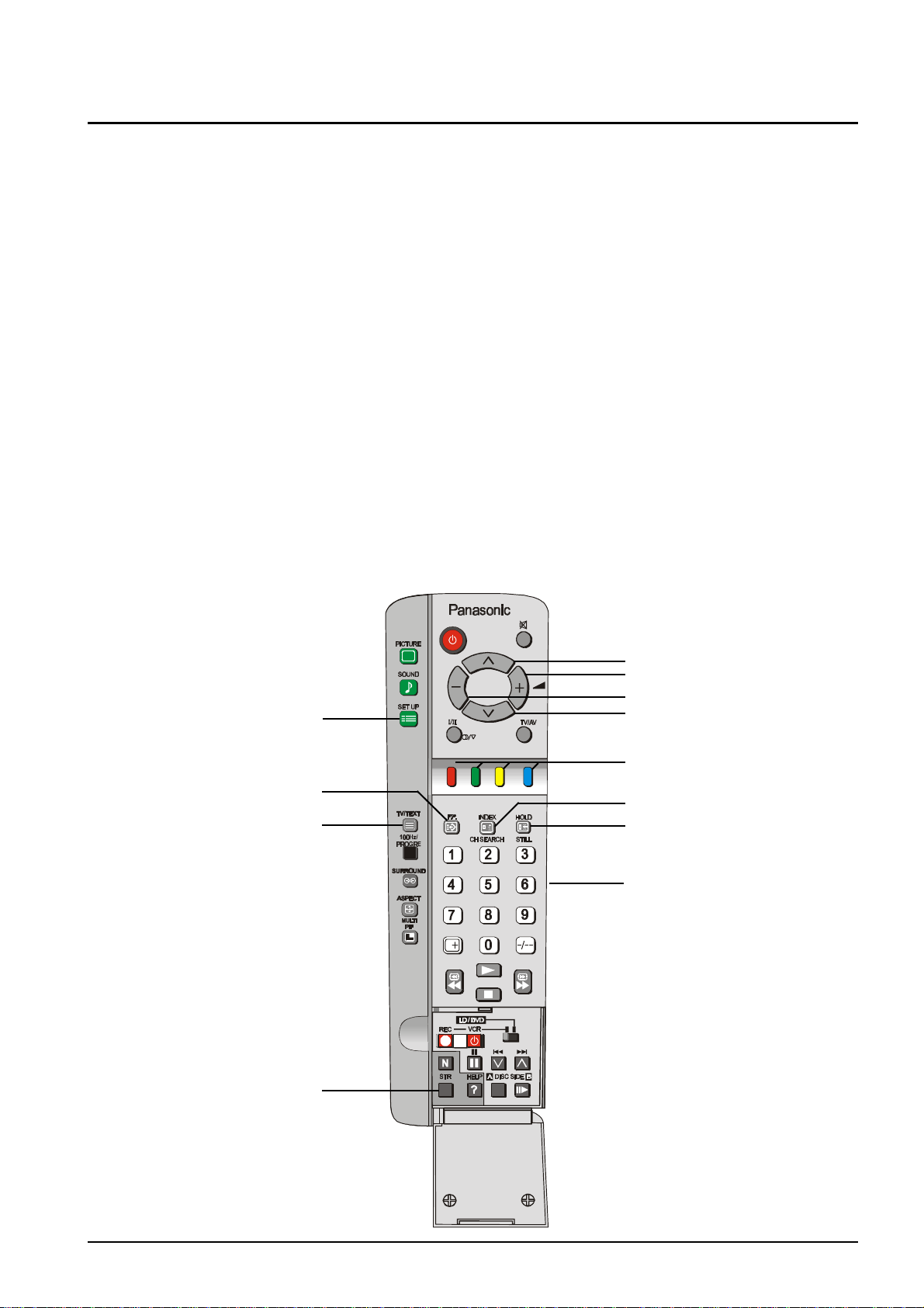
TELETEXT Operation
Teletext is only available on certain broadcast channels. The time taken to display the pages and sub-pages is
set by the teletext transmitter and not by the television.
Teletext is also used for Closed Captioning of television programmes for the hearing impaired. Closed captions
can be found on Teletext Page 801.
TOP (Table Of Pages) MODE
In TOPTEXT mode, the red button moves to the previous page number and the green button moves to the
next page number. The yellow and blue buttons correspond to different subjects. These subjects can be
accessed by Pushing the coloured button. This is the current preferred method of operation in Australia.
FASTEXT MODE
In FASTEXT mode, four differently coloured subjects are displayed at the bottom of the screen. To access
more information about one of these subjects, push the corresponding colour coded button on the remote
control. This is the current preferred method of operation in New Zealand.
LIST MODE
In LIST mode, four different coloured page numbers are shown at the bottom of the screen. Each of these
numbers can be altered and stored in the TV’s memory. These coloured page numbers correspond to the
colour coded buttons on the remote control.
Please refer to page 20 for instructions on how to change modes between TOP/FASTEXT and LIST.
SET UP
Favourite Page
TV / TEXT
Store
Page Number Up
Sub Page Number Up
Sub Page Number Down
Page Number Down
Coloured Buttons.
Index
Hold
Page Numbers
23
Page 24
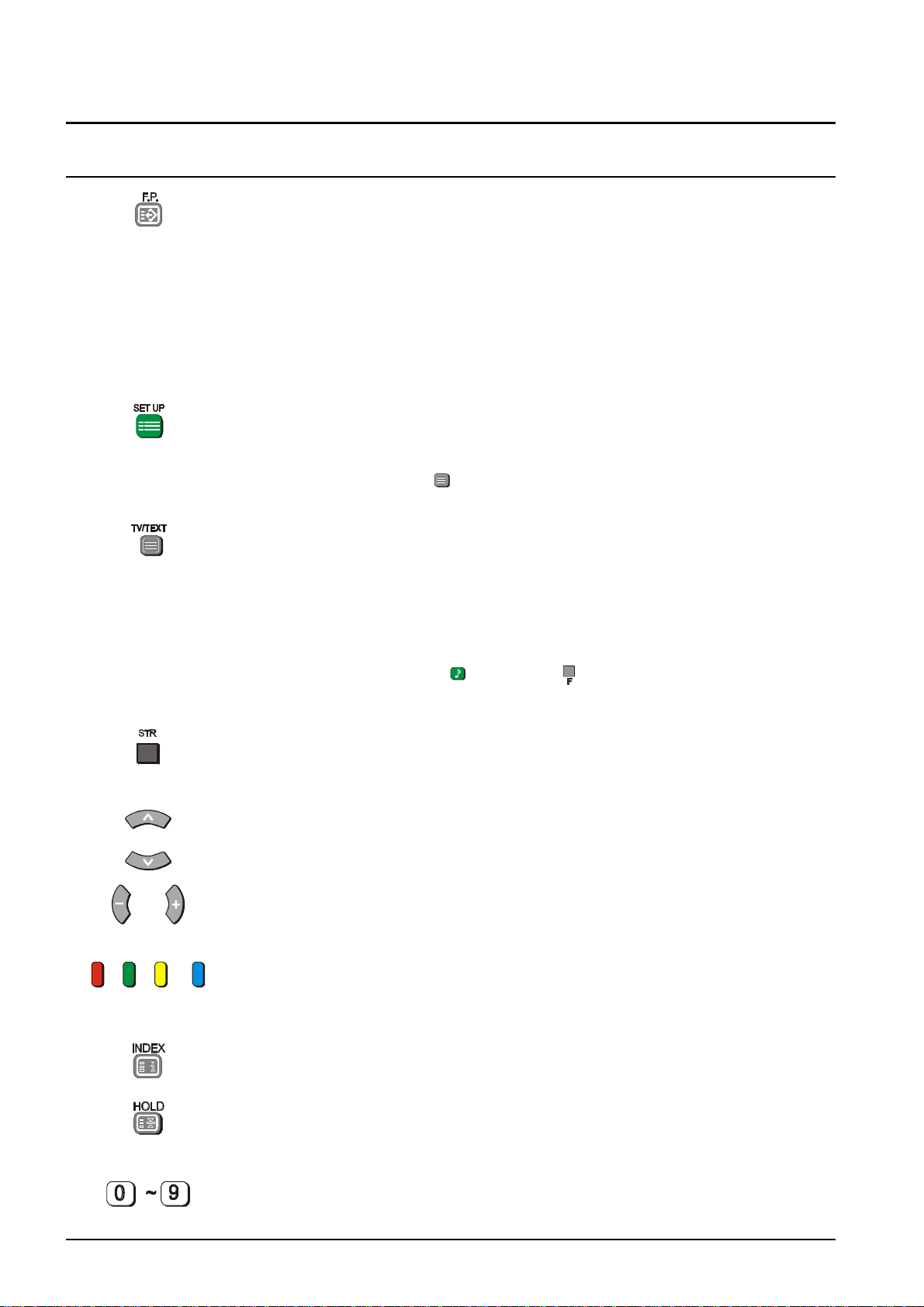
TELETEXT Operation
BUTTON WHAT IT DOES
F.P. (FAVOURITE PAGE)
This feature will store a favourite page in the TV memory.
1. The TV must be in the LIST mode, receiving a teletext broadcast and the
programme number must be between 1 and 25.
2. Push the Blue button.
3. Select the page number.
4. Push and hold the STR button.
5. The page number is now stored.
Push F.P. to recall this page.
SET UP
Used with the Coloured buttons to access the Reveal, Full / Top / Bottom, Display
Cancel and Time Text functions.
Push the TV/TEXT Button to return to normal television viewing.
TV / TEXT
Pressing this button switches the screen between:
- TELETEXT
- Television picture on the left of the screen and the TELETEXT on the right of
the screen.
- Normal television viewing.
When TEXT is on, the sound from the broadcast channel is still audible. To adjust
the volume press the Sound button or the button to display the volume
indicator. The volume can then be adjusted normally.
STR
This button is used to store page numbers into the coloured buttons or the Favourite
Page button. The STR button is located behind the remote control door.
PAGE NUMBERS UP AND DOWN
These buttons are used to move to higher or lower page numbers.
SUB PAGE NUMBERS UP AND DOWN
These buttons are used to move to higher or lower sub page numbers.
COLOURED BUTTONS
These buttons refer to different page numbers in LIST mode and different subjects
in TOP mode.
INDEX
Pressing this button returns you to the main index page.
HOLD
Some TELETEXT pages contain multi-page information. Use this button to stop
the page changing. Push it again to release the hold.
24
PAGE NUMBER BUTTONS
These buttons allow you to directly enter the page number that you want to view.
Please refer to drawing on Page 23 for location of Teletext Control Buttons.
Page 25
TELETEXT Operation
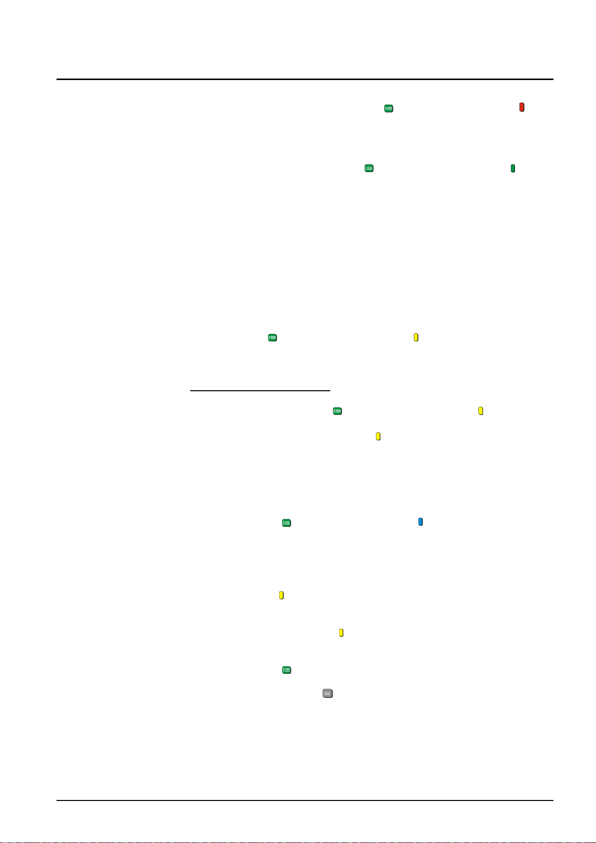
REVEAL Some Text pages contain concealed information, e.g. the solution to a puzzle.
To reveal this information Push the Set Up button followed by the Red
button. To hide the information, Push the Red button again.
F/T/B This button is used when difficulty is experienced in reading text on the screen.
(FULL / TOP / BOTTOM)
DISPLAY CANCEL If you wish to watch the television while you are waiting for a page to be
To operate the F/T/B Push the Set Up button followed by the Green
button.
Operating the F/T/B expands and displays the upper half of the screen.
Operating the F/T/B Button again expands and displays the lower half of the
screen. Operating the F/T/B Button a third time returns the display to normal
condition.
transmitted you can use the DISPLAY CANCEL function.
This function is not available (or necessary) when the picture and the
TELETEXT are both being displayed side by side.
Push the Set Up button followed by the Yellow button to view the TV
picture while waiting for a teletext page to be transmitted. When found, the page
number will be displayed the at the top left of the screen.
News Flash or Other Updates
When a news flash page (or another page which provides regular updates) has
been selected Push the Set Up button followed by the Yellow button to
view the TV picture. When a news flash is received the page number will be
displayed on the screen. Push the Yellow button to display the news flash.
TIME TEXT * When a Page has more than one screen (sub-page) of information, you may
have to wait for some time before the sub-page you require becomes available.
With this function it is possible to enter the number of the desired sub-page.
1. Select Text Mode and choose a page.
2. Push the Set Up button followed by the Blue button. T**** will be
displayed at the top left of the screen.
3. Enter the sub page number before the T**** disappears. The sub-page
number must be entered as a four digit number e.g. sub-page 3 would be
entered as 0003. (If in LIST mode, a “T” will appear in the current box at the
bottom).
4. Push the Yellow button to view the TV picture while waiting for the subpage
to be found. (This function is not necessary when the picture and the
TELETEXT are both being displayed side by side).
5. When found, Push the Yellow button
To clear the page perform one of the following:
- Push the Set Up button.
- Select a new page number.
- Push the TV/TEXT Button to return to normal television viewing.
* Note: TIME TEXT is not currently available in Australia.
25
Page 26
Tuning Menu
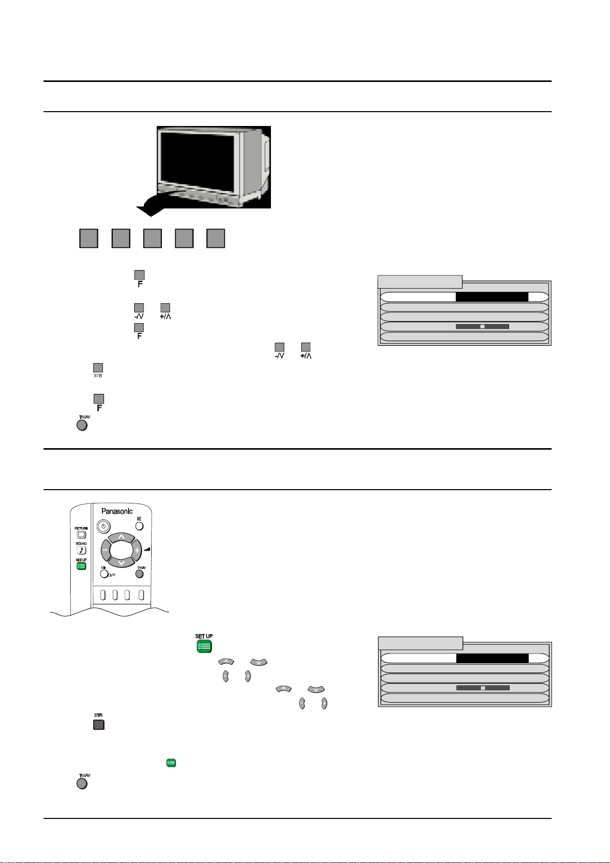
FRONT PANEL CONTROLS
STR F -/\/ +//\ TV/AV
1. Push the
is reached.
2. Push the
3. Push the
4. Adjust the chosen option or menu using
Pressing
setting).
Push the
Push
after making an adjustment will store the setting as the default (and will replace the factory
button to return to the Tuning Menu.
at any time to return to watching TV.
button repeatedly until the Tuning Menu
or Button to select the Tuning Menu.
button to access the Tuning Menu.
REMOTE CONTROL
TUNING MENU
SYS SELECT AUSTRALIA
AUTO TUNE
MANUAL TUNE
FINE TUNE
SKIP OFF
or .
1. Push the SET UP button .
2. Select the Tuning Menu using
3. Access the Tuning Menu using
4. Move to the required option or menu using
5. Select, adjust or switch the chosen option using
Pressing
setting).
Push the SET UP button
Push
after making an adjustment will store the setting as the default (and will replace the factory
to return to the Tuning Menu.
at any time to return to watching TV.
or .
or .
26
or .
or .
TUNING MENU
SYS SELECT AUSTRALIA
AUTO TUNE
MANUAL TUNE
FINE TUNE
SKIP OFF
Page 27
Tuning Menu
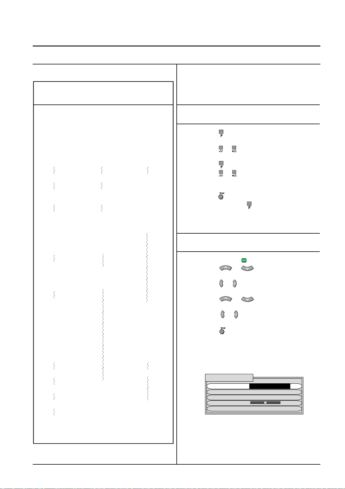
Channel Allocation SYS Select
The channel allocation is as follows:
SYS SELECT AUSTRALIA NZ/INDONESIA
CH DISP RECEIVED CHANNEL
0 - 1 0 1
2 1 2
3 2 3
4 3 4
5 4 5
6 5 6
7 S2 7
11 S6 11
-
15 S10 16 6 -
-
19 9 20 9A 21 10 21
22 11
23 12
24 S11
This option allows you to switch the television system
between the Australian and the New Zealand / Indonesian
system.
Using the Front Panel
1. Push the button repeatedly until the Tuning
Mode is reached. (See page 26).
2. Push the or Button to access the Tuning
Menu.
3. Push the button to select SYS SELECT.
4. Push the or Button to switch between
AUSTRALIA and NZ/INDONES.
5. To return the television to normal operation
push the button on the remote control or
repeatedly push the button until the volume
display appears.
Using the Remote Control
28
57 S44
58 20
59 21
73
74 S’1
75 S’2
76 S’3
77 78 79 80 S1
81 S2
89 S10
118 80
-
120 - S41
- -
125 - -
1. Push the Set Up ( ) button.
2. Push the or button to access the
Tuning Menu. (See page 26.
3. Push the or button to select the Tuning
Menu.
4. Push the or button to select the SYS
SELECT.
5. Push the or Button to switch between
AUSTRALIA and NZ/INDONES.
6. Push the button to return the television to
normal operation.
TUNING MENU
SYS SELECT AUSTRALIA
AUTO TUNE
MANUAL TUNE
FINE TUNE
SKIP OFF
27
Page 28
Tuning Menu
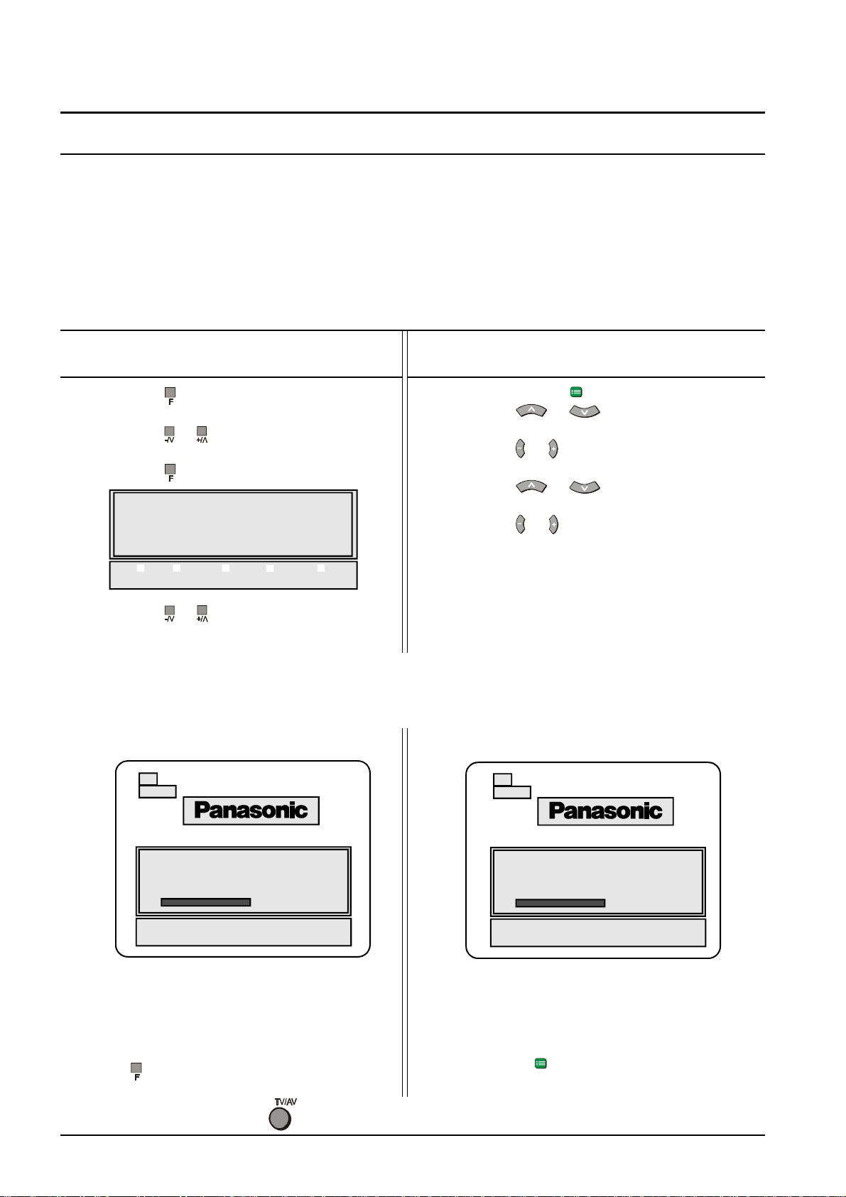
Auto Tune
This television has been factory tuned to all major city channels. Use the automatic tuning procedure only if you wish
to reset ALL Programme Location Numbers. Refer to “Manual Tune” on page 30 if you only want to retune one or
two Programme Location Numbers.
The television should be switched ON and the TV/AV Switch set to TV.
When you start the automatic search, the television will automatically search for television broadcasts through both
VHF bands and the UHF band. During this process all of the available television broadcast channels will be automatically allocated to sequential Programme Number locations depending on the mode selected (See page 28).
Using the Front Panel Using the Remote Control
1. Push the button repeatedly until the Tuning
Menu is reached. (See page 26).
2. Push the or Button to access the Tuning
Menu.
3. Push the button to access Auto Tune.
1. Push the Set Up ( ) button.
2. Push the or button to select the
Tuning Menu. (See page 26).
3. Push the or button to access the Tuning
Menu.
4. Push the or button to select the Auto
TUNING MODE
Tune.
5. Push the or button to start the Auto Tune.
F : NO - , + : YES
STR F -/\/ +//\ TV/AV
4. Push the or Button to start the search.
The television will automatically allocate each received broadcast signal to a Programme Number
depending on the mode selected (See page 28). As each station is stored the Panasonic logo will
appear momentarily. The operation will cease when all available channels have been tuned.
29
CH 29
29
CH 29
AUTO SETUP IN PROGRESS
SEARCHING :
STORED CH29
F : RETURN TO TUNING MENU
TV/AV : TO EXIT
Push the button to return the television to the
Tuning Menu.
Push the button to return the television to normal operation.
28
AUTO SETUP IN PROGRESS
SEARCHING :
STORED CH29
SETUP : RETURN TO TUNING MENU
TV/AV : TO EXIT
Push the Set Up ( ) button to return the television to
the Tuning menu.
Page 29
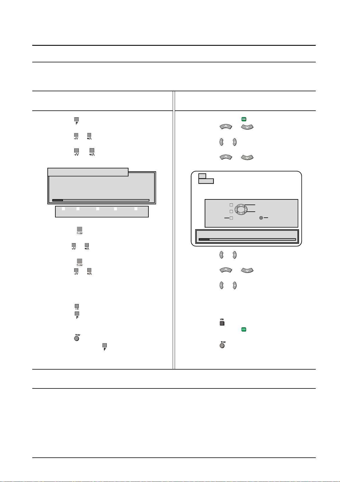
Tuning Menu
Manual Tune
This Television has been factory tuned to all the major city channels. Use this tuning procedure only if you wish to
reset individual Programme Numbers.
The television should be switched ON and the TV/AV Switch set to TV.
Using the Front Panel
1. Push the button repeatedly until the Tuning
Menu is reached.
2. Push the or Button to access the Tuning
Menu. (See page 26).
4. Push the or button to access Manual
Tune.
MANUAL TUNE (FRONT PANEL)
- , + : SEARCH
TV/AV : MOVE CURSOR
STR : TO STORE
F : TO EXIT
STR F -/\/ +//\ TV/AV
5. Push the button to switch to “Change
Programme”.
6. Use the or buttons to select the
programme location number to tune.
7. Push the button to switch to “Search”.
8. Push the or Button to start the search.
9. The television will automatically search for the
next broadcast signal. As each station is
found the search will stop. If you do not want
this station restart the search.
10. Push the to store the selected station.
11. Push the button to return the television to
the Tuning Menu.
12. To return the television to normal operation
push the button on the remote control or
repeatedly push the button until the volume
display appears.
Using the Remote Control
1. Push the Set Up ( ) button.
2. Push the or button to select the
Tuning Menu. (See page 26).
3. Push the or button to access the Tuning
Menu.
4. Push the or button to select the
Manual Tune.
29
CH 29
PROGRAMME -/+
SEARCH -/+
RETURN TV/AV EXIT
“STR” BUTTON - STORE
MANUAL TUNE
5. Push the or button to access the Manual
Tune.
6. Push the or button to select the
programme location number to tune.
7. Push the or button to start the search.
8. The television will automatically search for the
next broadcast signal. As each station is found
the search will stop. If you do not want this
station restart the search.
9. Push the to store the selected station.
10. Push the Set Up ( ) button to return the
television to the Tuning menu.
11. Push the button to return the television to
normal operation.
Tuning the Television to a VCR
1. Turn the VCR On and either start a known tape playing or set the VCR Test Signal, if fitted, to On
(refer to the VCR operating instructions).
2. Repeat steps 2, 3 and 4 of the Manual Tuning procedure above. The television will treat the VCR as if
it was a normal television broadcast station.
NOTES:
1. The antenna lead must be connected to the VCR and the VCR RF-Out must be connected to the TV
RF-In. Please refer to page 36.
2. The picture and sound quality are usually much better if the VCR is connected using the AV
Terminals. Please refer to page 37.
29
Page 30
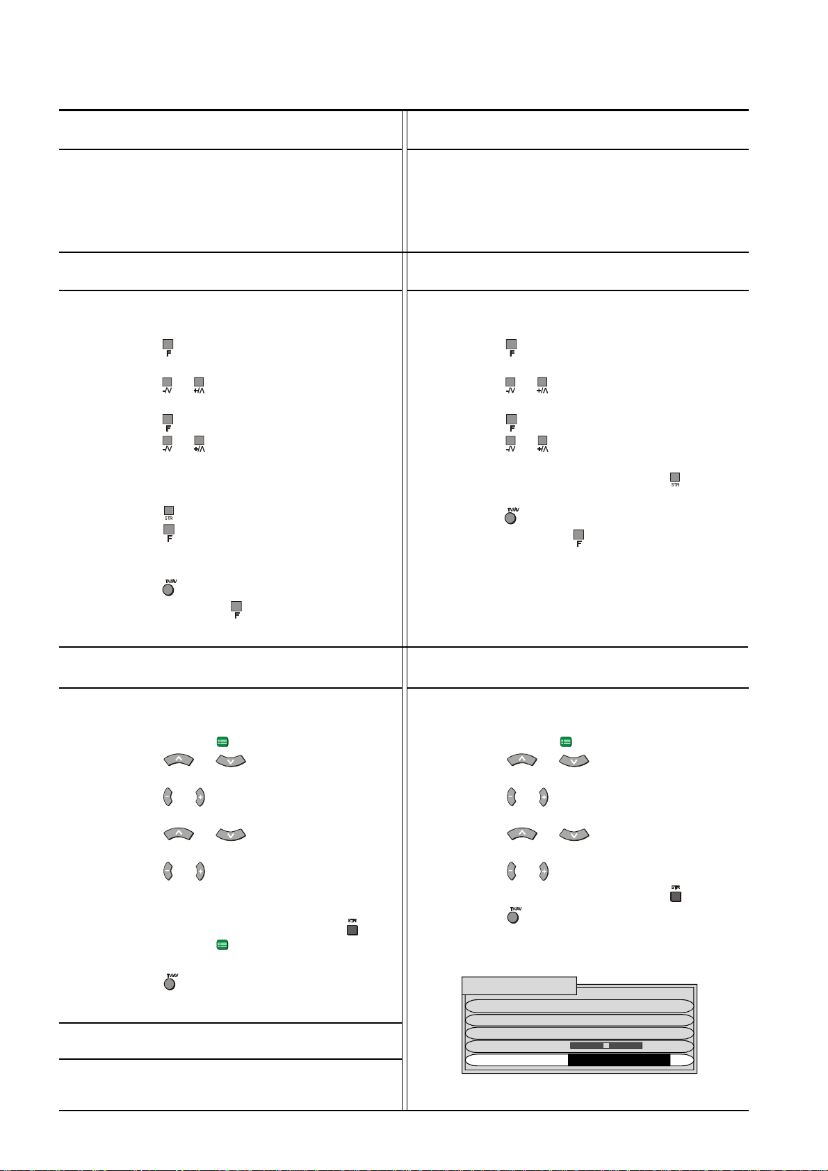
Tuning Menu Fine Tune Skip
In areas of poor reception or constant interference a
slight adjustment to the tuning may improve the
picture quality.
Using the Front Panel
1. Select the Programme location number you
want to fine tune.
2. Push the button repeatedly until the Tuning
Mode is reached. (See page 26).
3. Push the or Button to access the Tuning
Menu.
4. Push the button to access Fine Tune.
5. Push the or Button to fine tune the
station.
6. The television will fine tune in the direction
chosen by you.
7. Push the to store the selected station.
8. Push the button to return the television to
the Tuning Menu.
9. To return the television to normal operation
push the button on the remote control or
repeatedly push the button until the volume
display appears.
This option allows you to “Skip” (bypass) the unused or
undesired Programme Numbers. The Function is only
applicable when the Programme Number Up or down
buttons are Pushed. The use of the remote control Direct
Programme Number Buttons overrides the Skip function.
Using the Front Panel
1. Select the Programme location number you
want to “Skip”
2. Push the button repeatedly until the Tuning
Mode is reached. (See page 26).
3. Push the or Button to access the Tuning
Menu.
4. Push the button to select SKIP.
5. Push the or Button to turn the SKIP on or
off.
6. To store the SKIP setting, push the button.
7. To return the television to normal operation
push the button on the remote control or
repeatedly push the button until the volume
display appears.
Using the Remote Control
1. Select the Programme location number you
want to fine tune.
2. Push the Set Up ( ) button.
3. Push the or button to select the
Tuning Menu. (See page 26).
4. Push the or button to access the Tuning
Menu.
5. Push the or button to select the
Fine Tune.
6. Push the or button to start the fine tune.
7. The television will fine tune in the direction
chosen by you.
8. To store the selected station, push the .
9. Push the Set Up ( ) button twice to return the
television to the Set Up menu.
10. Push the button to return the television to
normal operation.
Canceling the Fine Tuning
To cancel the Fine Tuning follow the Manual Tune
procedure on page 29.
Using the Remote Control
1. Select the Programme location number you
want to “Skip”.
2. Push the Set Up ( ) button.
3. Push the or button to access the
Tuning Menu. (See page 26).
4. Push the or button to select the Tuning
Menu.
5. Push the or button to select the
SKIP.
6. Push the or button to turn SKIP on or off.
7. To store the SKIP setting, push the button.
8. Push the button to return the television to
normal operation.
TUNING MENU
SYS SELECT AUSTRALIA
AUTO TUNE
MANUAL TUNE
FINE TUNE
SKIP OFF
30
Page 31
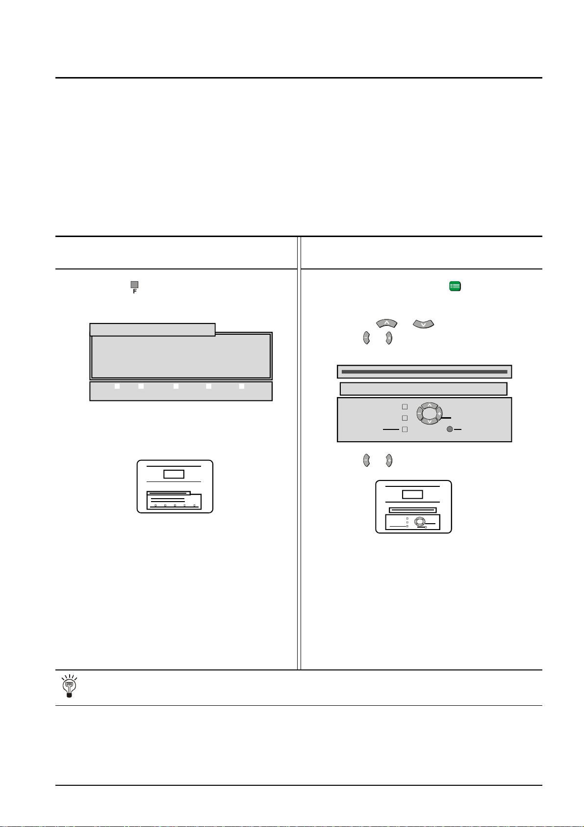
Geomagnetic Correction
Magnetic interference may come from such things as unshielded motors, moving the TV while it is switched
ON, turning off a vacuum cleaner too close to the TV, lightning strikes nearby or many other things.
Slight tilting of the picture may be noticeable or coloured patches may sometimes appear at the corners of
the screen (colour purity).
The Geomagnetic Correction feature can be used to eliminate some interference problems.
Quite often simply switching your Television OFF with the Power On/Off Switch (not with the remote control)
for 30 minutes and then switching it back ON will cure the problem.
Geomagnetic corrections can be made from the remote control or from the TV set.
Using the Front Panel
1. Push the button repeatedly to access the
Geomagnetic Correction Menu.
GEOMAGNETIC CORRECTION
- + : ADJUST TILT
F : TO EXIT
STR F -/\/ +//\ TV/AV
2. Push - / \/ or + / /\ to adjust the picture tilt or
coloured patches as necessary.
000
The adjustment range is from -8 to +8.
Using the Remote Control
1. Push the SET UP button .
2. Select the Geomagnetic Correction Menu by
Pushing or .
3. Push or to access the Geomagnetic
Correction.
GEOMAGNETIC CORRECTION
ADJUST TILT
RETURN TV/AV EXIT
4. Push or to adjust the picture tilt or
coloured patches as necessary.
000
3. Push the F button to return to normal viewing.
The adjustment range is from -8 to +8.
5. Push the SET UP button to return the TV to
the Set Up Menu.
OR
6. Push the TV/AV button to return to normal
viewing.
Helpful HintN
1. If geomagnetic changes cause colour patches on the screen switch your Television OFF with the
Power On/Off Switch (not with the remote control) for 30 minutes and then switch it back ON.
2. Adjustment for geomagnetic should be performed every time the location of the TV is changed.
3. In some cases colour patches will not be completely eliminated even after adjustment, particularly in
ferroconcrete buildings and other structures susceptible to geomagnetic effects. In these cases the TV
location will have to be changed.
31
Page 32
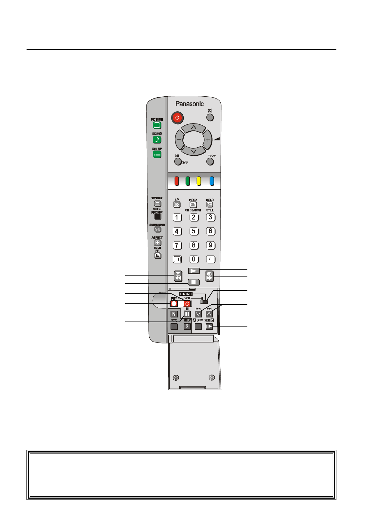
Remote Control VCR/LD/DVD Operation
This remote control has been designed to work with a variety of VCRs, Laser Disc players and DVD players.
Please refer to page 36 for details of manufacturers’ codes.
REWIND / REVIEW
STOP
POWER
RECORD
PAUSE
PLAY
FAST FORWARD / CUE
VCR - LD/DVD SWITCH
PROGRAMME NUMBER
DOWN & UP
STILL ADVANCE / SIDE B
32
* WARNING:
Unauthorised recording of material from Television Broadcasts or from other video
and/or audio sources may contravene copyright laws.
Page 33
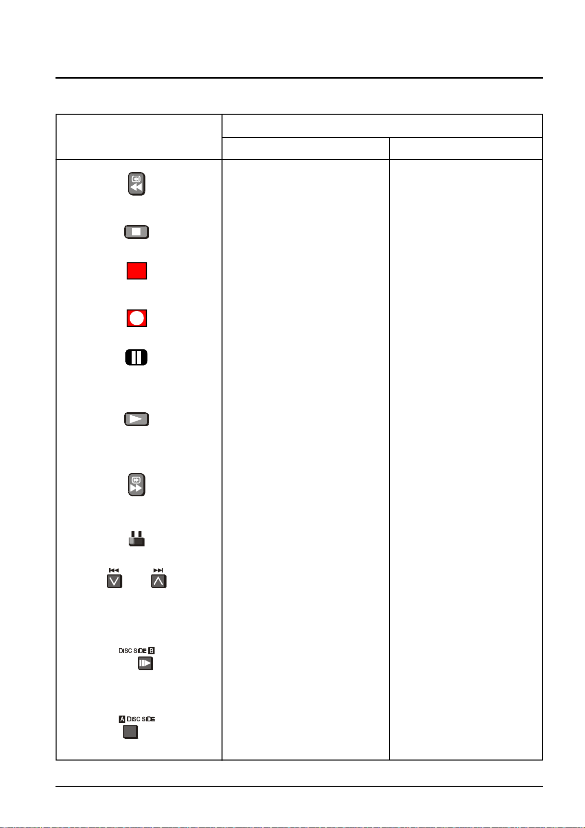
Remote Control VCR/LD/DVD Operation
Remote Control VCR/LD/DVD Buttons
Function
Button / Switch
VCR LD/DVD
REWIND / REVIEW REWIND / REVIEW
Used to rewind the tape Used to play the disc in
quickly or watch the tape reverse while watching the
in reverse. picture.
STOP STOP
Used to stop the VCR. Used to stop the LD/DVD.
POWER BUTTON POWER BUTTON
Used to switch the VCR Used to switch the LD/DVD
ON or OFF (Standby). ON or OFF (Standby).
RECORD
Push both buttons to
Start recording.
PAUSE PAUSE
Pauses the tape during play. Pauses the disc during play.
PLAY PLAY
Used to start the VCR Used to start the LD/DVD
playing. playing.
FAST FORWARD / CUE FAST FORWARD / CUE
Used to wind the tape Used to watch the disc at
forward quickly or to watch fast speed.
the tape at fast speed
VCR Switch Setting LD/DVD Switch Setting
Selects VCR Selects LD/DVD.
PROGRAMME NUMBER PROGRAMME SKIP
DOWN AND UP
Used to select the next Used to skip tracks on the
Higher or lower programme. disc.
Number.
STILL ADVANCE DISC SIDE B SELECTION
Used to advance the tape Used to select the B side
One frame at a time. Used of the disc.
With the Pause button.
DISC SIDE A SELECTION
Used to select the A side
of the disc.
Please refer to drawing on Page 32 for location of VCR/LD/DVD Control Buttons.
33
Page 34
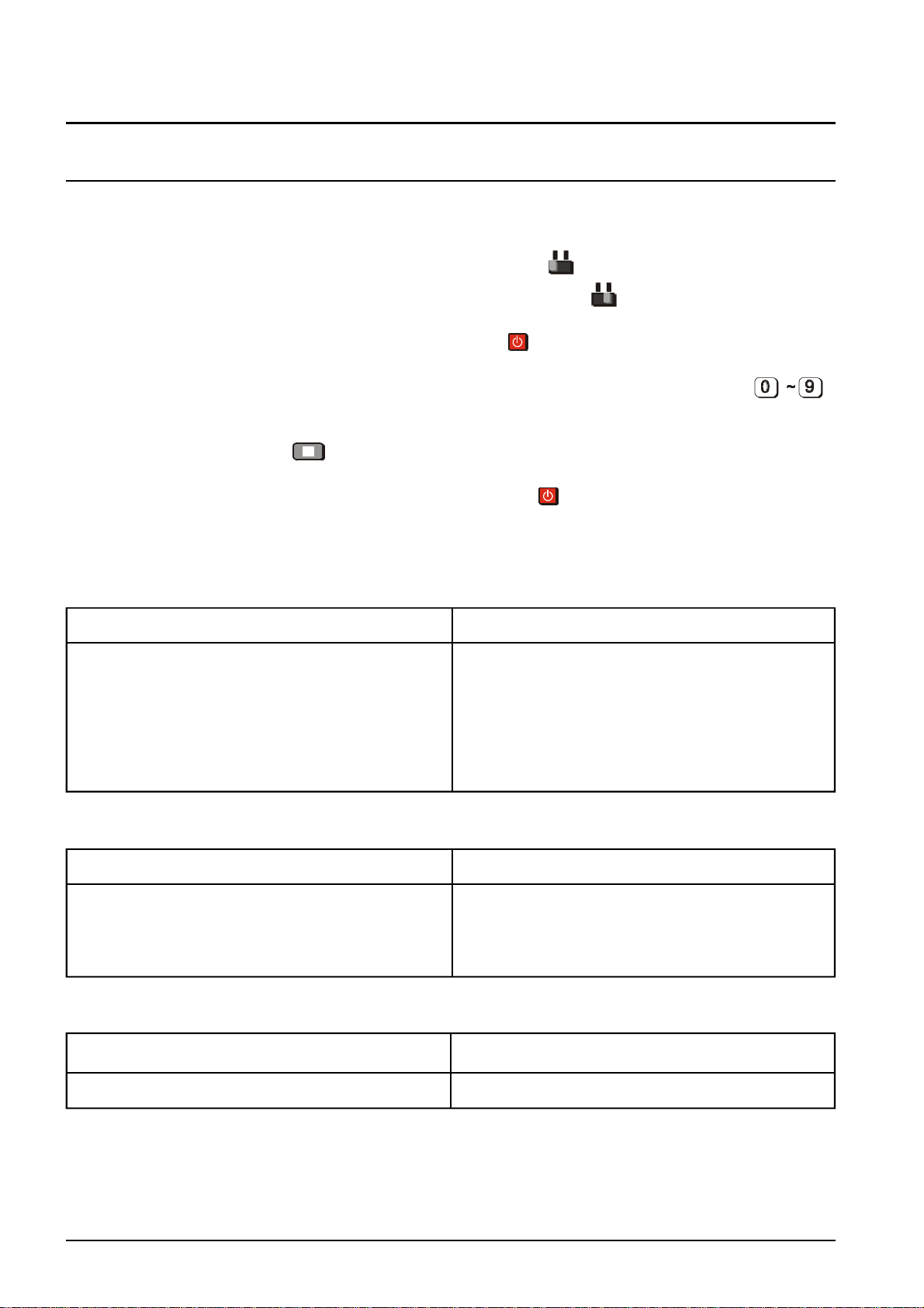
Remote Control VCR/LD/DVD Operation
Manufacturers’ Code Settings
This remote control has been designed to work with a variety of VCRs, Laser Disc players and DVD players.
In order for this to occur, the setting for the VCR, LD or DVD must be programmed into the Remote Control.
1. To set a VCR, slide the remote control VCR-LD/DVD switch to VCR.
To set a LD or DVD, slide the remote control VCR-LD/DVD switch to LD/DVD.
2. Push the remote control VCR - LD/DVD Power Button and keep it Pushed.
3. Enter the Manufacturer’s two-digit code number using the remote control Number Buttons
(The codes are shown below).
4. Push the STOP button .
5. Release the remote control VCR or LD/DVD Power Button .
6. Check the operation of the VCR, LD or DVD. If it does not operate correctly, repeat steps 1 to 5 and
use an alternate code (if there is one).
VCR CODES
Manufacturer Code Manufacturer Code
Panasonic / 10, 11, 12, 13 NEC 40, 41, 42, 43
National ORION 45, 46
AIWA 15, 16 Philips 50
FUJITSU 20 SANYO 55, 56, 57, 58
HITACHI 25, 26, 27 SHARP 60, 61
JVC 30, 31, 32 SONY 65, 66, 67
MITSUBISHI 35, 36 TOSHIBA 70, 71
LD CODES
Manufacturer Code Manufacturer Code
Panasonic 10, 11, 12, 13 SAMSUNG 30
KENWOOD 15, 16 SHARP 35
PHILIPS 20 SONY 40, 41, 42, 43
PIONEER 25
DVD CODES
Manufacturer Code
Panasonic 70
NOTES:
1. If the batteries are removed from the remote control the Manufacturer’s codes are lost and must be
reprogrammed.
2. The list of manufacturer’s codes is given as a guideline only. Panasonic cannot guarantee that any
other manufacturer’s product will work with this remote control.
34
Page 35
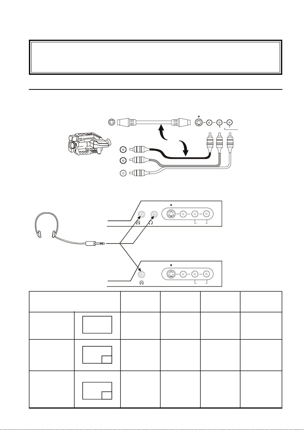
Connecting Equipment to the TV
*** NOTE ***
Headphones and connecting cables for Antennas, VCRs, LDs DVDs, Amplifiers and
Speakers etc. are not supplied with this television.
Front Panel Connections
The front input terminals allow quick and easy access for computer games, video cameras and other
equipment which is not usually permanently connected.
AV Equipment
Headphones
Headphones
(Not Supplied)
Stereo Plug
3.5mm
OR
S-VIDEO VIDEO
S-VIDEO VIDEO
L/MONO R
AUDIOMain Sub.
L/MONO R
AUDIO
AV3
IN
AV3
IN
TX-76PW10A
L/MONO R
AV3
S-VIDEO VIDEO
IN
AUDIO
TX-76PW05A
Screen Condition Speaker Main Sub Monitor
Sound Headphones Headphones Output
Single picture/ A A A A
Teletext (Stereo) (Stereo) (Stereo) (Stereo)
Picture in Picture A A B A
Picture in Picture B B A B
CHANGE (Stereo) (Stereo) (Mono) (Stereo)
A
A
B
B
A
(Stereo) (Stereo) (Mono) (Stereo)
35
Page 36
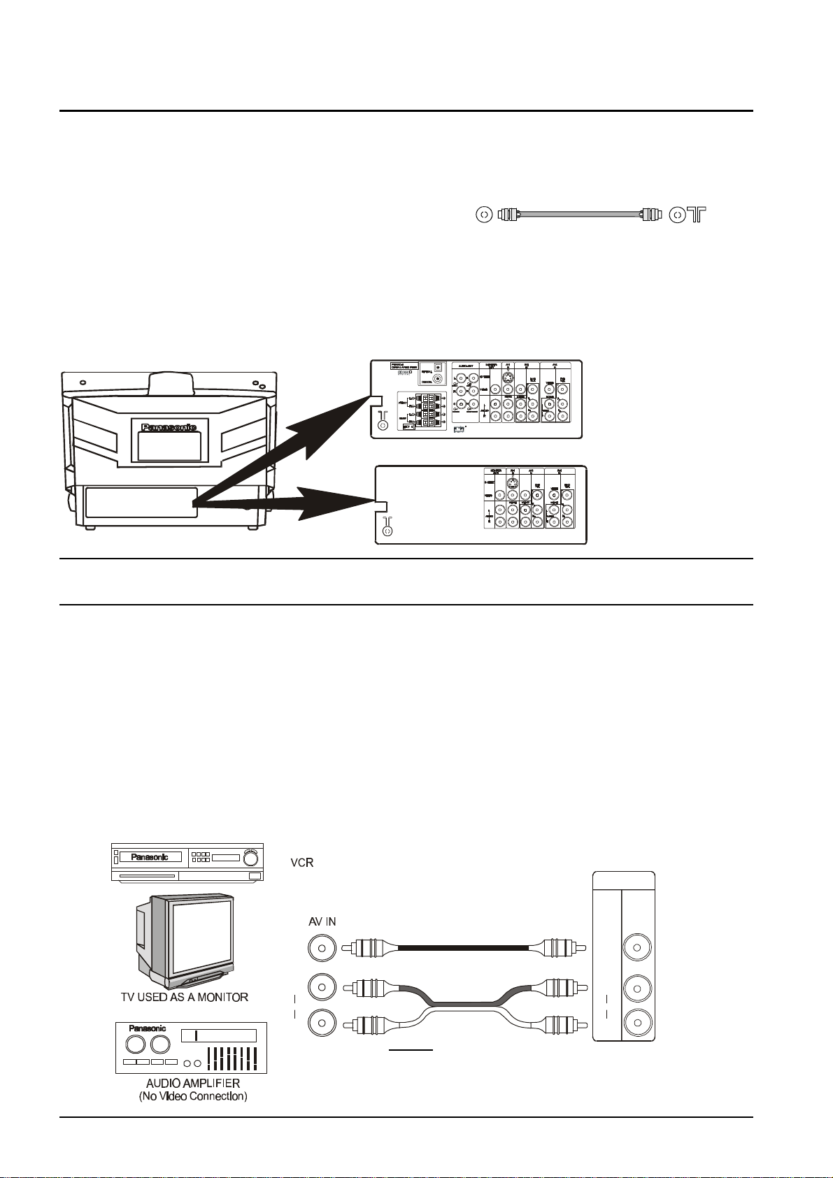
Connecting Equipment to the TV
Rear Panel Connections
When using a VCR with the television always connect the Aerial to the VCR and connect an RF Cable (not
supplied) between the VCR RF-Out and the television RF-In.
You can watch videos by either tuning the television to the
VCR (see page 30) or by connecting the VCR to the rear RF Cable
AV terminals.
Note: When connecting a mono VCR through the RF-In, please switch the TV to mono.
TX-76PW10A
TX-76PW05A
Monitor Out
The Monitor Out terminals reproduce the signals currently on the television screen. The on-screen signals
could be a television programme or signals connected to one of the AV inputs.
The Monitor Out facility can be used to allow one video source (videotape, video disc etc.) to be connected
to more than one television. Connect the Monitor out from this television to the AV Input of the second
television.
If a video recorder is connected to the Monitor Out and video sources (VCR, video disc, camera etc.) are
connected to one or more of the AV inputs, the television becomes a visual display for tape editing or
copying. Unauthorised recording of material from Television Broadcasts or from other video
and/or audio sources may contravene copyright laws.
The Monitor Out Audio can also be connected to a stereo amplifier or other hi-fi equipment.
MONITOR
OUT
36
VIDEO
AUDIO
VIDEO
L
R
L
AUDIO
R
NOTE:
Never connect the same video recorder or other device
to both the VIDEO IN and MONITOR OUT terminals of
this television as this could cause incorrect operation.
Page 37
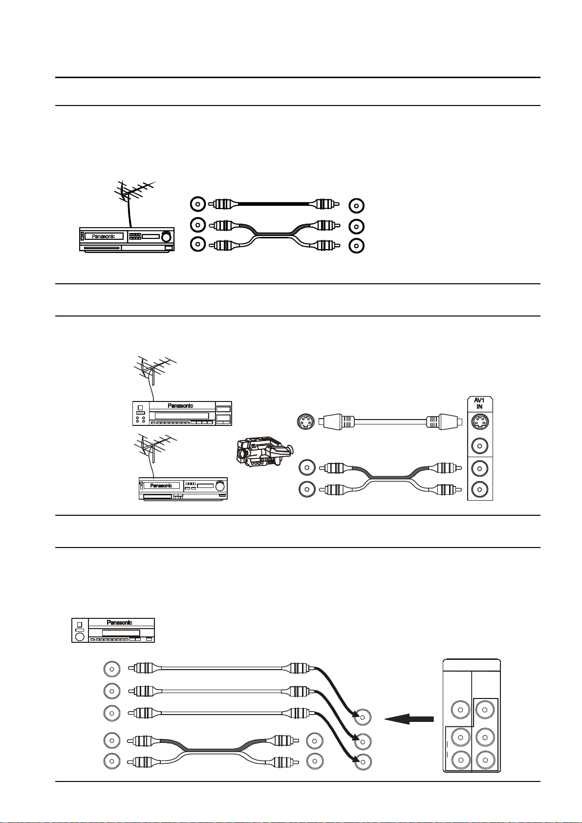
Connecting Equipment to the TV
Connecting a Standard VCR to the AV Input
Most standard Video Cassette Recorders use RCA type video and audio connectors. If your VCR has
different type connectors please refer to the VCR instruction book for details.
VCR AV1
OUT IN
VIDEO
NOTE: A mono VCR can be
connected to this television.
AUDIO Connect the VCR Audio out
to the Left Audio input on the
television. The sound will
Automatically be directed to both
STANDARD VCR speakers.
Connecting S-Video Equipment to the AV Input
S-Video equipment uses a 4Pin Mini Din (Male) plug for the video and RCA plugs for the audio. When an
S-Video cable is connected to an S-Video input terminal, the RCA video terminal for that AV position will be
disconnected.
Connecting DVD Equipment to the AV Input
The audio and video inputs on the television are RCA type connectors.
Connect the Y, PB and PR outputs from the DVD to the AV4 IN DVD Inputs on the television, as shown
below. Connect the “AUDIO OUT” to the AV4 IN AUDIO terminals on the television.
Note: Some DVD players only have an RCA “VIDEO OUT” terminal.
This can be connected to any of the VIDEO Inputs on the
television. Connect the “AUDIO OUT” to the corresponding
AUDIO terminals on the television.
MONO
L
R
AV4
IN
DVD
Y-P-P
Y
P
B
P
R
B R
L
AUDIO
R
VIDEO
MONO
AV4
IN
DVD
Y-P-P
B R
Y
P
B
P
R
DVD OUT
Y-P-P
B R
Y
P
B
P
R
AUDIO OUT
L
R
DVD PLAYER
37
Page 38
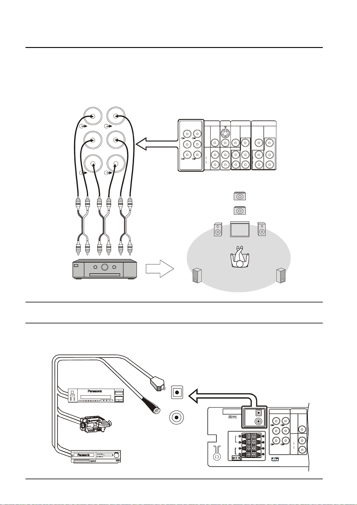
Optical Input
Connecting Equipment to the TV
Front
Connecting the Audio Out Terminals (TX-76PW10A only)
The Audio Out sockets on the rear of the TV allow you to create a custom sound system using an external
amplifier and external speakers.
You may decide, for example to use an external DTS/Dolby Digital amplifier to connect external left and right
front speakers, left and right rear surround speakers and a subwoofer (LFE speaker) as shown below.
L
FRONT
R
C
CENTRE
L
REAR
R
W
SUB WOOFER
Front
Centre Sub
DTS/Dolby Digital Amplifier
woofer
(L)(R) (R)(L)
Rear
Use Phono (RCA)
connectors.
To Speakers
AUDIO - OUT
L
FRONT REAR
R
C
CENTRE
MONITOR
OUT
S-VIDEO
L
VIDEO
R
W
L
AUDIO
SUB WOOFER
R
Subwoofer
Speaker
Left
Front
Speaker
Left Rear
Surround
Speaker
MONO
AV1
AV2
IN
IN
DVD
Y-P-P
Y
P
B
P
R
AV4
IN
DVD
L
AUDIO
R
VIDEO
MONOMONO
Y-P-P
B R
Y
P
B
P
R
B R
Centre
Speaker
Right
Speaker
Right
Rear
Surround
Speaker
Connecting the Digital Audio Input (TX-76PW10A only)
Additional equipment can be connected to the rear of the AV1/AV2/AV3/AV4 and via the two digital audio
input sockets (coaxial or optical)
Coaxial Input
Optical Input
OPTICAL
Camcorder
DVD Player
COAXIAL
PCM/AC-3
DIGITAL AUDIO INPUT
L
FRONT
R
L
REAR
R
EXT
OPTICAL
COAXIAL
AUDIO - OUT
L
FRONT
R
C
CENTRE SUB WOOFER
MONITOR
OUT
S-VIDEO
L
REAR
VIDEO
R
W
L
AUDIO
R
38
Page 39
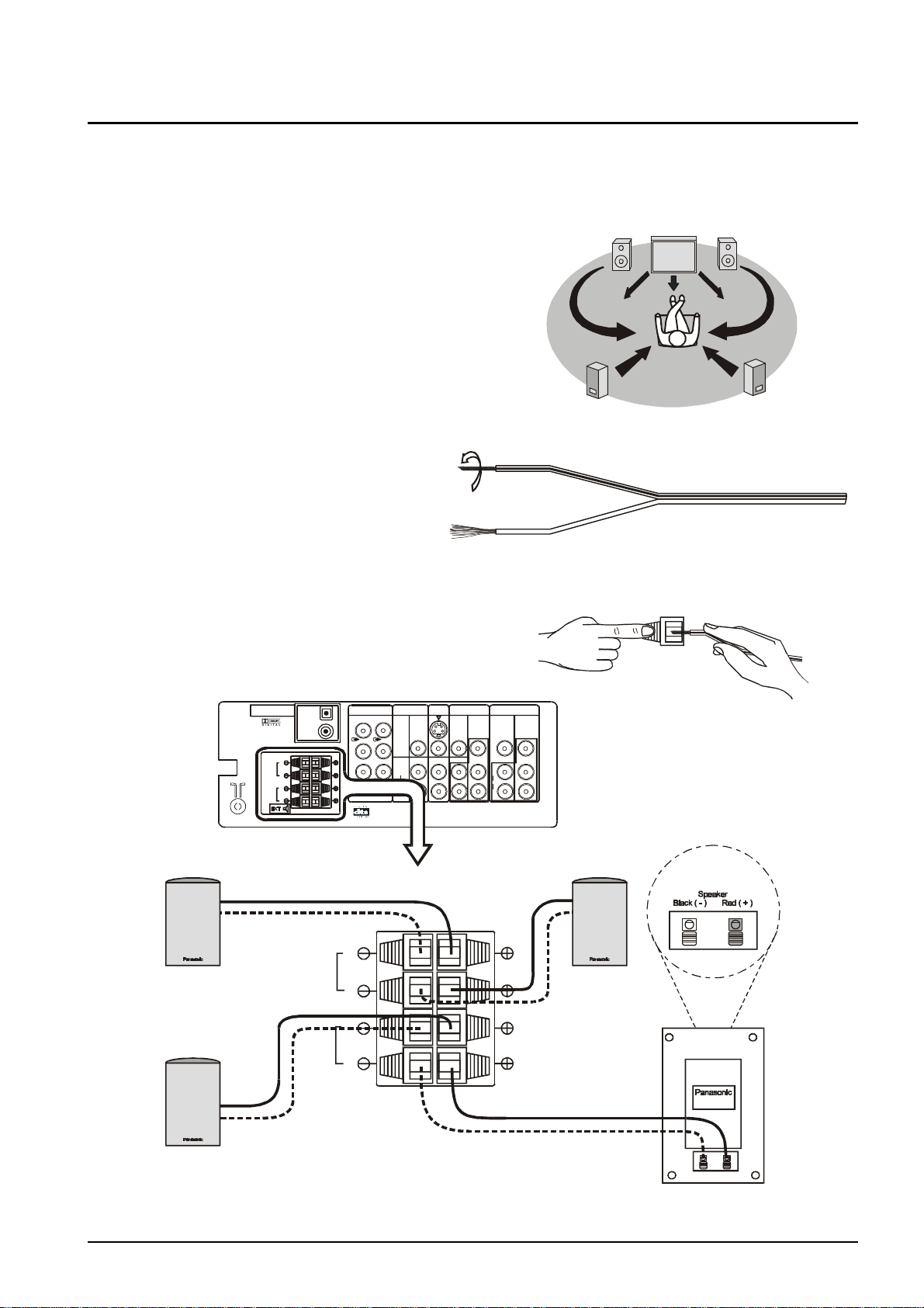
Left
Front
Connecting Equipment to the TV
Connecting the External Speakers (TX-76PW10A only)
The external speaker connections (EXT) on the rear of the TV allow you to create your own system using
external speakers.
Right
Front
You may decide, for example, to connect external left and
right front speakers and left and right rear surround
speakers as shown here.
The TV must be turned OFF before connecting external
equipment.
1. Twist the bare wire ends of the speaker
wires before inserting into the speaker
terminals.
Speaker
Left
Rear
Surround
Speaker
Speaker
Right
Surround
Speaker
Rear
2. Insert into terminals.
Ensure that bare speaker wires are not touching and
are fully inserted into the terminals.
PCM/AC-3
DIGITAL AUDIO INPUT
L
FRONT
R
L
REAR
R
EXT
OPTICAL
COAXIAL
L
FRONT
R
C
CENTRE SUB WOOFER
AUDIO - OUT
L
REAR
R
W
S-VIDEO
VIDEO
AUDIO
MONITOR
L
R
OUT
L
Left
Front
Speaker
FRONT
R
L
REAR
R
Push lever Insert Wire
AV1
AV2
IN
MONO
AV4
IN
IN
DVD
Y-P-P
Y
P
B
P
R
DVD
Y-P-P
L
AUDIO
R
B R
VIDEO
Y
MONOMONO
P
B
P
R
Right
Front
B R
Speaker
Left
Rear
Surround
Speaker
Right
Rear
Surround Speaker
39
Page 40
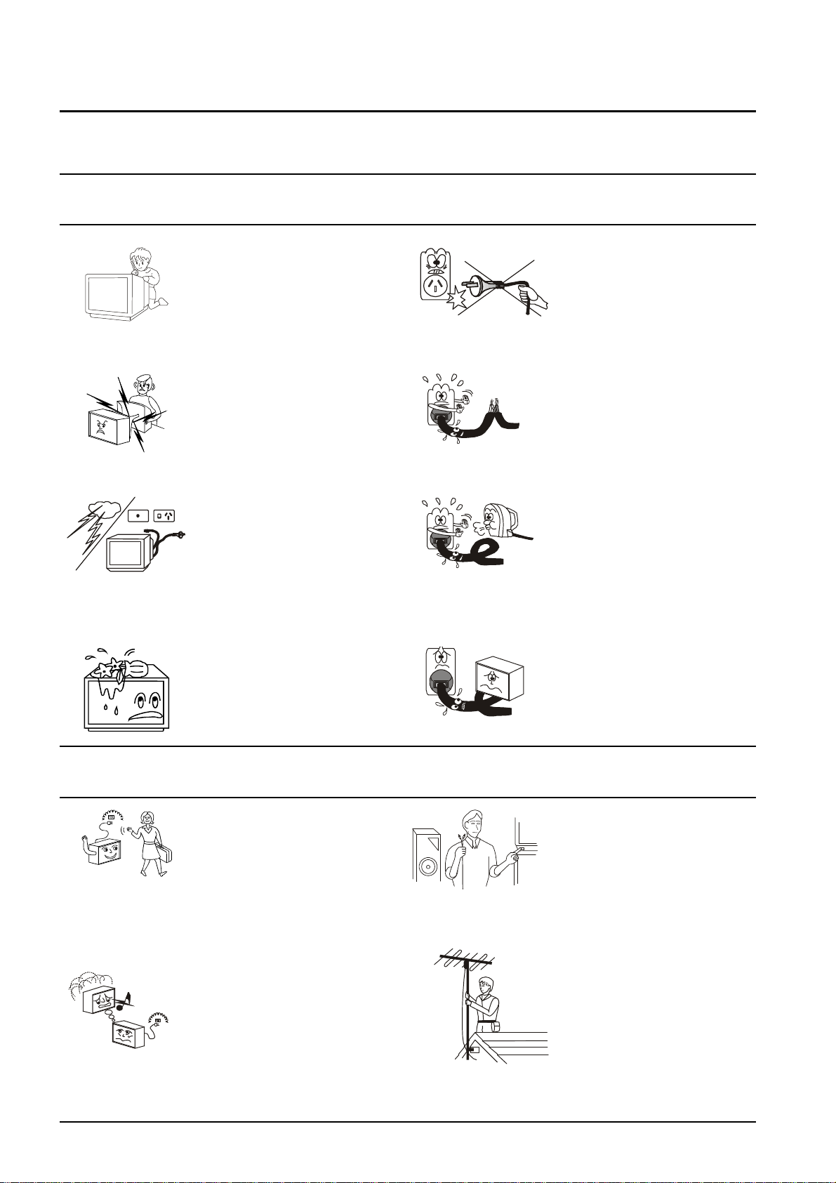
Customer Information
To keep your Panasonic Television in good working order please observe the following warnings and cautions.
Please be careful with this television. Like all electrical equipment it can cause serious injury or damage if it is
mistreated.
Warnings
Danger
Do not insert foreign objects.
(Keep metal or easily
inflammable objects out of this
television).
Danger: High Voltage
Do not remove the rear cover,
as High Voltage components will
be exposed.
DO NOT touch the aerial cable
and metal parts of the television
when there is lightning around.
During storms switch the
television off. DO NOT leave in
standby. Remove the plug from
the wall socket.
Do not place any containers of
water or other liquids on or near
this
television.
Danger
Always pull the plug out of the
wall outlet by holding the plug
itself.
Do not pull the plug by the
power cord.
Danger
Do not alter the power cord.
Do not use if the power cord
or plug is damaged or if the
plug does not fit tightly into
the socket.
Do not allow the power cord
to come into contact with
flame or hot surfaces.
Do not place heavy objects
on the power cord.
Cautions
Safety
First
40
Remove the Power Plug from the
wall socket when the Television
is not going to be used for an
extended period of time.
In the advent of unusual
operation (e.g. odd sounds,
smoke or aromas), turn the
television Off and remove the
power cord from the wall socket.
Then call the Television Service
Centre: this may reduce the
possibility of expensive repair
costs.
Turn the power OFF before
connecting other electrical
equipment.
Any external aerial should be
installed by a reputable
qualified installer and should
comply with Australian
Standard AS1417.1.
Page 41
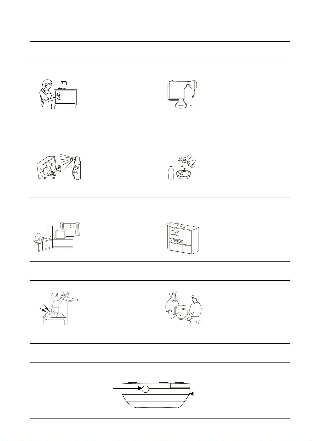
Customer Information
Cleaning the Television
Cabinet and Picture Tube Care
The cabinet and picture tube can
be kept in good condition by
wiping with a clean, lint free cloth
moistened with mild detergent
and water. For safety, remove
the plug from the power outlet
when cleaning.
Do not spray insecticide or
volatile solvent on the TV. Do
not allow rubber and vinyl
products to stay in contact with
the TV for long periods of time.
They may cause changes in
paint quality.
Locating the Television
Do not place the TV in humid or
dusty locations, or areas
exposed to smoke or steam.
Avoid exposing the television to
direct sunlight or any other
sources of direct heat.
This television contains many
plastic parts. For this reason Do
Not use benzene, thinners or
any solutions containing
petroleum or other chemicals.
Remove dirt and soiling by
wiping with a soft cloth. Even if
the television is heavily soiled
do not apply cleaner directly to
the unit. Soak a cloth in a
solution of neutral cleanser
thinned with water. Wring out
the cloth, wipe the television
clean and finish by wiping with a
dry cloth.
Adequate ventilation is
essential. Allow a gap of at least
10cm around the TV, even in a
cabinet or between shelves.
Caring for the Television
Do not subject the TV to any
physical shocks. Always remove
Do not stand or place heavy
objects on top of the television.
any connector cables when
moving the TV. When moving
the TV from one place to
another wrap it in something
protective.
Caring for the Remote Control
The lens of the Remote Control should be kept clean and free of dirt and grease. Use a soft cloth moistened
with water and a mild detergent to keep the lens clean.
Lens
Remote Control
41
Page 42
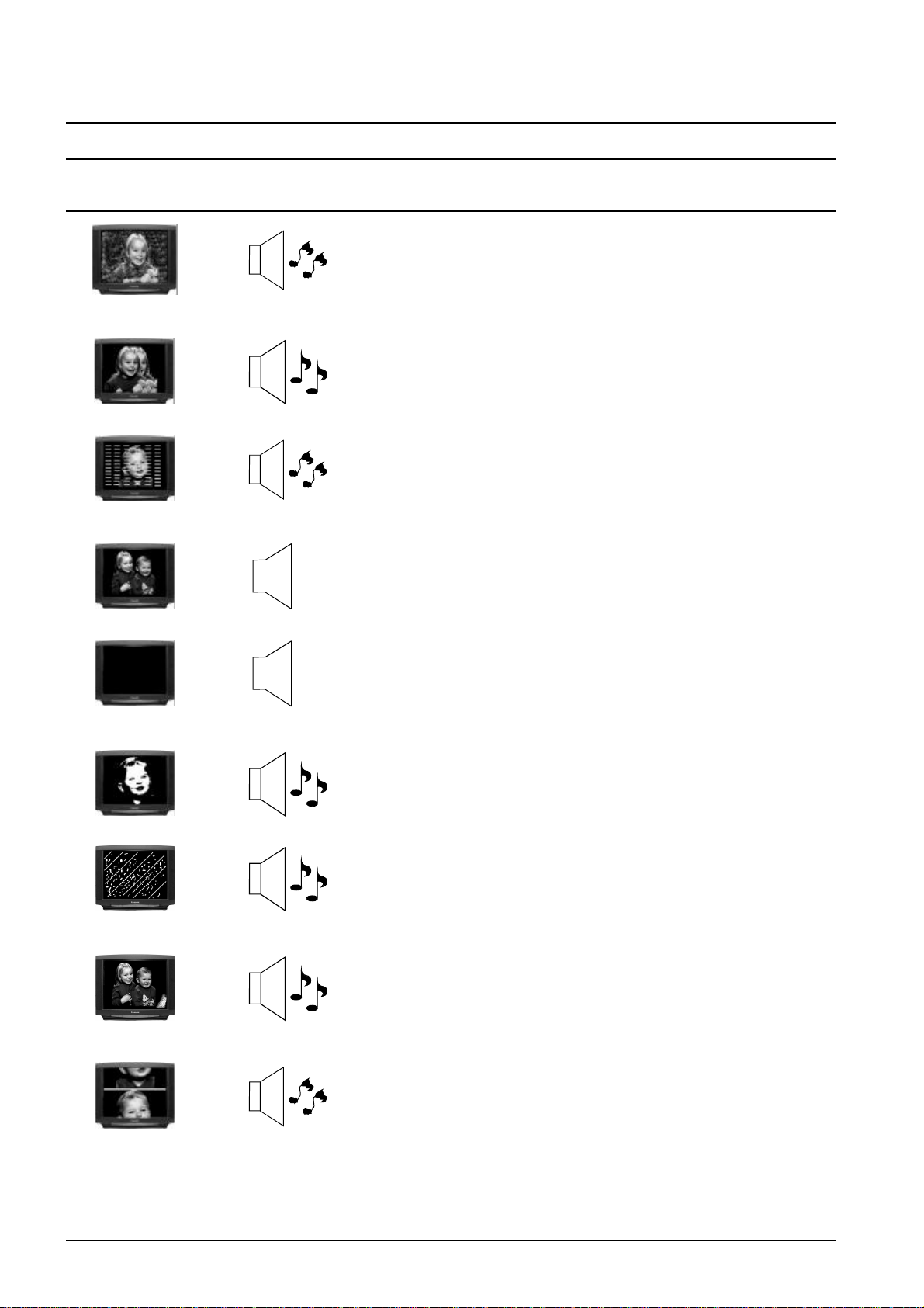
Troubleshooting
Before calling for service, determine the symptoms and make a few simple checks as shown below.
Picture Sound Check
Aerial Location, Direction or Connections.
If you are watching a tape playback check the state of the
Video heads – they may need to be cleaned or replaced.
The tape may be old. Check the tracking.
Snowy Picture Noisy Sound
Aerial Location, Direction or Connections.
Multiple Image Normal Sound
Electrical Appliances, Motorcycles, Cars or Fluorescent
Lamps.
Interference Noisy Sound
Normal Picture No Sound
No Picture No Sound
No Colour Normal Sound
Scrambled Normal or Weak Sound
Colour Patches Normal Sound
Volume (Check the Mute function)
Not plugged in, switched OFF or Set to Stand By. Check
volume, brightness, and contrast levels.
Various internal safety devices may have been triggered.
Switch the TV off for a few minutes and try again.
Colour Control.
If the picture is from a tape playback, try adjusting the
tracking.
Retune the Television. Refer to page 29.
Magnetic Interference from unshielded equipment or the
television may have been moved while it was switched ON.
(Switch the television OFF with the main power switch and
leave it OFF for about 30 minutes. Refer to page 31.
Rolling Picture Noisy Sound
42
Picture Menu (Refer to page 13).
Sound Menu (Refer to page 15).
Page 43
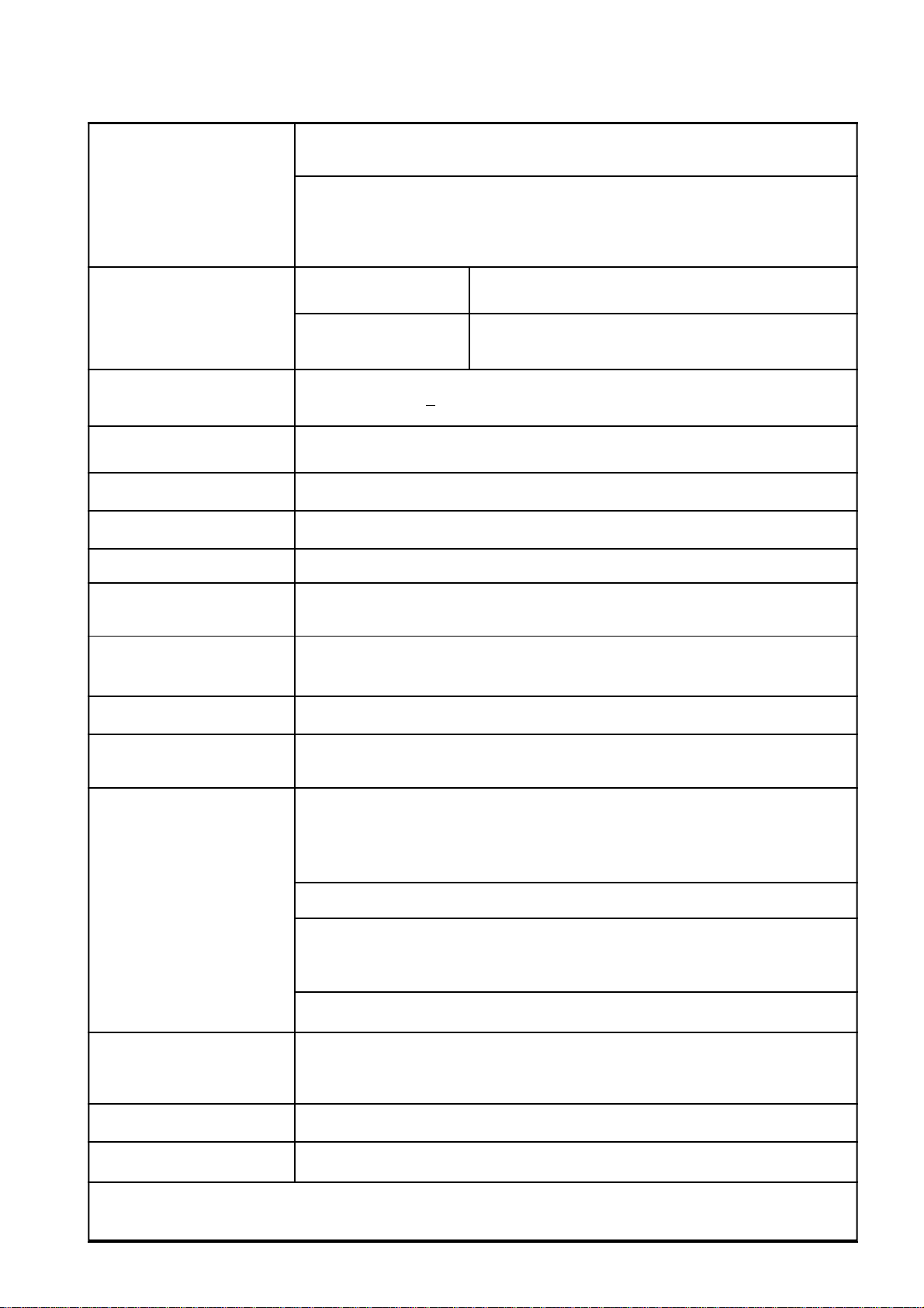
Specifications
Tuning System Frequency synthesized 100 Position ( 0 to 99 ).
RF Channels VHF 0 to 12 PAL B
UHF 21 to 69 PAL G
S’1 to S’3 HYPER TUNER
S1 to S41
Receiving Systems 1. PAL B/G Reception of Off air broadcasts
Playback from Video Tape Recorders
2. NTSC 4.43 Playback from Special Video Tape
3. NTSC 3.58 Recorders and Special Video Disc Players
4. PAL 60Hz (Via the AV Sockets) only.
Power Requirements 220 ~ 240Volts + 10% 50Hz
Power Consumption 211W Max 3W Stand-By
Chassis EURO7
Picture Tube 76cm Viewable (Measured diagonally)
Audio Output Two Way Four Speakers Plus AFB Woofer (10W + 10W + 12W)
External Speaker 10W x 4Speakers (Not supplied) TX-76PW10A
Connections
Headphone Socket 3.5mm Stereo (Main and Sub) TX-76PW10A
3.5mm Stereo (Main) TX-76PW05Z
Aerial Impedance 75Ω Unbalanced coaxial
Component Video 1080i and 576P TX-76PW10A
576P TX-76PW05A
Video / Audio Terminals AV1 IN (Rear) : S-Video, Video, Audio L/R Terminals
AV2 IN (Rear) : Video or Y/PB/PR, Audio L/R Terminals
AV3 IN (Front) : S-Video, Video, Audio L/R Terminals
AV4 IN (Rear) : Video or Y/PB/PR, Audio L/R Terminals
Digital Audio input coaxial, optical TX-76PW10A
Video / Audio Input S-Video Y : 1.0Vp-p 75Ω C: 0.3Vp-p 75Ω
Video in 1.0Vp-p, 75Ω
Audio in Approx. 400mV 1kΩ
Monitor Out Video Out 1.0Vp-p, 75Ω Audio Out Approx. 400mV 1kΩ
Accessories Supplied Remote Control EUR511226 TX-76PW10A
EUR511216 TX-76PW05A
2 Type ‘AA’ Batteries Instruction Manual TQB4A0145
Dimensions W = 77.7cm D = 53.53cm H = 61.13cm
Weight 60kg (Net)
Note:
Design and Specifications are subject to change without notice. Weight and Dimensions shown are approximate.
43
Page 44

Customer’s Record
The serial number of this product can be found on its rear cover and on the carton. It is recommended that
you note the serial number and other details in the space provided and retain this booklet in a safe place as a
permanent record of your purchase to aid in identification in the event of theft or loss.
Model No.
Serial No. PA Purchase Date
Purchased From
AUSTRALIA NEW ZEALAND
Panasonic
Customer
care
centre
132600
www.panasonic.com.au
Matsushita Electric Co. (Aust) Pty Ltd
P.O. Box 326 Penrith NSW 2751
ACN: 000 611 389
Certified to International Environmental Standard ISO14001
Certified to International Quality Standard AS/NZS ISO9001
Distributed in New Zealand by
Panasonic New Zealand Limited
350 Te Irirangi Drive
East Tamaki, Auckland
Customer Care Center
Ph: 0800 726 276
Email: [email protected]
www.panasonic.co.nz
Printed in Australia TQB4A0145
 Loading...