

Page 1
DP-CL18
ORDER No.KM60503633CE
G0
Color Laser Printer
© 2005 Panasonic Communications Co., Ltd. All
rights reserved. Unauthorized copying and
distribution is a violation of law.
Page 2
DP-CL18
2
Page 3

CONTENTS
Page Page
1 Introduction 5
1.1. Specifications
1.2. Options, Accessories and Supplies
1.3. Printer Panel
1.4. External View
1.5. Main Components Layout
1.6. PCB, Switches and Sensors Identification
2 About Lead Free Solder
2.1. Suggested PbF Solder
2.2. How to recognize that PbF Free solder is used
3 Installation, Setup, and Repacking
3.1. Installation Requirements
3.2. Setup
3.3. Repacking
4 User Mode Operation
4.1. User Mode Printer Panel Operation
4.2. User Mode Main Menu
4.3. Check then Print Selection 1 Menu
4.4. Memory Print Item Menu
4.5. Confidential Print Selection 1 Menu
4.6. System Information Item Menu
4.7. Color Calibration Item Menu
4.8. Maintenance Item Menu
4.9. Tray Item Menu
4.10. Print Item Menu
4.11. PCL Item Menu
4.12. PostScript Item Menu
4.13. N/W Protocol Setup Item Menu
4.14. Receive Setting Item Menu
4.15. Adjust to Media Item Menu
4.16. System Item Menu
4.17. Mono Page Detect Item Menu
5 HDD Maintenance Mode Operation
5.1. HDD Maintenance Mode Operation
5.2. HDD Maintenance Mode Menu Table
5.3. HDD Maintenance Mode Main Menu
5.4. HDD Information Item Menu
5.5. Check Disk Item Menu
5.6. Quick Format Item Menu
5.7. HDD Format Item Menu
5.8. HDD Deletion Item Menu
6 Service Mode Operation
6.1. Service Mode Control Panel Operation
6.2. Service Mode Menu Table
6.3. Service Main Menu
6.4. Print Report Item Menu
6.5. Position Setting Item Menu
6.6. STR Setting Item Menu
6.7. DEV. Bias Item Menu
6.8. FSR Temp. Setting Item Menu
6.9. Maintenance Item Menu
10
11
13
15
15
16
21
21
22
24
30
30
32
33
34
35
36
37
38
39
41
42
43
44
46
47
48
48
49
49
50
51
52
53
54
55
55
56
56
57
65
66
75
76
77
78
79
6.10. ENG Serial Number Item Menu
5
7
8
6.11. Controller Setting Item Menu
6.12. Panel Test Item Menu
6.13. Engine Test Item Menu
6.14. Color Correction Item Menu
6.15. Flag Setting Item Menu
6.16. Printing Network Configuration Report
7 Mechanical Function
7.1. Drive Mechanism General Description
7.2. Accumulator Tension Unit (ATU) Drive Mechanism
7.3. Print Process
8 Removal and Replacement Procedures
8.1. Fuser Unit
8.2. Accumulator Unit (Acc. Unit)
8.3. Front Door Cover and STR (Second Transfer Roller) Bias
Assembly
8.4. Right Cover
8.5. Rear, Left and Top Covers
8.6. Color Registration Sensor
8.7. Engine Control Board, Toner Cartridge Holder, Cartridge
Drive Unit, Paper Pickup Motor, Main Drive Unit, Bias Unit,
Fan Motor and Fan Motor Duct
8.8. LSU (Laser Scanning Unit)
8.9. Paper Exit
8.10. IH (Inductive Heater) Unit
8.11. Paper Feed Unit
8.12. Power Supply Unit (Power Supply Board and IH Power
Board)
8.13. Main Control Board
8.14. High Voltage Board and Reg. Thermistor Sensor
8.15. Accumulator Tension Unit
8.16. Print Cartridge Unit Holder
8.17. Fuser Fan Motor
8.18. Front Door Open Detection and Right Cover Open
Detection Switches
8.19. MPT (Multipurpose Print Tray) Home Position Sensor and
MPT Paper Detection Sensor Boards
8.20. Waste Toner Cartridge Full Sensor
8.21. Standard Paper Cassette
9 Block and Connection Diagrams
9.1. Block Diagram
9.2. Connection Diagram
10 Electrical Circuit General Description
10.1. General Description
10.2. Explanation of Connector
11 Adjustment
11.1. Print Position Calibration
11.2. Color Density Adjustment
11.3. Skew Adjustment
12 Preventative Maintenance
12.1. General
80
81
82
83
93
93
94
95
95
98
108
116
116
117
117
119
119
122
123
133
133
137
140
144
146
147
148
152
153
153
154
154
155
161
161
163
165
165
169
198
198
199
207
210
210
DP-CL18
3
Page 4

DP-CL18
12.2. Recommended Tools 210
12.3. Recommend Cleaning
12.4. Maintenance Tables
13 Tr oubleshooting
13.1. Initial Troubleshooting Flowchart
13.2. Warning/Error Message
13.3. Jam and HDD Error
13.4. Print Quality
13.5. Printer Error (Call Service)
13.6. No Message
13.7. No Printing
14 Replacemen t Parts List with Lubrication Guide
210
211
212
212
213
228
240
256
283
284
287
14.1. Covers
14.2. Left Side Parts
14.3. Right Side Parts
14.4. Front and Top Side Parts
14.5. Rear Side Parts (Power Supply, Main Control and High
Voltage Boards)
14.6. Cassette
14.7. Packing Material
14.8. Toner Cartridge Dummy Case
14.9. Print Cartridge Dummy Case
14.10. PbF Solder Service Part Number
287
290
297
301
307
310
313
313
313
314
4
Page 5
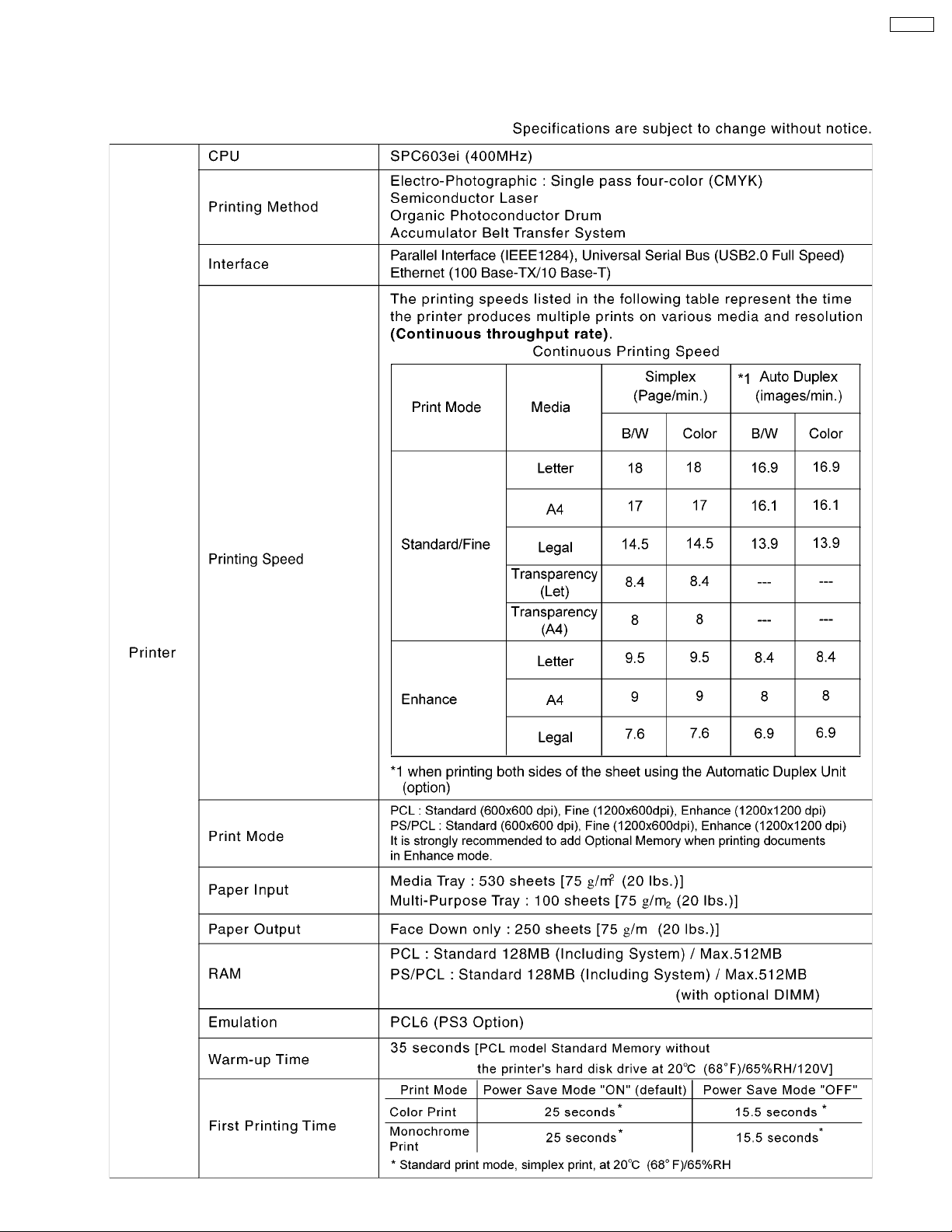
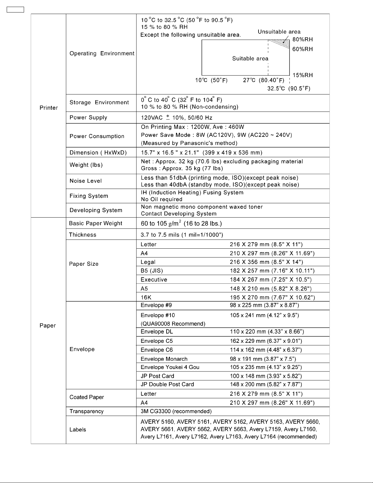
1 Introduction
1.1. Specifications
DP-CL18
5
Page 6
DP-CL18
6
Page 7
1.2. Options, Accessories and Supplies
Model No. Description Remarks
DQ-UR3K Black Toner Cartridge 6K Average Life (6,000 pages *1)
DQ-UR3C Cyan Toner Cartridge 6K Average Life (6,000 pages *1)
DQ-UR3M Magenta Toner Cartridge 6K Average Life (6,000 pages *1)
DQ-UR3Y Yellow Toner Cartridge 6K Average Life (6,000 pages *1)
DQ-UR4C Cyan Toner Cartridge 3K Average Life (3,000 pages *1)
DQ-UR4M Magenta Toner Cartridge 3K Average Life (3,000 pages *1)
DQ-UR4Y Yellow Toner Cartridge 3K Average Life (3,000 pages *1)
DQ-UP3K Black Print Cartridge Average Life (15,000 pages *1)
DQ-UP3C Color Print Cartridge Average Life (15,000 pages *1)
DQ-FU3 Fuser Unit Average Life (100,000 pages *1)
DQ-BF3 Waste Toner Cartridge Average Life (14,000 pages *1)
DQ-BE3 Accumulator Unit Average Life (100,000 pages *1)
DQ-BR3 Transfer Roller Average Life (100,000 pages *1)
DA-DS1 Optional Paper Feeder
KX-CLAD1 Automatic Duplex Unit
KX-CLEM3 128MB DIMM
KX-CLEM4 256MB DIMM
KX-CLHD2 Hard Disk Drive
DA-MC2 Upgrade Kit for DP-CL18 (PS3)
DP-CL18
*1
The rated life expectancy of each consumable is based on printing under specific operating conditions such as page coverage
for a particular page size (5% coverage per color at 600 x 600 dpi resolution on A4 size paper). The actual consumable life will
vary depending on its use and other printing variables including page coverage, page size, media type, print resolution,
continues or intermittent printing, number of color planes, ambient temperature and humidity.
7
Page 8
DP-CL18
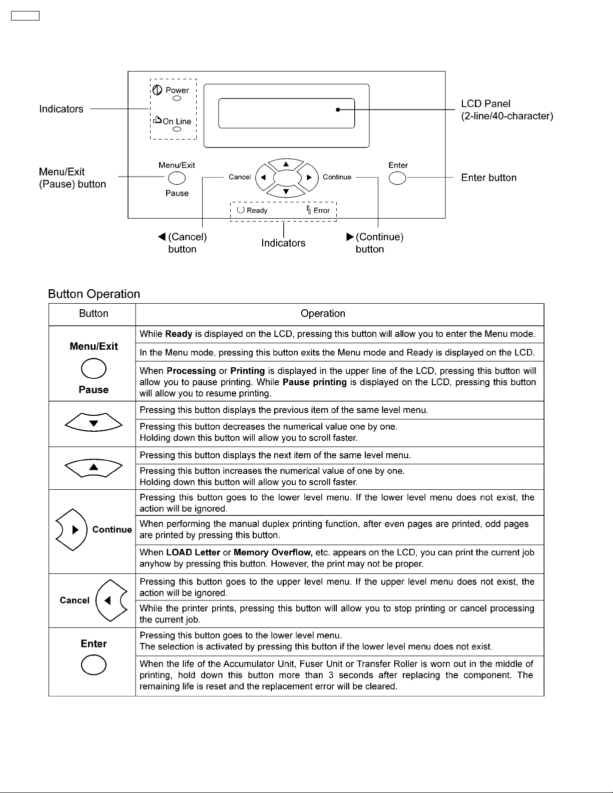
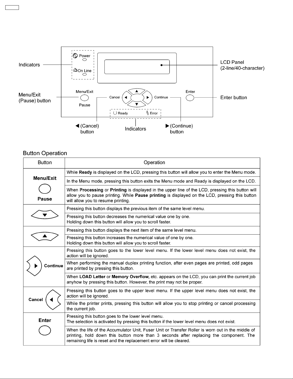
1.3. Printer Panel
1.3.1. Panel Operation
8
Page 9
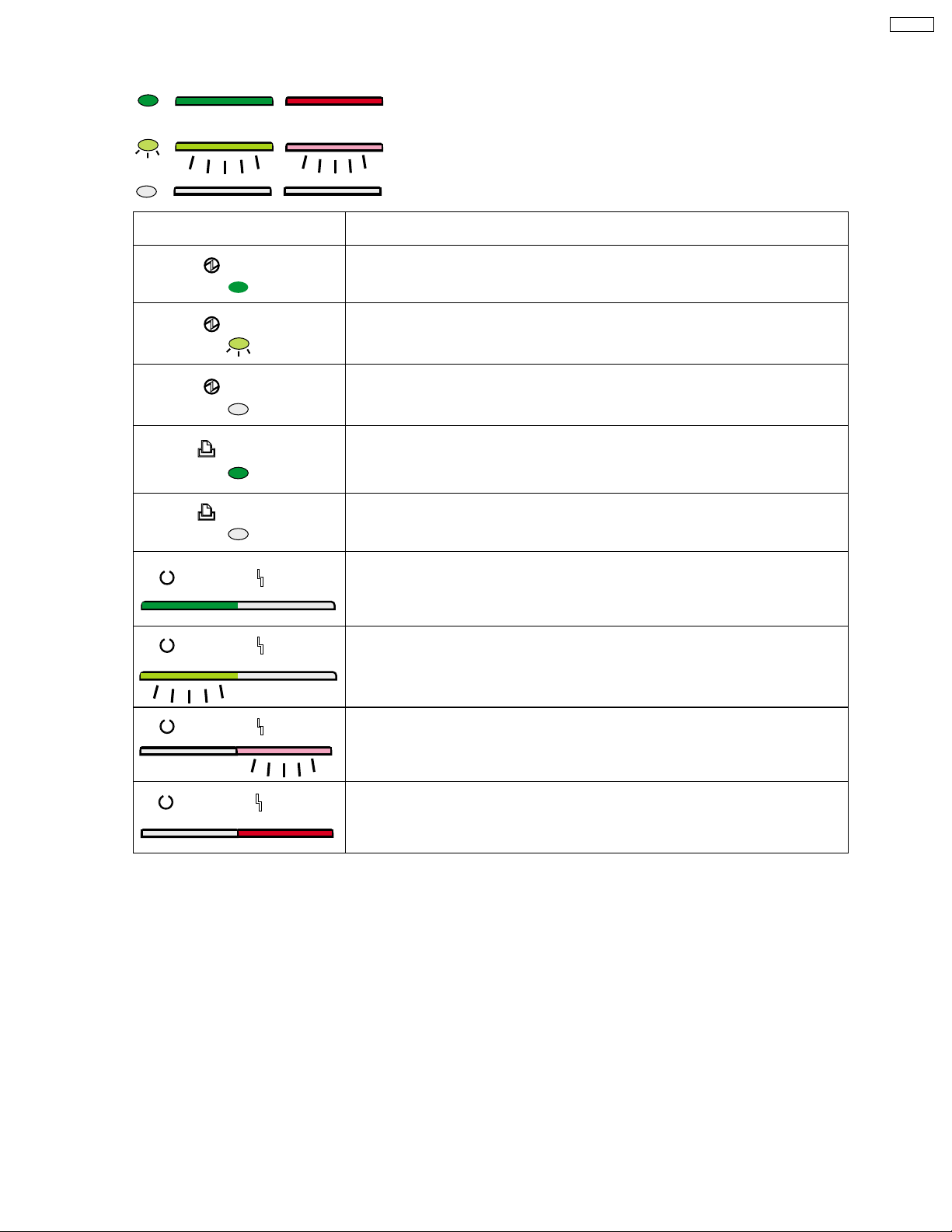
1.3.2. LED Indicator
Three indicators show the following printer’s status:
Indicator Printer Status
DP-CL18
On
Blink
Off
Power
Power
Power
On Line
On Line
Ready Error
Ready Error
Printer is turned on.
Printer is in the Power Save mode.
Printer is turned off.
Printer is ready for printing.
(Printer warms up and starts printing automatically
when it receives print data.)
Printer is in the Off Line.
Printer is in the normal condition.
Printer is not in error conditions.
Printer is receiving data, printing or data remains in the memory.
Printer is in the Menu mode.
Ready Error
Ready Error
Printer recoverable errors (media jam, media empty, etc.)
has occurred.
An internal error (Call for Service Error) has occured.
9
Page 10
DP-CL18
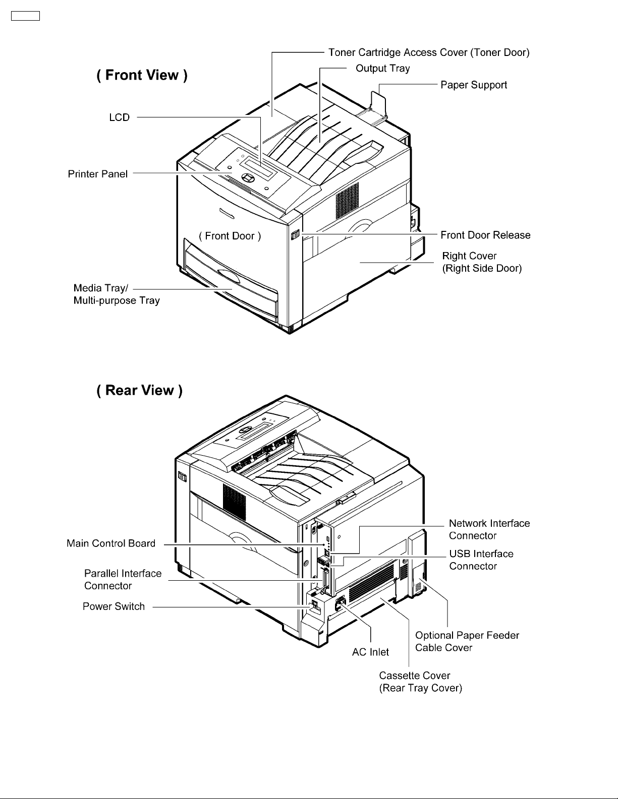
1.4. External View
10
Page 11
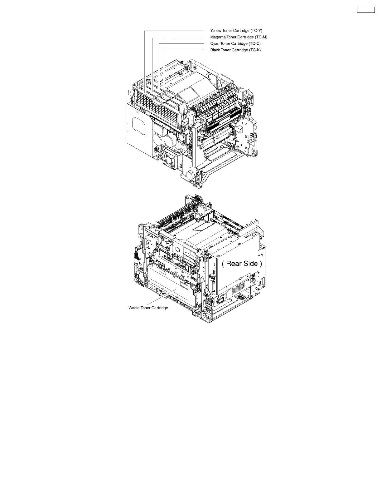
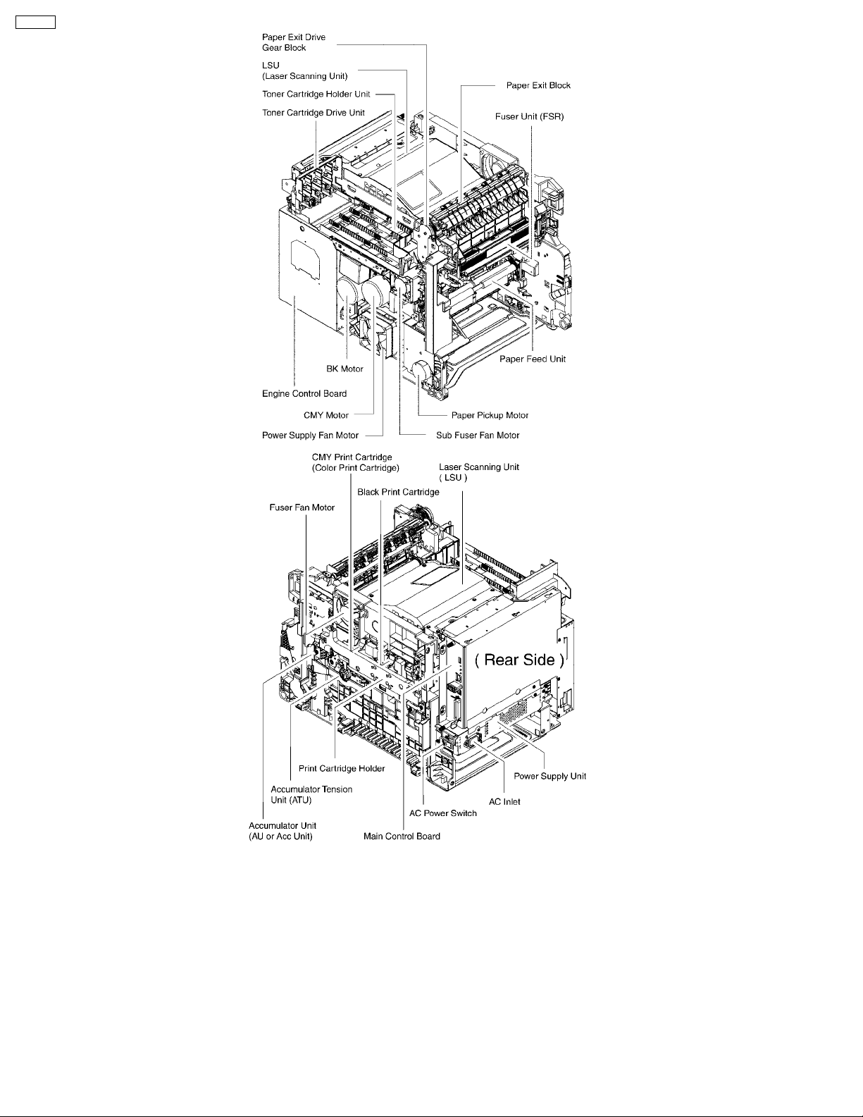
1.5. Main Components Layout
DP-CL18
11
Page 12
DP-CL18
12
Page 13
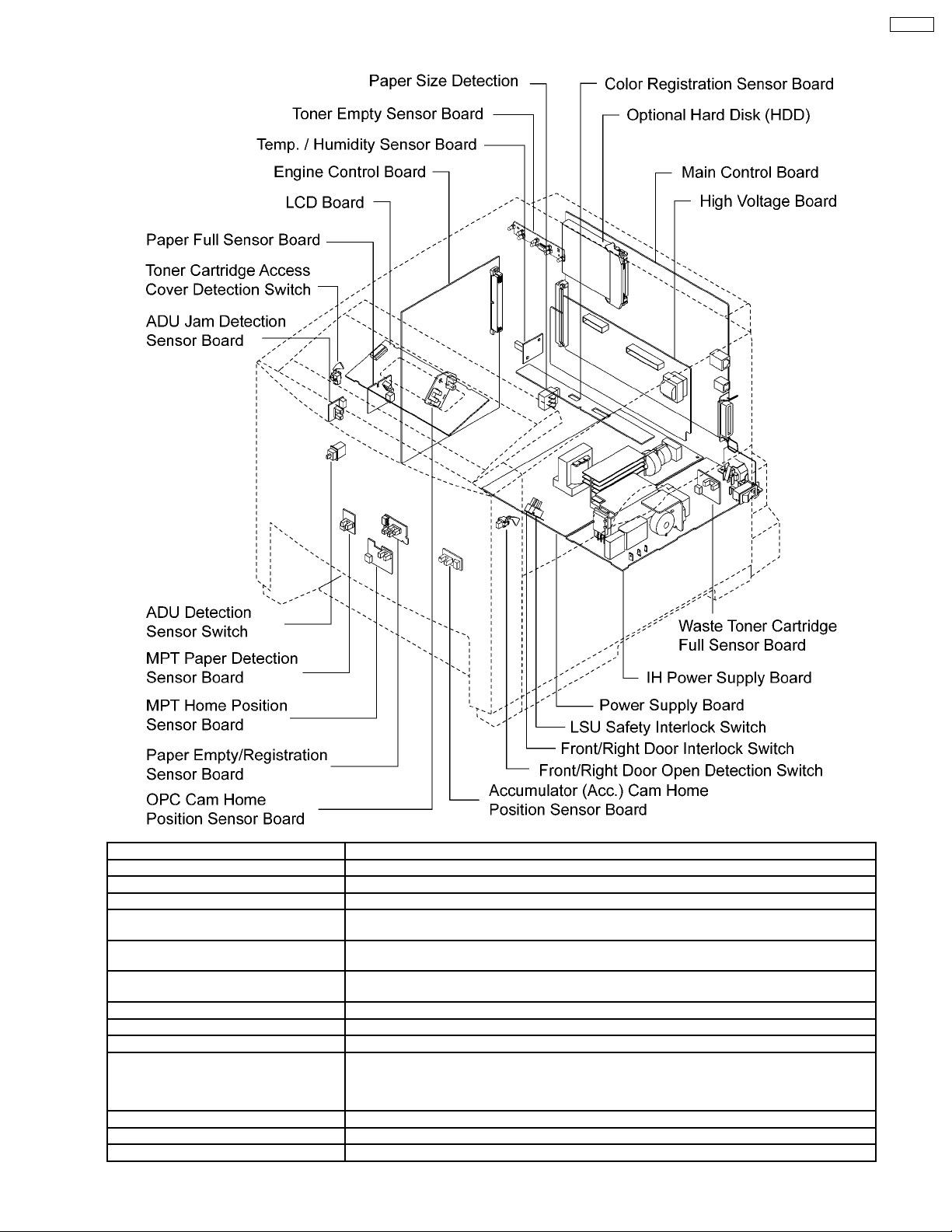
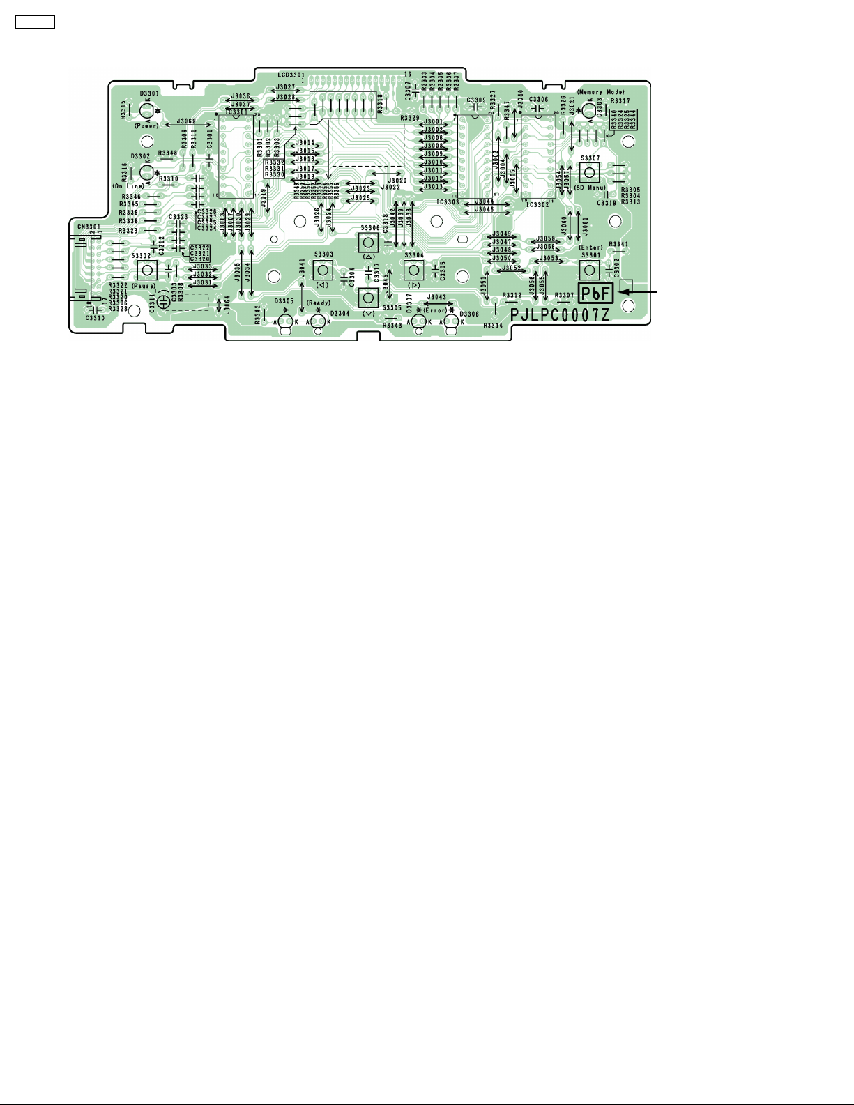
1.6. PCB, Switches and Sensors Identification
DP-CL18
Sensor/Switch/Board Name Description
Paper Size Detection For detecting the current selected paper size at the standard paper cassette.
Toner Empty Sensor Board For detecting whether the toner is low (or empty) or not.
Temp./Humidity Sensor Board For sensing the ambient temperature and humidity.
Paper Full Sensor Board This board has the paper full sensor. The paper full sensor is fo r detecting whether the output
Toner Cartridge Access Cover Detection
Switch
ADU Jam Detection Sensor Board For detecting whether the paper is ejected from the ADU (Option Automatic Duplex Unit) within
ADU Detection Sensor Switch For detecting whether the ADU is installed.
MPT Paper Detection Sensor Board For detecting whether the paper is set on the MPT (multi-purpose paper tray).
MPT Home Position Sensor Board For detecting the home position of the MPT pickup roller.
Paper Empty/Registration Sensor Board This board has the paper empty and registration sensors. The paper empty sensor is for
OPC Cam Home Position Sensor Board For detecting the home position of the OPC drum.
Acc. Cam Home Position Sensor Board For detecting the home position of the accumulator cam and controlling the printing process.
Front/Right Door Open Detection Switch For detecting whether the front door or right cover is opened.
paper tray is full.
For detecting whether the toner cartridge access cover is closed. If the toner cartridge access
cover is opened, printing is not possible.
the proper time.
detecting whether the paper is set on the standard paper cassette. The registration sensor is for
detecting whether the sheet of paper arrived at the registration roller after being properly picked
and traveling through the paper feed rollers.
13
Page 14

DP-CL18
Sensor/Switch/Board Name Description
LSU Safety Interlock Switch When the front door or right cover is opened (or both are opened), the power that is supplied to
the laser diode drive circuit in the laser unit is shut off because this switch is opened
Front/Right Door Interlock Switch When the front door or right cover is opened (or both are opened), the printing is not done
because this switch is opened.
Waste Toner Cartridge Full Sensor Board For detecting whether the waste toner cartridge is full.
Color Registration Sensor Board For reading the Color Registration Check Pattern to calculate adjustment for the fine Color
Registration Adjustment.
14
Page 15
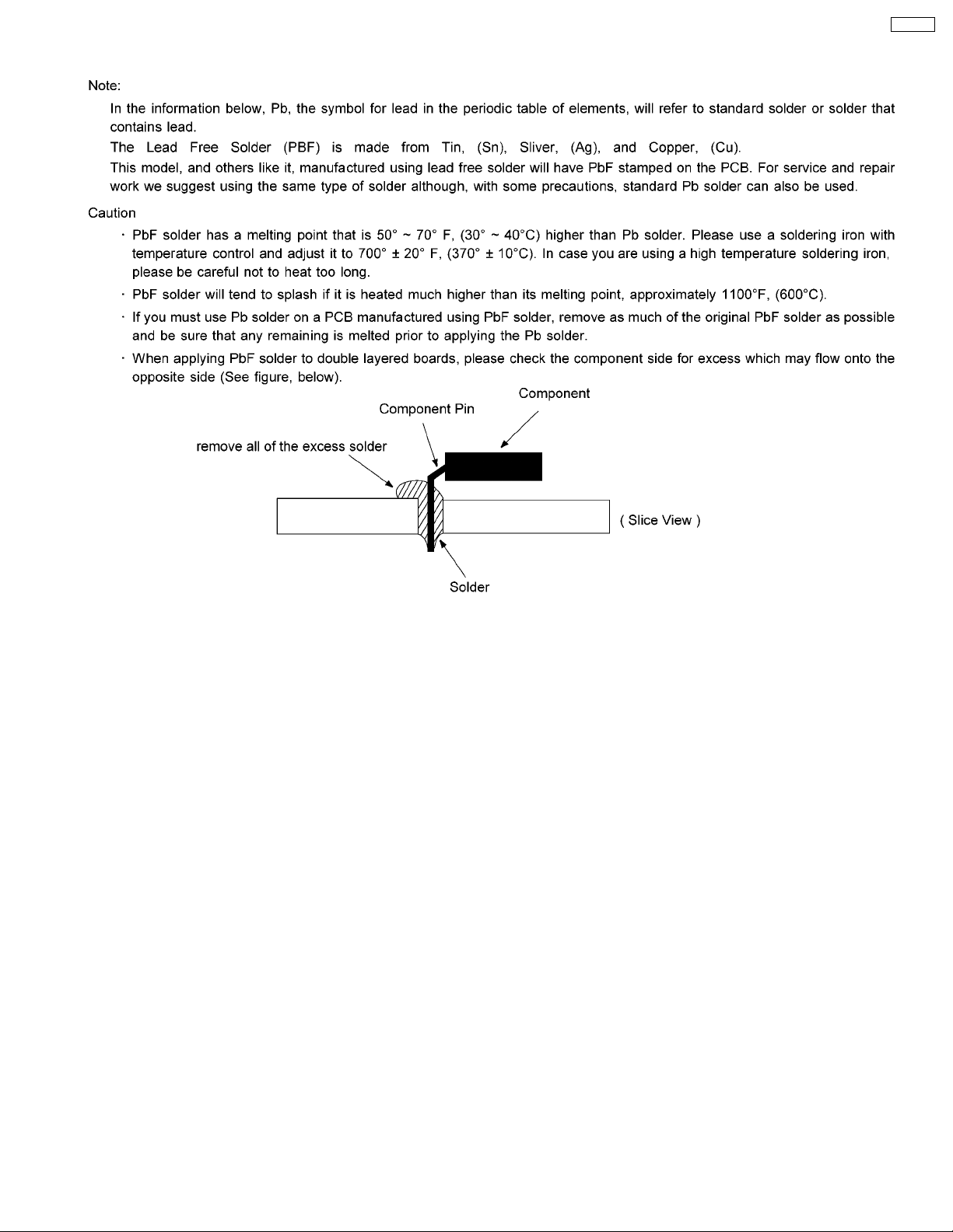
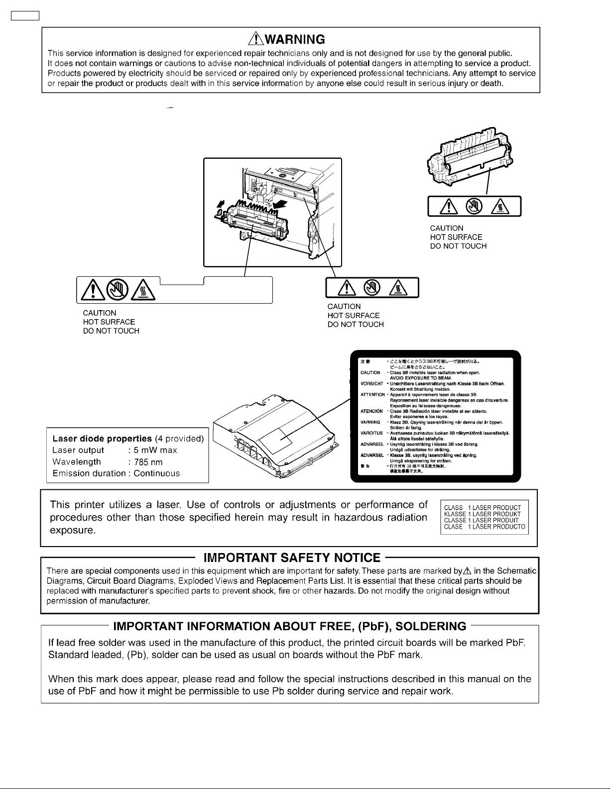
2 About Lead Free Solder
DP-CL18
2.1. Suggested PbF Solder
We recommend you to use the following solder when re-soldering component for repair. Before using other Pb free solder than the
following solder, be sure to confirm a solder maker you appoint has made license agreements to be required when using Pb free
solder legally.
Supplier: Senju Metal Industry Co., Ltd. (http://www.senju-m.co.jp)
Part Description in Senju: ECO SOLDER RMA02 P3 M705 Series
Note:
When the recommended PbF solder is not available at Senju Metal Industry Co., Ltd., see section 14.10 PbF Solder Service
Part Number.
15
Page 16
DP-CL18
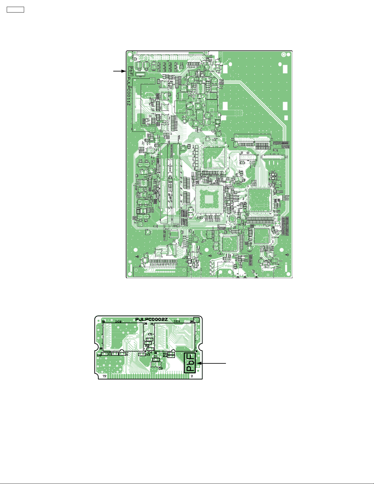
2.2. How to recognize that PbF Free solder is used
2.2.1. Main Control Board
(Top View)
Marked PbF
2.2.2. ROM Board
(Top View)
Marked PbF
16
Page 17
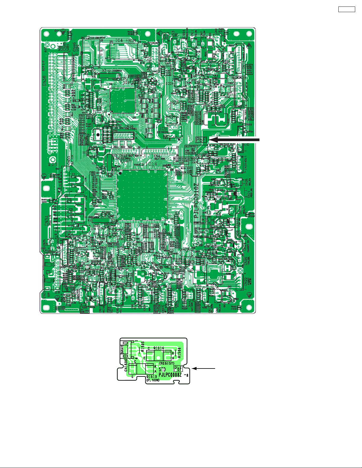
2.2.3. Engine Control Board
Marked PbF
DP-CL18
2.2.4. Paper Empty/Registration Sensor Board
17
Marked PbF
Page 18
DP-CL18
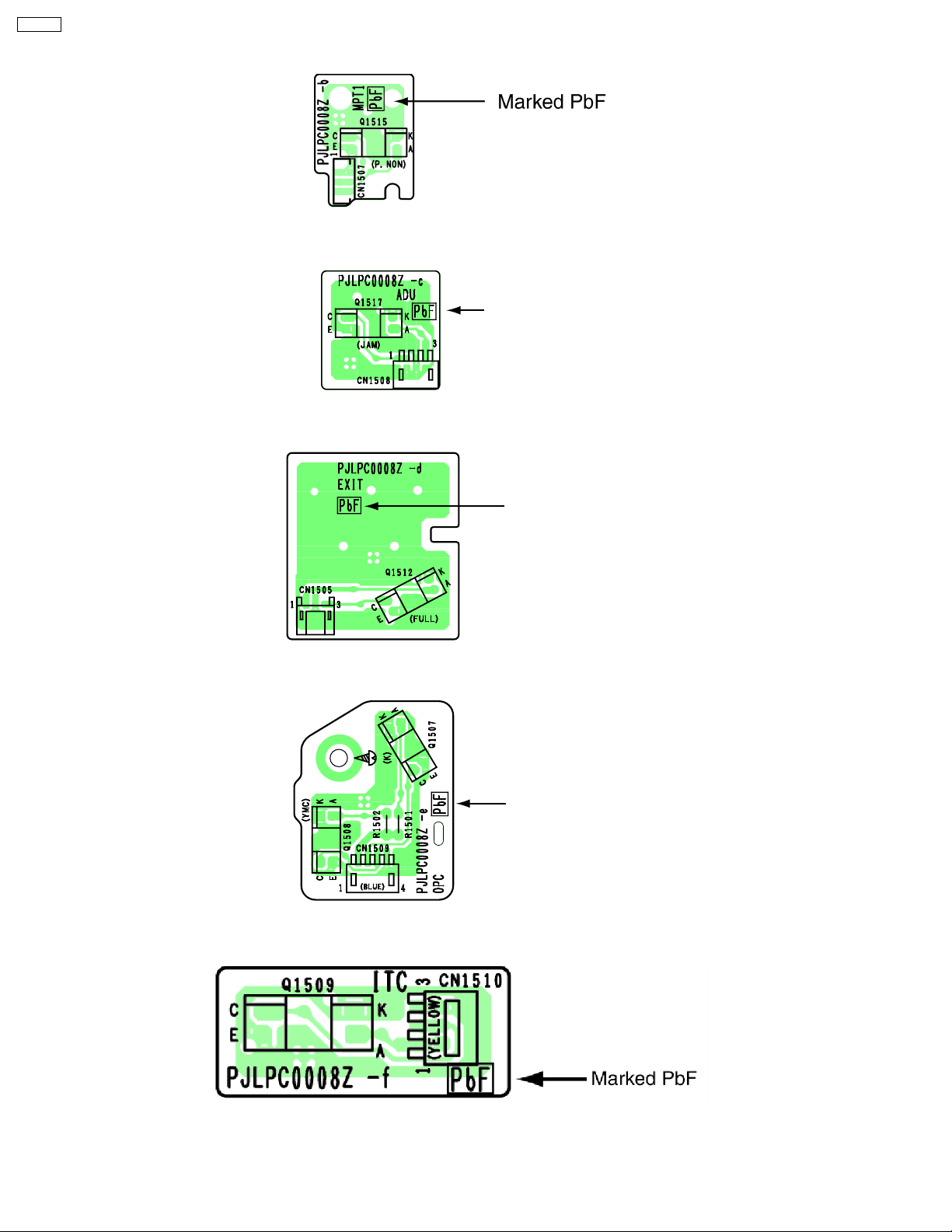
2.2.5. Multi-purpose (MPT) Paper Detection Sensor Board
2.2.6. ADU Jam Detection Sensor Board
Marked PbF
2.2.7. Paper Full Sensor Board
Marked PbF
2.2.8. OPC Cam Home Sensor Board
Marked PbF
2.2.9. Accumulator Cam Home Position Sensor Board
18
Page 19
2.2.10. Waste Toner Full Detection Board
Marked PbF
2.2.11. Toner Empty Sensor Board
Marked PbF
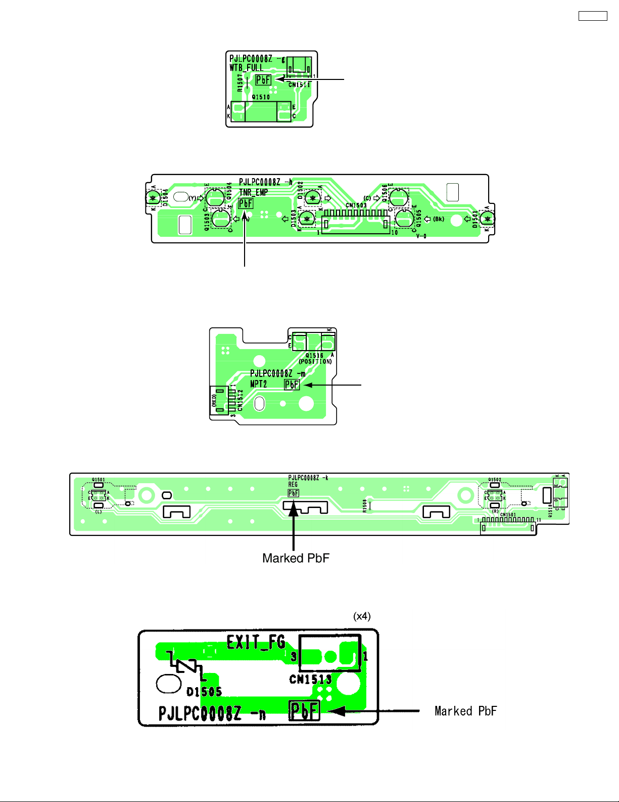
2.2.12. Multi-purpose (MPT) Home Position Sensor Board
DP-CL18
2.2.13. Color Registration Sensor Board
2.2.14. Exit FG Board
Marked PbF
19
Page 20
DP-CL18
2.2.15. LCD Board
Marked PbF
20
Page 21
3 Installation, Setup, and Repacking
3.1. Installation Requirements
3.1.1. Environment
1. Temperature Range :10 °C - 32.5 °C(50°F - 90.5 °F) (Temperature fluctuation ± 10 °C per hour or less)
2. Humidity Range :20% RH - 80% RH (Humidity fluctuation ± 20 °C per hour or less)
3. Weight : Gross; Approx. 33 kg (72.77 lbs.), Net; Approx. 30 kg (66.15 lbs) excluding packing material
4. Place the unit on a stable, level surface.
5. Do not install the unit under the following conditions.
a. Extremely high or low temperature
b. Extremely high or low humidity
c. Direct exposure to sunlight
d. Areas of high dust concentration
e. Areas of poor ventilation
f. Areas exposed to chemical fumes
g. Areas with extreme vibration
h. Directly in air conditioning flow
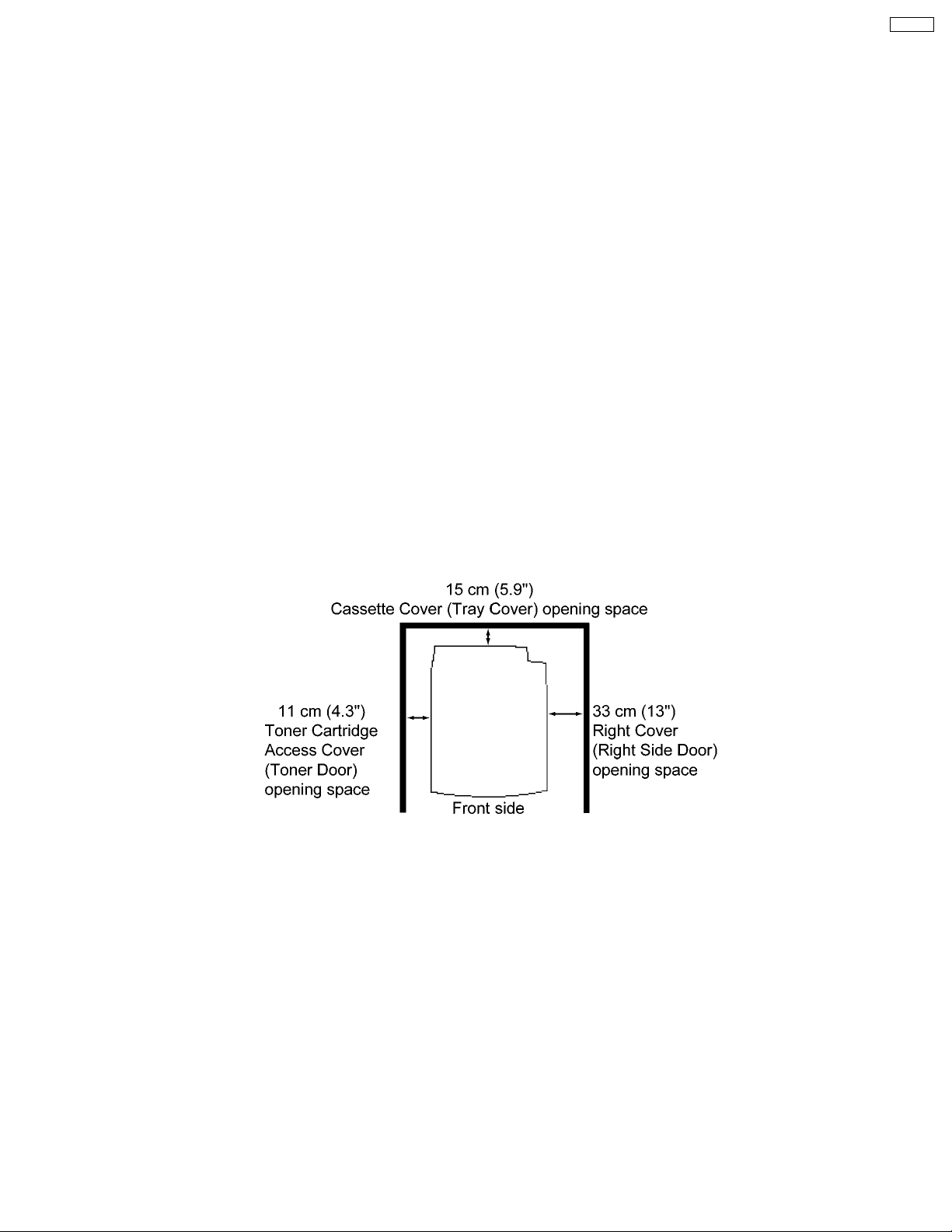
DP-CL18
3.1.2. Minimum Space Requirements
1. Right : 33 cm (13")
2. Left : 11 cm (4.3")
3. Rear : 15 cm (5.9")
Note:
When you install a consumable component or replace it with a new one, additional space may be required.
21
Page 22
DP-CL18
3.2. Setup
3.2.1. Removing the Packing Material
1. Remove the plastic bag from the printer.
2. Remove any adhesive tape.
Note:
Please do not throw away the packing materials. They may be required to ship or transport the printer. To provide optimum print
quality, the unit must be kept upright and level at all times.
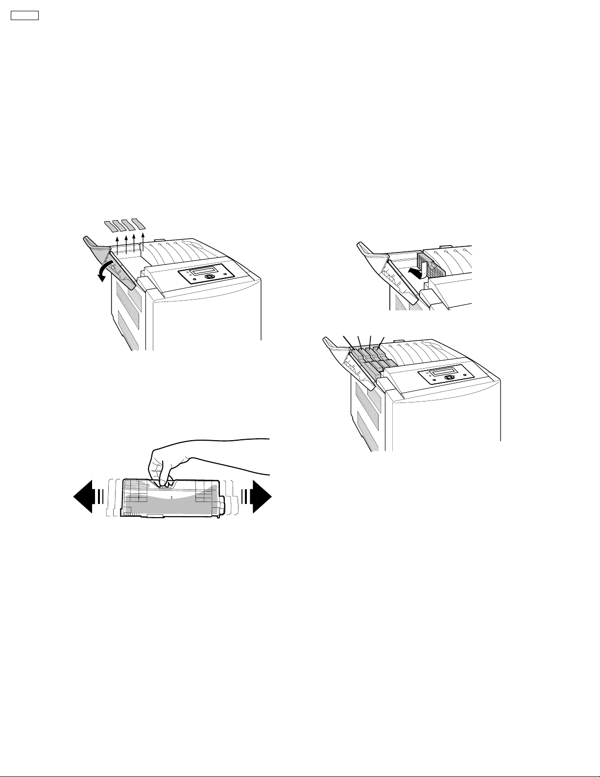
3.2.2. Installing the Toner Cartridge
1.Open the toner cartridge access cover
( toner door) and remove the sealing
tapes.
2.Open the plastic bags and take out the
toner cartridges. Shake the toner
cartridges several times.
3.Insert the toner cartridges in the appropriately
labeled slots. From right to left, the order of the
color toner cartridges is Black (1), Cyan (2),
Magenta (3), Yellow (4).
(4) (3) (2) (1)
4.Close the toner cartridge access cover ( toner
door).
22
Page 23
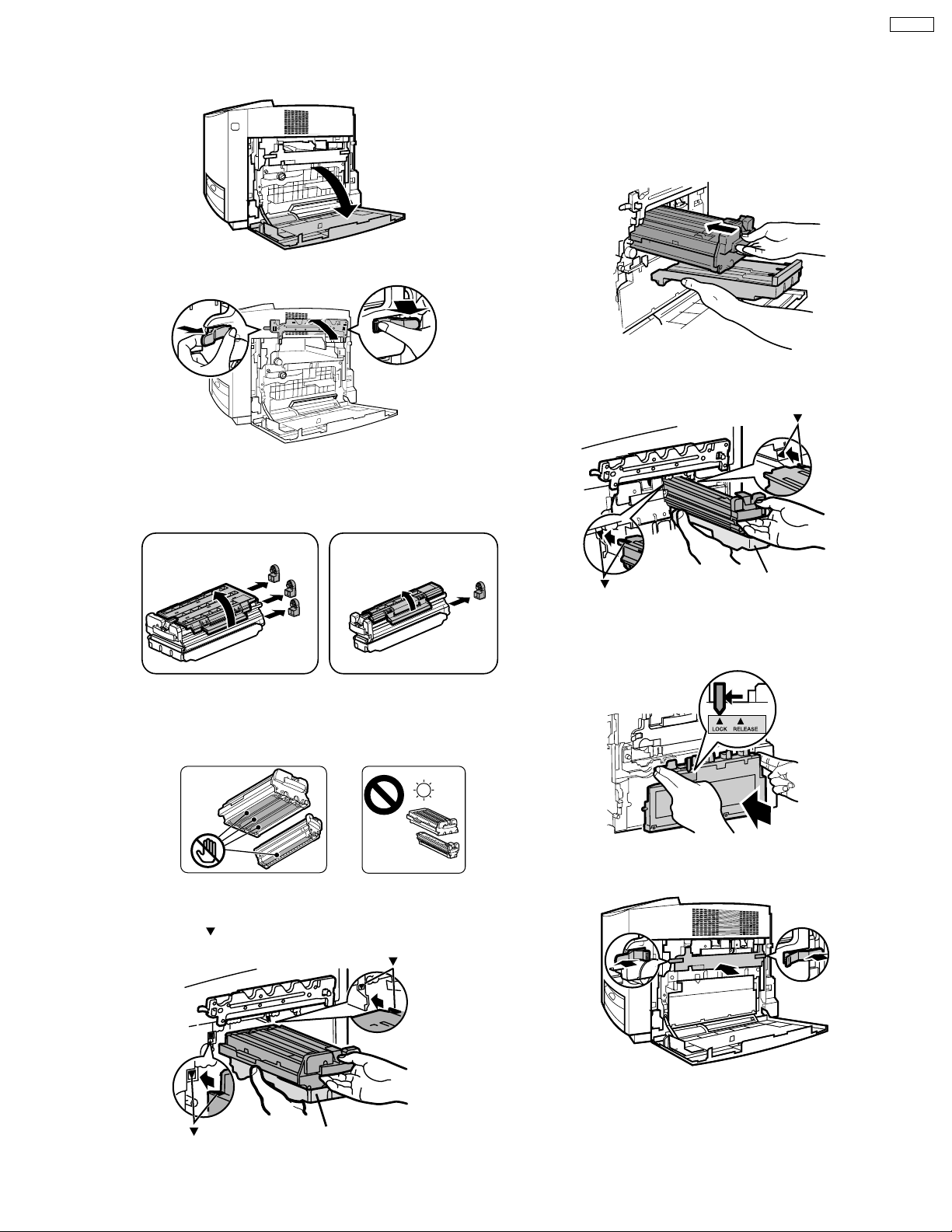
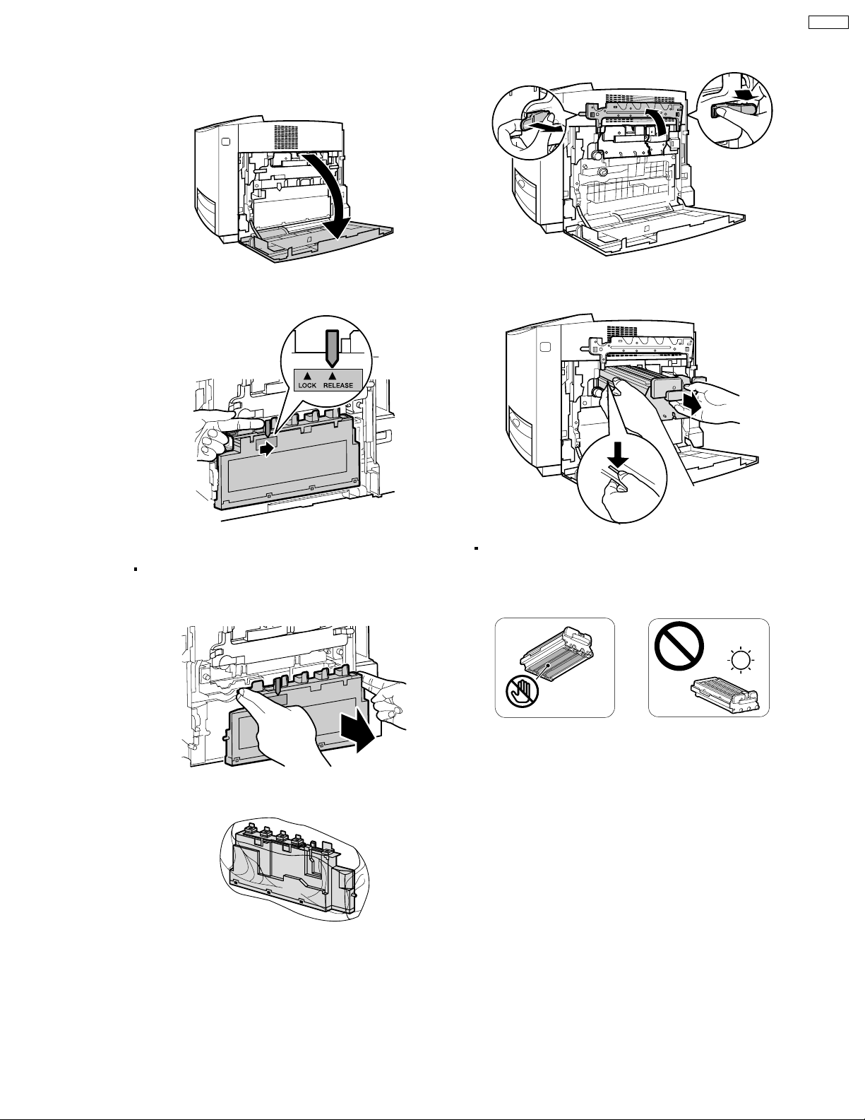
3.2.3. Installing the Print Cartridge
1.Open the right cover (right side door).
2.Unlock and open the print cartridge
holder.
Note:
To prevent damage to the print cartridge,
• Do not touch the green drum surface.
• Do not expose to light for more than 45 sec.
• Do not expose to direct sunlight.
4.Remove the seal covers.
5.Holding the color print cartridge with
the protective tray, match the arrow
marks ( ) then insert the color print
cartridge half way into the printer.
6.Firmly push the color print cartridge
until it snaps into place.
• Store the protective tray, seal covers,
packing materials and cartons for
repacking in future.
10.Close the right side cover (door).
3.Open the plastic bags and take out
the print cartridges.
Black print cartridge
Color print cartridge
Green
drum
Protective tray
( )
( )
7.Repeat steps 4 - 6 for the black print
cartridge.
( )
( )
Protective tray
1
2
9.Close the print cartridge holder until it
clicks (1) and locks it (2).
1
2
2
2
1
2
3
4
21
8.Install the waste toner cartridge (1)
and slide the green lever (2).
DP-CL18
23
Page 24

DP-CL18
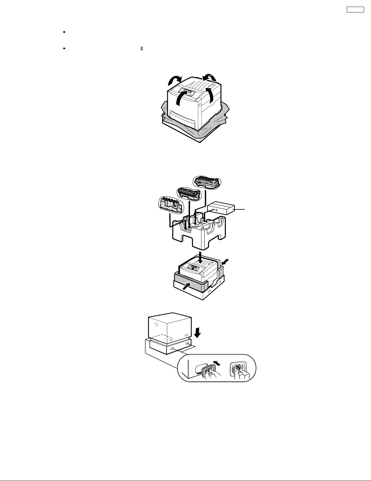
3.3. Repacking
Prepare the unit before shipping.
Note:
It is highly recommended that users keep the original carton and All packing materials. Please follow these instructions when
moving the printer.
· Please use the original carton and all of the original packing material.
· Improper repacking of the printer may result in a charge to repair the unit or a cleaning charge to remove spilled toner.
· Since the printer uses dry toner, extreme care must be taken when handling. The printer should be handled in the upright
(vertical) position.
· Original carton and packing materials
· Newspaper or drop cloth
· Shipping tape and scissors
24
Page 25
DP-CL18
1
Turn off the printer, remove the power code and all
interface cables.
2
Open the right cover (right side door).
3
Slide the green lever for the waste toner cartridge to
the right (RELEASE).
6
Unlock the two levers (1) and open the print
cartridge holder (2).
1
2
1
7
Pull out the color print cartridge halfway and remove
it (2) while pressing the green stopper (1) on the left
side.
2
1
4
Remove the waste toner cartridge.
Be sure the green lever is in the RELEASE position so
that upper openings to waste toner cartridge are
completely closed.
5
Insert the waste toner cartridge into a plastic bag
and seal the end of the bag tightly.
Note:
To prevent damage to the print cartridge;
- Do not touch the green drum surface.
- Do not expose to light for more than 45 minutes.
- Do not expose to direct sunlight.
25
Page 26
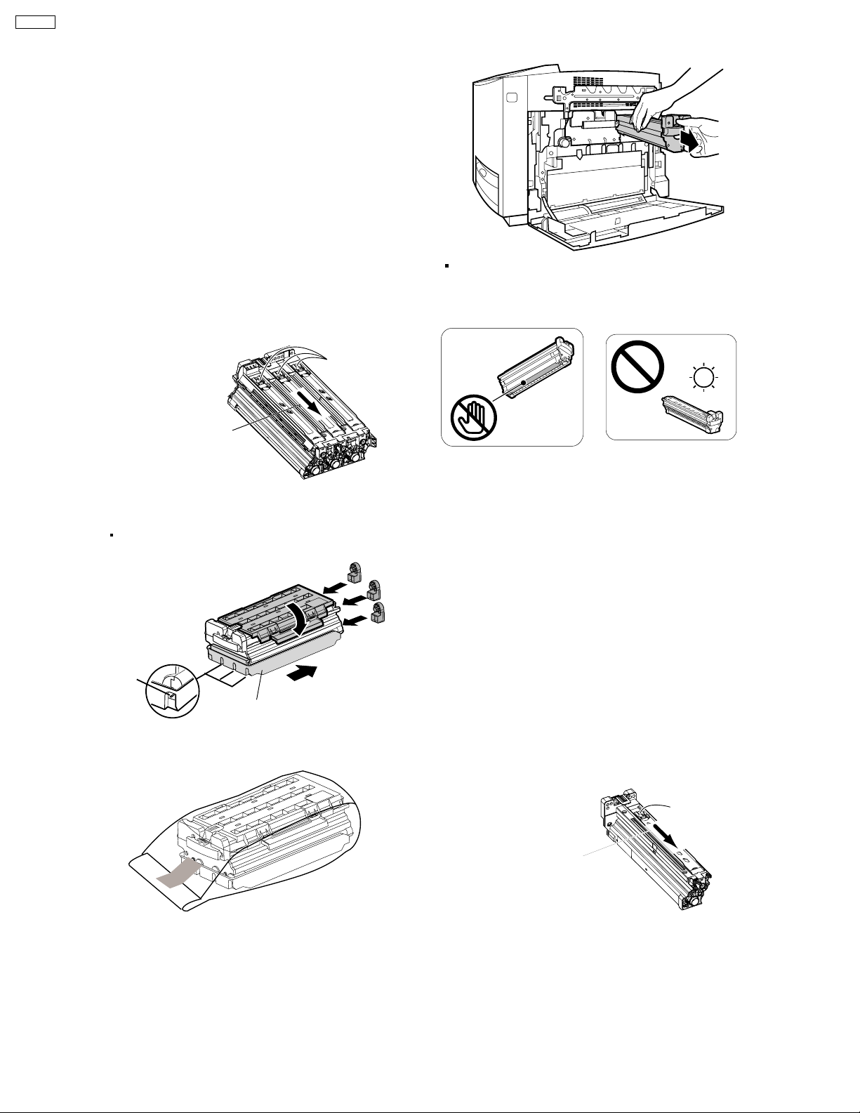
4
DP-CL18
8
Close the PC shutter and wipe off any loose toner on
the color print cartridge using a toner vacuum. Do not
use a standard office vacuum; the toner will not be
retained by typical vacuum dust collectors.
Caution 1:
If replacing the upper seal cover though the
toner is on the color print cartridge, the toner
will be scattered when removing the upper
seal cover. The scattered toner may be
attached to the OPC drum and the poor print
quality will be caused.
Caution 2:
If the print cartridge is wiped using a toner
vacuum when the PC shutter is opening, the
toner in the print cartridge is sucked and
charged. This charge is discharged to the
OPC drum and the OPC drum may be
damaged. Wipe off the toner on the print
cartridge using care that the PC shutter is
not opened.
Move the PC shutter in
this arrow direction to
close the PC shutter.
Replace the protective tray (1), upper seal covers (2-4)
9
and protective caps (5).
Be sure the three sealing levers of the print cartridge
are exposed through the lower seal cover.
PC Shutter
5
Lever
10
Insert the color print car tridge into the black plastic
bag and seal the end of the bag tightly with adhesive
tape.
1
Lower Seal Cover
11
Pull out the black print cartridge.
Note:
To prevent damage to the print cartridge;
- Do not touch the green drum surface.
- Do not expose to light for more than 45 minutes.
- Do not expose to direct sunlight.
12
Close the PC shutter and wipe off any loose toner on
the black print cartridge using a toner vacuum. Do
not use a standard office vacuum; the toner will not
be retained by typical vacuum dust collectors.
Caution 1:
If replacing the upper seal cover though the
2
3
4
Caution 2:
toner is on the black print cartridge, the toner
will be scattered when removing the upper
seal cover. The scattered toner may be
attached to the OPC drum and the poor print
quality will be caused.
If the print cartridge is wiped using a toner
vacuum when the PC shutter is opening, the
toner in the print cartridge is sucked and
charged. This charge is discharged to the
OPC drum and the OPC drum may be
damaged. Wipe off the toner on the print
cartridge using care that the PC shutter is
not opened.
26
PC Shutter
Move the PC shutter in
this arrow direction to
close the PC shutter.
Page 27
DP-CL18
13
Replace the protective tray (1), upper seal cover (2)
and protective cap (3).
Be sure the sealing lever of the print cartridge is
exposed through the lower seal cover .
32
Lever
Lower Seal Cover
14
Insert the black print cartridge into the black plastic
bag and seal the end of the bag tightly with
adhesive tape.
1
16
Remove the media from the multi-purpose tray.
Push the multi-purpose tray (1) and close the tray
cover (2).
1
2
17
Pull the media tray (1) out of the printer. Remove the
media (2) from the media tray and install the tray pad
(3) into the media tray.
15
Close the print cartridge holder [(1)-(2)] and lock it.
Close the right cover (3) (right side door).
11
22
33
Note:
Be sure the accumulator unit is kept in the printer.
22
Accumulator unit
3
1
18
Install the media tray into the printer.
19
Close (1) and insert (2) the paper support into the
printer.
2
1
2
20
Confirm all toner cartr idges are completely installed
in the printer.
27
Page 28
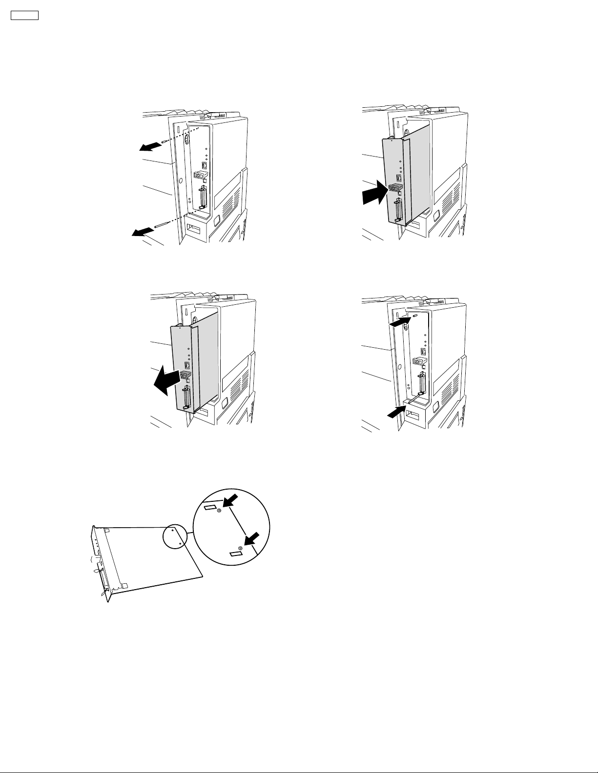
DP-CL18
If the hard disk drive option has been installed in the printer, confirm the hard disk
drive is fastened with two screws provided. If it is not installed, proceed to step 26.
21
Remove the two thumb screws from the main
control board.
22
Pull out the main control board while holding the
green handle.
Install the main control board back into the
24
printer, as shown.
Tighten the two thumb screws.25
23
Reconfirm the hard disk drive is fastened with two
screws. If it is not fastened, fasten it with two
screws.
28
Page 29
26
Repack the printer in the original shipping box.
Make sure that you keep the printer upright and level when moving.
SAFETY CAUTION
The printer weighs about 30 K (66 lbs.).
It must be handled by two people.
Place the printer in the plastic bag on the lower cushion and wrap the printer with the plastic bag.(1)
(2)
Place the middle on the lower cushion, upper cushion on the printer and middle cushion.
Place the waste toner cartridge, black print cartridge and color print car tridge and accessory box on the
(3)
upper cushion.
Color print cartridge
Black print cartridge
DP-CL18
Waste toner cartridge
Accessory Box
Place the top carton and install the 4 joints.(4)
1
2
3
29
Page 30
DP-CL18
4 User Mode Operation
4.1. User Mode Printer Panel Operation
4.1.1. Panel Operation
30
Page 31

4.1.2. LED Indicator
Three indicators show the following printer’s status:
Indicator Printer Status
DP-CL18
On
Blink
Off
Power
Power
Power
On Line
On Line
Ready Error
Ready Error
Printer is turned on.
Printer is in the Power Save mode.
Printer is turned off.
Printer is ready for printing.
(Printer warms up and starts printing automatically
when it receives print data.)
Printer is in the Off Line.
Printer is in the normal condition.
Printer is not in error conditions.
Printer is receiving data, printing or data remains in the memory.
Printer is in the Menu mode.
Ready Error
Ready Error
Printer recoverable errors (media jam, media empty, etc.)
has occurred.
An internal error (Call for Service Error) has occured.
31
Page 32

DP-CL18
4.2. User Mode Main Menu
This section covers the basic operation of this model.
1 Plug in the power cord and connect an interface cable to the laser printer.
2 Turn on the power switch. The LCD displays “Initializing”, then “Ready or Ready (PCM*)”
If the Optional Hard Disk Drive is installed, the LCD displays the “Initializing” and “HDD Accessing” alternately.
3 When Ready or Ready (PCM*) is displayed in the upper line of the LCD, press the Menu/Exit (Pause) button to enter the Menu Mode.
*: Print Count Manager is turned on.
The following chart shows all functions of MENU Mode that are displayed when selecting functions.
32
Page 33

4.3. Check then Print Selection 1 Menu
DP-CL18
33
Page 34

DP-CL18
4.4. Memory Print Item Menu
34
Page 35

4.5. Confidential Print Selection 1 Menu
DP-CL18
35
Page 36

DP-CL18
4.6. System Information Item Menu
36
Page 37

4.7. Color Calibration Item Menu
DP-CL18
37
Page 38

DP-CL18
4.8. Maintenance Item Menu
38
Page 39

4.9. Tray Item Menu
DP-CL18
39
Page 40

DP-CL18
4.9.1. Position Setting Selection 1 Menu
40
Page 41

4.10. Print Item Menu
DP-CL18
41
Page 42

DP-CL18
4.11. PCL Item Menu
42
Page 43

4.12. PostScript Item Menu
DP-CL18
43
Page 44

DP-CL18
4.13. N/W Protocol Setup Item Menu
44
Page 45

DP-CL18
45
Page 46

DP-CL18
4.14. Receive Setting Item Menu
46
Page 47

4.15. Adjust to Media Item Menu
DP-CL18
47
Page 48

DP-CL18
4.16. System Item Menu
4.17. Mono Page Detect Item Menu
48
Page 49

5 HDD Maintenance Mode Operation
5.1. HDD Maintenance Mode Operation
The HDD Maintenance mode has the following functions:
1. Displaying information of printer’s hard disk drive
- Volume Label
- Total Size
-FreeSize
2. Checking the printer’s hard disk drive
3. Formatting the printer’s hard disk drive
- Quick Format: Bad sectors are not checked.
- HDD Format (Physical Format): It will take more time than the Quick Format because bad sectors are checked.
- HDD Deletion:
This feature is used f or disposing of a printer’s hard disk drive for security purposes. All sectors of the hard disk drive will be initialized.
(It will take about 2 hours for 40 GB HDD.)
DP-CL18
The HDD Maintenance Mode is entered by turning on the power while pressing the Continue button until “Initializing...” is
displayed.
49
Page 50

DP-CL18
5.2. HDD Maintenance Mode Menu Table
The following table is shown when a hard disk drive is installed. If it is not installed, “HDD is not Installed” is displayed on the LCD
Panel.
50
Page 51

5.3. HDD Maintenance Mode Main Menu
DP-CL18
51
Page 52

DP-CL18
5.4. HDD Information Item Menu
52
Page 53

5.5. Check Disk Item Menu
DP-CL18
53
Page 54

DP-CL18
5.6. Quick Format Item Menu
54
Page 55

5.7. HDD Format Item Menu
DP-CL18
5.8. HDD Deletion Item Menu
55
Page 56

DP-CL18
6 Service Mode Operation
6.1. Service Mode Control Panel Operation
6.1.1. How to enter the Service Mode
To enter the “Service Mode”, turn on the power while pressing the and buttons at the same time, and keep the pressing
the
the Power Save is off. After warming up, “Service Mode” is displayed in the LCD. This service mode is canceled by turning off the
printer. The printer has a two-line, 40 character LCD (2 x 20 characters). The menus in the following Service Mode flowchart
(sections 6.3 ~ 6.15) are displayed in the lower line.
and buttons until “Initializing” is displayed. The Service Mode will be activated. The Service Mode is accessible when
6.1.2. How to print the Network Configuration Report
Turn on the power while pressing the Enter button and keep the pressing the Enter button until “Initializing...” is displayed. The
Network Configuration Report will be printed. When completing the printing the Network Configuration Report, the printer’s LCD will
display “Ready”. The printing examples are indicated in the section 6.16 “Printing Network Configuration Report”.
56
Page 57

6.2. Service Mode Menu Table
DP-CL18
57
Page 58

DP-CL18
58
Page 59

DP-CL18
59
Page 60

DP-CL18
60
Page 61

DP-CL18
61
Page 62

DP-CL18
62
Page 63

DP-CL18
63
Page 64

DP-CL18
64
Page 65

6.3. Service Main Menu
DP-CL18
65
Page 66

DP-CL18
6.4. Print Report Item Menu
Menu Name Description
Service Report 1 Information regarding JAMs, Service Error Log, etc. is printed.
Service Report 2 Information regarding the life count values of consumable s and basic setting of engine is printed.
Configuration Page General information regarding printer settings or configuration is printed.
NW Config. Page General information regarding the basic setting regarding network configuration is printed.
ENG eeprom Dump Hex Dump of the engine board EEPROM is printed.
CONT eeprom Dump Hex Dump of the main control board EEPROM is printed.
66
Page 67

6.4.1. Printing Example of Service Report 1
The following is an example of what is printed when performing the “Service Report 1” menu.
DP-CL18
67
Page 68

DP-CL18
6.4.2. Printing Example of Service Report 2
The following is an example of what is printed when performing the “Service Report 2” menu.
68
Page 69

6.4.3. Printing Example of Configuration Page
The following is an example of what is printed when performing the “Configuration Page” menu.
DP-CL18
69
Page 70

DP-CL18
70
Page 71

6.4.4. Printing Example of ENG eeprom Dump
DP-CL18
71
Page 72

DP-CL18
6.4.5. Printing Example of CONT eeprom Dump
72
Page 73

6.4.6. Printing Example of NW Config. Page
The following is an example of what is printed when performing the “NW Config. Page” menu.
DP-CL18
73
Page 74

DP-CL18
74
Page 75

6.5. Position Setting Item Menu
Menu Name Description
Top This mode is used to adjust the top print position, primarily when moving the printer, installing the optional paper feeder,
replacing the laser scanning unit or replacing the engine board.
Tray 1 Left This mode is used to adjust the left print position of the printed media loaded in the Tray 1, primarily when moving the printer,
installing the optional paper feeder, replacing the laser scanning unit or replacing the engine board.
Tray 2 Left This mode is used to adjust the left print position of the printed media loaded in the Tray 2, primarily when moving the printer,
installing the optional paper feeder, replacing the laser scanning unit or replacing the engine board.
Tray 3 Left This mode is used to adjust the left print position of the printed media loaded in the Tray 3, primarily when moving the printer,
installing the optional paper feeder, replacing the laser scanning unit or replacing the engine board.
MPT Left This mode is used to adjust the left print position o f the printed media loaded in the multi-purpose tray, primarily when moving
the printer, installing the optional paper feeder, replacing the laser scanning unit or replacing the engine board.
Duplex Left This mode is used to adjust the left print position of the printed media on the back the page, primarily when moving the printer,
installing the optional paper feeder, replacing the laser scanning unit or replacing the engine board.
Test Print The lines to check the top, left and back side left print positions are printed.
DP-CL18
75
Page 76

DP-CL18
6.6. STR Setting Item Menu
The following service menus are used to adjust the toner density for each media (Plain, Thin Paper, Transparency, Label, Coated
Paper, Thick Paper, Card Stock, Envelope, JP Postcard and JP Postcard 2nd).
76
Page 77

6.7. DEV. Bias Item Menu
The following service menus are used to adjust the toner density for all color toner (Cyan, Magenta, Yellow, Black).
DP-CL18
77
Page 78

DP-CL18
6.8. FSR Temp. Setting Item Menu
The following service menus are used to adjust the fusing temperature for each media (Plain, Thin, Transparency, Label, Coated
Paper, Thick, Card, Envelope, JP Postcard and JP Postcard 2nd.)
78
Page 79

6.9. Maintenance Item Menu
Menu Name Description
New TC-C? Cyan Toner Cartridge counter is reset.
New TC-M? Magenta Toner Cartridge counter is reset.
New TC-Y? Yellow Toner Cartridge counter is reset.
New TC-K? Black Toner Cartridge counter is reset.
New AU? Accumulator Unit counter is reset.
New TR? Second Transfer Roller counter is reset
New FSR? Fuser Unit counter is reset.
Error Counter Clr All counters, printed by the Print Report in the service mode, are reset.
JAM Error Log Clr All JAM Error Logs, printed by the Print Report in the service mode, are reset.
Service Err.Log Clr All Service Error Logs, printed by the Print Report in the service mode, are reset.
DP-CL18
79
Page 80

DP-CL18
6.10. ENG Serial Number Item Menu
The Engine Serial Number (eleven figures) is input using this menu.
80
Page 81

6.11. Controller Setting Item Menu
Menu Name Description
Country Application area/country is set.
Print Format Default Paper Size is set.
Language Default Language is set.
PCL Symbol Set Default Symbol Set is set.
Power Save Level Default Power Save Level is set.
DP-CL18
81
Page 82

DP-CL18
6.12. Panel Test Item Menu
This menu is used to check the LCD. Select the “Panel Test “and press the Enter button. Confirm that the LCD messages/patterns
shown in the following table are displayed.
82
Page 83

6.13. Engine Test Item Menu
DP-CL18
83
Page 84

DP-CL18
6.13.1. Solenoid TEST
84
Page 85

6.13.2. Regist Clutch TEST
DP-CL18
85
Page 86

DP-CL18
6.13.3. Motor TEST
86
Page 87

6.13.4. Paper Detect Sensor TEST
DP-CL18
87
Page 88

DP-CL18
6.13.5. Cassette Sensor Test
88
Page 89

6.13.6. Temp & Humidity Sensor
DP-CL18
89
Page 90

DP-CL18
6.13.7. WTC & Toner Sensor
90
Page 91

6.13.8. Door Sensor
DP-CL18
91
Page 92

DP-CL18
6.13.9. Other Sensor
92
Page 93

6.14. Color Correction Item Menu
DP-CL18
6.15. Flag Setting Item Menu
If “Yes” is selected on this menu, the printer will be filled with toner about 5 minutes after turning on the printer the next time.
93
Page 94

DP-CL18
6.16. Printing Network Configuration Report
The following is an example of what is printed when performing the Printing Network Configuration Report (refer to the section 6.1.2
“How to print the Network Configuration Report”.).
94
Page 95

7 Mechanical Function
7.1. Drive Mechanism General Description
DP-CL18
Three motors (CMY motor, BK motor, paper pickup motor)
supply drive to each mechanical block within the engine. The
CMY motor (DC servomotor) supplies drive to the color print
cartridge (CMY PC). The BK motor (DC servomotor) supplies
drive to the black print cartridge (Black PC), four color toner
cartridges, accumulator unit (Acc Unit or AU), accumulator
tension unit (ATU), paper feed unit and fuser unit.
The paper pickup motor (stepping motor) supplies drive to the
multi-purpose paper feeder and option Auto Duplex Unit (ADU).
95
Page 96

DP-CL18
7.1.1. CMY Motor Rotation Travel
Cyan Print Cartridge (Developer)
Magenta Print Cartridge (OPC)
Magenta Print Cartridge (Developer)
Yellow Print Cartridge (OPC)
Yellow Print Cartridge (Developer)
(CMY Motor Rotation Travel)
Cyan Print Cartridge (OPC)
(5)
(4)
(3)
(2)
(9)
(1)
(8)
(12)
(11)
(10)
(7)
(6)
(14)
(13)
CMY Motor
The CMY Motor Rotation is transmitted in the following number order :
(2)
(1)
(3) (4) (5)
(7)
(8) (9)
(6)
To Yellow Print Cartridge (Developer)
To Yellow Print Cartridge (OPC)
To Magenta Print Cartridge (Developer)
To Magenta Print Cartridge (OPC)
(10)
(11) (12) (13)
96
(14)
To Cyan Print Cartridge (Developer)
To Cyan Print Cartridge (OPC)
Page 97

7.1.2. BK Motor Rotation Travel
The Motor Rotation is transmitted to the Toner Cartridge
Holder Unit through this gear.
The Motor Rotation is transmitted to the Black Print Cartridge
(Developer) through this gear.
The Motor Rotation is transmitted to the Black Print Cartridge
(OPC) through this gear.
The Motor Rotation is transmitted to the
fuser through this gear.
(BK Motor Rotation Travel)
The Motor Rotation is
transmitted to the Toner
Cartridge Drive Unit through
this gear.
BK Changer Gear
with Solenoid
(15)
(14)
DP-CL18
(12)
(13)
(25)
(26)
The Motor Rotation is transmitted to
the Accumulator Tension Unit and
Paper Feed Unit through this gear .
(23)
(24)
(27)
(16)
(22)
(1)
(17)
(18)
(5)
(3)
(2)
BK Motor Gear
(BK Changer Gear Solenoid)
The BK Motor Rotation is transmitted in order the following numbers :
The rotation transmission to the black print cartridge
is controlled by the BK Changer Gear Solenoid.
When the BK Changer Gear Solenoid is turned on,
the BK clutch arm is unlatched from the Gear (A). As
a result, the BK motor rotation is not transmitted from
(18) to (19) ~ (21) and black print cartridge.
Gear (A)
(21)
(19)
(4)
(20)
(11)
(10)
(9)
(8)
(6)
(7)
The Motor Rotation is
transmitted to the
Accumulator Unit through
this gear.
21
20
19
18
(1)
(16)
(2)
(17) (18) (19) (20) (21)
(3)
(4) (5) (6) (7)
(8)
(9) (10) (11)
(25)
(22) (23) (24)
(26)
97
BK Changer
Gear Solenoid
(12)
(14)
(27)
BK Clutch Arm
To Black Print Cartridge (Developer)
To Black Print Cartridge (OPC)
To Accumulator Unit
(13)
(15)
To Toner Cartridge Drive Unit
To Toner Cartridge Holder Unit
To Fuser Unit
To Accumulator Tension Unit
and Paper Feed Unit
Page 98

DP-CL18
7.2. Accumulator Tension Unit (ATU) Drive Mechanism
The accumulator tension unit is for operating the function of
accumulator unit and depositing waste toner in the waste toner
cartridge.
The accumulator unit consists of “ATU Drive Clutch”, “Taking
Figure-1
STR
(Second T r ansfer Roller)
up accumulator belt slack”, “Contacting STR Roller to
Accumulator Belt”, “Selecting of FTR Roller”, “lifting up FTR
Roller” and “Waste Toner Cartridge Stirring” mechanisms.
(4)
Acc. Unit
(Accumulator Unit)
(1)
(5)
(3)
(5)
(6)
ATU
(Accumulator Tension Unit)
(1) ATU Drive Clutch
(2) Taking up Accumulator Belt Slack
(3) Contacting STR Roller to Accumulator Belt
(4) Lifting up FTR Roller
(5) Selecting of FTR Roller
(6) Waste Toner Cartridge Stirring
(2)
98
Page 99

7.2.1. ATU Drive Clutch
The ATU drive clutch is used to turn on and off the rotation from the BK motor to the cam shaft. See the following figure-1. The ATU
drive clutch consists of the cam ratchet, cam ratchet wheel, cam ratchet wheel gear, 4 planetary gears and accumulator cam
switching solenoid. The rotation from the BK motor is transmitted to the cam ratchet wheel or cam ratchet wheel gear through the
double teeth gear and 4 planetary gears.
In standby mode, the cam ratchet wheel cannot rotate because hook (A) of the cam ratchet engages with the detent of the cam
ratchet wheel, and the cam ratchet wheel gear is free to rotate because the hook (B) is not engaged with the teeth of the cam
ratchet wheel gear. With this mechanism, the rotation from the BK motor is transmitted to the cam ratchet wheel gear and rotates
in the arrow (C) direction.
When the accumulator switching solenoid is turned on for a predetermined time (150 ~ 200 msec) to perform the printing process,
the hook (B) moves in the arrow (B) direction and is engaged with the teeth of cam ratchet wheel gear. The rotation of the cam
ratchet wheel gear is stopped, then the hook (A) moves in the arrow (A) direction and is released from the detent of the cam ratchet
wheel. As a result, the cam ratchet wheel is free and the cam ratchet wheel is rotated in the arrow (D) by the rotation transmitted
from the BK motor through the double teeth gear and 4 planetary gears. After this, the hook (A) engages with the detent (B) and
the cam ratchet wheel is locked by hook (A). The rotation from the BK motor is transmitted to the cam ratchet wheel gear and is
not transmitted to the cam shaft.
DP-CL18
After hook (A) engages detent (C) and detent (D) the same way, hook (A) engages detent (A) again.
99
Page 100

DP-CL18
There are 4 statuses of the accumulator tension unit for controlling the printing process. These 4 statuses are set by the 4 detents
of the cam ratchet wheel.
· Accumulator Belt Cleaning Position:
When the hook (A) engages with the detent (B), the slack in the accumulator belt is taken up by the “Accumulator belt slack”
mechanism. The cleaning of the accumulator belt is done.
· Toner Transfer Position:
When the hook (A) engages with the detent (C), the FTR roller(s) is (are) raised and come in contact with the accumulator belt
by the “Lift FTR Roller” mechanism for transferring the toner from the OPC drum to the accumulator belt, and the STR roller is
engaged with the accumulator belt by the “STR Roller to Accumulator Belt” mechanism for transferring the toner to the paper.
· FTR Roller Release Position:
When the hook (A) engages with the detent (D), the FTR bias roller(s) is (are) released from the accumulator belt by the “Lift
FTR Roller” mechanism.
· Home Position:
When the hook (A) engages with the detent (A), the tension is released in the accumulator belt and the STR roller is removed
from the accumulator belt.
The accumulator cam home position sensor and sensor tab are for detecting whether the status of the accumulator tension unit is
shifted from one position to next within predetermined time or not. if the status of the accumulator tension unit is not shifted to the
next position within the predetermined time, Error Message “Printer Error 24” is displayed on the LCD display. The following chart
figure-4 indicates the relation between the sensor tab and accumulator cam home position sensor at each position.
100
 Loading...