


 Loading...
Dual DIN in-dash HDD Mobile Navigation System with 7 Widescreen Color LCD Monitor/DVD Receiver
Système de navigation embarqué à disque dur de format 2-DIN avec récepteur DVD/moniteur couleur ACL grand écran de 7 po
Sistema de navegación portátil de doble DIN para tablero de mandos, con disco duro y monitor LCD panorámico de 7 en color y receptor con DVD
CN-NVD905U
Installation Instructions
Instructions d’installation
Instrucciones de instalación
Read the “Safety information” presented in the Operating Instructions before mounting or connecting this product.
Avant le montage ou le branchement du présent produit, veuillez lire les « informations sur la sécurité » décrites dans le manuel d’instructions.
Lea la “Información de seguridad” que aparece en las Instrucciones de funcionamiento antes de montar o conectar este producto.

English
Installation hardware
For installation
|
|
|
|
|
|
|
|
|
|
|
|
|
|
|
|
|
|
|
|
|
|
|
|
|
|
|
|
|
|
|
|
|
|
|
|
|
|
|
|
|
|
|
|
|
|
|
|
|
|
|
|
|
|
|
|
|
|
|
|
|
|
|
|
|
|
|
|
Trim plate |
|
Mounting collar |
|
|
Mounting spring |
|
Rear support strap |
|
|
||||||||||
|
|
YEFC041589B |
|
YEFG013081A |
|
|
|
YEFX0052513 |
|
YEFG04019 |
|
|
|||||||||
|
|
Qty: 1 |
|
|
Qty: 1 |
|
|
|
Qty: 4 |
|
Qty: 1 |
|
|
||||||||
|
|
|
|
|
|
|
|
|
|
|
|
|
|
|
|
|
|
|
|
|
|
|
|
|
|
|
|
|
|
|
|
|
|
|
|
|
|
|
|
|
|
|
|
Mounting |
Tapping |
Hex. nut |
Round head |
Flat-Head |
Spacer |
Double- |
bolt |
screw |
(5 mm ) |
screw |
screw |
|
Faced |
(5 mm ) |
(5 mm |
|
(5 mm |
(5 mm |
|
Adhesive |
|
16 mm) |
|
6 mm) |
6 mm) |
|
Tape |
Qty: 1 |
Qty: 1 |
Qty: 1 |
Qty: 4 |
Qty: 8 |
Qty: 4 |
Qty: 4 |
YEP0FZ5810 Qty: 1
2
2
|
|
|
|
|
|
|
|
|
|
|
Clip connector |
|
Protection sheet |
|
Cord clamper |
|
Wiping Cloth |
|
|
|
Qty: 4 |
|
Qty: 1 |
|
|
Qty: 5 |
|
Qty: 1 |
|
|
|
|
|
|
|
|
|
|
|
|
|
|
YEP0FZ5811 |
Qty: 1 |
|
|
|
||
|
|
|
|
|
|
|
|
|
|
|
|
|
|
|
|
|
|
|
|
|
|
GPS antenna |
|
Rubber water seal |
Metal sheet |
|
|
|
|
||
|
|
Qty: 1 |
|
Qty: 1 |
Qty: 1 |
|
|
|
|
||
|
|
|
|
|
|
|
|
|
|
|
|
|
|
|
|
YEP0FZ5726 Qty: 1 |
|
|
|
|
|
|
|
For wiring |
|
|
|
|
|
|
|
|
|
||
|
|
|
|
|
|
|
|
|
|
|
|
|
|
|
|
|
|
|
|
|
|
|
|
Power connector |
Speed Pulse Cable |
Vehicle signal |
AV connector |
Rear view camera – |
|
|
connector |
|
RCA conversion |
|
|
|
|
cable |
YEAJ012837A |
YEAJ071554 |
YEAJ071720 |
K1V912Y10001 |
YEAJ071818 |
Qty: 1 |
Qty: 1 |
Qty: 1 |
Qty: 1 |
Qty: 1 |
Car navigation unit, Instruction kit
( Operating Instructions)

 Contents
English
Français
Español
Note:
The number in parentheses underneath each accessory part name is the part number for maintenance and service.
Accessories and their parts numbers are subject to modification without prior notice due to improvements.
Use the supplied screws for installation exclusively. In case of loss, please order the specific screw.
Installation hardware........................................... |
2 |
Contents .................................................................... |
3 |
Installation guide................................................... |
4 |
Mounting and removing the unit...................... |
6 |
Mounting the GPS antenna ................................ |
8 |
Electrical connections........................................ |
10 |
External unit connections ................................. |
12 |
3
3
English
4
Installation guide
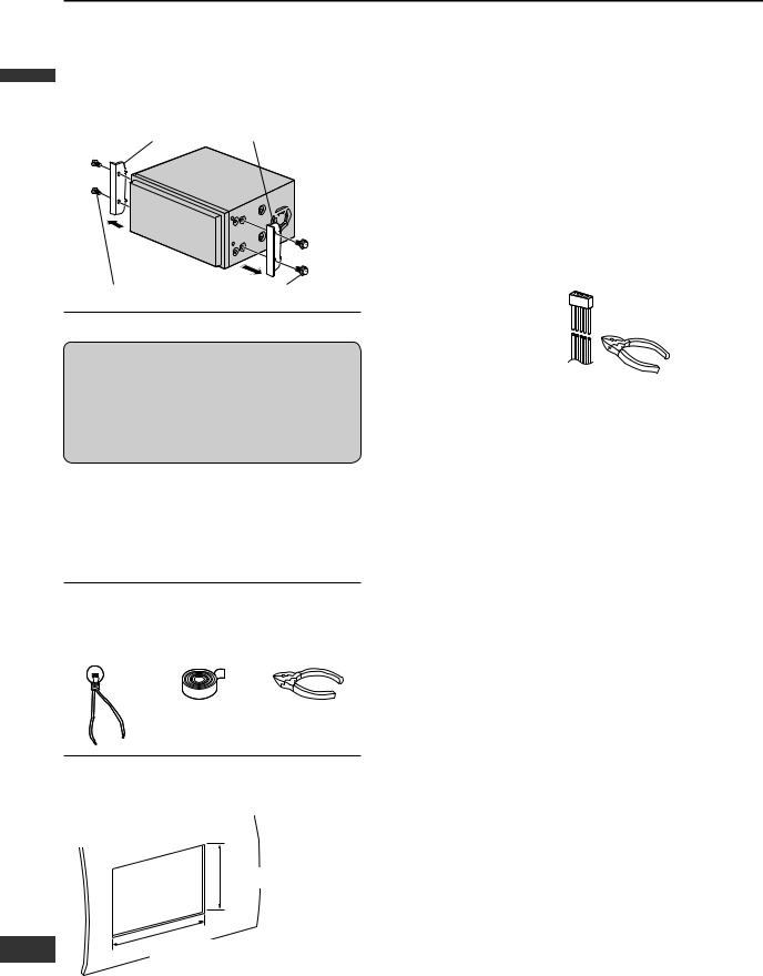
Transportation bracket removal
Be sure to remove the transportation brackets before use (installation). Use round head screws (5 mm 6 mm) for installation. ( page 7)
Be careful not to lose these screws. Transportation Bracket
Round head screw (5 mm 6 mm)
Before installation
 Warning
This product is designed for operation with a negative grounded 12 V DC battery system. Never operate this product with other battery systems, especially
a 24 V DC battery system. If it is used in the wrong type of car, it may cause a fire or an accident.
Do not press the panel forcefully.
Do not scratch the panel with fingernails or any hard objects.
Do not bump the front panel.
Failure to observe the above may damage or break the glass on the surface of the touch panel.
Required tools
You’ll need a screwdriver and the following:
12 V DC |
Electrical |
Side-Cut |
Test Bulb |
Tape |
Pliers |
Dashboard specifications
Thickness
MIN. 4.75 mm {3/16 }


 MAX. 5.56 mm {7/32 }
112 mm {4 3/8 }
182 mm {7 3/16 }
Identify all leads
The first step in installation is to identify all the car wires you will use when hooking up this unit.
As you identify each wire, we suggest that you label it using masking tape and a permanent marker. This will help avoid confusion when making connections later.
Note:
Do not connect the power connector to this unit until you have made all connections. If there are no plastic caps on the hooking wires, insulate all exposed leads with electrical tape until you are ready to use them.
Identify the leads in the following order.
Power lead
If your car has a radio or is pre-wired for one:
Cut the connector wires one at a time from the plug (leaving the leads as long as possible) so that you can work with individual leads. Turn the ignition on to the accessory position, and ground one lead of the test bulb to the chassis.
Touch the other lead of the test bulb to each of the exposed wires from the cut radio connector plug. Touch one wire at a time until you find the outlet that causes the test bulb to light.
Now turn the ignition off and then on. If the bulb also turns off and on, that outlet is the car power lead.
If your car is not wired for an audio unit:
Go to the fuse block and find the fuse port for radio (RADIO) accessory (ACC) or ignition (IGN).
Battery lead
If this unit has a yellow lead, you will need to locate the car’s battery lead. Otherwise you may ignore this
procedure. (The yellow battery lead provides continuous power to maintain a clock or other functions.)
If your car has a radio or is pre-wired for one: With the ignition and headlights off, identify the car
battery lead by grounding one lead of the test bulb to the chassis and checking the remaining exposed wires from the cut radio connector plug.
If your car is not wired for an audio unit:
Go to the fuse block and find the fuse port for the battery, usually marked BAT.
Speakers (not supplied)
Identify the car speaker leads. There are two leads for each speaker, usually color coded.
A handy way to identify the speaker leads and the speaker they are connected to is to test the leads using a 1.5 V AA battery as follows.
Hold one lead against one pole of the battery and stroke the other lead across the other pole. You will hear a
4
scraping sound in a speaker if you are holding a speaker lead.
If not, keep testing different lead combinations until you have located all the speaker leads. When you label them, include the speaker location for each.
Connect all leads
Now that you have identified all the wires in the car, you’re ready to begin connecting them to this unit wires. Electrical Connections ( page 10 – 11) shows the proper connections and color coding of the leads.
We strongly recommend that you test the unit before making a final installation.
You can set the unit on the floor and make temporary connections to test the unit. Use electrical tape to cover all exposed wires.
Important:
Connect the red power lead last, after you have made and insulated all other connections.
Ground
Connect the black ground lead of the power connector to the metal car chassis.
Speakers
Connect the speaker wires. See the wiring diagram for the proper hookups. Follow the diagram carefully to avoid damaging the speakers and this unit.
The speakers used must be able to handle more than 50 W of audio power. If using optional audio power, the speakers should be able to handle the maximum amplifier output power. Speakers with low input ratings can be damaged.
Speaker impedance should measure 4 – 8 , which is typically marked on most speakers. Lower or higher impedance speakers will affect output and can cause both speaker and this unit damage.
Battery
Connect the yellow battery lead to the correct radio wire or to the battery fuse port on the fuse block.
Equipment
Connect any optional equipment according to the instructions furnished with the equipment. Read the operating and installation instructions of any equipment you will connect to this unit.
Power
Connect the red power lead to the correct car radio wire or to the appropriate fuse port on the fuse block.
If this unit functions properly with all these connections made, disconnect the wires and proceed to the final installation.
Final installation
Lead connections
Connect all wires, making sure that each connection is insulated and secure. Bundle all loose wires and fasten them with tape so they will not fall down later. Now insert this unit into the mounting collar.
Congratulations! After making a few final checks, the new unit is ready for use.
Final checks
1.Make sure that all wires are properly connected and insulated.
2.Make sure that this unit is securely held in the mounting collar.
3.Turn on the ignition to check the unit for proper operation.
If you have difficulties, consult your nearest authorized professional installer for assistance.
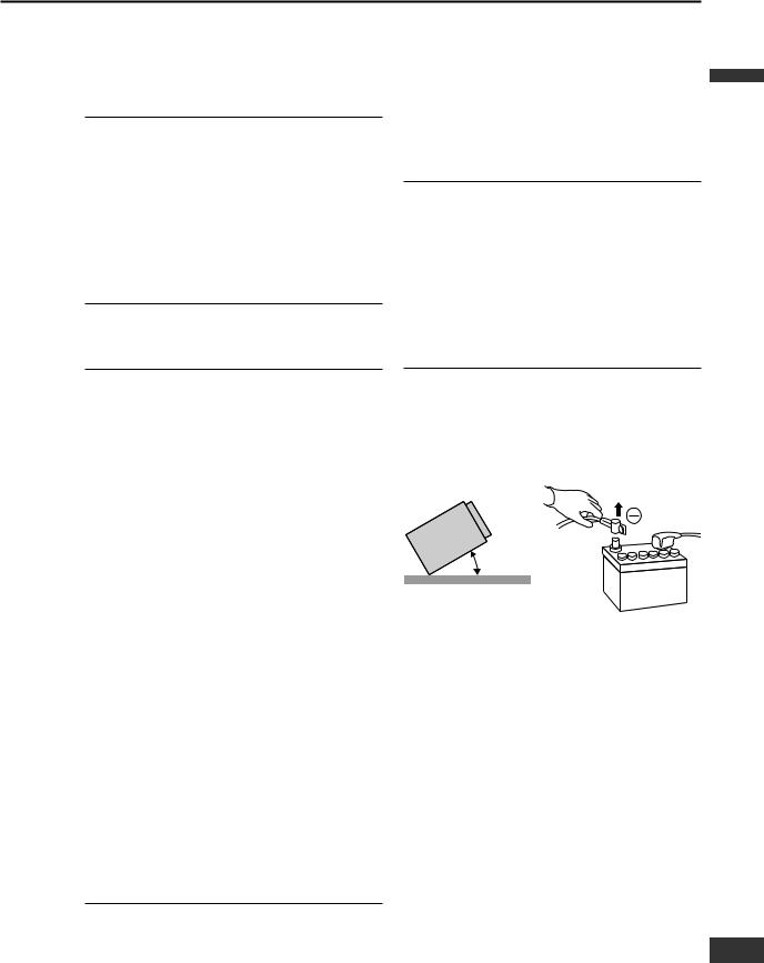
Precautions
Disconnect the cable from the negative (–) battery terminal.
Unit should be installed in a horizontal position with the front end up at a convenient angle, but less than 30°.
0 – 30°
This unit should be professionally installed. In case of difficulty, please consult with your nearest professional installer.
1.This unit only operates in a 12 V DC negative ground system.
2.Follow the electrical connections carefully
( page 10 – 11). Failure to do so may result in damage to the unit.
3.Connect the power lead after all other connections are made.
4.Be sure to connect the battery lead (yellow) to the positive terminal (+) of the battery or fuse block (BAT) terminal.
5.Insulate all exposed wires to prevent short circuiting.
6.Secure all loose wires after installing the unit.
7.Please carefully read the operating and installation instructions of the respective equipment before connecting it to this unit.
English
5
5
Loading...