


OE217-00 & OE217-01 |
Digital Room Sensors |
Description |
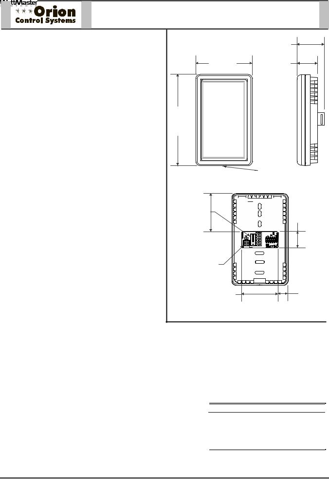
The OE217 series of Touch Screen Digital Room Sensors are used to sense Space Temperature only or Space Temperature & Space Humidity. The OE217-00 model is the Space Temperature Sensor only model and can be used with the VCM-X Controller (OE332-23-VCMX) and the VAV/Zone Controller (OE324-02). The OE217-01 is a combination Space Temperature & Space Humidity Sensor model and can only be used with the VCM-X Controller.
Besides sensing Temperature & Humidity, the Digital
Room Sensors also provide these other useful features:
• User Friendly Graphical LCD Display with LED Backlight
• Display the Current Space and Outdoor Air
Temperature
• Display the Current Space Humidity and Outdoor
Air Relative Humidity (OE217-01 Model Only)
• Display the current Zone Setpoint Temperature
• Equipped With Push Buttons for Changing the Zone Setpoint Temperature
• Equipped With an Override Button for Forcing the VAV/Zone Controller or VCM-X Controller into Occupied Operation from Unoccupied Operation
• Provides graphics to indicate the mode of operation
• Provides LEDs to indicate Schedule Override, Button Push, and Alarms
Both sensors connect to the controllers using TSDRSC modular cables of multiple lengths connected between the controller and the sensor. The TSDRSC modular cables should not run in conduit with other AC line voltage wiring or with any conductors carrying highly inductive loads.
Mounting
The Digital Room Sensor is designed to be mounted to a vertical, 2” x 4” electrical box recessed in the wall. If the wall cannot be penetrated, a plastic surface mount box such as those made by WiremoldTM, may be used to mount the sensor to the wall surface. The Sensor is mounted by removing the front cover and fastening the housing base to the electrical box using the supplied (2) 6/32” x 1” machine screws. The Modular cable is then plugged into the phone jack located on the circuit board that is mounted on the cover. The cover is then placed onto the housing base and the Allen Screw on the bottom of the base is adjusted to hold the cover in place.
|
|
Technical Data |
|
|
|
OE217-00 & OE217-01 Digital Room Sensor |
|
|
||
|
|
|
|
|
|
|
||||
|
|
|
|
|
|
|
|
|
|
|
|
|
Sensor Element |
Type III Thermistor 10k ohm |
|
Display |
|
|
112 x 64 Monochrome Graphical LCD |
|
|
|
|
|
@ 77 F Digital Sensing Device |
|
|
|
|
w/LED Backlight |
|
|
|
|
Sensor Reading |
40 F to 120 F |
Connection |
|
|
RJ-45 Modular Female Jack |
|
||
|
|
Range |
RH = 0-100% |
|
|
|
|
3.2 oz. |
|
|
|
|
Ambient |
-40 F to 180 F |
|
Weight |
|
|
|
||
|
|
Temperature |
|
|
|
|
|
|
|
|
|
|
Limits |
|
|
|
|
|
|
|
|
|
|
Accuracy |
RH +/-2%, Temp +/- .5 F |
|
|
|
|
|
|
|
|
|
|
|
|
|
|
||||
|
|
Three Year Warranty |
|
|
WattMaster reserves the right to change specifications without notice |
|
|
|||
|
|
|
|
|
|
|
|
|
|
|
|
|
|
|
|
|
|
|
|
|
|
Form: ORION-OE217-01-DigitalRoomSensor-1C.doc |
|
|
|
|
Page 1 of 1 |
|||||

TSDRSC-XX |
Digital Sensor Cable |
Description
The TSDRSC Cables are used to connect power and communications between the WattMaster Digital Room Sensor or Digital CO2 Sensor and the VCM-X Controller or VAV/Zone Controller.
The TSDRSC Cables are prefabricated plenum-rated cables with RJ45 Connectors on both ends of the cable for connection between the Digital Room Sensor, Digital CO2 Sensor, and the VCM-X or VAV/Zone Controller.
The TSDRSC Cables are labeled near each end with the cable part number.
The TSDRSC Cables are available in 5, 10, 15, 25, 40, 80, 120 & 160 feet lengths. These lengths should
satisfy most job requirements. For length requirements other than those listed, the MS000029 Modular Room Sensor Cable Coupler can be used to connect two of the TSDRSC Cables together to provide for your specific-length requirements.
The plug-in design of the TSDRSC Cables eliminates costly wiring errors and makes system installation easy. The cable components are all UL approved.
Technical Data |
TSDRSC Digital Sensor Cables |
|
TSDRSC Cable Available |
TSDRSC-5 (5 Ft.) |
|
Lengths and Part Numbers |
TSDRSC-10 (10 Ft.) |
|
|
TSDRSC-15 (15 Ft.) |
|
|
TSDRSC-25 (25 Ft.) |
|
|
TSDRSC-40 (40 |
Ft.) |
|
TSDRSC-80 (80 |
Ft.) |
|
TSDRSC-120 (120 |
Ft.) |
|
TSDRSC-160 (160 |
Ft.) |
Cable Type |
Plenum-rated |
|
|
|
|
Wire Size |
24 AWG Stranded |
|
|
8 Conductor |
|
Terminations |
(2) RJ-45 |
|
|
Connectors |
|
|
|
|
Three Year Warranty |
|
|
Current Rating of |
24 AWG Wire = 0.577 Amps |
Cable Wire |
(Maximum Amps |
|
For Power Transmission) |
Wire Colors |
Brown, Blue, White W/ Blue Stripe, White |
|
W/ Brown Stripe, Orange, |
|
White W/ Orange Stripe, Green, |
|
White W/ Green Stripe |
UL Listing No. |
CMP-UL As Per UL 910 |
|
Gray |
Cable Sheath |
|
Color |
|
WattMaster reserves the right to change specifications without notice
Form: ORION-ModularCable-TSDRSC-1A.doc |
Page 1 of 1 |

OE217-02 & OE217-03 |
E-BUS Digital Room Sensors |
Description |
The OE217 series of Touch Screen E-BUS Digital Room |
|
|
|
|
|
|
|
|
|
|
1.00 |
||||
Sensors are used to sense Space Temperature only or |
|
|
|
|
|
|
|
|
|
|
|
|
|
|
|
Space Temperature & Space Humidity. The OE217-02 |
|
|
|
|
|
|
2.80 |
|
|
|
|
|
0.69 |
||
|
|
|
|
|
|
|
|
|
|
|
|||||
model is the Space Temperature Sensor only model and |
|
|
|
|
|
||||||||||
|
|
|
|
|
|
|
|
||||||||
|
|
|
|
|
|
|
|
|
|
|
|
|
|
|
|
can be used with the VCB-X Controller (OE335-23-VCBX) |
|
|
|
|
|
|
|
|
|
|
|
|
|
|
|
and the VAV/Zone Controller (OE3XX-0X). The OE217-03 |
|
|
|
|
|
|
|
|
|
|
|
|
|
|
|
|
|
|
|
|
|
|
|
|
|
|
|
|
|
|
|
|
|
|
|
|
|
|
|
|
|
|
|
|
|
|
|
is a combination Space Temperature & Space Humidity |
|
|
|
|
|
|
|
|
|
|
|
|
|
|
|
Sensor model and can only be used with the VCB-X |
|
|
|
|
|
|
|
|
|
|
|
|
|
|
|
Controller. |
|
|
|
|
|
|
|
|
|
|
|
|
|
|
|
Besides sensing Temperature & Humidity, the E-BUS |
|
|
|
|
|
|
OVERRIDE |
ALARM |
|||||||
Digital Room Sensors also provide these other useful |
4.55” |
|
|
|
|
|
|||||||||
|
|
|
|
|
|
|
|
|
|
|
|
|
|
|
|
features: |
|
|
|
|
|
|
Display |
Override |
|||||||
|
|
|
|
|
|
|
|||||||||
•User Friendly Graphical LCD Display with LED Backlight
•Display the Current Space and Outdoor Air
Temperature |
Cover Set |
Side View |
Front View |
Screw |
•Display the Current Space Humidity and Outdoor Air Relative Humidity (OE217-03 Model Only)
•Display the current Zone Setpoint Temperature
|
E-BUS Cable |
0.81 |
• Equipped With Push Buttons for Changing the |
Connection |
|
MICROCHIP PIC24HJ 256GP206 |
||
Zone Setpoint Temperature |
|
|
|
1.87 |
SHLD |
• Equipped With an Override Button for Forcing the |
-COM |
|
|
+12Vdc |
|
|
|
GND |
VAV/Zone Controller or VCB-X Controller into |
|
|
Occupied Operation from Unoccupied Operation |
Remote Thermistor |
|
|
Sensor Connector |
|
•Provides graphics to indicate the mode of operation
•Provides LEDs to indicate Schedule Override,
Button Push, and Alarms |
1.81 |
|
|
|
|
0.49 |
Both sensors connect to the controllers using E-BUS |
|
|
Back View |
|||
cables of multiple lengths connected between the |
|
|
||||
|
|
|
|
|
|
|
controller and the sensor. The E-BUS cables should not |
|
|
|
|
|
|
run in conduit with other AC line voltage wiring or with any |
|
|
|
|
|
|
conductors carrying highly inductive loads. |
|
|
|
|
|
|
Mounting
The Digital Room Sensor is designed to be mounted to a vertical, 2” x 4” electrical box recessed in the wall. If the wall cannot be penetrated, a plastic surface mount box such as those made by WiremoldTM, may be used to mount the sensor to the wall surface. The Sensor is mounted by removing the front cover and fastening the housing base to the electrical box using the supplied (2) 6/32” x 1” machine screws. The E-BUS cable is then plugged into the E-BUS connector located on the circuit board that is mounted on the cover. The cover is then placed onto the housing base and the Allen Screw on the bottom of the base is adjusted to hold the cover in place.
|
|
Technical Data |
|
|
OE217-02 & OE217-03 E-BUS Digital Room Sensor |
|
|
|
||
|
|
|
|
|
|
|
||||
|
|
|
|
|
|
|
112 x 64 Monochrome Graphical LCD |
|
|
|
|
|
Sensor Element |
Type III Thermistor 10k ohm |
|
Display |
|
|
|
||
|
|
|
@ 77 F Digital Sensing Device |
|
|
|
w/LED Backlight |
|
|
|
|
|
Sensor Reading |
40 F to 120 F |
Connection |
|
E-BUS |
|
|
||
|
|
Range |
RH = 0-100% |
|
|
|
3.2 oz. |
|
|
|
|
|
Ambient |
-40 F to 180 F |
|
Weight |
|
|
|
||
|
|
Temperature |
|
|
|
|
|
|
|
|
|
|
Limits |
|
|
|
|
|
|
|
|
|
|
Accuracy |
RH +/-2%, Temp +/- .5 F |
|
|
|
|
|
|
|
|
|
|
|
|
|
|
|
|||
|
|
Three Year Warranty |
|
|
WattMaster reserves the right to change specifications without notice |
|
|
|
||
|
|
|
|
|
|
|
|
|
|
|
|
|
|
|
|
|
|
|
|
|
|
Form: ORION-OE217-02-03-EBUS-DRS-1A.doc |
Page 1 of 1 |
OE217-04 |
E-BUS Digital Room Sensor |
Description
The OE217-04 E-BUS Digital Room Space & Humidity Sensor is used to sense Space Temperature & Space Humidity. The E-BUS Digital Room Sensor can be used with the VCB-X Controller (Orion Part No. OE335-23-VCB-X; AAON Part No. V04740).
The E-BUS Digital Room Sensor connects to the controller using E-BUS cables of multiple lengths connected between the controller and the sensor. The E-BUS cables should not run in conduit with other AC line voltage wiring or with any conductors carrying highly inductive loads.
Mounting
The E-BUS Digital Room Sensor is designed to be mounted to a vertical, 2” x 4” electrical box recessed in the wall. If the wall cannot be penetrated, a plastic surface mount box such as those made by WiremoldTM, may be used to mount the sensor to the wall surface. The Sensor is mounted by removing the front cover and fastening the housing base to the electrical box using the supplied (2) 6/32” x 1” machine screws. The E-BUS cable is then plugged into the E- BUS connector located on the circuit board that is mounted on the cover. The cover is then placed onto the housing base and the Allen Screw on the bottom of the base is adjusted to hold the cover in place.
|
|
|
1.00 |
2.80 |
|
|
0.69 |
4.55” |
|
|
|
|
|
Cover Set |
|
Front View |
|
Screw |
Side View |
E-BUS Cable |
|
|
0.81 |
Connection |
|
MICROCHIP |
|
256GP206 |
PIC24HJ |
||
1.87 |
|
SHLD |
|
|
-COM |
|
|
|
GND |
|
|
|
+12Vdc |
|
|
|
|
|
|
Remote Thermistor |
|
|
|
Sensor Connector |
|
|
|
1.81 |
|
|
0.49 |
Back View |
|
||
Technical Data |
|
|
OE217-04 E-BUS Digital Room Sensor |
||
|
|
||||
|
|
|
|
|
|
Sensor Element |
Digital Sensing Device |
Accuracy |
|
|
RH +/-2%, Temp +/- .5 F |
Sensor Reading |
40 F to 120 F |
Connection |
|
|
E-BUS |
Range |
RH = 0-100% |
|
|
|
3.2 oz. |
Ambient |
-40 F to 180 F |
Weight |
|
|
|
Temperature |
|
|
|
|
|
Limits |
|
|
|
|
|
|
|
|
|
||
Three Year Warranty |
|
WattMaster reserves the right to change specifications without notice |
|||
|
|
|
|
|
|
Form: ORION-OE217-04-EBUS-DRS-1A.doc |
Page 1 of 1 |

BK000081 – Sensor Mounting Plate 
Description
The BK00081 Sensor Mounting Plate is used, if necessary, to cover the Sensor sheet rock opening. It is provided with the following Sensors:
•OE217-00 - Digital Room Temperature Sensor
•OE217-01 - Digital Room Temperature and Humidity Sensor
•OE217-02 - E-BUS Digital Room Temperature Sensor
•OE217-03 - E-BUS Digital Room Temperature and Humidity Sensor
•OE217-04 - E-BUS Digital Room Temperature Sensor (No LCD Display)
•OE256-01 - Wall Mounted CO2 Sensor
•OE256-05 - E-BUS Wall Mounted CO2 Sensor
Mounting
The Mounting Plate screws onto the back of the Sensor’s housing base. The mounting plate is then mounted and covers the recessed space in the wall. A locking screw secures the Sensor to the wall.
Form: ORION-BK000081-Sensor-Mounting-Plate-1A.doc |
Page 1 of 1 |

MS000248 - E-BUS Adapter Hub
Description
The MS000248 E-BUS Adapter Hub is used to provide a connection point for multiple E- BUS Sensors or Modules. This E- BUS Adapter Hub has four
ports. One port is used to connect the Hub to an E-BUS Expansion Port on the VCB-X Controller or a VCB-X Expansion Module using EBC E-BUS cables. This leaves three ports available for E-BUS Sensors and other Modules.
The EBC Cables are plenum-rated high flex wire cables with an EBC Connector on each end of the cable for connection between the Sensors, Modules, and the VCB-X Controller.
|
|
|
|
|
|
|
|
ADAPTER HUB |
|||||||||||||
|
|
|
|
|
|
|
|
|
RIGHT END |
||||||||||||
|
|
|
|
|
|
|
|
|
|
|
|
|
VIEW |
||||||||
|
|
|
|
|
|
|
|
|
|
|
|
|
|
|
|
|
|
|
|
|
|
|
|
|
|
|
|
|
|
|
|
|
|
|
|
|
|
|
|
|
|
|
|
|
|
|
|
|
|
|
|
|
|
|
|
|
|
|
|
|
|
|
|
|
|
|
|
|
|
|
|
0.762 |
|
|
|
|
|
|
|
|
|
|
|
|
|||
|
|
-AMP |
|
|
|
|
|
|
|
|
|
|
|
|
|
|
|
|
|||
1234 |
|
|
|
|
|
|
|
|
|
|
|
|
|
|
|
|
|
|
|
||
|
|
|
|
|
|
|
|
|
|
|
|
|
|
|
|
|
|
||||
|
|
|
|
|
|
|
|
|
|
|
|
|
|
|
|
|
|
|
|
|
|
|
|
|
|
|
|
|
|
ADAPTER HUB |
|||||||||||||
|
|
0.405 |
|
|
|
|
|
||||||||||||||
|
|
|
|
|
|
|
|||||||||||||||
ADAPTER HUB |
|
|
|
|
TOP VIEW |
||||||||||||||||
|
|
|
|
|
|
|
|
|
|
|
|
|
|
|
|
||||||
|
SIDE VIEW |
|
|
|
|
|
|
|
|
|
|
|
|
|
|
|
|
||||
|
|
|
|
|
|
|
|
|
|
|
|
|
|
|
|
|
|
|
|
|
|
|
|
|
|
|
|
|
|
|
|
|
|
|
|
|
|
|
|
|
|
|
|
|
|
|
|
|
|
|
|
|
|
|
|
|
|
|
|
|
|
|
|
|
|
|
|
|
|
|
|
|
|
|
|
|
|
|
|||||||||
|
|
|
|
|
|
|
|
|
0.327 |
|
|
|
|
||||||||
|
|
|
|
|
|
|
|
|
|
|
|
|
|
|
|
|
|||||
|
|
|
|
|
|
|
|
ADAPTER HUB |
|||||||||||||
|
|
|
|
|
|
|
|
|
|
LEFT END |
|||||||||||
|
|
|
|
|
|
|
|
|
|
|
|
|
VIEW |
||||||||
MS000248 E-BUS ADAPTER HUB
Technical Data |
|
MS000248 E-BUS Adapter Hub |
|
||
|
|
|
Terminations |
Hub - (4) EBC Connectors |
|
.
Three Year Warranty
WattMaster reserves the right to change specifications without notice
Form: AAON-MS000248-E-BUS-Adapter-1A.doc |
Page 1 of 1 |

HZ-EBC-248 - E-BUS Adapter Hub |
with 1.5 Ft. EBC Cable |
Description
The HZ-EBC-248 (AAON Part No. V17180) is comprised of the MS000248 E-BUS Adapter Hub and a 1.5 Foot EBC Cable (Part No. EBC-1.5F).
The E-BUS Adapter Hub is used to provide a connection point for multiple E-BUS Sensors or Modules. This E-BUS Adapter Hub has four ports. One port is used to connect the Hub to an E-BUS Expansion Port on the VCB-X Controller or a VCB-X Expansion Module using the supplied EBC- 1.5F cable. This leaves three ports available for E-BUS Sensors and other Modules.
The EBC Cable is a plenum-rated high flex cable with EBC Connectors on each end of the cable for connection between the Sensors, Modules, and the VCB-X Controller.
|
|
|
|
|
|
|
|
|
|
|
|
|
|
|
|
|
|
|
|
|
|
|
|
|
|
|
|
|
|
|
|
|
|
|
|
|
|
|
|
|
|
|
|
|
|
|
|
|
|
|
|
|
|
|
|
|
|
|
|
|
|
|
|
|
|
|
|
|
|
|
|
|
|
|
|
|
|
|
|
|
|
|
|
|
|
|
|
|
|
|
|
|
|
|
|
|
|
|
|
|
|
|
|
|
|
|
|
|
|
|
|
|
|
|
|
|
|
|
|
|
|
|
|
|
|
|
|
|
|
|
|
|
|
|
|
|
|
|
|
|
|
|
|
|
|
|
|
|
|
|
|
|
|
|
|
|
|
|
|
|
|
|
|
|
|
|
|
|
|
|
|
|
|
|
|
|
|
|
|
|
|
|
|
|
|
|
|
|
|
|
|
|
|
|
|
|
|
|
|
|
|
|
|
|
|
|
|
|
|
|
|
|
|
|
|
|
|
|
|
|
|
|
|
|
|
|
|
|
|
|
|
|
|
|
|
|
|
|
|
|
|
|
|
|
|
|
|
|
|
|
|
|
|
|
|
|
|
|
|
|
|
|
|
|
|
|
|
|
|
|
|
|
|
|
|
|
|
|
|
|
|
|
|
|
|
|
|
|
|
|
|
|
|
|
|
|
|
|
|
|
|
|
|
|
|
|
|
|
|
|
|
|
|
|
|
|
|
|
|
|
|
|
|
|
|
|
|
|
|
|
|
|
|
|
|
|
|
|
|
|
|
|
|
|
|
|
|
|
|
|
|
|
|
|
|
|
|
|
|
|
|
|
|
|
|
|
|
|
|
|
|
|
|
|
|
|
|
|
|
|
|
|
|
|
|
|
|
|
|
|
|
|
|
|
|
|
|
|
|
|
|
|
|
|
|
|
|
|
|
|
|
|
|
|
|
|
|
|
|
|
|
|
|
|
|
|
|
|
|
|
|
|
|
|
|
|
|
|
|
|
|
|
|
Technical Data |
HZ-EBC-248 E-BUS Adapter Hub with 1.5 Ft. EBC Cable |
|
|||||||||||||||||||||||||||||
|
|
|
|
|
|
|
|
|
|
|
|
|
|
|
|
|
|
|
|
|
|
|
|
||||||||||
|
|
EBC E-BUS Cable |
EBC-1.5F (1.5 Foot) |
Current Rating of |
|
300 Vrms Min = 10.15 Ohms per 1000 |
|
||||||||||||||||||||||||||
|
|
Available Length and |
|
Cable Wire |
|
feet @ 20 Deg Celsius, Nominal |
|
||||||||||||||||||||||||||
|
|
Part Number |
|
|
|
|
|
|
|
|
|
|
|
|
|
|
|
|
|
|
|
|
|
|
|
|
|
|
|
|
|
|
|
|
|
Cable Type |
Plenum-rated High Flex Wire |
Wire Colors |
|
Red/Black First Pair; White/Blue Second |
|
||||||||||||||||||||||||||
|
|
|
|
|
|
|
|
|
|
|
|
|
|
|
|
|
|
|
|
|
|
|
|
|
|
|
|
|
|
|
|
Pair |
|
|
|
Wire Size |
19 Strands of 32 Gage Wire, 4 |
UL Listing No. |
|
|
|
|
|
|
|
|
|
|
|
|
|
|
CMP/CL3P/FPLP |
|
|||||||||||||
|
|
|
Conductor |
|
|
|
|
|
|
|
|
|
|
|
|
|
|
|
|
|
|
|
|
|
|
|
|
|
|
|
|
|
|
|
|
Terminations |
Hub - (4) EBC Connectors |
Cable Sheath |
|
White, Plenum Rated CL3P/CMP |
|
||||||||||||||||||||||||||
|
|
|
Cable – 2 EBC Connectors |
Color |
|
with “WATTMASTER EBUS” |
|
||||||||||||||||||||||||||
|
|
|
|
|
|
|
|
|
|
|
|
|
|
|
|
|
|
marking every foot. |
|
||||||||||||||
|
|
|
|
|
|
|
|
|
|
|
|
|
|
|
|
|
|
|
|
|
|
|
|||||||||||
|
|
Three Year Warranty |
|
WattMaster reserves the right to change specifications without notice |
|
||||||||||||||||||||||||||||
|
|
|
|
|
|
|
|
|
|
|
|
|
|
|
|
|
|
|
|
|
|
|
|
|
|
|
|
|
|
|
|
|
|
|
|
|
|
|
|
|
|
|
|
|
|
|
|
|
|
|
|
|
|
|
|
|
|
|
|
|
|
|
|
|
|
|
|
|
|
Form: AAON-HZ-EBC-248-E-BUS-Adapter-1A.doc |
|
|
|
|
|
|
|
|
|
|
|
|
|
|
|
|
|
|
|
|
|
|
|
|
|
Page 1 of 1 |
|||||

 OE365-15-EBA-A - E-BUS Adapter Board
Description |
|
|
|
|
|
|
|
|
|
|
|
|
|
|
|
|
|
|
|
|
|
|
|
|
|
|
|
|
|
|
|
|
|
|
|
|
|
|
|
The OE365-15-EBA-A E-BUS |
|
|
|
|
|
|
|
|
|
|
|
|
|
|
|
|
|
|
|
|
|
|
|
|
|
|
|
|
|
|
|
|
|
|
|
|
|
|
|
Adapter Board is used to provide a |
|
|
|
|
|
|
|
|
|
|
|
|
|
|
|
|
|
|
4.12 |
|
|
|
|
|
|
|
|
|
|
|
1.33 |
|
|
||||||
|
|
|
|
|
|
|
|
|
|
|
|
|
|
|
|
|
|
|
|
|
|
|
|
|
|
|
|||||||||||||
|
|
|
|
|
|
|
|
|
|
|
|
|
|
|
|
|
|
|
|
|
|
|
|
|
|
|
|
|
|||||||||||
connection point for multiple E- |
|
|
|
|
|
|
|
|
|
|
|
|
|
|
|
|
|
|
|
|
|
|
|
|
|
|
|
|
|
|
|
|
|
|
|
|
|
|
|
BUS Sensors or Modules. |
|
|
|
|
|
|
|
|
|
|
|
|
|
|
|
|
|
|
|
|
|
|
|
|
|
|
|
|
|
|
|
|
|
|
|
|
|
|
|
|
|
|
|
|
|
|
|
|
|
|
|
|
|
|
|
|
|
|
|
|
|
|
|
|
|
|
|
|
|
|
|
|
|
|
|
|
|
|
|
The E-BUS Adapter Board is also |
|
|
|
|
|
|
|
|
|
|
|
|
MODULAR |
|
R+ |
|
|
|
|
|
|
|
|
|
|
|
|
|
|
|
|||||||||
|
|
|
|
|
|
|
|
|
|
|
|
|
|
|
|
|
|
|
|
|
|
|
|
|
|
|
|||||||||||||
used for connecting an EBTRON |
® |
|
|
|
|
|
|
|
|
|
|
|
|
|
EBUS |
|
MADE IN USA |
MSTP |
T- |
|
|
|
|
|
|
|
|
|
|
|
|
|
|
|
|||||
|
|
|
|
|
|
|
|
|
|
|
|
|
|
|
YS102478 |
SH |
|
|
|
|
|
|
|
|
|
|
|
|
|
|
|
||||||||
|
|
|
|
|
|
|
|
|
|
|
|
|
|
|
|
|
|
|
|
|
REV 0 |
|
|
|
|
|
|
|
|
|
|
|
|
|
|
|
|
|
|
GTC-116 Airflow Measurement |
|
|
|
|
|
|
|
|
|
|
|
|
|
|
|
|
|
|
|
|
|
|
EBUS |
|
|
|
3.00 |
|
|
|
|
|
|
|
|
|
|||
|
|
|
|
|
P1 |
P2 |
|
|
|
R+ |
|
|
|
|
|
|
|
|
|
|
|
||||||||||||||||||
|
|
|
|
|
J1 |
J2 J3 |
|
|
|
SH |
|
|
|
|
|
|
|
|
|
|
|
|
|
|
|
||||||||||||||
|
|
|
|
|
|
|
|
|
|
|
|
|
|
|
|
|
|
|
|
|
|
|
|
|
|
|
|
|
|
|
|
|
|
|
|
|
|||
Digital Transmitter or a Green- |
|
|
|
|
|
|
|
|
|
|
|
|
|
|
|
|
|
|
|
|
|
|
|
T- |
|
|
|
|
|
|
|
|
|
|
|
|
|
|
|
|
|
|
|
|
|
|
|
|
|
|
|
|
|
|
|
|
|
|
|
|
|
|
|
|
|
|
|
|
|
|
|
|
|
|
|
|
|
||
|
|
|
|
|
|
|
|
|
|
|
|
|
|
|
|
|
|
|
|
|
|
|
|
|
|
|
|
|
|
|
|
|
|
|
|
|
|
||
TrolTM GA-200-N Transmitter Mod- |
|
|
|
|
|
|
|
|
|
|
|
|
|
|
|
|
|
|
|
|
|
|
|
|
|
|
|
|
|
|
|
|
|
|
|
|
|
||
|
|
|
|
|
|
|
|
|
|
|
|
|
|
|
|
|
|
|
|
|
|
|
|
|
|
|
|
|
|
|
|
|
|
|
|
||||
ule with GF Series Airflow Monitor- |
|
|
|
|
|
|
|
|
|
|
|
|
|
|
|
|
|
|
|
|
|
|
|
|
|
|
|
|
|
|
|
|
|
|
|
|
|
||
|
|
|
|
|
|
|
|
|
|
|
|
|
|
|
|
|
|
|
|
|
|
|
|
|
|
|
|
|
|
|
|
|
|
|
|
||||
ing Station to the VCM-X |
|
|
|
|
|
|
|
|
|
|
|
|
|
|
|
|
|
|
|
|
|
|
|
|
|
|
|
|
|
|
|
|
|
|
|
|
|
|
|
|
|
|
|
|
|
|
|
|
|
|
|
|
|
|
|
|
|
|
|
|
|
|
|
|
|
|
|
|
|
|
|
|
|
|
|
|
|
|
|
E-BUS Modular Controller*, RNE |
|
|
|
|
|
|
|
|
|
|
|
|
|
|
|
|
|
|
|
|
|
|
|
|
|
|
|
|
|
|
|
|
|
|
|
||||
Controller*, or VCB-X Controller. |
|
|
|
|
|
|
|
|
|
|
|
|
|
|
|
|
|
|
|
|
|
|
|
|
|
|
|
|
|
|
|
|
|
|
|
|
|
|
|
You must wire the EBTRON® or |
|
|
|
|
|
|
|
|
|
|
|
|
|
|
|
|
|
|
|
|
|
|
|
|
|
|
|
|
|
|
|
|
|
|
|
|
|
|
|
GreenTrolTM Airflow Measurement |
|
|
|
|
|
|
|
|
|
|
|
|
|
|
|
|
|
|
|
|
|
|
|
|
|
|
|
|
|
|
|
|
|
|
|
||||
Digital Transmitter to this Adapter |
|
|
|
|
|
|
|
|
|
|
|
|
|
|
|
|
|
|
|
|
|
|
|
|
|
|
|
|
|
|
|
|
|
|
|
||||
Board. Up to (3) EBTRON® or |
|
|
|
|
|
|
|
|
|
|
|
|
|
|
|
|
|
|
|
|
|
|
|
|
|
|
|
|
|
|
|
|
|
|
|
|
|
|
|
GreenTrolTM Airflow Measurement |
|
|
|
|
|
|
|
|
|
|
|
|
|
|
|
|
|
|
|
|
|
|
|
|
|
|
|
|
|
|
|
|
|
|
|
||||
Digital Transmitters can be attached to the Adapter Board when using the VCM-X E-BUS Controller or RNE Controller and up to (4) EBTRON® or GreenTrolTM Airflow Measurement Digital Transmitters can be attached to the Adapter Board when using the VCB-X Controller.
The E-BUS Adapter Board has (3) HSSC Connections. One of these E-BUS ports is used to connect the Board to the E-BUS Port on the VCM-X E-BUS Controller or RNE Controller using an HSSC E- BUS cable.
The E-BUS Adapter Board also has (4) Modular E-BUS ports. One of these Modular E-BUS ports is used to connect the Board to the E-BUS Port on the VCB-X Controller.
The EBUS Adapter Board also has (2) MSTP E-BUS Connections. The AirFlow Monitoring Station(s) connect to one of the MSTP E-BUS Connections.
*NOTE: With custom VCM-X software, the Paragon MicroTrans EQ series Air Flow Monitoring Station can be used and would wire into the E-BUS Adapter Board the same way.
|
Technical Data |
|
|
OE365-15-EBA-A E-BUS Adapter Board |
|
|
|
|
|||
|
|
|
|
|
|
|
Terminations |
(4) EBC Connections |
|
. |
|
|
|
(2) MSTP E-BUS Connections |
|
|
|
|
|
(3) HSSC Connections |
|
|
|
|
|
|
|
|
|
|
Three Year Warranty |
|
|
WattMaster reserves the right to change specifications without notice |
|
|
|
|
|
|
|
EBTRON® is a registered trademark of Ebtron, Inc., Loris, SC.
GreenTrolTM is a registered trademark of GreenTrol Automation, Inc. Loris, SC. Paragon® is a registered trademark of Paragon Controls, Inc. Santa Rosa, CA
Form: ORION-OE365-15-EBA-A-E-BUS-Adapter-Board-1C.doc |
Page 1 of 1 |

EBC-XXXF – EBC E-BUS Cables
Description
The EBC E-BUS Cables are used to connect power and communications between the VCB-X Controller, VCB-X Expansion Module, E-BUS Modules, and E-BUS Sensors.
The EBC E-BUS Cables are plenumrated high flex wire cables with an EBC Connector on each end of the cable.
The EBC E-BUS Cables are labeled with “WATTMASTER E-BUS” marking every foot.
The EBC E-BUS Cables are available in 1, 1.5, 3, 10, 15, 25, 50, 75, 100, 150, and 250 foot lengths and additionally a 1000 foot long spool. These lengths should satisfy most job requirements. For length requirements other than those listed, the MS000248 E-BUS Adapter Hub can be used to connect EBC E-BUS Cables together to provide for your specific-length requirements.
The plug-in design of the EBC E-BUS Cables eliminates costly wiring errors and makes system installation easy.
The cable components are all UL approved.
1 |
3M |
4 |
32 |
FXX
-EBC
EBUS""WATTMASTER
Length
in Feet
EBUS""WATTMASTER
FXX
-EBC
1 |
2 |
43 |
|
3M |
|
CABLE SIDE
VIEW
EBC-XXF
E-BUS CABLE
|
Technical Data |
EBC-XXXF EBC E-BUS Cables |
|
|
|
EBC E-BUS Cable |
EBC-1-F (1 Foot) |
|
Available Lengths and |
EBC-1.5-F (1.5 Foot) |
|
Part Numbers |
EBC-3-F (3 Foot) |
|
|
EBC-25-F (25 Foot) |
|
|
EBC-50-F (50 Foot) |
|
|
EBC-75-F (75 |
Foot) |
|
EBC-100-F (100 |
Foot) |
|
EBC-150-F (150 |
Foot) |
|
EBC-250-F (250 |
Foot) |
|
EBC-SPOOL-F (1000 Foot |
|
|
Spool) |
|
Cable Type |
Plenum-rated High Flex Wire |
|
|
|
|
Wire Size |
19 Strands of 32 Gage Wire, 4 |
|
|
Conductor |
|
Terminations |
Cable – 2 EBC Connectors |
|
|
|
|
Current Rating of |
300 Vrms Min = 10.15 Ohms per 1000 |
Cable Wire |
feet @ 20 Deg Celsius, Nominal |
Wire Colors |
Red/Black First Pair; White/Blue Second |
|
Pair |
UL Listing No. |
CMP/CL3P/FPLP |
|
White, Plenum Rated CL3P/CMP |
Cable Sheath |
|
Color |
with “WATTMASTER EBUS” |
|
marking every foot. |
|
|
|
|
|
|
Three Year Warranty |
WattMaster reserves the right to change specifications without notice |
|
|
|
|
|
|
|
Form: ORION-EBC-XXXF-E-BUS-Cable-1B.doc |
Page 1 of 1 |
OE210-02, 211-02, 212-02, 213-02 |
Modular Room Sensors |
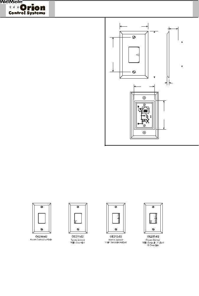
Description
The patented design, OE21x-02 series Modular Room Sensor provides accurate sensing of the room temperature. Its design allows for flush wall mounting yet rejects the influence of surface and internal wall temperatures. The Modular Room Sensor is used in conjunction with the Orion VAV/Zone Controller. Connection between the VAV/Zone Controller board and the Modular Room Sensor is by means of an RJ-45 Modular Cable. The Modular Room Sensor cannot be used for connection to the VCM- X controller. For these applications the Standard Room Sensor must be used. Please see the Orion Standard Room Sensor submittal sheet for information.
Sensors provided with the setpoint adjustment option can be programmed to allow a temperature range adjustment of ± 6° F from their standard setpoint. Sensors provided with the pushbutton override option can be programmed to provide a timed override duration of up to 8.0 hours.
The Room Sensor’s attractive styling and off white casing color make it suitable for most building decors. If interior decoration requires, the Modular Room Sensor casing can also be painted or wall papered without affecting the sensor's performance. Modular Room Sensors are available in 4 different configurations:
OE210-02 - Sensor Plain
OE211-02 - Sensor with Override
OE212-02 - Sensor with Setpoint Adjustment
OE213-02 - Sensor with Setpoint Adjustment and Override
3.25“
2.75“
0.88“
W |
|
|
|
|
|
|
|
|
|
|
|
|
|
|
|
|
|
A |
|
|
|
|
|
|
|
|
R |
|
|
|
|
|
2.50" |
||
M |
|
4.50“ |
|
|||||
O |
|
|
||||||
E |
|
|
|
|
|
|
|
|
R |
|
|
|
|
|
|
|
|
C |
|
|
|
|
|
|
|
|
O |
|
|
|
|
|
|
|
|
L |
|
|
|
|
|
|
|
|
E |
|
|
|
|
|
|
|
|
R |
|
|
|
|
|
|
|
|
|
|
|
|
|
|
|
|
|
|
|
|
|
|
|
|
|
|
|
|
|
|
|
|
|
|
|
|
|
|
|
|
|
|
|
|
|
|
|
|
|
|
|
|
|
|
0.25“ |
2.00“ |
|
YS101858 |
|
REV 0 |
|
|
MODULAR SENSOR |
PJ1 |
2.75“ |
R2 |
|
THERM1 |
|
R1 |
Wall Cut-Out Dimensions
When Sensor Is To Be
Mounted Without
Handy Box (By Others)
Modular cable from the VAV/Zone Controller to the Modular Room Sensor should not be run in conduit with other AC line voltage wiring, or with any conductors carrying highly inductive loads.
Mounting
The Room Sensors are designed to be mounted on a vertical, 2” x 4” electrical box recessed in the wall. If the wall cannot be penetrated, a plastic surface mount box such as those made by Wiremold , may be used to mount the sensor to the wall surface.
|
|
Technical Data |
|
|
OE210-02, OE211-02, OE212-02, OE213-02 |
|
|
|
|
|
|
||
|
|
|
|
|
Modular Room Sensor |
|
|
|
|
|
|
|
|
|
|
Sensor Element |
Type III Thermistor |
Mounting |
Designed to be Flush Mounted to Wall |
|
|
|
|
10k ohm @ 77º F |
|
using Vertical 2” x 4” Handy Box (by others) |
|
|
|
Accuracy |
0.4º F between 40º F to 95º F |
Connection |
RJ-45 Modular Female Jack |
|
|
|
Range |
-30º F to 150º F |
Weight |
4 oz. |
|
|
|
|
|
|
|
|
|
|
3 Year Warranty |
|
WattMaster reserves the right to change specifications without notice |
|
|
|
|
|
|
|
|
|
|
|
|
|
|
|
|
Form: ORION-ModularRoomSensor-1F.doc |
Page 1 of 1 |
FMRSC-XX |
Modular Room Sensor Cable |
Description
Description
The FMRSC Cables are used to connect power and communications between the Modular Room Sensor and the Orion VAV/Zone Controller.
The FMRSC Cables are prefabricated plenum-rated cables with RJ45 Connectors on both ends of the cable for connection between the Modular Room Sensor and the Orion VAV/Zone Controller.
The FMRSC Cables are labeled near each end with the cable part number.
The FMRSC Cables are available in 5, 10, 25, 40 and 80 feet lengths. These lengths should satisfy most
job requirements. For length requirements outside of this range, the MS000029 Modular Room Sensor Cable Coupler can be used to connect two of the FMRSC Cables together to provide for your specificlength requirements. Not more than one coupler should be used on a run. Maximum run is 160 feet.
The plug-in design of the FMRSC Cables eliminates costly wiring errors and makes system installation easy. The cable components are UL approved.
Technical Data |
|
|
|
FMRSC Modular Sensor Cables |
|
|
|
|
|
24 AWG Wire = 0.577 Amps |
|
FMRSC Cable Available |
FMRSC-5 (5 Ft.) |
Current Rating of |
|
|
|
Lengths and Part Numbers |
FMRSC-10 (10 Ft.) |
Cable Wire |
|
(Maximum Amps |
|
|
FMRSC-25 (25 Ft.) |
|
|
For Power Transmission) |
|
|
FMRSC-40 (40 Ft.) |
|
|
|
|
|
FMRSC-80 (80 Ft.) |
|
|
|
|
Cable Type |
Plenum-rated |
Wire Colors |
|
White W/ Green Stripe, Green W/ White |
|
|
|
|
|
Stripe, White W/ Orange Stripe, Orange |
|
|
|
|
|
W/ White Stripe, White W/ Blue Stripe, |
|
|
|
|
|
Blue W/ White Stripe |
|
Wire Size |
24 AWG Stranded |
UL Listing No. |
|
CMP-UL As Per UL 910 |
|
|
6 Conductor |
|
|
|
|
Terminations |
(2) RJ-45 |
Cable Sheath |
|
Gray |
|
|
Connectors |
Color |
|
|
|
|
|
|
|
|
|
Three Year Warranty |
|
WattMaster reserves the right to change specifications without notice |
|
||
|
|
|
|
|
|
Form: ORION-ModularCable-FMRSC-1B.doc |
Page 1 of 1 |
OE210, 211, 212 & 213 |
Standard Room Sensors |
Description |
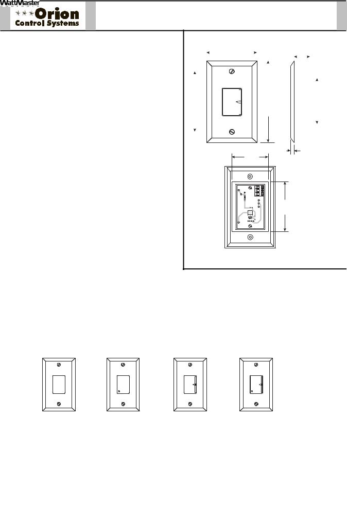
The patented design, OE21x series Standard Room Sen- |
|
|
|
|
|
2.75“ |
|
|
|
|
|
|
|
|
|
|
|
|
||
|
|
|
|
|
|
|
|
|
|
|
|
|
|
|
|
|
||||
sor provides accurate sensing of the room temperature. |
|
|
|
|
|
|
|
|
|
|
0.88“ |
|
|
|
|
|
|
|||
|
|
|
|
|
|
|
|
|
|
|
|
|
|
|
||||||
Its design allows for flush wall mounting yet rejects the |
|
|
|
|
|
|
|
|
|
|
|
|
|
|
|
|
|
|
|
|
influence of surface and internal wall temperatures. The |
|
|
|
|
|
|
|
|
|
|
|
|
|
|
|
|
|
|
|
|
|
|
|
|
|
|
|
|
|
|
|
|
|
|
|
|
|
|
|
||
|
|
|
|
|
|
|
|
|
|
|
|
|
|
|
|
|
|
|
||
Standard Room Sensor is used in conjunction with the |
|
|
|
|
|
|
|
|
|
|
|
|
|
|
|
|
|
|
|
|
|
|
|
|
|
|
|
|
|
|
|
|
|
|
|
|
|
|
|
||
Orion controllers. Wire terminals are provided on the sen- |
|
|
|
|
|
W |
|
|
|
|
|
|
|
|
|
|
|
|
|
|
sor for connection to the controllers. The Standard Room |
|
|
|
|
|
R |
|
|
|
|
|
|
|
|
|
|
|
|
|
|
|
|
|
|
|
|
|
A |
|
|
|
|
|
|
|
|
|
|
|
|
|
|
|
|
|
|
|
|
R |
|
|
|
|
|
|
|
|
|
|
2.50" |
||
|
|
3.25“ |
|
|
M |
|
|
|
|
|
|
|
|
|
|
|||||
|
|
|
|
E |
|
|
|
|
4.50“ |
|
|
|
|
|||||||
Sensor cannot be used for connection to the VAV/Zone |
|
|
O |
|
|
|
|
|
|
|
|
|||||||||
|
|
|
|
|
|
|
|
|
|
|||||||||||
controller. For this application the Modular Room Sensor |
|
|
|
|
|
C |
|
|
|
|
|
|
|
|
|
|
|
|
|
|
|
|
|
|
|
R |
|
|
|
|
|
|
|
|
|
|
|
|
|
||
|
|
|
|
|
|
|
O |
|
|
|
|
|
|
|
|
|
|
|
|
|
|
|
|
|
|
|
|
L |
|
|
|
|
|
|
|
|
|
|
|
|
|
|
|
|
|
|
|
|
E |
|
|
|
|
|
|
|
|
|
|
|
|
|
must be used. Please see the Orion Modular Room Sen- |
|
|
|
|
|
|
|
|
|
|
|
|
|
|
|
|
|
|
|
|
sor submittal sheet for information. |
|
|
|
|
|
|
|
|
|
|
|
|
|
|
|
|
|
|
|
|
|
|
|
|
|
|
|
|
|
|
|
|
|
|
|
|
|
|
|
||
|
|
|
|
|
|
|
|
|
|
|
|
|
|
|
|
|
|
|
|
|
Sensors provided with the setpoint adjustment option can |
|
|
|
be programmed to allow a temperature range adjustment |
0.25“ |
|
|
of ± 6°F from their standard setpoint. Sensors provided |
2.00“ |
|
|
with the pushbutton override option can be programmed |
|
|
|
to provide a timed override duration of up to 8.0 hours. |
|
|
|
The Room Sensor’s attractive styling and off white casing |
TMP |
|
|
AUX |
|
||
color make it suitable for most building decors. If interior |
GND |
|
|
OUT |
Wall Cut-Out Dimensions |
||
decoration requires, the Room Sensor casing can also be |
2.75“ |
Mounted Without |
|
|
|
|
When Sensor Is To Be |
painted or wall papered without affecting the sensor's per- |
|
Handy Box (By Others) |
|
formance. Room Sensors are available in 4 different con- |
|
|
|
figurations: |
|
|
|
|
OE210 Sensor Plain |
|
|
OE211 Sensor with Override |
|
|
|
OE212 Sensor with Setpoint Adjustment |
|
|
|
OE213 Sensor with Setpoint Adjustment and |
|
|
|
|
Override |
|
|
Mounting
The Room Sensors are designed to be mounted on a vertical, 2” x 4” electrical box recessed in the wall. If the wall cannot be penetrated, a plastic surface mount box such as those made by Wiremold , may be used to mount the sensor to the wall surface.
|
W |
|
W |
|
A |
|
A |
|
R |
|
R |
|
M |
|
M |
|
E |
|
E |
|
R |
|
R |
|
C |
|
C |
|
O |
|
O |
OVR |
O |
OVR |
O |
L |
L |
||
|
E |
|
E |
|
R |
|
R |
OE210 |
OE211 |
OE212 |
OE213 |
Room Sensor - Plain |
Room Sensor |
Room Sensor |
Room Sensor |
|
With Override |
With Setpoint Adjust |
With Setpoint Adjust |
|
|
|
& Overide |
|
|
Technical Data |
|
|
OE210, OE211, OE212, OE213 Standard Room Sensor |
|
|
|
|
|
|
|
|
|
|||
|
|
|
|
|
|
|
|
|
|
|
Sensor Element |
Type III Thermistor |
|
Mounting |
Designed to be Flush Mounted to Wall |
|
|
|
|
|
10k ohm @ 77º F |
|
|
using Vertical 2” x 4” Handy Box (by others) |
|
|
|
|
Accuracy |
0.4º F between 40º F to 95º F |
|
Line Loss |
0.25º F max. error, using 22 AWG wire at 1000 ft |
|
|
|
|
Range |
-30º F to 150º F |
|
Weight |
4 oz. |
|
|
|
|
|
|
|
|
|
||
|
|
3 Year Warranty |
|
|
WattMaster reserves the right to change specifications without notice |
|
|
|
|
|
|
|
|
|
|
|
|
|
|
|
|
|
|
|
|
|
|
Form: ORION-StandardRoomSensor-1D.doc |
|
|
Page 1 of 1 |
||||
 Loading...