


www.orioncontrols.com |
PT-Link II BACnet3® |
Technical Guide |
RNE Controller Code: SS1045 |
VCB-X Controller Code: SS1051 Version 2.0 |
VCM-X Controller Code: SS1026 & Y200920 Version 2.0 and up; |
VCM-X Modular Controller Code: SS1030 & SS1034 |
VCM-X WSHP Controller Code: SS1032 & SS1033 |
SA Controller Code: Y200921 |
VCM Controller Code: SS1016, Y200409, Y200616, Y200822 |

TABLE OF CONTENTS
1. GENERAL INFORMATION ................................................................................. |
4 |
|
1.1 Overview and System Requirements................................................................................................................ |
4 |
|
1.1.1 |
Data Sharing............................................................................................................................................ |
4 |
1.1.2 |
Scheduling............................................................................................................................................... |
4 |
1.1.3 |
Hardware Specifications.......................................................................................................................... |
4 |
1.1.4 System Requirements ............................................................................................................................. |
4 |
|
2. SETTING UP YOUR PT-LINK II ......................................................................... |
5 |
|
2.1 |
Quick Start Guide.............................................................................................................................................. |
5 |
2.2 |
Connection and Wiring Information................................................................................................................... |
6 |
2.3 |
Configuring the PT-Link DIP Switches .............................................................................................................. |
7 |
|
2.3.1. Set the BACnet MS/TP Baud Rate.......................................................................................................... |
7 |
|
2.3.2. Set the BACnet MS/TP MAC Address..................................................................................................... |
7 |
3. PT-LINK CONFIGURATION ............................................................................... |
8 |
||
3.1 |
FS-GUI.............................................................................................................................................................. |
8 |
|
3.2 |
PT-Link II Ethernet Connection ......................................................................................................................... |
9 |
|
3.3 |
IP Address Configuration ................................................................................................................................ |
10 |
|
|
3.3.1 |
Computer IP Address Set-up for Windows XP, Vista, 7 & 8 .................................................................. |
10 |
|
|
3.3.1.1 Computer IP Address Set-up for Windows NT & XP ................................................................. |
10 |
|
|
3.3.1.2 Computer IP Address Set-up for Windows Vista, 7 & 8............................................................. |
11 |
|
3.3.2 |
BACnet MS/TP: Setting Node_Offset to Assign Specific Device Instances ......................................... |
12 |
3.4 |
Changing the Config.sys File .......................................................................................................................... |
13 |
|
|
3.4.1 |
Verifying Communications..................................................................................................................... |
15 |
4. UPDATING THE SOFTWARE ........................................................................... |
16 |
|
4.1 |
Updating the PT-Link II Controller................................................................................................................... |
16 |
|
4.1.1 Programming the PT-Link II with BootLoader........................................................................................ |
16 |
|
4.1.2 Finding What COM Port Number the PT-Link II is Using....................................................................... |
18 |
|
4.1.3 Changing the USB COM Port Number.................................................................................................. |
19 |
4.2 |
Updating the Field Server Software ................................................................................................................ |
20 |
WattMaster Controls, Inc.
8500 NW River Park Drive · Parkville, MO 64152 Toll Free Phone: 866-918-1100
PH: (816) 505-1100 · FAX: (816) 505-1101 · E-mail: mail@wattmaster.com Visit our web site at www.orioncontrols.com
Form: OR-PTLNK3BTL-TGD-01D Copyright June 2015 WattMaster Controls, Inc.
BACnet® is a registered trademark of ASHRAE Inc., Atlanta, GA.
FieldServer is a Registered Trademark of FieldServer Technologies, Milpetas, CA WattMaster Controls, Inc. assumes no responsibility for errors or omissions. This document is subject to change without notice.
2 |
PT-Link II BACnet3 Interface |
|
|
|
TABLE OF CONTENTS |
|
5. TROUBLESHOOTING ...................................................................................... |
21 |
|||
5.1 |
Troubleshooting Communications................................................................................................................... |
21 |
||
|
5.1.1 |
Check Wiring and Settings .................................................................................................................... |
21 |
|
|
5.1.2 |
Verifying Communications..................................................................................................................... |
21 |
|
5.2 |
Troubleshooting LEDs..................................................................................................................................... |
22 |
||
|
5.2.1 PT-Link Board LEDs.............................................................................................................................. |
22 |
||
|
5.2.2 PT-Link Module LEDs............................................................................................................................ |
23 |
||
5.3 |
Troubleshooting the PT-Link Controller........................................................................................................... |
24 |
||
|
5.3.1 Addressing WattMaster Devices in a BACnet® Network....................................................................... |
24 |
||
|
5.3.2 |
CAS BACnet Explorer for Validating PT-Link in the Field...................................................................... |
24 |
|
|
|
5.3.2.1 Downloading the CAS Explorer and Requesting an Activation Key .......................................... |
24 |
|
|
|
5.3.2.2 CAS BACnet MS/TP Setup ........................................................................................................ |
25 |
|
|
5.3.3 |
Viewing Diagnostic Information ............................................................................................................. |
25 |
|
5.4 |
FieldServer Diagnostic Utilities ....................................................................................................................... |
26 |
||
|
5.4.1 |
Diagnostic Capture Procedures............................................................................................................. |
26 |
|
6. DATA ARRAYS................................................................................................. |
28 |
|||
6.1 |
VCB-X & VCM-X Modular Data Arrays ........................................................................................................... |
28 |
||
6.2 |
VCM-X WSHP Coil & VCM-X WSHP Tulsa / RNE Data Arrays...................................................................... |
29 |
||
6.3 |
VCM-X & SA Data Arrays................................................................................................................................ |
30 |
||
6.4 |
VCM Data Array .............................................................................................................................................. |
31 |
||
7. PARAMETER TABLES ..................................................................................... |
32 |
|||
7.1 |
VCB-X BACnet Parameters ............................................................................................................................ |
33 |
||
|
7.1.1 |
VCB-X PT-Link II BACnet® Property Identifier...................................................................................... |
43 |
|
7.2 |
VCM-X Modular BACnet Parameters ............................................................................................................. |
44 |
||
7.3 |
VCM-X WSHP (Tulsa) & RNE BACnet Parameters........................................................................................ |
45 |
||
7.4 |
VCM-X WSHP (Coil) BACnet Parameters ...................................................................................................... |
47 |
||
7.5 |
VCM-X PT-Link II BACnet® Property Identifier............................................................................................... |
48 |
||
|
7.5.1 |
VCB-X PT-Link II BACnet® Property Identifier...................................................................................... |
53 |
|
7.6 |
SA Controller BACnet Parameters.................................................................................................................. |
54 |
||
|
7.6.1 |
SA Controller PT-Link-BACnet®Property Identifier:............................................................................... |
57 |
|
7.7 |
VCM BACnet Parameters ............................................................................................................................... |
58 |
||
|
7.7.1 |
VCM PT-Link II BACnet® Property Identifier:........................................................................................ |
63 |
|
8. FIELDSERVER GRAPHICAL USER INTERFACE.............................................. |
64 |
|||
8.1 |
The FieldServer Graphical User Interface (FS-GUI) with Configuration Parameter page Navigation Tree .... |
64 |
||
8.2 |
Network Settings............................................................................................................................................. |
65 |
||
8.3 |
Setting a Password for the FS-GUI................................................................................................................. |
65 |
||
9. NODE ID (DEVICE INSTANCE) & MAC ADDRESS........................................... |
67 |
|||
10. BACNET PIC STATEMENT............................................................................ |
70 |
|||
10.1 Protocessor Driver - (PICS) BACnet Protocol Implementation Conformance Statement ............................. |
70 |
|||
PT-Link II BACnet3 Interface |
3 |

1. GENERAL INFORMATION
1.1 Overview and System Requirements
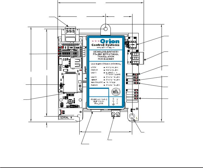
The OE368-23B-BACNET3, PT-Link II BACnet® provides bi-direction- al communication between your BACnet® MS/TP protocol network and up to four* of any of the following types of Orion controllers—VCM-X, VCB-X, RNE, SA, VCM, MUA II, or VAV/CAV:
VCM-X Controller (SS1026, SS1030, SS1032, SS1033,
SS1034, Y200920)
VCB-X Controller (SS1051)
RNE Controller (SS1045)
SA Controller (Y200921)
VCM Controller (SS1016, Y200409, Y200616, Y200822)
**VAV/CAV Controller (SS1003, Y200301) and MUA II Controller (SS1004, Y200405)
To determine what controller you have, you must look at the label located on the controller. NOTE: The label is located on the EPROM on older devices. If the controller label does not match any of the SS or Y numbers listed above, your controller will not work with the PT-Link II BACnet®.
*NOTE: The PT-Link II BACnet® device can be used to connect to four Orion controllers. If more than four Orion controllers are present in a system, you will need additional PT-Link II BACnet® devices.
**NOTE: Documentation is available for MUA II/VAV/CAV on our Orion Controls website: www.orioncontrols.com.
1.1.1 Data Sharing
•Provides values from points on the Orion side of the gateway to BACnet® devices as if the values were originating from BACnet® objects.
•Allows BACnet® devices to modify point values on the Orion controller side of the PT-Link II BACnet® by using standard BACnet® write services.
1.1.2 Scheduling
•Allows BACnet® devices to send Schedule events to the Orion controller side of the gateway by using standard BACnet® services.
1.1.3 Hardware Specifications

 Technical Data
BACnet®-MS/TP Loop |
9600, 19200, 38400, 76800 Mbps |
Controller Loop |
RS-485, 9600 Baud Rate |
|
|
Network Protocol |
BACnet® |
|
|
Protocol |
HSI Open Protocol Token Passing |
(WattMaster Loop) |
|
Power Input Voltage |
24 VAC |
|
|
Power Consumption |
10 VA Maximum |
Operating Temp |
-30°F to 150°F |
|
|
Operating Humidity |
90% RH Non-Condensing |
|
|
Weight |
4.5 oz. |
Table 1: PT-Link II BACnet® Interface
Technical Data
1.1.4 System Requirements
•The PT-Link II BACnet® interface is packaged and assembled for panel mounting. Panel mounting components are included for your convenience.
•Computer running Microsoft WindowsTM operating system.
•Ethernet Crossover Cable (supplied).
•PT-Link II BACnet software—located on included CDROM and downloadable from www.orioncontrols.com.
4 |
PT-Link II BACnet3 Interface |
|
|
2. QUICK PT-LINK SET-UP |
|
|
|
2.1 Quick Start Guide |
|
|
|
|
|
The following steps will get you up and running in no time: |
4. Configure your PT Link DIP Switches. See Section 2.3, page 7. |
||
1. Familiarize yourself with the PT-Link II components (Figure 1). |
• Set the BACnet MS/TP baud rate via the B Bank set of DIP |
||
switches. |
|||
|
|
||
2. Connect your PT-Link II to the Controller(s) on your system (up |
• Set the BACnet MS/TP MAC Address using the PT-Link A |
||
|
to four) and connect your PT-Link II to the BACnet Network |
Bank DIP switches. The BACnet MS/TP MAC Address |
|
|
(Figure 2). NOTE: Controllers must be addressed as |
MUST be set between 1 and 127. |
|
1, 2, 3 & 4. |
|
||
3.Obtain the following from your Building Automation System Integrator: the BACnet MAC address (System Node ID) and the MS/TP network baud rate. Also, relay to your System Integrator that the BACnet Device Instance Number for the PT-Link will be the MAC address + 50,000. If this Device Instance will not work, then continue to the full setup.
|
|
|
4.25 |
|
|
BACnet® |
|
|
|
|
|
Communications |
|
|
|
|
|
Wiring Terminal |
|
2.37 |
1.31 |
|
|
|
|
|
|
485 |
Local Loop |
|
|
IAEZH004 |
Communications |
||
|
|
DRIVER |
|||
|
|
Made in USA |
|||
|
|
RSGND |
|
|
Driver Chip |
|
|
ON |
|
|
|
|
|
O N |
O N |
COMM |
Local Loop |
Configuration |
|
|
|
R |
|
|
1 2 3 4 5 6 7 8 |
1 2 3 4 |
Communications |
||
DIP Switches |
|
|
|
|
|
|
|
|
SH |
Wiring Terminal |
|
|
|
|
|
T |
|
|
|
|
|
|
Communications |
|
|
|
|
|
LED |
4.70 |
4.31 |
|
|
LOOP |
4.82 |
|
|
|
|
||
|
|
|
|
PROTO |
Diagnostic |
|
|
|
|
LED1 |
LED #1 |
BACnet® |
|
|
|
LED2 |
|
|
|
|
|
Diagnostic |
|
Protocessor |
|
|
|
|
|
|
|
|
TIMER |
LED #2 |
|
Module |
|
|
|
||
|
|
|
W_DOG |
|
|
|
|
|
|
|
|
Ethernet |
|
|
|
H-BEAT |
Power |
|
|
|
POWER |
||
Port |
|
|
|
MADE IN USA |
LED |
|
|
|
|
||
|
0.27 |
|
|
|
|
|
|
|
2.61 |
|
0.20 Dia. |
|
|
|
|
|
Mounting Hole |
|
|
|
|
24 VAC Power |
Typ. 3 PL. |
|
|
|
|
|
|
|
|
|
USB |
Terminal |
|
|
|
|
Port |
|
|
Figure 1: PT-Link II BACnet® Dimensions and Components
PT-Link II BACnet3 Interface |
5 |
2. QUICK PT-LINK SET-UP
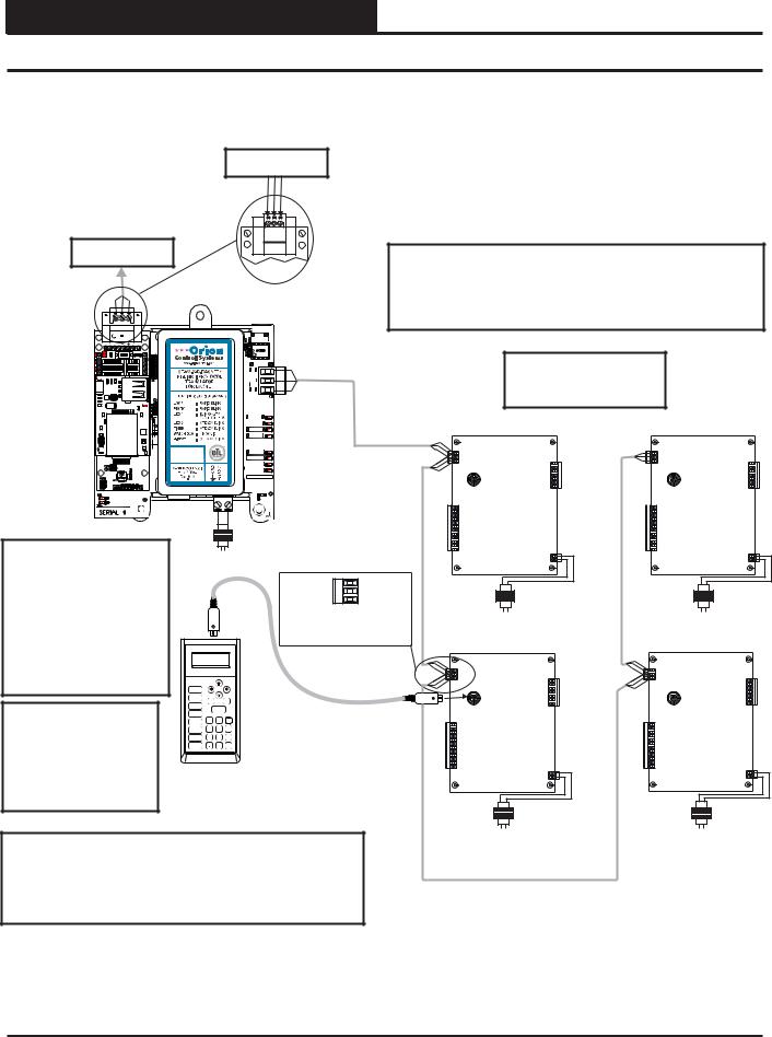
2.2 Connection and Wiring Information
MS/TP Connection
To BACnet® Network
MS/TP Connection |
IMPORTANT WIRING NOTE: |
To BACnet® Network |
|
|
|
Use the Daisy-Chain Topology As Shown in This Diagram. |
|
|
|
PT-Link Interface |
DO NOT Use a Star Topology with Multiple Units Tied |
|
|
|
|
Directly to the PT-Link II. |
|
|
|
485 |
|
|
|
|
DRIVER |
|
|
RSGND |
|
|
|
|
ON |
|
|
|
|
O N |
O N |
COMM |
Up To 4 Controllers |
|
1 2 3 4 5 6 7 8 |
1 2 3 4 |
R |
Can Be Interconnected. |
|
|
|
SH |
Address Controllers |
|
|
|
T |
|
|
|
|
|
As Shown. |
|
|
|
LOOP |
|
|
|
|
PROTO |
Controller |
Controller |
|
|
LED1 |
||
|
|
LED2 |
|
|
|
|
TIMER |
|
|
|
|
W_DOG |
|
|
|
|
H-BEAT |
|
|
|
|
POWER |
|
|
|
|
MADE IN USA |
|
|
Address 1 |
|
Address 2 |
|
|
|
|
|
24 VAC |
|
|
|
|
|
|
(10 VA) |
|
|
Caution: The BACnet® |
|
Line Voltage |
|
|
||
Communication Terminal Block |
|
|
|
|
|
|
Must Be Disconnected Before |
|
|
|
T |
|
|
Connecting The Modular |
|
|
|
SHLD |
24 VAC |
24 VAC |
|
|
|
R |
(8 VA) |
(8 VA) |
|
Service Tool. After |
|
|
|
|||
|
|
|
Typical Terminal Blocks. All |
|
|
|
Programming The |
|
|
|
Line Voltage |
Line Voltage |
|
|
|
|
Wiring To Be T To T, SHLD |
|||
Controller(s), Disconnect The |
|
|
|
|
|
|
|
|
|
(G) To SHLD (G) & R To R |
Controller |
Controller |
|
Service Tool and Then |
|
|
|
|||
|
|
|
|
|||
|
|
|
|
|
|
|
Reconnect The |
|
|
|
|
|
|
Communication Terminal |
|
|
UP |
|
|
|
Block. |
Mode |
PREV |
NEXT |
|
|
|
STATUS |
|
|
|
|||
|
Selection |
|
|
|
|
|
|
SETPOINTS |
|
|
|
|
|
|
|
ESC |
DOWN CLEAR |
|
|
|
|
SCHEDULES |
|
|
|
|
|
Note: All Programming Of |
|
1 |
ENTER |
3 |
|
|
ALARMS |
2 |
|
|
|||
|
OVERRIDES |
|
|
|
|
|
Controllers Must Be Done |
CONFIGURATION |
4 |
5 |
6 |
Address 3 |
Address 4 |
|
|
|
|
|
|
|
Using The Modular Service |
ON |
7 |
0 |
- |
|
|
|
BALANCE - TEST |
8 |
9 |
|
|
|
|
|
DEC |
|
MINUS |
|
|
Tool. The Modular System |
|
|
|
|
|
|
Manager Should Not Be |
Modular Service Tool |
|
|
|||
Used On A System That |
|
|
||||
|
|
|
|
|
|
|
Has A PT-Link Installed. |
|
|
|
|
|
|
|
|
|
|
|
24 VAC |
24 VAC |
|
|
|
|
|
(8 VA) |
(8 VA) |
|
|
|
|
|
Line Voltage |
Line Voltage |
Wiring Notes: |
|
|
|
|
|
|
1.) All wiring to be in accordance with local and national electrical |
|
|
||||
codes and specifications. |
|
|
|
|
|
|
2.) All communication wiring to be 18 gauge minimum, 2 conductor twisted pair with shield. Use Belden #82760 or equivalent.
Figure 2: PT-Link II BACnet® Interface Wiring
6 |
PT-Link II BACnet3 Interface |
2.QUICK PT-LINK SET-UP
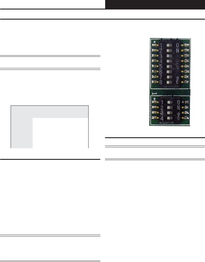
2.3Configuring the PT-Link DIP Switches
The DIP Switches allow you to set the protocol between BACnet MS/TP and BACnet IP, set the BACnet MS/TP Baud Rate, and set the BACnet MS/TP MAC address, and set the BACnet MS/TP device instance. You can obtain the MAC address, Device Instance, and baud rate from your Building Automation System (BAS) Integrator. The DIP Switches are shown in Figure 3.
NOTE: You must cycle power after making changes to the DIP Switch Settings for the settings to take effect.
2.3.1 Set the BACnet MS/TP Baud Rate
“B” bank DIP switches B1 – B4 is used to set the BACnet MS/TP baud rate of the PT-Link. This matches the baud rate required by the Building Management System for BACnet MS/TP.
Using B1 – B4 to Set Baud Rate
Baud |
B1 |
B2 |
B3 |
B4 |
9600 |
ON |
ON |
ON |
ON |
19200 |
OFF |
OFF |
OFF |
ON |
38400 |
ON |
ON |
OFF |
ON |
57600 |
OFF |
OFF |
ON |
ON |
76800 |
ON |
OFF |
ON |
ON |
Table 2: Baud Rate Settings
2.3.2 Set the BACnet MS/TP MAC Address
1.Only (1) MAC address is set for the PT-Link regardless of how many devices are connected to it.
2.Set the BACnet MS/TP MAC addresses of the PT-Link to a value between 1 and 127 (MAC Master Addresses). This is so that the BMS Front End can find the PT-Link via the BACnet auto discovery function. MAC addresses from 128 to 255 cannot be auto discovered by the BMS Front End.
3.Set “A” bank DIP switches A1 – A7 to assign a MAC Address to the PT-Link for BACnet MS/TP. Please refer to Section 9, page 67 for the complete range of MAC Addresses and DIP switch settings.
NOTE: The BACnet Device’s Instance is generated by adding the MAC address to the Node Offset, which defaults to 50,000. If the Device Instance must be set to something other than in the range of 50,001 to 50,127, see Section 3.3.2, page 12 to change the Node Offset value.
FFP-485
DIP
Switch
Bank A 
DIP
Switch
Bank B 
Figure 3: DIP Switches
CAUTION: DIP Switch 8 in Bank A must always remain off for proper operation.
PT-Link II BACnet3 Interface |
7 |

3. PT-LINK CONFIGURATION
3.1 Graphical User Interface
The PT-Link is configured using a Graphic User Interface (GUI) which is a password protected web browser-based interface that uses a combination of technologies and devices to provide a platform from which you can gather and process information. The GUI allows you to do the following:
•Change the BACnet Device Instance to something other than 50,001 to 50,127
•Check the status and diagnostics of the PT-Link,
such as network settings, connection information, node information, map descriptors, and error messages
•Monitor the PT-Link’s internal data and parameters
•Change or update the PT-Link’s internal data and parameters
•Restart the PT-Link
The following items are needed to be able to run the GUI:
•PC Requirements—a computer with a web browser that connects over the Ethernet on port 80*
*NOTE: Computer and network firewalls must be opened for Port 80 to allow the GUI to function.
•Software Requirements—Mozilla Firefox 13.0 and up, Microsoft Internet Explorer 8 & 9**, Google Chrome 19.0 and up, Opera 11 and up, or Safari 4.1 and up
**NOTE: Internet Explorer 8 does have some limitations in terms of graphical features. Some effects such as rounded corners and semi-opaque backgrounds are not supported. So, although technical functionality is operational, the looks might be slightly different
8 |
PT-Link II BACnet3 Interface |
3.PT-LINK CONFIGURATION
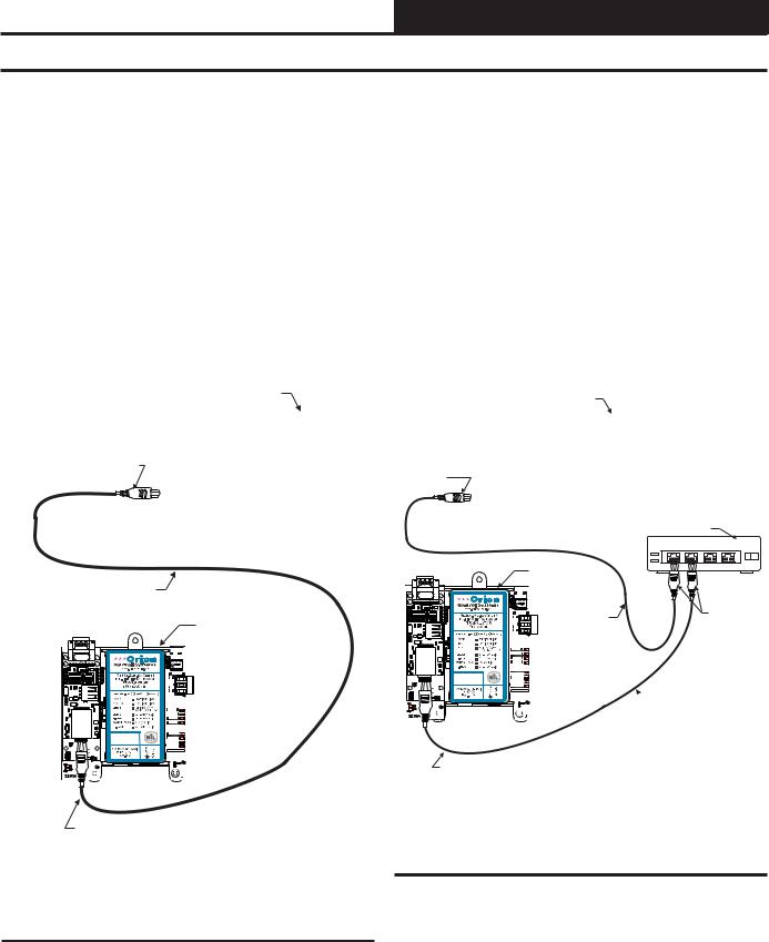
3.2PT-Link II Ethernet Connection
You have two options for connecting the PT-Link II to your PC via Ethernet:
1.) You may connect the PT-Link II directly to your PC by using a standard CAT5 or crossover cable (by others) as shown. See Figure 4 for details.
2.) You can also connect both your PC and the PT-Link II to an Ethernet Hub or Ethernet Switch with standard CAT5 cables. See Figure 5 for details.
Locate a CAT5 cable and plug one end into your computer’s Ethernet port. If connecting directly, plug the other end of the Cable into the Ethernet port on the PT-Link II. If connecting through an Ethernet Hub or Switch, plug the other end of the PC cable into the hub, and use a second CAT5 cable to connect the PT-Link II to the hub as well.
Power up the PT-Link II by plugging in the power cable. The PT-Link II may take up to three minutes to power up completely. Once the PTLink II is powered up, you should notice that the RUN LED is blinking continuously on the ProtoCessor Board. See Figure 28, page 23 for a diagram showing the location of the ProtoCessor RUN LED.
Connect Ethernet
Crossover Cable Directly
To PC Ethernet Card Port
Ethernet Crossover Cable
IAEZH004 |
Made in USA |
Computer
PT-Link BACnet
485 DRIVER
COMM
R
SH
T
LOOP
PROTO
LED1
LED2
TIMER 


W_DOG
H-BEAT
POWER
MADE IN USA
Connect Ethernet
Crossover Cable
To PT-Link Ethernet
Port
Figure 4: Connecting With Crossover Cable
Computer
Connect Ethernet
Cable To
Ethernet
Ethernet Hub
Or Switch
1 |
2 |
3 |
4 |
IAEZH004 |
Made in USA |
|
PT-Link BACnet |
|
485 |
|
|
DRIVER |
|
|
R |
|
Connect |
COMM |
Ethernet Cable |
|
|
Ethernet |
|
SH |
|
|
T |
|
|
|
|
Cables To |
LOOP |
|
Ethernet Hub |
PROTO |
|
Ports |
LED2 |
|
|
LED1 |
|
|
 TIMER
TIMER 


W_DOG
 H-BEAT

POWER
MADE IN USA
 Ethernet Cable
Connect Ethernet
Crossover Cable
To PT-Link Ethernet
Port
Figure 5: Connecting With Ethernet Cable & Hub
PT-Link II BACnet3 Interface |
9 |

3. PT-LINK CONFIGURATION
3.3 IP Address Configuration
3.3.1 Computer IP Address Set-up for Windows XP, Vista, 7 & 8
In order for the PT-Link II to communicate properly, it is imperative to set the IP address of both the PT-Link II as well as the computer to be within the same netmask. You need to change the IP address on your computer. The following instructions will explain how to configure the IP address for Microsoft® Windows XP, Vista, 7, and 8 operating systems.
3.3.1.1 Computer IP Address Set-up for Windows NT & XP
1.) Click <start>; then click <Control Panel>.
2.) Double-click on the Network Connections icon. The Network Connections Window will appear (Figure 6).
Figure 6: Network Connections Window
Figure 7: Local Area Connection Status Window
4.) As shown in Figure 7, click <Properties> in the lower left of the window. The Local Area Connection Properties Window will appear.
NOTE: If any wireless connections are listed, disable them by right-clicking the connection and selecting
<Disable>.
3.) In the Network Connections Window, double-click the
Local Area Connections entry. The Local Area Connection Status Window will appear (Figure 7).
Figure 8: Local Area Connection Properties Window
5). As shown in Figure 8, in the Connection Items list box, be sure the Internet Protocol (TCP/IP) is checked. Select the Internet Protocol (TCP/IP) item to highlight it and then click
<Properties>. The Internet Protocol Properties Window will appear.
10 |
PT-Link II BACnet3 Interface |
3.PT-LINK CONFIGURATION
3.3IP Address Configuration
Figure 9: Internet Protocol Properties Window
6). Select the radio button in front of Use the following
IP address (Figure 9) and write down the current defaults so that you can re-enter them when you finish configuring the PT-Link and then type in the following
information:
a.) |
IP address 192.168.1.5 |
b.) |
Subnet mask 255.255.255.0 |
c.) |
Default Gateway is blank |
7.) Click <OK> until all of the above network configuration windows are closed. You may have to reboot the computer before the new values are valid.
3.3.1.2 Computer IP Address Set-up for Windows Vista, 7 & 8
1.) Click <start>; then click <Control Panel> (Vista & Windows 7). Click <start>; then right-click for <All apps>.
Click <All apps> and then click <Control Panel>
(Windows 8).
2.) Click on the Network and Internet icon.
3.) Click Network and Sharing Center.
4.) From the shaded box in the left side of the window, select
Manage Network Connections (Vista) or Change adapter settings (Windows 7).
5.) Right-click on the Local Area Connection icon and select
<Properties> for the drop down window.
6.) Choose Internet Protocol Version 4 (TCP/IPv4) by highlighting it and then click <Properties>. The Internet Protocol Properties Window will appear (Figure 9).
7.) Select the radio button in front of Use the following
IP address (Figure 9) and write down the current defaults so that you can re-enter them when you finish configuring the PT-Link and then type in the following
information:
a.) |
IP address 192.168.1.5 |
b.) |
Subnet mask 255.255.255.0 |
c.) |
Default Gateway is blank |
8.) Click <OK> until all of the above network configuration windows are closed. You may have to reboot the computer before the new values are valid.
PT-Link II BACnet3 Interface |
11 |
3. PT-LINK CONFIGURATION
3.3IP Address Configuration
3.3.2BACnet MS/TP - Setting Node_ Offset to Assign Specific Device Instances
After setting your PC to be on the same subnet as the PT-Link, open a web browser on your PC and enter the IP address of the PT-Link; the default address is 192.168.1.24. (Figure 10).
1.If the IP address of the PT-Link has been changed by previous configuration, you will need to get the assigned IP address from the network administrator or use the FieldServer ToolBox to find the IP Address.
2.The configuration page will be displayed as your landing page. (Figure 10)
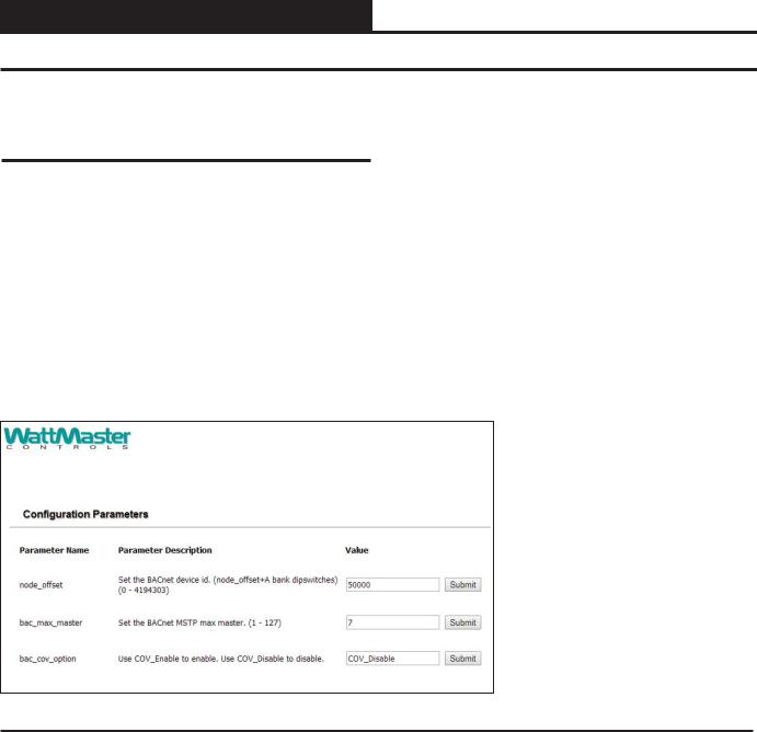
3.The node offset can be changed on the configuration page.
Figure 10: BACnet MS/TP Settings for Node_Offset
4.The Node_Offset field will be presented displaying the current value (default = 50,000).
5.Change the value of Node_Offset to establish the desired Device Instance value, and click <Submit>.
Device Instance = |
Node_Offset + |
|
A bank DIP switch setting |
|
(A1-A7) |
12 |
PT-Link II BACnet3 Interface |

3.PT-LINK CONFIGURATION
3.4Changing the Config.csv File
NOTE: You may need Administration rights to perform this function. See the Password Section, page 65.
3.) Refer to the File Transfer Window below (Figure 13). In the Configuration Tab, under Retrieve, click the config.csv file in order to save it to a destination and then open it.
1.) Open your web browser, and type the IP Address of the PT-Link, which defaults to <192.168.1.24>, and press <ENTER>. The GUI will launch. See Figure 11.
Figure 11: The FS-GUI Main Screen
2.) In the Navigation Window on the left of the FS-GUI Screen, click
<Setup> and then click <File Transfer>. See Figure 12.
Figure 12: Navigation Window - File Transfer
Figure 13: File Transfer - Configuration Tab
4.) Open the config.csv file in Notepad. See Figure 14.
WARNING: Only edit the config.csv file using Notepad. DO NOT use Excel. Using Excel to edit the config.csv file will corrupt its contents!
Figure 14: Config.csv File
PT-Link II BACnet3 Interface |
13 |
3. PT-LINK CONFIGURATION
3.4 Changing the Config.csv File
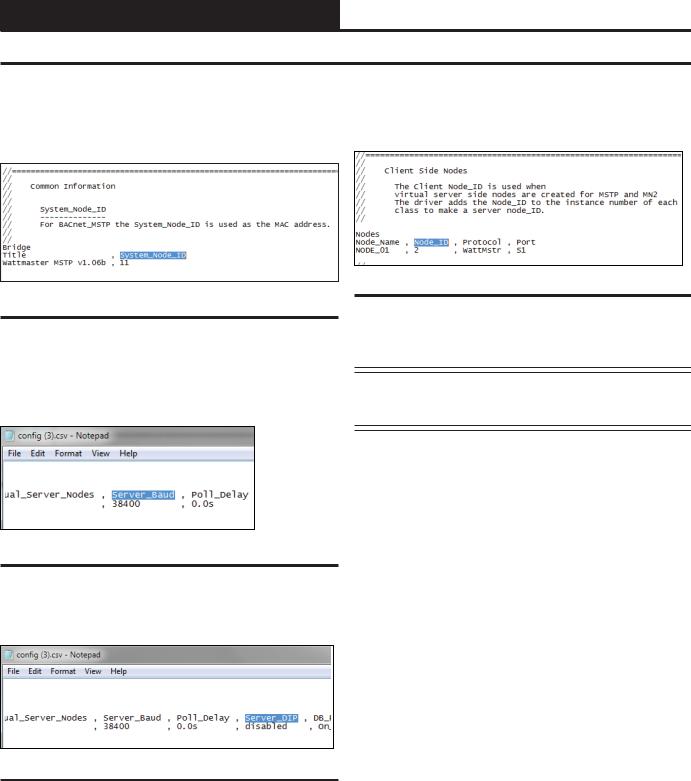
5.) Near the top of the text file under ‘System_Node_ID’, change the BACnet MAC address from the default of 11 (Figure 15). You can obtain this address to enter from your Building Automation System (BAS) Integrator.
8.) The last change you may need to make is the Node_ID under ‘Client Side Nodes’which is the BACnet Device Instance Number (Figure 18). The default is 1.You can obtain the Node ID from your BAS Integrator.
Figure 15: System Node ID
6.) If you need to change the server baud rate, under ‘Connections’, change the Server_Baud (Figure 16). Possible Baud Rate values are (9600, 19200, 38400, and 76800). The default Baud Rate is 38400. You can obtain the correct baud rate from your BAS Integrator.
Figure 16: Server Baud Rate
Figure 18: Client Node ID
9.) Once all changes have been made to the text file, while still in Notepad, click <File> in the upper left and then click <Save>. Now close the file and return to the FS-GUI Screen open in your browser.
NOTE: Do not rename the file. The file must always be named “config.csv”; otherwise, it will be ignored by the PTLink.
7.) Inside the text file under ‘Connections’, change the ‘Server_DIP’ parameter from ‘Enabled’ to ‘Disabled’. (See Figure 17).
Figure 17: Server Dip Switch
14 |
PT-Link II BACnet3 Interface |
3.PT-LINK CONFIGURATION
3.4Changing the Config.csv File
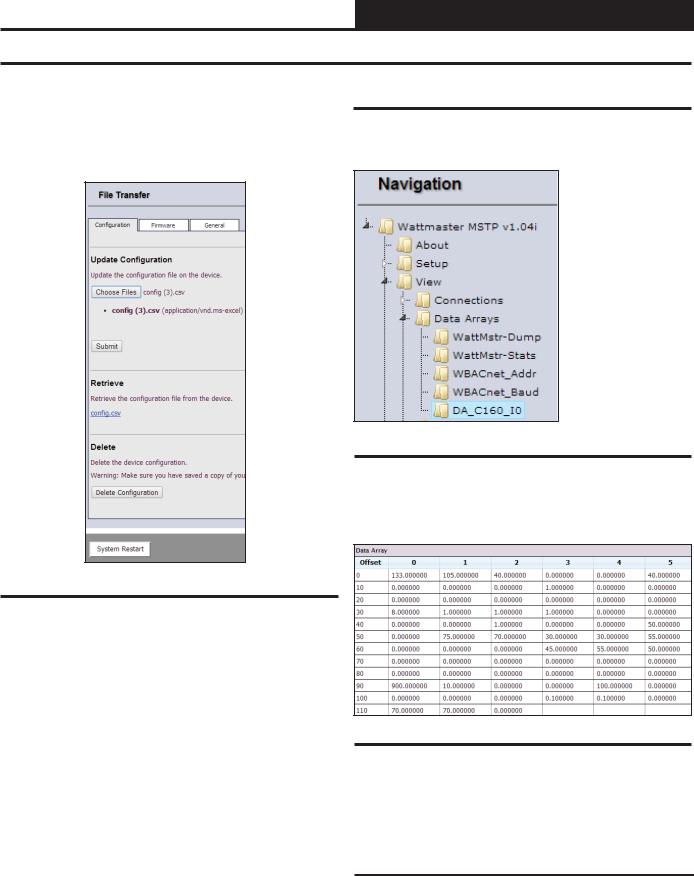
10.) In the File Transfer Window under Update Configuration, click <Choose Files> or <Browse>and locate the config.csv file you just saved. Then click <Submit>. See Figure 19. Wait until the message, “Configuration update complete” appears and then click the <System Restart> button at the bottom of the File Transfer Window to activate the new configuration file.
3.4.1 Verifying Communications
1. ) In the Navigation Window on the left of the FS-GUI Main Screen, click <View> and then click <Data Arrays>. See Figure 20.
Figure 20: Navigation Window - View Data Arrays
2. ) Click on the Controller name. In this case, it is DA_C160_I0, a VCM-X Controller. The Controller’s Data Array Table will display. See Figure 21.
Figure 19: Update Configuration
NOTE: The following files can also be udpated in File Transfer Window:
Firmware Files: The FieldServer Firmware contains the application program commonly referred to as the DCC or the PCC. This program contains the protocol drivers applicable to the application and the FieldServer Operating System Kernel. A Firmware update is only required when updated files are received from FieldServer support. Firmware files have a *.bin extension. The procedure for updating these is the same as for the configuration files, but the update needs to be made in the Firmware Tab.
General (Other) Files: Other files that can be updated include the FSGUI image and other files described in driver manuals. The procedure for updating these is the same as for the configuration files, but the update needs to be made in the General Tab.
Figure 21: VCM-X Data Array Table
3 ) You can now cross reference the values shown in Figure 21 with the listed parameter names in the appropriate Data Array Table for your controller type. These tables can be found on pages 28-31.
3.4.2 FS-GUI Reference Guide
An FS-GUI Reference Guide can be found in Section 8, page 64.
PT-Link II BACnet3 Interface |
15 |
4. UPDATING THE SOFTWARE
4.1 Updating the PT-Link II Controller
4.1.1 Programming the PT-Link II with BootLoader
The PT-Link II is equipped with the ability to update its software with the use of a computer. You will need the following before you begin:
•PT-Link II in need of an update (powered up, no other connections necessary)
•Computer running Microsoft WindowsTM operating system
•Prism 2 software from www.orioncontrols.com
•Latest version of PT-Link II software (e-mailed from our tech support staff or downloaded from any of our websites) and software sheet
•USB Driver Setup.exe file from PT-Link II CD or downloaded from any of our websites.
•USB cable
Follow these simple steps to update the PT-Link II:
1.) Turn on your computer and download the latest Prism 2 software from www.orioncontrols.com.
2.) Either download the PT-Link II update file from http://techsupport. wattmaster.com or save the file to your computer from the e-mail you received from Tech Support. Record the path and name of the file for later use. Also, print the software sheet provided for future reference.
3.) Run the USB Driver Setup.exe file (found on the PT-Link II CD or downloaded from any of our websites) so that Prism can communicate to the PT Link II. Unzip the file to the directory where you saved your PT-Link II software.
4.) Plug the USB cable into the computer’s and PT-Link II’s USB ports.
5.) A message will pop-up from the lower menu bar of Windows that reads, “Found New Hardware.” Click on this message and follow the instructions that appear to install the USB drivers.
6.) Open Prism 2 and Login with the User Name, admin and the Password, admin. If successful, “Administrator Access” will appear at the lower right of the Prism program. NOTE: If using a Prism 2 version prior to 4.0, the Login is flash. If successful, “Level 4 Access” will appear at the lower right of the Prism program.
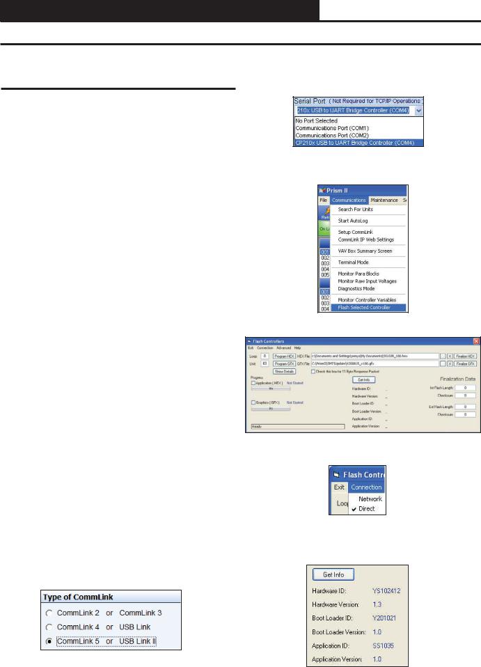
7.) Click on the <Job-Site> icon. The Job-Sites Window will appear. In the Type of CommLink Dialog Box, select “CommLink 5.”
8.) In the Job-Sites Window, from the Serial Port drop down list, select the correct COM port. If you don’t know the COM port number or if the number is 10 or higher, follow the directions on pages 18 and 19.
9.) From Prism 2’s Communications tab, select “Flash Selected Controller.”
10.) The Flash Controller Window will appear.
11.) From the Flash Controller Window’s Connection tab, select “Direct”. Keep the Flash Controller Window open.
12.) Cycle power to the PT-Link II and within 5 seconds, click the <Get Info> button in the Flash Controller Window. The PT-Link II information will now appear in the window under the <Get Info> button.
16 |
PT-Link II BACnet3 Interface |

4.UPDATING THE SOFTWARE
4.1Updating the PT-Link II Controller
13.) The Application ID should be SS1035 and the Application Version should match the software version you will be updating to.
14.) In the HEX File field, enter the path and name of the HEX file you downloaded and/or copied to your hard drive. Use the Browse button (...) to the right of the field if you need help in locating the file.
15.) Now, cycle power to the PT-Link II once again and within 5 seconds click on the <Program HEX> button (shown above). If successful, you should see the Progress Application HEX bar showing the progress percentage.
16.) When the bar shows 100% completed, verify the PT-Link II’s software is running by observing the Timer LED blinking.
17.) Verify the PT-Link II’s Application Version by once again cycling power to the PT-Link II and within 5 seconds clicking the <Get Info> button.
18.) Verify all fields are correct in the information below the <Get Info> button and under “Finalization Data.” The “Int Flash Length” and “Checksum” values should match the values provided with the software sheet.
PT-Link II BACnet3 Interface |
17 |
4. UPDATING THE SOFTWARE
4.1 Updating the PT-Link II Controller
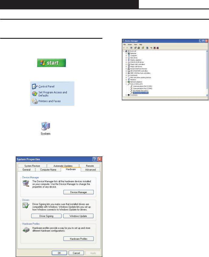
4.1.2 Finding What COM Port Number the PT-Link II is Using
1.Left-click on <Start>, located on the bottom left of the Windows Tool Bar.
2.Select <Control Panel>.
3.Double-click the System Icon.
4.Click the <Hardware> tab.
5.Click the <Device Manager> button.
6.Click on the plus sign next to Ports to see all of the common ports.
7.Locate the USB Serial Port (COM#). The COM# in parentheses is the port it is located on. Write this COM port number down. You will need to know this when setting up the Prism software.
8.If the COM port number is 10 or greater, go to “Changing the USB COM Port Number” on page 19.
18 |
PT-Link II BACnet3 Interface |
4.UPDATING THE SOFTWARE
4.1Updating the PT-Link II Controller
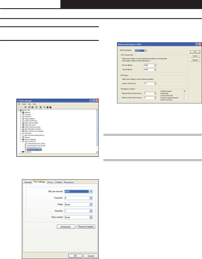
4.1.3 Changing the USB COM Port
Number
4.To assign a port number less than 10, click on
<Advanced>. The Advanced Settings Window will appear.
When the PT-Link II is first plugged in, it will be assigned a COM port number to be used for communicating with the Prism software. If the port number is 10 or greater, it needs to be changed to a value less than 10 to be recognized by Prism.
1.Click <Start>, click <Control Panel>, click <System>, click the <Hardware> tab, and then click <Device Manager> to get to the Device Manager Window.
2.Click on the plus sign next to Ports to see all of the COM ports.
3.Right-click on “USB Serial Port (COM#)” and select
<Properties>. In the Properties Window, select the
<Port Settings> tab.
5.In the COM Port Number drop box, select which COM port you wish to use. Make sure you select a COM port number that is not currently in use (you can see the ports in use in the Device Manager Window). Select a port that is less than 10.
NOTE: Windows® will assign a port number to every device that has ever been installed on your computer. So if there are no available ports below 10, choose a port number less than 10 for a device listed that you know you are not currently using.
6.Once you select the correct COM port number, click <OK> and close any windows opened in the process of changing the port number. Make note of this number because you will need it for your Prism setup.
PT-Link II BACnet3 Interface |
19 |
4. UPDATING THE SOFTWARE
4.2 Updating the Field Server Software
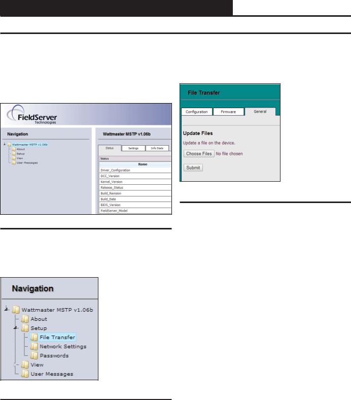
1.) Extract and save the update file you receive from Field Server onto your PC.
2.) Open your web browser, and type the IP Address of the PT-Link, which defaults to <192.168.1.24>, and press <ENTER>. The GUI will launch. Click <Diagnostic and Debugging>. The Main Screen will appear. See Figure 22.
4.) Refer to the File Transfer Window below (Figure 24). In the General Tab, click <Browse> and locate the file you saved in Step 1. Then click on <Submit>. When the download is complete, click on the <System Restart> button.
Figure 24: File Transfer - General Tab
Figure 22: The FS-GUI Main Screen
3.) In the Navigation Window on the left of the FS-GUI Screen, click
<Setup> and then click <File Transfer>. See Figure 23.
Figure 23: Navigation Window - File Transfer
20 |
PT-Link II BACnet3 Interface |
5. TROUBLESHOOTING
5.1 Troubleshooting Communications
5.1.1 Check Wiring and Settings |
|
5.1.2 Verifying Communications |
No COMS on WattMaster side
If TX/RX are not flashing rapidly, then there is a COM issue on the WattMaster side and you need to check the following things:
•Visual observations of LEDs on ProtoNode. (Figure 28, page 23)
•Check baud rate, parity, data bits, stop bits
•Check WattMaster device address
•Verify wiring
•Verify all the WattMaster devices that were discovered in FST Web Configurator. (page 12)
NOTE: If the problem still exists, a Diagnostic Capture needs to be taken and sent to WattMaster Technical Support. See page 26.
Field COM problems
•Visual observations of LEDs on PT-Link. (Figure 27, page 22)
•Visual dipswitch settings (using correct baud rate and device instance)
•Verify IP address setting
•Verify wiring
NOTE: If the problem still exists, a Diagnostic Capture needs to be taken and sent to WattMaster Technical Support. See page 26.
1. ) In the Navigation Window on the left of the FS-GUI Main Screen, click <View> and then click <Data Arrays>. See Figure 25.
Figure 25: Navigation Window - View Data Arrays
2. ) Click on the Controller name. In this case, it is DA_C160_I0, a VCM-X Controller. The Controller’s Data Array Table will display. See Figure 26.
Figure 26: VCM-X Data Array Table
3 ) You can now cross reference the values shown in Figure 26 with the listed parameter names in the appropriate Data Array Table for your controller type. These tables can be found on pages 28-31.
PT-Link II BACnet3 Interface |
21 |

5. TROUBLESHOOTING
5.2 Troubleshooting LEDs
5.2.1 PT-Link II Board LEDs
The PT-Link II BACnet® is equipped with LEDs that can be used for troubleshooting. There are eight LEDs on the PT-Link board. See Figure 27 for the locations of the LEDs on the PT-Link board. The LED descriptions and functions are listed in the following paragraphs.
POWER LED
When the PT-Link II BACnet® is powered up, the “POWER” LED should light up and stay on continuously. If it does not light up, check to be sure that you have 24 VAC connected to the board, that the wiring connections are tight, and that they are wired for correct polarity. The 24 VAC power must be connected so that all ground wires remain common. If after making all these checks the “POWER” LED still does not light up, please contact WattMaster Controls Technical Support at our Toll Free number—866-918-1100—for assistance.
LOOP LED
When power is applied to the PT-Link II BACnet®, the “LOOP” LED will also light up. The LED should flicker rapidly, indicating that the PT-Link is trying to communicate with the controllers on the loop. A “flicker” is defined as a brief moment when the LED turns off and back on. If the “LOOP” LED does not operate as indicated above, first power down the unit and then reapply power. If this does not work, please contact WattMaster Controls Technical Support at our Toll Free number—866-918-1100—for assistance.
LED 1
When power is first applied, “LED 1” will be off temporarily and then will blink one time for each controller it is communicating with. For example, if you have 4 controllers on the loop connected to the PT-Link, “LED 1” will blink 4 times. If the amount of blinks does not match the number of controllers connected to the loop, it indicates there is a communications problem. The best way to find out which board is not communicating is to go to each controller and look at its “COMM” LED. The “COMM” LED should be solid and will flicker occasionally indicating communication with the PT-Link II BACnet®. If the “COMM” LED does not flicker, there is no communication with that controller.
LED 2
When power is first applied, “LED 2” will be off temporarily and then will blink slowly indicating that the PT-Link baseboard is communicating with the ProtoCessor Module. If “LED 2” does not blink, check that the ProtoCessor Module is installed correctly on the PT-Link baseboard and that the “PWR” LED is lit up on the ProtoCessor Module.
PROTO LED
When the PT-Link II is first powered up, the “PROTO” LED should blink rapidly and may appear to be on solid. This LED verifies communication with the board and the ProtoCessor. If the LED doesn’t light up, check that the ProtoCessor is installed correctly and firmly connected to the Base Board. The “PWR” LED should also be lit on the ProtoCessor Module.
TIMER LED
The “TIMER” LED is used for troubleshooting by WattMaster Controls Technical Support. The “TIMER” LED should always be blinking steadily.
Figure 27: PT-Link II BACNET® LED Locations
WATCH DOG LED
The “W-DOG” LED is used for troubleshooting by WattMaster Controls Technical Support. The “W-DOG” LED should always be on solid.
HEARTBEAT LED
The “H-BEAT” LED blinks to show the PT-Link II board software is running. If the LED doesn’t light up, and all other checks have been made, please contact WattMaster Controls Technical Support at our Toll Free number—866-918-1100—for assistance.
22 |
PT-Link II BACnet3 Interface |
 Loading...