


www.orioncontrols.com
VCC-X Controller
Operator Interface SD
Technical Guide
VCC-X Controller Code: SS1062 Version 2.0 & up VAV/Zone Controller Code: SS1001, SS1005, SS1025 Requires Service Tool SD Code: SS1063 Requires System Manager SD Code: SS1068

IMPORTANT NOTICE
This technical guide provides instructions for using the Modular Service Tool and Modular System Manager SD with the VCC-X & VAV/Zone Controllers only. If you are using a different controller, you can download the applicable SD Technical Guide listed below from our website— orioncontrols.com. The technical guides can also be printed from the SD card.
VCB-X Controller - OR-VCBXIOSD-TGD
VCM-X & VCM-X E-BUS Controller - OR-VCMXRNEOISD-TGD RNE Controller - OR-VCMXRNEOISD-TGD
SA E-BUS Controller - AA-SAOISD-TGD VCM Controller - OR-VCMOISD-TGD
VAV/CAV and MUA II Controllers - OR-VAVCAVMUAOISD-TGD
SD CARD UPDATING INSTRUCTIONS
The Modular Service Tool and Modular System Manager are equipped with an SD memory card. This SD card can be removed and easily updated through a computer by downloading updates, as they become available, from our website to your computer.
In order to perform any updates, your computer needs an SD card drive or you will need to purchase an SD card adapter.
Download instructions are found in Appendix B on page 85 of this manual.
www.orioncontrols.com
WattMaster Controls, Inc. |
AAON® is a registered trademark of AAON, Inc., Tulsa, OK. |
8500 NW River Park Drive · Parkville, MO 64152 |
WattMaster Controls, Inc. assumes no responsibility for |
Toll Free Phone: 866-918-1100 |
errors or omissions. |
PH: (816) 505-1100 · FAX: (816) 505-1101 |
This document is subject to change without notice. |
E-mail: mail@wattmaster.com |
Form: OR-VCCXOISD-TGD-01A |
Visit our website at www.orioncontrols.com |
Copyright June 2015 WattMaster Controls, Inc. |
|
|

TABLE OF CONTENTS
OVERVIEW & SYSTEM CONNECTION............................................................................... |
4 |
Modular Service Tool ............................................................................................................................... |
4 |
Modular System Manager SD ................................................................................................................. |
6 |
MODULAR SERVICE TOOL SD ........................................................................................ |
10 |
Display Screens and Data Entry Keys................................................................................................... |
10 |
Initialization & Setting the Time & Date ................................................................................................. |
11 |
Setting the Operating Mode & Energy Timer......................................................................................... |
12 |
Alarm Search & Override Search .......................................................................................................... |
13 |
Schedules & Holidays............................................................................................................................ |
14 |
Schedule Override................................................................................................................................. |
15 |
SYSTEM MANAGER SD ................................................................................................... |
16 |
Display Screens and Data Entry Keys................................................................................................... |
16 |
Initialization & Setting the Time & Date ................................................................................................. |
17 |
Setting the Operating Mode................................................................................................................... |
18 |
Changing Passcodes............................................................................................................................. |
19 |
Loop Search and System Alarm Search................................................................................................ |
20 |
Unit Alarm Search & Override Search ................................................................................................... |
21 |
Schedules & Holidays............................................................................................................................ |
22 |
Schedule Override................................................................................................................................. |
23 |
PROGRAMMING............................................................................................................... |
24 |
VCC-X Configuration Screen Index....................................................................................................... |
24 |
VCC-X Configuration ............................................................................................................................. |
25 |
VCC-X Setpoint Screen Index ............................................................................................................... |
39 |
VCC-X Setpoint Configuration............................................................................................................... |
40 |
VCC-X Status Screen Index .................................................................................................................. |
54 |
VCC-X Status Screens .......................................................................................................................... |
55 |
RSMV Configuration.............................................................................................................................. |
64 |
RSMV Status ......................................................................................................................................... |
67 |
VAV/Zone Configuration Screens .......................................................................................................... |
69 |
VAV/Zone Setpoint Screens .................................................................................................................. |
72 |
VAV/Zone Status Screens ..................................................................................................................... |
76 |
VAV/Zone Damper Force Modes........................................................................................................... |
78 |
MiniLink PD Configuration Screens....................................................................................................... |
79 |
MiniLink PD Status Screens .................................................................................................................. |
80 |
TROUBLESHOOTING....................................................................................................... |
81 |
VCC-X Outputs Force............................................................................................................................ |
81 |
APPENDIX A - SAVING, LOADING, AND COPYING SETPOINTS ..................................... |
83 |
APPENDIX B - UPDATING YOUR SD MEMORY CARD ..................................................... |
85 |
APPENDIX C - UPDATING CONTROLLERS & E-BUS MODULE SOFTWARE.................... |
86 |
INDEX .............................................................................................................................. |
88 |
VCC-X Operator Interface SD |
3 |
SYSTEM CONNECTION
Modular Service Tool SD
Modular Service Tool SD
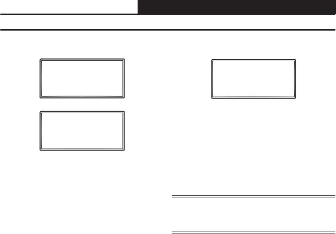
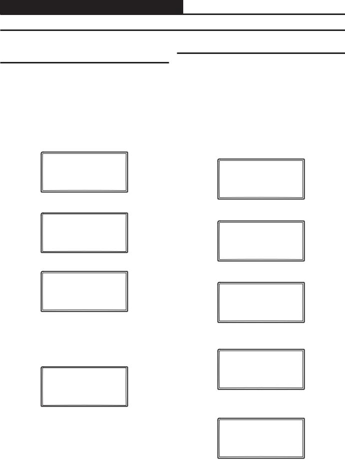
The OE391-12 Modular Service Tool is a system operator interface that provides a direct link to enable the system operator to view the status, configure, and adjust the setpoints of the VCC-X, VBC-X, VCM, VCM-X, VCM-X E-BUS, RNE, SAE-BUS, VAV/CAV, MUA II, or VAV/Zone Controller on the control system communications loop. However, this manual only applies to VCC-X and VAV/Zone Controllers. See note in the inside front cover for the list of manuals that pertain to other controllers.
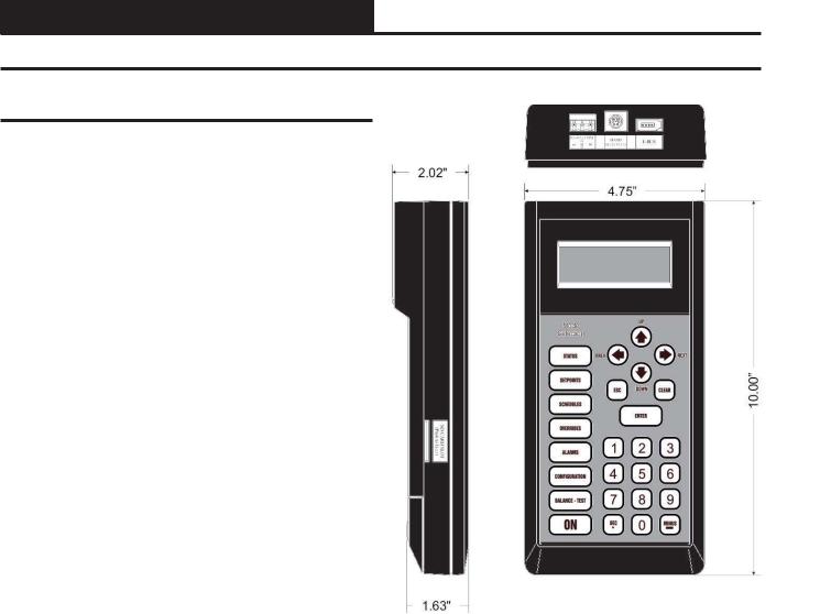
The Modular Service Tool is housed in an attractive black plastic enclosure. The display area is covered with a clear plastic bezel for protection of the display screen. The Modular Service Tool has a 4-line-by-20-character display panel with adjustable contrast control and a 27-key membrane keypad for data selection and entry. All keypad operations are simple and straight forward, utilizing noncryptic plain English language messages. Menu-driven programming allows for easy setup and operation without the need for specialized training. The Modular Service Tool is supplied with a programmable 4 Gigabyte SD memory card, (4) AA 1.5 V batteries, a wall mount, a DC power supply, a mini-Din communication cable, and an E-BUS communication cable. The mini-Din cable allows you to connect the Modular Service Tool to any Orion controller which has a mini-Din connector socket for programming, monitoring, and troubleshooting purposes.
The Modular Service Tool is also equipped with an EBC E-BUS port and an RS-485 three conductor terminal block port. The E- BUS port and included E-BUS cable are used for updating E-BUS Module software (described in Appendix C). The RS-485 port is used for hard-wiring to older controllers that do not have a mini-DIN connector socket.
The Modular Service Tool is designed to be hand-carried. Its rug- |
Figure 1: Modular Service Tool SD Dimensions |
ged plastic housing provides superior protection for the electronic |
|
components housed inside. The Modular Service Tool is a top-quality |
|
service tool that will stand up to the demands of the typical job site |
|
environment for many years. |
|
4 |
VCC-X Operator Interface SD |
SYSTEM CONNECTION
Modular Service Tool
Modular Service Tool
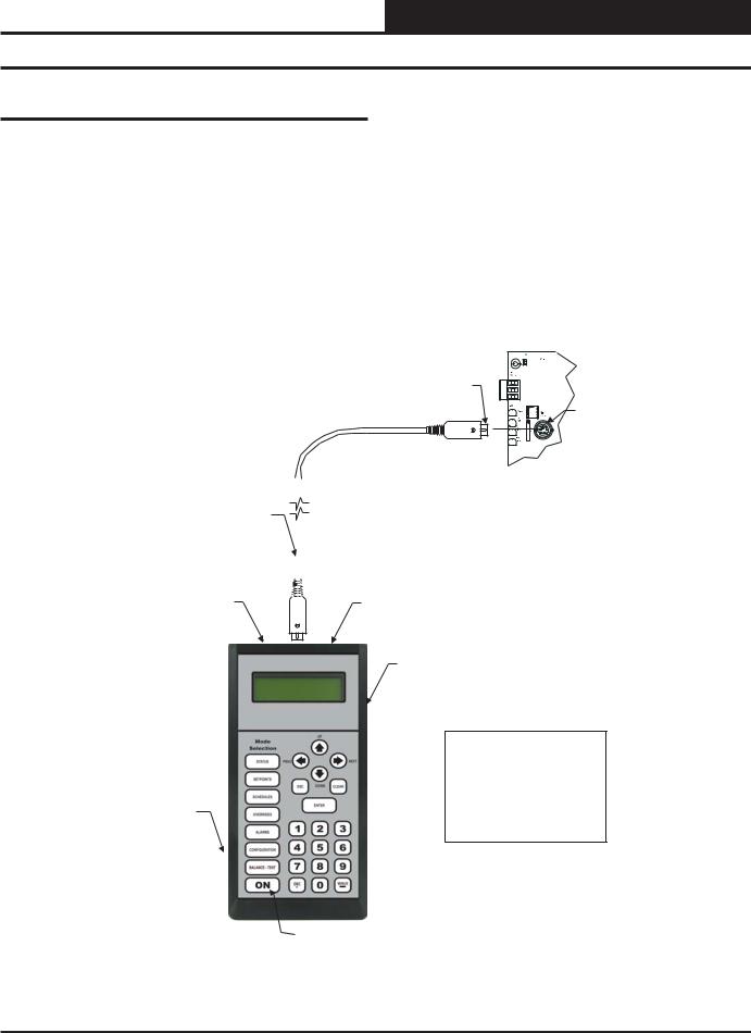
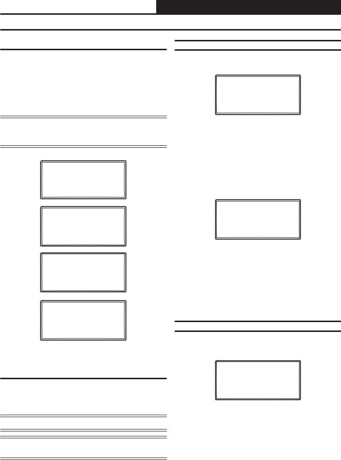
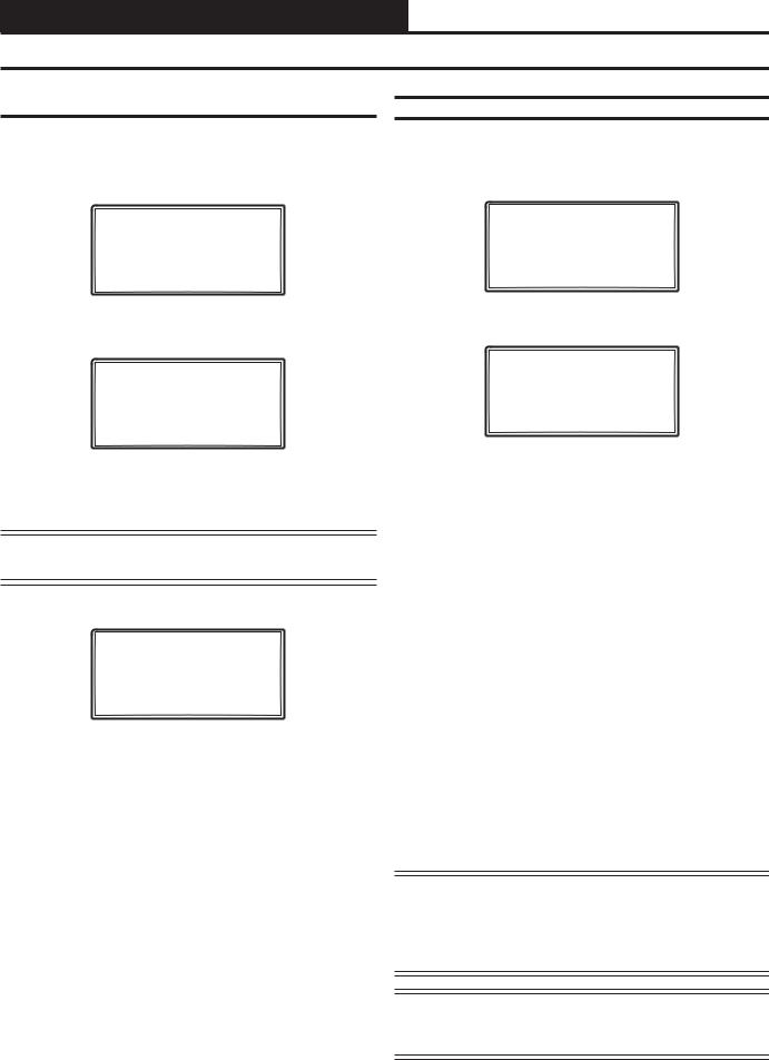
Whether you have a Stand Alone, Interconnected, or Networked VCC-X Control System, the Modular Service Tool always connects to the controller via a prefabricated cable that is supplied with the service tool. The Modular Service Tool cable is terminated on both ends with a mini-DIN connector. Attach one end to the Modular Service Tool and the other end to the mini-DIN connector on the controller. If this is an Interconnected System, all controllers that are interconnected with communications cable can be programmed from any controller on the loop. If this is a Networked System, all controllers on the entire Networked System can be programmed from one controller.
Be sure that the Modular Service Tool has fresh batteries installed or that it is connected to a power source using the supplied power pack before attempting any programming of the controller. See Figure 2 for connection details.
Male DIN Connector
Female DIN
Connector
Connector Cable |
|
|
|
Typical Controller Board |
|
|
|
|
|||
|
|
|
|
||
|
|
|
|
||
|
|
|
The Modular Service Tool Can Be |
||
|
|
||||
|
|
|
|
Connected To A Unit Controller |
|
|
|
|
|
Or VAV/Zone Controller By |
|
|
|
|
|
Plugging One End Of The |
|
|
|
|
|
Supplied Cable Into the |
|
|
|
|
|
Modular Service Tool DIN |
|
|
|
|
|
Connector And The Other End |
|
|
|
|
|
Into The DIN Connector On The |
|
RS-485 |
EBC |
||||
Controllers. |
|||||
Port |
E-BUS |
|
|||
|
|||||
Port
Modular Service Tool SD
Be Sure The Modular Service Tool Is Connected To The Supplied Power Pack Or Has Fresh Batteries Installed Before Attempting Programming Of The
Controller. Be Sure The Power Is SD Memory Card Turned Off On The Modular
Service Tool Before Connecting The Cable To The Controller.
Power On Button
Figure 2: Modular Service Tool SD
VCC-X Operator Interface SD |
5 |
SYSTEM CONNECTION
Modular System Manager SD
Modular System Manager SD
9.00"
UP |
STATUS |
6.25" |
|
|
1 |
2 |
3 |
|
SETPOINTS |
|
|
|
|
|
|
5 |
PREV |
|
NEXT |
4 |
6 |
|
SCHEDULES |
|
7 |
8 |
9 |
ESC DOWN CLEAR |
OVERRIDES |
DEC |
0 |
- |
|
|
|
MINUS |
ENTER |
ALARMS |
1.81"
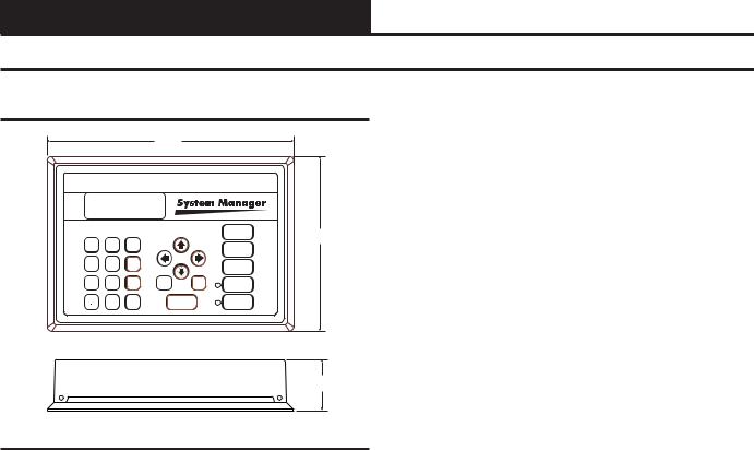
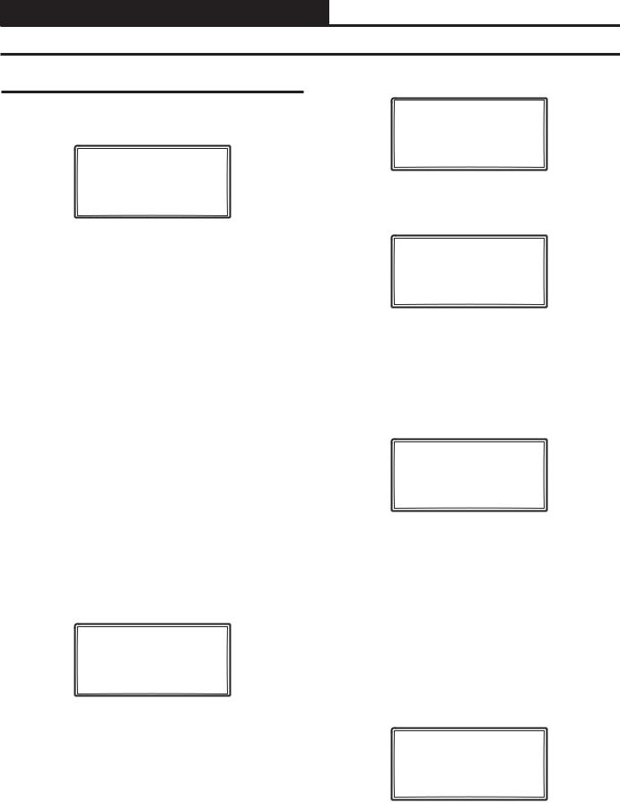
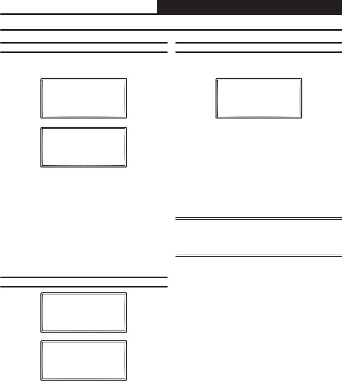
Figure 3: Modular System Manager SD Dimensions
The OE392-12 Modular System Manager SD provides a direct link to enable you to view the status and adjust the setpoints of the VCC-X, VCB-X, VCM-X, VCM-X E-BUS, RNE, SAE-BUS, VCM, VAV/CAV, MUA II or VAV/Zone Controller on the control system communications loop. The System Manager SD is housed in a beigecolored plastic enclosure. The System Manager has a programmable 4 Gigabyte SD card and is equipped with a 4-line-by-20-character backlighted display panel and a 24-key membrane keypad for data selection and entry. All keypad operations are simple and straight forward, utilizing non-cryptic plain English language messages. Menu-driven programming allows for easy setup and operation without the need for specialized training. The System Manager also has 2 integral LEDs for user notification of system alarm conditions and override initiations. Protection from unauthorized users is provided by the System Manager’s integral multi-level passcode authorization programming.
On a Networked System, the Modular System Manager is connected to the communications and power loop of the system via modular cables that simply plug into the System Manager board and the Power/Comm Distribution Board. This virtually eliminates wiring errors and makes installation fast and easy. When it is to be connected to a Stand-Alone system, a cable with modular connectors on one end and stripped wire ends on the other end is provided to facilitate connecting communications and power to the Modular System Manager from the 24 VAC power source and the HVAC unit controller communication wiring terminals.
The Modular System Manager is designed for wall mounting. Mounting holes are provided to attach the Modular System Manager to a standard handy box. It is recommended that the System Manager be mounted at approximately eye level to allow for ease of programming and reading of the display. The System Manager is typically mounted in the building manager’s or superintendent’s office or in an equipment room. The attractive enclosure is quite suitable for mounting in any location.
6 |
VCC-X Operator Interface SD |
SYSTEM CONNECTION
Modular System Manager SD Network Connection
Network Connection
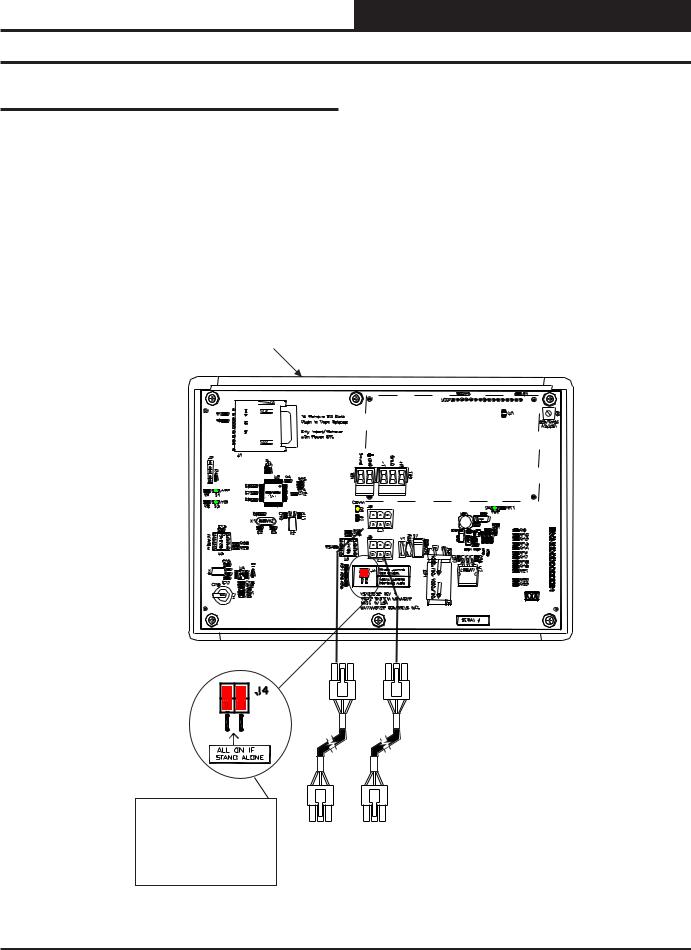
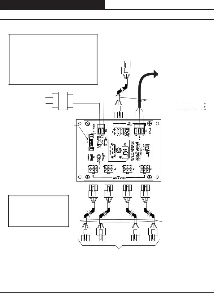
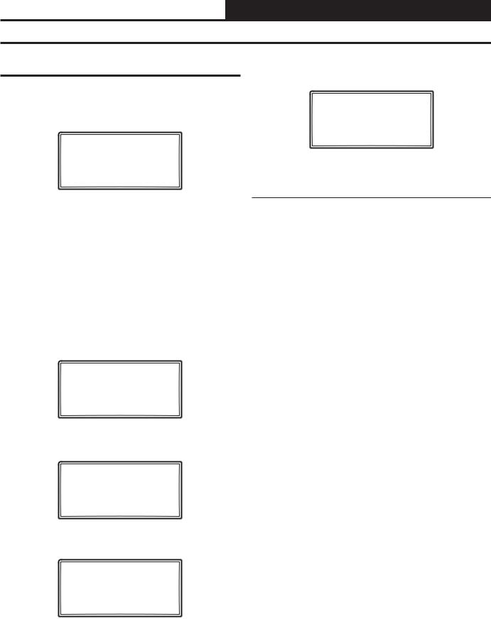
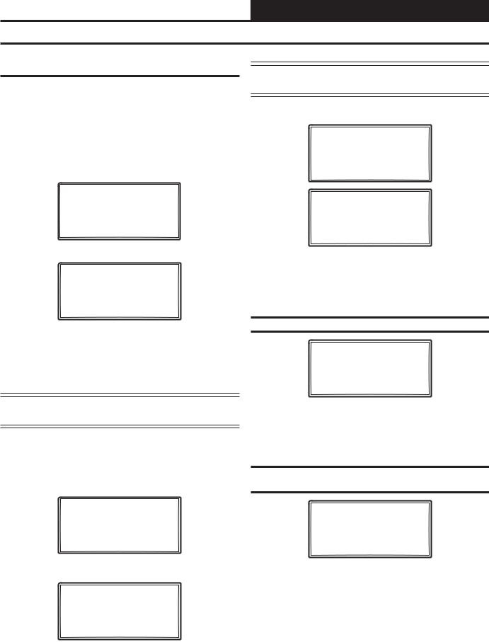
As previously described, when you are connecting the Modular System Manager to a Networked System, the Modular System Manager is connected to the communications and power loop of the system via modular cables. These cables simply plug into the System Manager board and to any device with modular connectors on any local loop on the system. Devices with modular connectors include the Power/Comm Distribution Board, VAV/Zone controller, and MiniLink Polling Device. By using these plug-in connections, wiring errors are virtually eliminated and system installation is fast and easy. See Figure 4 below for typical connection information. See Figure 5 on page 8 for typical Power/Comm board wiring and connection information.
When the System Manager is to be connected to a Stand Alone system, a 12-foot cable with modular connectors on one end and stripped wire ends on the other end is provided for this purpose. This is used to facilitate connecting communications and power wiring to the Modular System Manager from a 24 VAC power source and to the HVAC unit controller communication wiring terminals. See Figure 6 on page 9 for wiring details. If the supplied cable wire is not long enough for your installation, a standard modular cable of the correct length can be purchased through WattMaster and one of the modular connectors can be cut off to allow for the transformer and communication terminal wiring connections. It is recommended that you do not splice the communications wire if at all possible. The transformer should be rated at 6 VA minimum power output.
Modular System Manager SD
Back View
4GB
All Modular Power/Comm
Cables Are To Be
WattMaster Part Number
PCC-xx Or PCCE-xx
Cables.
NOTE: For Stand-Alone Installations (No CommLink or MiniLink), All TERM Jumpers Must Be ON.
For All Applications With CommLink(s) Or MiniLink(s), All Jumpers Must Be OFF.
Power/Comm Cables To
Power/Comm Distribution
Board, MiniLink Polling Device
Or VAV/Zone Controllers On
Local Loop.
Figure 4: Modular System Manager SD - Network
VCC-X Operator Interface SD |
7 |
SYSTEM CONNECTION
Power/Comm Board Wiring
WARNING!
DO NOT GROUND THE 24V TRANSFORMER THAT IS TO BE USED WITH THE POWER/COMM BOARDS. GROUNDING OF THE TRANSFORMER WILL DAMAGE THE POWER/COMM BOARD AND ALL BOARDS CONNECTED TO IT. A SEPARATE TRANSFORMER MUST BE USED FOR EACH POWER/COMM BOARD. NO EXCEPTIONS. DO NOT CONNECT ANY OTHER DEVICES TO THE TRANSFORMER USED FOR THE POWER/COMM BOARD!
A Power/Comm Cable Can Be Used To
Connect With The MiniLink PD Instead Of
Using 2 Conductor Twisted Pair With Shield
Cable. You Can Also Use A Power/Comm
Cable To Connect With Another Power/Comm
Board, A System Manager Or A VAV/Zone
Controller.
If Desired, Instead Of Using A
Power/Comm Cable, You Can Use 2
Conductor Twisted Pair With Shield
Cable To Connect To The Power/
Comm Board From The Unit
Controller, MiniLink PD, Or Another
Power/Comm Board.
Line Voltage |
|
Local Loop RS-485 |
All Comm Loop Wiring Is |
|||
|
|
Straight Thru |
|
|||
|
24VAC |
9600 Baud |
T |
T |
T |
T |
|
|
|||||
|
|
SH |
SH |
SH |
SH |
|
|
|
|
||||
|
|
|
R |
R |
R |
R |
24VAC Transformer (By Others)
4 Amp Slow Blow Fuse |
|
C |
|
US |
R |
NOTE: |
|
Diagram Shown Is For Wiring Of |
|
Power/Comm Board When Used |
|
For Connecting Local Loop Devices |
|
Such As VAV/Zone Controllers, |
|
System Manager(s) and Other |
|
Power/Comm Boards. |
Local Loop RS-485 |
|
9600 Baud |
Power/Comm Cable To Other Power/Comm Board(s),
System Manager, Or VAV/Zone Controllers On Local Loop Only.
Figure 5: Typical Power/Comm Board Wiring
8 |
VCC-X Operator Interface SD |
SYSTEM CONNECTION
Stand Alone Connection
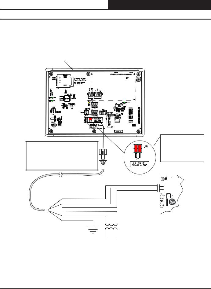
Modular System Manager SD
Back View
4GB
NOTE: If Desired A Power/Comm Board As Used With The Networked System Can Be Installed And Wired Instead Of Using The Pigtail Cable Wiring Shown Below. See The Networked System Wiring Diagram For Details.
Use Supplied Modular Cable
With Stripped Ends For
Connection To Terminal Block
And Transformer
WHITE (T)
DRAIN WIRE (SHLD)
BLACK (R)

 RED (24 VAC)
BROWN (GND)
GREEN (GND)
NOTE: For Stand-Alone Installations (No CommLink or MiniLink), All TERM Jumpers Must Be ON.
For All Applications With CommLink(s) Or MiniLink(s), All Jumpers Must Be OFF.


 T
T


 SHLD
SHLD


 R
R
Controller Board
Class 2 Transformer
Rated For 6 VA Minimum
Figure 6: Modular System Manager SD - Stand Alone
VCC-X Operator Interface SD |
9 |

MODULAR SERVICE TOOL SD
Modular Service Tool Keys
Operator Interfaces
In order to configure and program the VCC-X Controller, you must have an Operator’s Interface or a personal computer with the Prism 2 computer front-end software installed. Two different Operator Interfaces are available for programming of the VCC-X Controls System—the Modular Service Tool SD and/or the System Manager TS. These devices allow you to access the status and setpoints of any controller on your communications loop. This manual describes the Modular Service Tool SD. If using the System Manager TS II, please see the System Manager TS II Technical Guide. If using Prism 2, please see the Prism 2 Technical Guide.
The Modular Service Tool allows you to view any input or output status and change any setpoint to fine-tune the operations of the total system. All keypad operations are simple and straightforward, utilizing non-cryptic plain English messages.
Display Screens & Data Entry Keys
See the chart below for a list of the keypad descriptions and functions.
Keypad |
Function |
Description |
|
ESC |
Use this key to exit from screens or |
|
from data entry or to return to the |
|
Main Screen from any screen in the |
|
system. |
ENTER |
Use this key to enter a new value. |
Clear |
If a data entry mistake is made, |
|
press this key to clear the data entry |
|
field and start over. This key also |
|
turns off the power to the Service |
|
Tool when on the |
|
Main Screen |
Minus |
If a setpoint with a negative value |
|
is required, press this key for the |
|
minus sign. |
DEC |
Press this key when entering data |
|
that requires a decimal point. |
|
Use these keys to change values |
|
in the Configuration Screens as |
|
prompted. |
|
Use these keys to step backward or |
|
forward through the screens. |
|
|
|
|
Mode Selection Buttons
The Modular Service Tool is provided with “Mode Selection Buttons.” These buttons give you instant access to the specific mode desired without having to scroll through several menu screens to get there.
Button |
Function |
Description |
|
STATUS |
Pressing this button takes you |
|
directly to the controller |
|
“Status” screens. |
SETPOINTS |
Pressing this button takes you |
|
directly to the controller |
|
“Setpoints” screens. |
SCHEDULES |
Pressing this button takes you |
|
directly to the controller |
|
“Schedules” screens. |
OVERRIDES |
Pressing this button takes you |
|
directly to the controller “Over- |
|
rides” screen. See the “Override |
|
Button” section on page 21 for a |
|
description of this function. |
|
See Note 1 below. |
ALARMS |
Pressing this button takes you |
|
directly to the controller |
|
“Alarms” screen. See the “Alarms |
|
Button” section on page 20 for a |
|
description of this function. |
CONFIGURATION |
Pressing this button takes you |
|
directly to the controller |
|
“Configuration” screens. |
BALANCE-TEST |
Pressing this button takes you |
|
directly to the controller |
|
“Balance-Test” screens. |
|
|
NOTE:
(1) The Modular Service Tool will only search the Overrides one loop at a time. You must enter the Loop number and the MiniLink PD unit ID (60).
Table 2: Button Descriptions
Table 1: Keypad Descriptions
10 |
VCC-X Operator Interface SD |
MODULAR SERVICE TOOL SD
Initialization & Setting the Time & Date
Modular Service Tool Initialization
Modular Service Tool Initialization Screen and Setup Screens
After connecting the Service Tool to the controller with the supplied cable, press <ON>. The Initialization Screen will appear followed by the Setup Screens as shown below. If there is no SD card installed, the second screen will display, “No SD Card Connected! Powering Down!”
Although the times are displayed on the Main Screen in a standard 12-hour format, you must program them using the 24-hour military format. If you configured the VCC-X Controller to use its own Internal Schedules, the Occupied/Unoccupied modes are calculated on the basis of the current real time clock reading.
The two screens that follow will appear. To scroll through the fields, press <> or <ENTER>. In order to save a new value, you must press <ENTER>.
Initializing
Service Tool vX.XX
WattMaster Controls
1)Set Time & Date
2)Communications NEXT) More Options
ESC) Exit Menu
3)Energy Saving
4)Update Software NEXT) More Options
ESC) Exit Menu
Program Time/Date |
||
Day |
(Sunday=0): X |
|
Enter Hr. (0-23): XX |
||
Enter Minutes |
: XX |
|
Day - |
Enter the Day of the Week (0 to 6) |
|
Sunday = 0 |
Hours (Hr) - Enter Hours in 24-Hour Military Format (1700 = 5:00 PM)
Minutes - Enter the Minutes
(0 to 59)
Programming the Date
NOTE: Once you press <ESC> while at the Setup Screens shown above, you can access them again by pressing <NEXT> or cycling power.
Setting The Time & Date
The Modular Service Tool is equipped with a real time clock chip allowing it to maintain the correct time. Once you have programmed the correct time and date, the information is broadcast globally to all controllers on the entire system.
NOTE: If you are in a time zone that has daylight savings, you will need to manually adjust the time twice a year.
To scroll through the fields, press <> or <ENTER>. In order to save a new value, you must press <ENTER>.
Program Time/Date |
||
Month |
(1-12): |
XX |
Day |
(1-31): |
XX |
Year |
(00-99): |
XX |
Month |
- |
Enter the Month (1 to 12) |
Day |
- |
Enter the Day of the Month (1 to 31) |
Year |
- |
Enter the current Year with two digits |
|
|
(00 to 99) |
Programming the Time
From the Setup Screen shown below, press <1> on your keypad to access the Set Time & Date Screens. (You may have to press <NEXT> to access this screen).
1)Set Time & Date
2)Communications NEXT) More Options
ESC) Exit Menu
When you have finished programming the time and date, press <ESC> to return to the Setup Screen shown below.
1)Set Time & Date
2)Communications NEXT) More Options
ESC) Exit Menu
VCC-X Operator Interface SD |
11 |
MODULAR SERVICE TOOL SD
Setting the Operating Mode and Energy Saving Timer
Setting the Operating Mode
The Operating Mode is displayed on the last line of the Main Screen as shown below. The factory default setting for the Service Tool is
LS (Low Speed) Stand Alone Mode. LS Stand Alone Mode is the correct configuration for the VCC-X Controller when in Stand Alone Mode.
Service Tool SD vX.XX
Wednesday Operations
01/16/15 02:21 PM
LS Stand Alone *00*
If you are using this Service Tool on a communications loop and have an installed MiniLink PD or CommLink, you will need to change the setting to LS (Low Speed) Network Mode.
If you are using a VCC-X Controller that is set for high speed, you will need to change the setting to HS (High Speed) Stand Alone Mode or HS (High Speed) Network Mode.
If your display indicates a different mode than the one you need, press <2> at the Setup Screen shown below. You may have to press <NEXT> to access this screen.
1)Set Time & Date
2)Communications NEXT) More Options
ESC) Exit Menu
The Communications Screen will appear as shown below.
Stand Alone Mode
Lo Speed Connection
Use Left/Right Arrow
To Change Selections
Press <> or <> to select the proper mode of operation.
When you have made your selection, press <ENTER>. The following screen will appear.
You Have Changed The
System Mode
Press Any Key To
Continue
Press any key to continue. The Setup Screen will appear as shown below:
1)Set Time & Date
2)Communications NEXT) More Options
ESC) Exit Menu
Setting the Energy Saving Timer
The Modular Service Tool has a built-in timer that can be programmed to shut the Service Tool off after a specified period of time if no buttons are pressed. This is a very useful feature if you are powering the Service Tool from the internal batteries.
To set the Energy Saving Timer, press <NEXT> at the first Setup Screen and <3> at the second Setup Screen shown below. (You may have to press <NEXT> to access these screens).
1)Set Time & Date
2)Communications NEXT) More Options
ESC) Exit Menu
3)Energy Saving
4)Update Software NEXT) More Options
ESC) Exit Menu
The Energy Saving Screen will appear as shown below:
Energy Saving
Automatic Power Down
Minutes: xx
Press ESC to Exit
Enter the number of minutes you want the Service Tool to stay active before it automatically powers down and press <ENTER>. To cancel the automatic power down, enter <99> and press <ENTER>. After you have entered a number between 1 and 99 minutes, press <ESC> to exit the screen.
The Setup Screen will appear again as shown below:
1)Set Time & Date
2)Communications NEXT) More Options
ESC) Exit Menu
12 |
VCC-X Operator Interface SD |

MODULAR SERVICE TOOL SD
Alarm and Override Search
Modular Service Tool Alarm Search
NOTE: When you press the <ALARMS> button on the Modular Service Tool, it will search only the unit ID that you have entered; therefore, you must search each unit individually to access all alarms for that controller.
To search for alarms, press <ALARMS> while on any screen but the
Main Screen. The Unit Selection Screen will be displayed.
Enter Unit Address
Then Press Enter
Selected Unit #_1
Press Down
Enter the Unit ID of the controller the Service Tool is connected to and press <ENTER>. Once communication is established, the *00* message will go away. Then press <>.
NOTE: If the *00* remains, it indicates a communication failure to the controller.
One of the following screens will appear:
VCC-X V.XXX
NO ALARMS
VCC-X V.XXX
ALARMS PRESENT
SCROLL DOWN TO VIEW
Press <> to scroll through all the alarms for the controller that the Modular Service Tool is connected to.
To clear any alarms that are found, you must fix the problem indicated in the alarm. Once the problem is fixed, the alarm will clear from the screen the next time the unit is polled.
Modular Service Tool Override Search
When a space sensor with override option is used with any VAV/ Zone or Unit Controller, the Modular Service Tool can determine and report any controllers that are currently operating in an override condition on a specific Loop by entering a Loop ID number and then doing a search.
NOTE: When you press the <OVERRIDES> button on the Modular Service Tool, it will search only the Loop number that you enter; therefore, you must search each loop individually to access all overrides.
To access the Overrides Screen, press <OVERRIDES> from the Modular Service Tool’s keypad. A screen will appear asking you to enter the unit ID.
Enter Unit Address
Then Press Enter
Selected Unit #160
Press Down
Enter the Unit ID for the MiniLink PD (MLPD) of the loop you wish to search and press <ENTER>. The MLPD is always address 60 on each loop. So the unit ID of any particular MLPD would be the loop number followed by 60. In the example above, Loop 1, address 60 has been entered. Once communication is established, the *00* message will go away. Then press <>.
NOTE: If the *00* remains, it indicates a communication failure to the controller.
If communications are successful, one of the following screens will appear:
VCC-X V.XXX
NO OVERRIDES
VCC-X V.XXX
OVERRIDES PRESENT
SCROLL DOWN TO VIEW
After the Service Tool completes its search, it will post a message to tell you if there are overrides present. If there are overrides, press <> and all units on the loop will be listed showing ‘Override: Yes or No.’Press <OVERRIDES> again to access overrides on a different loop. Enter the Unit ID of the MLPD of that loop.
VCC-X Operator Interface SD |
13 |
MODULAR SERVICE TOOL SD
Schedules and Holidays
Scheduling
You can access the Unit Controller Scheduling Screens by pressing <SCHEDULES>. The Unit Selection Screen will be displayed.
Enter Unit Address
Then Press Enter
Selected Unit #_1
Press Down
Enter the Unit ID of the controller the Service Tool is connected to and press <ENTER>. Once communication is established, the *00* message will go away. Then press <>.
NOTE: If the *00* remains, it indicates a communication failure to the controller.
Press the <> button and then press <ENTER> to access the scheduling function you wish to view.
VCC-X Schedule Menu
Schedule Override
Week Schedules
Holidays
Week Schedules
Event #1
VCC-X Schd |
ID # |
|
Sunday |
Event #1 |
|
Start |
Time: XXXX |
|
Stop |
Time: XXXX |
|
|
Event #2 |
|
VCC-X Schd |
ID # |
|
Sunday |
Event #2 |
|
Start |
Time: XXXX |
|
Stop |
Time: XXXX |
|
If you are using the internal scheduling capability of the Unit Controller, set the schedule hours and holiday periods from the menu shown above. You can also force the unit to operate continuously in occupied or unoccupied mode by selecting the Schedule Override menu item and entering the desired command.
If you are using an external contact closure to signal the occupied mode, you must access the Week Schedule Screens and set all start and stop times to zero to prevent the internal schedule from turning the equipment on when you don’t want it to operate.
The screens will step through the Start Time and then the Stop Time for each day of the week. You can quit at any point in the process by pressing <ESC>. There are two Start/Stop events available per day, so the screen will show which event is being programmed. If you need only one event, keep Event #2’s times set at ZERO.
All times are in 24-hour military format, so 5:00 PM would be entered as 1700.
If both the Start and Stop Times are ZERO, the schedule is in a continuous OFF mode. (Also, use for Remote Forced Occupied applications using the Forced Occupied Binary Input.)
If both the Start and Stop Times are 2359, the schedule is in a continuous ON mode.
NOTE: The second line displays which day of the week is currently being programmed. The day of the week automatically increments as you exit the Event #2 screen for the day and continue to the next day’s Event #1 screen.
CAUTION: The controller ships with all schedules set to zerosothatthecontrollerwillnotattempttoheat or cool before you have configured the system.
Holiday Start/Stop Day Selection
VCC-X Schd |
ID # |
Holiday # |
1 |
Start Mon/Day: XXXX |
|
[ July 4th = 704 ] |
|
VCC-X Schd |
ID # |
Holiday # |
1 |
Stop Mon/Day: XXXX
[ July 5th = 705 ]
The screens will step through the fourteen possible holidays, one period at a time. Line 2 shows which holiday is currently being programmed. Since a holiday period can encompass more than one day, you need to program the day the holiday starts and the day the holiday ends. If your holiday only lasts one day, simply set both the Start Day and the Stop Day to the same value. Remember to combine the month and day into a single four-digit value.
EXAMPLE: 704 = July 4th (NOTE: Leading zero not required)
1225 = December 25th
14 |
VCC-X Operator Interface SD |
MODULAR SERVICE TOOL SD
Holiday Scheduling and Schedule Override
Holiday Start/Stop Times |
|
|
Schedule Override |
|
|
VCC-X Schd |
ID # |
|
VCC-X Ovrd |
ID # |
|
Holiday Schedule |
|
Schedule Override |
|||
Start |
Event #1: XXXX |
|
Enter Override: X |
||
Stop |
Event #1: XXXX |
|
[0=Auto 1=ON |
2=OFF] |
|
VCC-X Schd |
ID # |
|
Holiday Schedule |
||
Start |
Event #2: XXXX |
|
Stop |
Event #2: XXXX |
|
The fourteen holidays all use the same Start and Stop times which you program on this screen and the next. You must enter the time in 24-hour military format, the same as a regular week schedule.
Normally, the holidays will operate in an unoccupied mode or a reduced schedule mode. There are two start/stop events available on holidays to match the standard schedule number of events.
If you want to force the unit to operate in a continuous Occupied or Unoccupied mode, select this menu item to activate the desired method. If a Schedule Override is active, all other methods of schedule control are ignored (Push-Button, Internal, and Remote).
As you can see on the last line of the display, enter <1> to run continuously in the Occupied Mode or <2> to run continuously in the Unoccupied Mode. To restore normal schedule operations, enter <0>.
This override remains in effect until canceled and does not time-out like the Output Overrides do after 10 minutes of no communications.
NOTE: Do not use the Force OFF mode in place of setting all the week schedules to ZERO if you are using a Remote Signal for your scheduling since the Override has priority over the Remote Signal.
VCC-X Operator Interface SD |
15 |

MODULAR SYSTEM MANAGER SD
System Manager SD Keys and Buttons
Operator Interfaces
In order to configure and program the Orion System controllers, you must have an Operator’s Interface or a personal computer with the Prism 2 computer front-end software installed. Three different Operator Interfaces are available for programming of the Orion Controls System—the Modular Service Tool SD, the Modular System Manager SD, and/or the System Manager TS II. These devices allow you to access the status and setpoints of the controllers on your communications loop. This manual describes the Modular System Manager SD. If using the System Manager TS II, please see the
System Manager TS II Technical Guide. If using Prism 2, please see the Prism 2 Technical Guide.
The Modular System Manager SD allows you to view any input or output status and change any setpoint to fine-tune the operations of the total system. All keypad operations are simple and straightforward, utilizing non-cryptic plain English messages.
Display Screens & Data Entry Keys
See the chart below for a list of the keypad descriptions and functions.
Keypad |
Function |
Description |
|
ESC |
Use this key to exit from screens or from data |
|
entry or to return to the Main Screen from |
|
any screen in the system. |
ENTER |
Use this key to enter a new value. |
Clear |
If a data entry mistake is made, press this key |
|
to clear the data entry field and start over. |
Minus |
If a setpoint with a negative value is required, |
|
press this key for the minus sign. |
DEC |
Press this key when entering data that re- |
|
quires a decimal point. |
|
Use these keys to change values in the Con- |
|
figuration Screens as prompted. |
|
Use these keys to step backward or forward |
|
through the screens. |
|
|
|
|
Mode Selection Buttons
The Modular System Manager is provided with “Mode Selection Buttons.” These buttons give you instant access to the specific mode desired without having to scroll through several menu screens to get there.
Button |
|
Description |
Function |
|
|
STATUS |
Pressing this button takes you directly to |
|
the controller “Status” screens. |
SETPOINTS |
Pressing this button takes you directly to |
|
the controller “Setpoints” screens and |
|
“Configuration” menu. |
SCHEDULES |
Pressing this button takes you directly to |
|
the controller “Schedules” screens. |
OVERRIDES |
Pressing this button takes you directly to |
|
the controller “Overrides” screen. See the |
|
“Override Button” section on page 21 for a |
|
description of this function. |
|
See Notes 1 & 2 below. |
ALARMS |
Pressing this button takes you directly to |
|
the controller “Alarms” screen. See the |
|
“Alarms Button” section on page 20 for a |
|
description of this function. |
|
See Notes 1 & 2 below. |
NOTES: |
|
(1)This button only functions when the system is configured for “Network Mode” or “Multiple MGRS Mode.” It will not function in “Stand Alone Mode.”
(2)The “Search for Units” function must be performed on the System Manager upon initial system setup before this function will be available. See the “Network Mode & Multiple Managers Loop Search” on page 20 of this manual for complete instructions on performing a loop search.
Table 4: Button Descriptions
Table 3: Keypad Descriptions
16 |
VCC-X Operator Interface SD |
MODULAR SYSTEM MANAGER SD
Initialization & Setting the Time & Date
System Manager SD Initialization
System Manager SD Initialization Screen and Setup Screens
After connecting the System Manager to the controller with the supplied cable, press <ON>. The Initialization Screen will appear followed by the Setup Screens as shown below. If there is no SD card installed, the second screen will display, “No SD Card Connected! Powering Down!”
NOTE: After exiting these screens, you can access them again by pressing <ESC> and then <> or by cycling power.
INITIALIZING
System Manager SD
vX.XX
WattMaster Controls
1)Set Time & Date
2)Communications NEXT) More Options
ESC) Exit Menu
3)Change Passcodes
4)Loop Search NEXT) More Options
ESC) Exit Menu
5) Alarm Search
NEXT) More Options
ESC) Exit Menu
Programming the Time
From the Setup Screen shown below, press <1> on your keypad to access the Set Time & Date Screens.
1)Set Time & Date
2)Communications NEXT) More Options
ESC) Exit Menu
Although the times are displayed on the Main Screen in a standard 12-hour format, you must program them using the 24-hour military format. If you configured the Unit Controller to use its own Internal Schedules, the Occupied/Unoccupied modes are calculated on the basis of the current real time clock reading.
The two screens that follow will appear. To scroll through the fields, press <> or <ENTER>. In order to save a new value, you must press <ENTER>.
Program Time/Date |
||
Day |
(Sunday=0): X |
|
Enter Hr. (0-23): XX |
||
Enter Minutes |
: XX |
|
Day - Enter the Day of the Week (0 to 6)
Sunday = 0
Hours (Hr) - Enter the Hour (0-23) in
24-Hour Military Format
(13 = 1:00 PM)
Minutes - Enter the Minutes
(0 to 59)
Programming the Date
To scroll through the fields, press <> or <ENTER>. In order to save a new value, you must press <ENTER>.
Setting The Time & Date
The System Manager SD is equipped with a real time clock chip allowing it to maintain the correct time. Once you have programmed the correct time and date, the information is broadcast globally to all controllers on the entire system.
NOTE: A Level 1 or Level 2 User can set the time and date.
NOTE: If you are in a time zone that has daylight savings, you will need to manually adjust the time twice a year.
Program Time/Date
Month |
(1-12): |
XX |
Day |
(1-31): |
XX |
Year |
(0-99): |
XX |
Month - Enter the Month (1 to 12)
Day - Enter the Day of the Month (1 to 31)
Year - Enter the current Year (0 to 99)
When you have finished programming the time and date, press <ESC> to return to the Setup Screen.
VCC-X Operator Interface SD |
17 |
MODULAR SYSTEM MANAGER SD
Setting the Operating Mode
Setting the Operating Mode
The Operating Mode is displayed on the last line of the Main Screen as shown below. The factory default setting for the System Manager is LS (Low Speed) Stand Alone Mode.
System Manager SD
Wednesday Operations
01/16/15 02:21 PM
LS Stand Alone Mode
The System Manager must be configured for the correct mode of operation for your system. There are 5 modes of operation available for the Orion System—LS (Low Speed) Stand-Alone, HS (High
Speed) Stand-Alone, LS (Low Speed) Network, HS (High Speed) Network, and LS (Low Speed) & HS (High Speed) Multiple MGRS.
If you are using this System Manager on a communications loop that doesn’t have a MiniLink PD or CommLink connected to it and you have a single System Manager on your system, then you need to operate in LS (Low Speed) Stand-Alone Mode. If you are using a VCC-X Controller or GPC-XP Controller that is set for high speed, and you don’t have a MiniLink PD or CommLink connected to the loop, then you will need to change the setting to HS (High Speed) Stand Alone Mode.
If you are using the System Manager on a communications loop and have an installed MiniLink PD or CommLink, you will need to change the setting to LS (Low Speed) Network Mode. If you are using a VCC-X Controller or GPC-XP Controller that is set for high speed, and are using a MiniLink PD or CommLink, then you will need to change the setting to HS (High Speed) Network Mode.
If you are using this System Manager on a communications loop, have a MiniLink PD or CommLink installed, and have multiple System Managers, then you need to operate in Multiple MGRS Mode.
If your display indicates a different mode than the one you need, press <2> at the Setup Screen shown below. You will have to cycle power to get to this screen or by pressing <ESC> and <PREV>.
1)Set Time & Date
2)Communications NEXT) More Options
ESC) Exit Menu
The Passcode Clearance Screen will appear as shown below.
THIS ACTION REQUIRES
A SPECIAL HIGH LEVEL
PASSCODE CLEARANCE
Enter: XXXXXXX
Enter the seven digit passcode <2337377> to access the next screen.
You will then see the screen below displayed.
Stand Alone Mode
Lo Speed Connection
Use Left/Right Arrow
To Change Selections
Press <> or <> if you need to change the mode of operation to LS (Low Speed) Stand-Alone, HS (High Speed StandAlone, LS (Low Speed) Network, HS (High Speed Network,
LS (Low Speed) Multiple Manager or HS (High Speed) Multiple Manager and then press <ENTER> to save your selection. If you are not using Multiple Manager Mode, press <ESC> at the screen below and continue scrolling right and left.
Multiple Manager
Unit Address: 0
Press ESC to Exit
For Multiple MGRS Mode, enter the address at which you want this particular System Manager to be set.
When multiple System Managers are used on a local loop, each must be set with a unique address different from any other device on that loop. You must perform this same operation again for each System Manager installed. If you want one of these System Managers to be able to indicate alarms and overrides for the entire system, you must select either LS or HS Network Mode on that particular System Manager.
Once you have the correct number per the display above displayed, press <ENTER>. The following screen will appear telling you that you have changed the system mode:
You Have Changed The
System Manager Mode
Press Any Key To
Continue
Press any key on the keyboard to exit this screen.
18 |
VCC-X Operator Interface SD |
MODULAR SYSTEM MANAGER SD
Changing Passcodes
System Manager Passcodes
Changing the mode of operation, updating software, changing schedules, and changing setpoints and configurations require passcode clearance. The screen below will appear if this action requires passcode clearance.
THIS ACTION REQUIRES
PASSCODE CLEARANCE
Enter Passcode: XXXX
Passcodes can only be changed by a Level 2 user. Enter the passcode and press <ENTER>. The following screen will appear:
Enter New Passcode
Level 1.....: XXXX
Level 2.....: XXXX
[Must Be 4 Digits]
This screen allows you to enter new Level 1 and/or Level 2 passcodes. Passcodes must always be four digits in length, so the usable range of numbers is 1000 to 9999.
The System Manager has three levels of user access. All users can |
CAUTION: If you change the Level 2 passcode and can- |
view Status Screens. Level 1 users are limited to changing the Time |
not remember what it is, you will be locked |
and Date and Operating Schedules. Level 2 users have complete |
out of your system! |
system access. Any status or setpoint field can be read or reset from |
|
|
|
|
|
the System Manager. |
|
These two levels of passcodes are programmable by any Level 2 |
|
user. The default Level 1 passcode is “1111” and the default Level |
|
2 passcode is “2222.” |
|
If you wish to change either Level 1 or Level 2 passcodes, please |
|
see the instructions that follow. |
|
From the Main Status Screen, press <ESC> and then press <PREV>. |
|
The following screen will appear: |
|
1)Set Time & Date
2)Communications NEXT) More Options ESC) Exit Menu
Press <> for the Next Menu. The following screen will be displayed:
3)Change Passcodes
4)Loop Search NEXT) More Options ESC) Exit Menu
Press <3> for Change Passcodes. The following screen will be displayed:
THIS ACTION REQUIRES
PASSCODE CLEARANCE
Enter Passcode: XXXX
VCC-X Operator Interface SD |
19 |
MODULAR SYSTEM MANAGER SD
Loop Search and System Alarm Search
Network Mode & Multiple Managers
Loop Search
When the System Manager is configured for Network Mode, a loop search must initially be performed for the System Manager to recognize alarms or overrides. Also, when you have a system that has multiple System Managers and you have one of the System Managers set to (63) Network Mode for alarm and override indication, you must also perform a loop search for that System Manager. This allows the System Manager to be aware of all alarms and overrides for all local loops on the entire system.
To access the Loop Search Screen, from the Setup Screen, press <ESC> and then press <PREV>.
1)Set Time & Date
2)Communications NEXT) More Options
ESC) Exit Menu
Press <> for Next Menu. The following screen will be displayed:
3)Change Passcodes
4)Loop Search NEXT) More Options
ESC) Exit Menu
Press <4> for Loop Search. The following screen will be displayed:
Loop Search
Current Loop = XX
Loops Found = XX
Searching
The System Manager will now proceed to search all loops to find the MiniLink PDs that are connected to the system. The screen will display the current loop being searched and the number of loops currently found.
Once the search is completed, the following screen will be displayed:
Loop Search
Finished
Loops Found = XX
Press ESC to Exit
The screen will display the number of loops found on your system. The information will be saved into the System Manager’s memory. No further loop searches will be required unless you add an additional MiniLink PD to the Network System.
System Alarm Search
The System Manager can be used to search for all active alarms on the system. You must configure the MiniLink PD to allow for “Alarm Polling” for each controller you want polled for alarms. See the MiniLink PD programming section on page 79 of this manual for setting information.
This option will alert you of the number of alarms present on individual units, but will not tell you what type of alarm are present. You will have to perform and individual unit alarm search for detailed alarm information.
To access the Alarm Search Screen, from the Setup Screen, press
<ESC> and then press <PREV>.
.
1)Set Time & Date
2)Communications NEXT) More Options
ESC) Exit Menu
Press <> for Next Menu. The following screen will be displayed:
3)Change Passcodes
4)Loop Search NEXT) More Options
ESC) Exit Menu
Press <> for Next Menu. The following screen will be displayed:
5) Alarm Search
NEXT) More Options
ESC) Exit Menu
Press <5> for Alarm Search. The entire system is searched from this point. The following screen will be displayed:
Alarm Screen
SEARCHING!
Once the Alarm Search is complete, one of the following screens will display:
Alarm Screen
XX ALARMS ON UNIT XX
20 |
VCC-X Operator Interface SD |
MODULAR SYSTEM MANAGER SD
Unit Alarm Search and Override Search
Alarm Screen
NO ALARMS DETECTED
To check controllers individually for alarms, use the <ALARMS> button on the Main Display.
Unit Alarm Search
The System Manager can be used to search for all active alarms one controller at a time.
Press <ALARMS>. The Unit Selection Screen below will be displayed.
Enter Unit Address
Then Press Enter
Selected Unit #_1
Press Down
Enter the Unit ID of the controller you wish to search and press <ENTER>. Once communication is established, the *00* message will go away. Then press <>.
NOTE: If the *00* remains, it indicates a communication failure to the controller.
The following screen will appear. The System Manager will search for any active alarms on the unit and one of the following screens will appear:
CONTROLLER V.XXX
NO ALARMS
CONTROLLER V.XXX
ALARMS PRESENT
SCROLL DOWN TO VIEW
System Manager Override Search
NOTE: In order for the Override Search to work, a Loop Search must be performed first. See page 20 for details.
When a space sensor with override option is used with any VAV/Zone Controller or Unit Controller, the System Manager can determine and report any controllers that are currently operating in an override condition. This function requires that a MiniLink PD is installed on each loop where the controllers may be located. The MiniLink PD must be configured to allow for “Alarm Polling” for each controller that Override Polling Enabled is desired for this function to work. See the MiniLink PD programming section on page 79 of this manual for setting information.
To access the Space Sensor Overrides Screen, press <OVERRIDES>, The following screen will appear.
Overrides Screen
SEARCHING!
After the System Manager completes its search, it will list the first unit on the system that is currently in the override mode. Press the <> button to scroll through all units that are in the Override Mode.
Overrides Screen
Loop = 1 Unit = 59
OVERRIDE FOUND
Press <> to scroll through all the alarms for the controller that the Modular Service Tool is connected to.
To clear any alarms that are found, you must fix the problem indicated in the alarm. Once the problem is fixed, the alarm will clear from the screen the next time the unit is polled.
VCC-X Operator Interface SD |
21 |
MODULAR SYSTEM MANAGER SD
Schedules and Holidays
Scheduling
You can access the Controller Scheduling Screens by pressing
<SCHEDULES>. The screen below will appear because Scheduling requires passcode clearance. A Level 1 or 2 passcode can change schedules.
THIS ACTION REQUIRES
PASSCODE CLEARANCE
Enter Passcode: XXXX
If the correct passcode was entered, the Unit Selection Screen will be displayed.
Enter Unit Address
Then Press Enter
Selected Unit #_1
Press Down
Enter the Unit ID of the controller you wish to change schedules for and press <ENTER>. Once communication is established, the *00* message will go away. Then press <>.
NOTE: If the *00* remains, it indicates a communication failure to the controller.
The Unit Schedule Menu will be displayed.
Schedule Menu
Schedule Override
Week Schedules
Holiday Schedules
Press the <> button until the cursor is on the desired option and then press <ENTER>.
Week Schedules
From the Unit Schedule Menu, select Week Schedules. The following two screens will appear in order:
Event #1
Schd
Sunday Event #1
Start Time..: XXXX
Stop Time...: XXXX
Event #2
Schd
Sunday Event #2
Start Time..: XXXX
Stop Time...: XXXX
If you are using the internal scheduling capability of the Controller, set the schedule hours and holiday periods from the menu shown above. You can also force the unit to operate continuously in occupied or unoccupied mode by selecting the Schedule Override menu item and entering the desired command.
If you are using an external contact closure to signal the occupied mode, you must access the Week Schedule Screens and set all start and stop times to zero to prevent the internal schedule from turning the equipment on when you don’t want it to operate.
The screens will step through the Start Time and then the Stop Time for each day of the week. You can quit at any point in the process by pressing <ESC>. There are two Start/Stop events available per day, so the screen will show which event is being programmed. If you need only one event, keep Event #2’s times set at ZERO.
All times are in 24-hour military format, so 5:00 PM would be entered as 1700.
If both the Start and Stop Times are ZERO, the schedule is in a continuous OFF mode. (Use for Remote Signal Contact.)
If both the Start and Stop Times are 2359, the schedule is in a continuous ON mode.
NOTE: The second line displays which day of the week is currently being programmed. The day of the week automatically increments as you exit the Event #2 screen for the day and continue to the next day’s Event #1 screen.
CAUTION: The controller ships with all schedules set to zero so that the controller will not attempt to heat or cool before you have configured the system.
22 |
VCC-X Operator Interface SD |
MODULAR SYSTEM MANAGER SD
Holiday Scheduling and Schedule Override
Holiday Start/Stop Day Selection
From the Unit Schedule Menu, select Holiday Schedules. The following four screens will appear in order:
Hldy
Holiday # 1
Start Mon/Day.: XXXX
[ July 4th = 704 ]
Hldy
Holiday # 1
Stop Mon/Day.: XXXX
[ July 5th = 705 ]
The screens will step through the fourteen possible holidays, one period at a time. Line 2 shows which holiday is currently being programmed. Since a holiday period can encompass more than one day, you need to program the day the holiday starts and the day the holiday ends. If your holiday only lasts one day, simply set both the Start Day and the Stop Day to the same value. Remember to combine the month and day into a single four-digit value.
EXAMPLE: 704 = July 4th (NOTE: Leading zero not required)
1225 = December 25th
Holiday Start/Stop Times
Hldy
Holiday Schedule
Start Event #1: XXXX
Stop Event #1: XXXX
Hldy
Holiday Schedule
Start Event #2: XXXX
Stop Event #2: XXXX
The fourteen holidays all use the same Start and Stop times which you program on this screen and the next. You must enter the time in 24-hour military format, the same as a regular week schedule.
Normally, the holidays will operate in an unoccupied mode or a reduced schedule mode. There are two start/stop events available on holidays to match the standard schedule number of events.
Schedule Override
From the Unit Schedule Menu, select Schedule Override. The following screen will appear:
Ovrd
Schedule Override Enter Override...: X [0=Auto 1=ON 2=OFF]
If you want to force the unit to operate in a continuous Occupied or Unoccupied mode, select this menu item to activate the desired method. If a Schedule Override is active, all other methods of schedule control are ignored (Push-Button, Internal, and Remote).
As you can see on the last line of the display, enter <1> to run continuously in the Occupied Mode or <2> to run continuously in the Unoccupied Mode. To restore normal schedule operations, enter <0>.
This override remains in effect until canceled and does not time-out like the Output Overrides do after 10 minutes of no communications.
NOTE: Do not use the Force OFF mode in place of setting all the week schedules to ZERO if you are using a Remote Signal for your scheduling since the Override has priority over the Remote Signal.
VCC-X Operator Interface SD |
23 |

VCC-X CONFIGURATION
VCC-X Configuration Screen Index
VCC-X Configuration Screen Index
The available Configuration Screens for the VCC-X Controller are listed on the next few pages by sequential screen number. When each VCC-X Controller is configured for the first time, it is best to start with screen #1 and proceed to each screen in numerical order until you have viewed all available Configuration Screens. This ensures that you have seen all the available VCC-X Controller configuration possibilities and have the opportunity to change or accept the defaults for each screen.
Once the unit is configured and you decide to change one of the screen options, it is helpful to know what screen number contains the configuration you wish to change. With this in mind, the following is a list of all the VCC-X Configuration Screens in numerical order with a brief listing of the configuration feature available on each screen.
Screen #1 |
Sensor Scaling (Fahrenheit / Celsius) |
Screen #2 |
RSM 1 & RSM 2 Installed |
Screen #3 |
RSM 3 & RSM 4 Installed |
Screen #4 |
EM1 Expansion Module Installed |
Screen #5 |
MHGRV-X and MODGAS-X Installed |
Screen #6 |
12 Relay E-BUS Expansion Module Installed |
Screen #7 |
Preheat-X Controller Installed |
Screen #8 |
HVAC Mode Enable Source |
Screen #9 |
HVAC Mode Set By Remote Contact |
Screen #10 |
SAT Reset Source |
Screen #11 |
Reset Rate Interval |
Screen #12 |
Space Sensor Type |
Screen #13 |
Remote Space Sensor Board Address |
Screen #14 |
Outdoor Sensor Type |
Screen #15 |
Return Sensor Type |
Screen #16 |
Static Pressure Control |
Screen #17 |
Static/Fan Control Rate |
Screen #18 |
Static Pressure Control Max Adjust |
Screen #19 |
Fan Voltage Output - Min/Max |
Screen #20 |
Supply Fan Cycle Mode |
Screen #21 |
Fan Proving |
Screen #22 |
Fan Starting Delay |
Screen #23 |
Purge Mode Delay |
Screen #24 |
Heat Type |
Screen #25 |
Modulating Heat Output Signal - Min/Max |
Screen #26 |
Cool Type |
Screen #27 |
Mech Heat/Cool Alarm Delay |
Screen #28 |
Economizer Control Type |
Screen #29 |
Title 24 Economizer |
Screen #30 |
Economizer in Unoccupied Mode |
Screen #31 |
Economizer Enable Source |
Screen #32 |
Economizer Control Loop Rate |
Screen #33 |
Economizer Voltage Output - Min/Max |
Screen #34 |
CO2 Sensor Installed |
Screen #35 |
Building Pressure Sensor Installed |
Screen #36 |
Building Pressure Control |
Screen #37 |
Building Pressure Control Rate |
Screen #38 |
Building Pressure Control Max Adjust |
Screen #39 |
Exhaust Fan Output |
Screen #40 |
Dehumidification Control |
Screen #41 |
Humidity Control Sensor Type |
Screen #42 |
Reheat Control |
Screen #43 |
Type of Airflow Station |
Screen #44 |
Monitor Outdoor Air Airflow |
Screen #45 |
Control Outdoor Air Airflow |
Screen #46 |
Outdoor Airflow Duct Size |
Screen #47 |
Monitor Supply Air Airflow |
Screen #48 |
Supply Airflow Duct Size |
Screen #49 |
Monitor Return Air Airflow |
Screen #50 |
Return Airflow Duct Size |
Screen #51 |
Monitor Exhaust Airflow |
Screen #52 |
Exhaust Airflow Duct Size |
Screen #53 |
Morning Warm Up Type |
Screen #54 |
AHU Uses Schedule Number |
Screen #55 |
Daylight Adjustment Start/Stop Date |
Screen #56 |
Trend Log Rate |
Screen #57 |
Emergency Shutdown |
Screen #58 |
Dirty Filter |
Screen #59 |
Broadcast Outdoor Air Temperature |
Screen #60 |
Broadcast Outdoor RH |
Screen #61 |
Broadcast Building Pressure |
Screen #62 |
Broadcast to Boxes |
Screen #63 |
Cool Stage Up and Down Delays |
Screen #64 |
Cool Stage Min Run and Min Off Delays |
Screen #65 |
Heat Stage Up and Down Delays |
Screen #66 |
Heat Stage Min Run and Min Off Delays |
Screen #67 |
Heat/Cool Changeover Delay |
Screen #68 |
Return Air Bypass Control |
Screen #69 |
Morning Cool Down Type |
Screens |
|
#70-76 |
VCC-X Relay 1-8 Configuration Screens |
Screens |
|
#77-81 |
EM1 Relays 1-5 Configuration Screens |
Screen |
|
#82-93 |
12 Relay Configuration Screens |
24 |
VCC-X Operator Interface SD |
VCC-X CONFIGURATION
VCC-X Configuration Screens
Configuration Screens
In order to correctly set up the VCC-X Controller, you must first configure several parameters in regard to the type of HVAC unit and system you have installed. Most of these values and operating parameters are only set once at the initial system setup and are never changed.
Modular Service Tool Instructions
No matter what screen or menu you’re in, press <CONFIGURATION>. The Unit Selection Screen will appear, shown below, request-
Enter Unit Address
Then Press Enter
Selected Unit #_1
Press Down
ing that you enter the unit ID number.
VCC-X CONFIGURATION
RSM CONFIGURATION
Select & Press Enter
Enter the correct unit ID number of the VCC-X Controller you want to configure and then press <ENTER>. Once communication is established, the *00* message will go away. Then press <>. Select VCC-X Configuration and then press <ENTER>. Press <ENTER> to save entered data and press <> to scroll through the screens.
NOTE: If the *00* remains, it indicates a communication failure to the controller.
System Manager SD Instructions
From any Main screen, press <SETPOINTS>. The screen below will appear because this option requires passcode clearance. Only a Level 2 passcode can change setpoints.
THIS ACTION REQUIRES
PASSCODE CLEARANCE
Enter Passcode: XXXX
If the correct passcode was entered, the Unit Selection Screen will be displayed.
Enter Unit Address
Then Press Enter
Selected Unit #_1
Press Down
Enter the correct unit ID number of the VCC-X Controller you want to configure and then press <ENTER>. Once communication is established, the *00* message will go away. Then press <>.
NOTE: If the *00* remains, it indicates a communication failure to the controller.
The following screen will be displayed:
Change Setpoints
Configure Unit
Save/Copy/Restore
VCC-X CONFIGURATION
RSM CONFIGURATION
Select & Press Enter
On the first screen, scroll down to the ‘Configure Unit’ option and press <ENTER>. On the second screen, select VCC-X Configuration and then press <ENTER>. This will take you to the first Configuration Screen shown below.
Configuration Screen #1 - Sensor Scaling
VCC-X Cnfg ID #
Sensor Scaling
Fahrenheit
USE < or > TO CHANGE
Options are Fahrenheit or Celsius. If you make a change to this screen, after you press <ENTER> to have the system accept the change, you must return to the Unit Selection Screen to re-establish communications with the Controller. Default is Fahrenheit.
Configuration Screen #2 - RSM #1 & #2
Module Installed
VCC-X |
Cnfg |
ID # |
RSM#1 |
Installed: NO |
|
RSM#2 |
Installed: NO |
|
USE < |
or > TO CHANGE |
|
If you have a one RSMV Module installed, the 1st configuration option should be configured as YES. If you have a 2nd RSMV Module installed, the 2nd configuration option should be configured as YES.
Default is NO.
VCC-X Operator Interface SD |
25 |
VCC-X CONFIGURATION
VCC-X Configuration Screens
Configuration Screen #3 - RSM #3 & #4
Modules Installed
Configuration Screen #7 - PREHEAT-X
Controller Installed
VCC-X |
Cnfg |
ID # |
RSM#3 |
Installed: NO |
|
RSM#4 |
Installed: NO |
|
USE < |
or > TO CHANGE |
|
If you have a 3rd RSMV Module installed, the 1st configuration option should be configured as YES. If you have a 4th RSMV Module installed, the 2nd configuration option should be configured as YES.
Default is NO.
Configuration Screen #4 - EM1 Expansion
Module Installed
VCC-X Cnfg ID #
EM1 Installed: NO
USE < or > TO CHANGE
If you have Expansion Module EM1 installed, this configuration option should be configured as YES. Default is NO. If your unit utilizes the following, an EM1 Module is required:
Modulating Chilled WaterReturn Air Bypass Control
Title 24 Economizer Actuator Feedback
Configuration Screen #5 - MHGRV-X &
MODGAS-X Installed
VCC-X |
Cnfg |
ID # |
MHGRV |
Installed: NO |
|
MODGS Installed: NO
USE < or > TO CHANGE
If you have an MHGRV-X Controller installed, the first configuration option should be configured as YES. If you have a MODGAS- X Controller installed, the second configuration option should be configured as YES. Defaults are NO.
Configuration Screen #6 - 12 Relay E-BUS
Expansion Module Installed
VCC-X Cnfg ID # 12RLY Installed: NO
USE < or > TO CHANGE
If you have a 12 Relay E-BUS Expansion Module installed, this configuration option should be configured as YES. Default is NO.
VCC-X Cnfg ID #
Preheat-X
Installed: NO
USE < or > TO CHANGE
If you have a PREHEAT-X Controller installed, this configuration option should be configured as YES. Default is NO.
Configuration Screen #8 - HVAC Mode Enable Source
VCC-X Cnfg |
ID # |
HVAC Source |
|
Supply Air |
|
USE < or > TO CHANGE
This selects which sensor will determine the mode of operation of
the unit and how it will operate. Default is Supply Air. Available |
|
options are: |
|
|
Supply Air—This is for a standard Cooling Only VAV |
|
unit with optional Morning Warm Up. In the Occupied |
|
Mode, the unit will be in the Cooling Mode controlling |
|
to the Cooling Supply Air Setpoint. |
Supply Air/Tempering—This selection is for VAV |
|
|
“cooling only” applications where because of cold |
|
outdoor temperatures, heat may need to be added in |
|
order to maintain the “Cooling” Supply Air Setpoint. |
|
This application requires Outdoor Air Enable Setpoints |
|
to be configured in order to initiate Cooling and Heating |
|
Modes. The Cooling and Heating Supply Air Setpoints |
|
can then both be set to the same temperature (e.g. 55º). |
Outdoor Air—This is for a 100% OA Unit (MUA) using |
|
|
the OA Temperature Sensor to determine the Heating, |
|
Cooling, and Vent Modes of operation. Dehumidification |
|
utilizes an Outdoor Air Dewpoint Setpoint. |
Return Air—Optional recirculating unit configuration |
|
|
using the Return Temperature Sensor to determine the |
|
Heating, Cooling, and Vent Modes of operation. |
Space Temperature—Typical recirculating unit using |
|
|
a Space Temperature Sensor to determine the Heating, |
|
Cooling, and Vent Modes of operation. |
Space Temperature with High % OA CFM—If it is |
|
|
preferable to use Space conditions (instead of Outside |
|
Air) to control a 100% or high percentage outdoor air |
|
unit, this option allows tempering of the outdoor air in |
|
the Space Vent Mode of operation to prevent dumping of |
|
hot or cold air into the space. See the Sequence of |
|
Operations for details. |
Single Zone VAV—Recirculating unit using the Space |
|
Temperature Sensor to determine the mode of operation. Heating and Cooling are controlled to a Leaving Air Setpoint. Space Temperature resets the Supply Fan VFD speed to maintain the Space Temperature. Modulating Heating and Cooling must be used for this operation. Can be configured for CAV Heating using staged Heat.
26 |
VCC-X Operator Interface SD |

VCC-X CONFIGURATION
VCC-X Configuration Screens
Configuration Screen #9 - HVAC Mode Set By |
|
Configuration Screen #11 - Reset Rate Interval |
|
||||||
Remote Contact |
|
|
|
|
VCC-X |
Cnfg |
ID # |
|
|
|
|
|
|
|
|||||
VCC-X |
Cnfg |
ID # |
|
Reset Interval |
|||||
HVAC Mode Set By |
|
Rate...: |
30 s |
||||||
Remote Contact: NO |
|
[1 - 255 Seconds] |
|||||||
USE < or > TO CHANGE |
If you selected a Reset Source in Configuration Screen #10, enter |
||||||||
|
|
|
|
||||||
This option allows separate 24 VAC wet contact closures on the |
a value in seconds between 1-255. This value determines how fast |
||||||||
the Supply Air Temperature Setpoint is adjusted as the Reset Source |
|||||||||
VCC-X to force the unit into Heating, Cooling, and Dehumidifica- |
|||||||||
changes. Default is 30 seconds. |
|
|
|||||||
tion modes. If this option is selected, it applies to all three modes, |
|
|
|||||||
|
|
|
|
|
|||||
and all three modes will only be initiated by these contact closures. |
|
|
|
|
|
||||
Configuration Screen #12 - Space Sensor Type |
|||||||||
See the VCC-X Remote Contact Control section of the Sequence |
|||||||||
of Operations in the VCC-X Controller Technical Guide for more |
|
|
|
|
|
||||
details. Default is NO. |
|
|
|
|
VCC-X |
Cnfg |
ID # |
||
|
|
|
|
|
Space Sensor Type |
||||
|
|
|
|
|
|
NONE |
|
|
|
Configuration Screen #10 - SAT Reset Source |
|
|
|
|
|
||||
|
USE < or > TO CHANGE |
||||||||
VCC-X |
Cnfg |
ID # |
|
||||||
If this unit has a Space Sensor installed, select Analog if it is a |
|||||||||
SAT Reset Source |
wired Thermistor temperature sensor. Select E-bus Space/RH if it |
||||||||
|
No Reset |
|
|
is a combination communicating temperature and humidity sensor. |
|||||
USE < or > TO CHANGE |
Select Receive Broadcast if the Space Sensor is attached to a sepa- |
||||||||
|
|
|
|
rate device that will broadcast the reading, e.g., GPC-XP Controller. |
|||||
This configuration option is not available if Single Zone VAV was |
Select Remote Sensor if using a Sensor connected to a separate Unit |
||||||||
selected as the HVAC source. The Supply Air Setpoint can be “au- |
Controller on the same loop (sharing a sensor). You can select the |
||||||||
tomatically” adjusted based on a selected reset source. This screen |
Unit Controller that will have the space sensor on Configuration |
||||||||
allows you to choose this source. Default is No Reset. The available |
Screen #13. Default is NONE. |
|
|
||||||
selections are as follows: |
|
|
|
|
|
|
|
|
|
No Reset—No SAT Setpoint Reset will occur. The SAT |
|
Configuration Screen #13 - Remote Space |
|
||||||
Sensor Board Address |
|
|
|||||||
Setpoints remain fixed. |
|
|
|
|
|||||
|
|
|
|
|
|
|
|||
Space Temperature—The SAT Setpoints will be |
|
VCC-X |
Cnfg |
ID # |
|||||
adjusted based on the Space Temperature. |
|
||||||||
Outdoor Temperature—The SAT Setpoints will be |
|
Remote Space Sensor |
|||||||
adjusted based on the Outdoor Air Temperature. |
Board Address: 0 |
|
Return Air Temperature—The SAT Setpoints will be
adjusted based on the Return Air Temperature. |
If using a Remote Space Sensor (must be chosen in Configuration |
Fan VFD Signal—The SAT Setpoints will be adjusted Screen #12), enter the address of the board it is located on. This Unit
based on the VFD Signal. This is good for Adjusting the Setpoints based on the building’s load by looking at the VFD speed.
Remote Voltage—The SAT Setpoints will be
adjusted based on the Remote Supply Air Temperature Voltage Reset Signal.
If the HVAC Source was set Single Zone VAV in Configuration Screen #8, then line 3 on this screen will read No SAT Rst Allowed and the line 4 will be blank.
Controller has to be on the same loop as the Controller that will be sharing the sensor.
Configuration Screen #14 - Outdoor Sensor Type
VCC-X Cnfg |
ID # |
Outdoor Sensor |
Type |
NONE |
|
USE < or > TO CHANGE
If this unit has an Outdoor Air Sensor installed, select Analog if it is a wired Thermistor temperature sensor. Select E-bus OAT/RH if it is a combination communicating temperature and humidity sensor. Select Receive Broadcast if the Outdoor Sensor is attached to a separate device that will broadcast the reading, e.g., GPC-XP Controller. Default is NONE.
VCC-X Operator Interface SD |
27 |
VCC-X CONFIGURATION
VCC-X Configuration Screens
Configuration Screen #15 - Return Sensor
Type
VCC-X Cnfg ID #
Return Sensor Type
NONE
USE < or > TO CHANGE
If this unit has a Return Air Sensor installed, select Analog if it is a wired Thermistor temperature sensor. Select E-bus Return/RH if it is a combination communicating temperature and humidity sensor.
Default is NONE.
Configuration Screen #16 - Static Pressure
Control
VCC-X Cnfg ID #
Static Pr Control
Fan VFD
USE < or > TO CHANGE
Select what type of Duct Static Pressure is being controlled, if any.
Default is Fan VFD. The options are:
None— This unit is not controlling Duct Static Pressure.
Fan VFD—This unit has a Supply Fan VFD that
modulates to control the Duct Static Pressure or this is a Single Zone VAV application.
Bypass Damper—This unit uses a Bypass Damper to control the Duct Static Pressure.
Configuration Screen #17 - Static/Fan Control
Rate
VCC-X Cnfg ID #
Static/Fan Control
Rate: 10s
[ 1 - 30 Seconds ]
This value determines the time interval between changes to the Supply Fan Speed or the Bypass Damper Position during Duct Static Pressure Control. It also determines the time interval between changes to the Fan Speed during Single Zone VAV Reset of the Supply Fan VFD Speed. Default is 10 seconds.
Configuration Screen #18 - Static Pressure
Control Rate Max Adjust
VCC-X Cnfg ID #
Static Pr. Control
Max Adjust: 5%
[ 1 - 30% ]
This is the maximum amount that the Static Pressure Control output can adjust to when it needs to. Default is 5 percent.
Configuration Screen #19 - Fan Voltage
Output
VCC-X Cnfg ID #
Fan Voltage Output
Min Volts: 0.0VDC
Max Volts: 10.0VDC
Enter a value between 0.0 and 10.0 VDC for the main fan’s minimum and maximum output voltage. The Duct Static Pressure Output Status Screen will display 0% to 100%, but the output will range from the minimum value set on this screen to the maximum value set on this screen.
The VCC-X will reverse the logic of the output signal when a Zoning Bypass Damper is used. Defaults are 0 VDC Min and 10 VDC Max.
Description |
Minimum |
Default |
Maximum |
Minimum Fan Voltage |
0 |
0 |
10 |
Maximum Fan Voltage |
0 |
10 |
10 |
Configuration Screen #20 - Fan Cycle Mode
VCC-X Cnfg ID #
Fan Cycle Mode
NO
USE < or > TO CHANGE
Select YES if you want the HVAC unit’s Supply Fan to only run during Heating or Cooling Mode. If you want the HVAC unit’s Supply Fan to run continuously while in the Occupied Mode, regardless of the Heating or Cooling Mode, select NO. Default is NO.
Configuration Screen #21 - Fan Proving
VCC-X Cnfg ID #
Fan Proving
NO
USE < or > TO CHANGE
Select YES if the unit is equipped with a Proof of Flow Switch and it is connected to the VCC-X. If selected as YES and the Proof of Flow Switch is open, only the Supply Fan Relay will be active. If any other relays such as Heating Stages or Cooling Stages are active, they will be deactivated when the Proof of Flow Switch input is lost. Default is NO.
28 |
VCC-X Operator Interface SD |
VCC-X CONFIGURATION
VCC-X Configuration Screens
Configuration Screen #22 - Fan Starting Delay
VCC-X Cnfg ID #
Fan Starting
Delay: -1s
[-1 = Unit Addr x 5]
Enter the number of seconds you want the fan to delay starting. This is the Supply Fan Starting Delay initiated whenever the VCC-X initiates Supply Fan operation upon going occupied or after power-up. This is useful when you are using multiple VCC-X-controlled HVAC units and want to be sure that all the units do not start at exactly the same time when the Occupied schedule occurs. Each VCC-X should be set with staggered Fan Starting Delay Setpoint values. When the -1 value is used, it multiplies each VCC-X Controller’s address by 5 and uses this value in seconds as the Fan Starting Delay. This provides a staggered start for each VCC-X Controller on the system without having to individually set each VCC-X Controller for its own time delay. For an MUA unit, this should be set to a minimum of 60 seconds to let the OA Damper open. Default is -1 second.
Description |
Minimum |
Default |
Maximum |
Fan Start Delay Timer |
-1 Sec |
-1 Sec |
240 Sec |
Configuration Screen #23 - Purge Mode Delay
VCC-X |
Cnfg |
ID |
# |
Purge Mode |
|
|
|
Delay: 10s |
|
|
|
[ 0 - |
900 Seconds |
] |
|
Enter the number of seconds you want the unit to stay in Purge Mode before going into Occupied Mode. In Purge Mode, the fan runs with the Economizer closed and all Cooling and Heating is de-energized. For an MUA unit, this should be set to 0 seconds to prevent a Purge Mode (which is a damper closed operation). Default is 10 seconds.
Configuration Screen #24 - Heat Type
VCC-X Cnfg |
ID # |
Heat Type |
|
No Heat |
|
USE < or > TO CHANGE
Default is No Heat. Available options are:
No Heat—The unit has no Heat.
Staged Only—On/Off Hot Water or fixed stage(s) of Heat.
Mod Heat Only—Only fully modulating forms of
Heat which would be Modulating Hot Water or Steam Heat or Modulating SCR Electric Heat. Does not include Modulating Gas using the AAON® MODGAS-X Controller.
Mod Heat Then Staged—Fully modulating Heat as the 1st form of Heat and Stage(s) of Heat as the 2nd form of
Heat.
Mod Gas Heat Only—Only Modulating Gas Heat
controlled by the AAON® MODGAS-X Controller.
Mod Gas Then Staged—ModGas Heat as the 1st form
of Heat and Stage(s) of Heat as the 2nd form of Heat.
See the VCC-X Controller Technical Guide for a more detailed description of these operations.
Configuration Screen #25 - Modulating Heat
Output Signal
VCC-X Cnfg |
ID # |
Mod Heat Volt Output
Min Pos Volts: 0.0
Max Pos Volts: 10.0
Enter a value between 0.0 and 10.0 VDC for the Modulating Heat minimum and maximum output voltage. When performing reverse acting heating, the minimum position volts will be the highest value.
Defaults are 0 VDC Min and 10 VDC Max.
Description |
Minimum |
Default |
Maximum |
Minimum Position Volts |
0 |
0 |
10 |
Maximum Position Volts |
0 |
10 |
10 |
Configuration Screen #26 - Cool Type
VCC-X Cnfg ID #
Cool Type
Refrigeration Module
USE < or > TO CHANGE
Default is Refrigeration Module. Available options are:
Refrigeration Module—A Refrigeration Module is
installed and configured.
Staged Only—On/Off Chilled Water or fixed stage(s)
DX Cooling only and no Compressor Dehumidification.
Mod Only—Modulating Chilled Water
VCC-X Operator Interface SD |
29 |
 Loading...