


 Loading...
Enhanced Model 705
Software v3.x
Installation and Operating Manual
Guided Wave Radar
Level Transmitter

Read this Manual Before Installing
This manual provides information on the Eclipse® transmitter. It is important that all instructions are read carefully and followed in sequence. The QuickStart Installation instructions are a brief guide to the sequence of steps for experienced technicians to follow when installing the equipment. Detailed instructions are included in the Complete Installation section of this manual.
Conventions Used in this Manual
Certain conventions are used in this manual to convey specific types of information. General technical material, support data, and safety information are presented in narrative form. The following styles are used for notes, cautions, and warnings.
NOTES
Notes contain information that augments or clarifies an operating step. Notes do not normally contain actions. They follow the procedural steps to which they refer.
Cautions
Cautions alert the technician to special conditions that could injure personnel, damage equipment, or reduce a component’s mechanical integrity. Cautions are also used to alert the technician to unsafe practices or the need for special protective equipment or specific materials. In this manual, a caution box indicates a potentially hazardous situation which, if not avoided, may result in minor or moderate injury.
WARNINGS
Warnings identify potentially dangerous situations or serious hazards. In this manual, a warning indicates an imminently hazardous situation which, if not avoided, could result in serious injury or death.
Safety Messages
The Eclipse® system is designed for use in Category II, Pollution Degree 2 installations. Follow all standard industry procedures for servicing electrical and computer equipment when working with or around high voltage. Always shut off the power supply before touching any components. Although high voltage is not present in this system, it may be present in other systems.
Electrical components are sensitive to electrostatic discharge. To prevent equipment damage, observe safety procedures when working with electrostatic sensitive components.
This device complies with Part 15 of the FCC rules. Operation is subject to the following two conditions:
(1)This device may not cause harmful interference, and
(2)This device must accept any interference received, including interference that may cause undesired operation.
WARNING! Explosion hazard. Do not connect or disconnect designs rated Explosion proof or Non-incendive unless power has been switched off and/or the area is known to be non-hazardous.
Low Voltage Directive
For use in Installations Category II, Pollution Degree 2. If equipment is used in a manner not specified by the manufacturer, protection provided by equipment may be impaired.
Notice of Copyright and Limitations
Magnetrol® & Magnetrol® logotype and Eclipse® are registered trademarks of Magnetrol® International, Incorporated.
Copyright © 2012 Magnetrol® International, Incorporated. All rights reserved.
MAGNETROL reserves the right to make changes to the product described in this manual at any time without notice. MAGNETROL makes no warranty with respect to the accuracy of the information in this manual.
Warranty
All MAGNETROL electronic level and flow controls are warranted free of defects in materials or workmanship for one full year from the date of original factory shipment. If returned within the warranty period; and, upon factory inspection of the control, the cause of the claim is determined to be covered under the warranty; then, MAGNETROL will repair or replace the control at no cost to the purchaser (or owner) other than transportation.
MAGNETROL shall not be liable for misapplication, labor claims, direct or consequential damage or expense arising from the installation or use of equipment. There are no other warranties expressed or implied, except special written warranties covering some MAGNETROL products.
Quality Assurance
The quality assurance system in place at MAGNETROL guarantees the highest level of quality throughout the company. MAGNETROL is committed to providing full customer satisfaction both in quality products and quality service.
The MAGNETROL quality assurance system is registered to ISO 9001 affirming its commitment to known international quality standards providing the strongest assurance of product/service quality available.
57-600 Eclipse® Guided Wave Radar Transmitter

Eclipse® Guided Wave Radar Transmitter
Table of Contents
1.0 |
QuickStart Installation |
|
||
|
1.1 |
Getting Started.......................................................... |
4 |
|
|
|
1.1.1 |
Equipment and Tools ..................................... |
4 |
|
|
1.1.2 |
Configuration Information............................. |
5 |
|
1.2 |
QuickStart Mounting................................................ |
5 |
|
|
|
1.2.1 |
Probe.............................................................. |
5 |
|
|
1.2.2 |
Transmitter..................................................... |
6 |
|
1.3 |
QuickStart Wiring .................................................... |
6 |
|
|
1.4 |
QuickStart Configuration ......................................... |
7 |
|
2.0 |
Complete Installation |
|
||
|
2.1 |
Unpacking ................................................................ |
8 |
|
|
2.2 |
Electrostatic Discharge (ESD) Handling Procedure... |
8 |
|
|
2.3 |
Before You Begin....................................................... |
9 |
|
|
|
2.3.1 |
Site Preparation .............................................. |
9 |
|
|
2.3.2 |
Equipment and Tools ..................................... |
9 |
|
|
2.3.3 |
Operational Considerations............................ |
9 |
2.4 Mounting |
.................................................................. |
9 |
2.4.1 Installing .............................a Coaxial Probe |
10 |
|
2.4.1.1 .......................To install a coaxial probe |
10 |
|
2.4.2 Installing .........................a Twin Rod Probe |
11 |
|
2.4.2.1 ............To install a rigid twin rod probe |
11 |
|
2.4.2.2 To install a Model 7x7 standard |
|
|
.......................... |
flexible twin rod probe |
12 |
2.4.3 Installing .......................a Single Rod Probe |
12 |
|
2.4.3.1 ..........................Installing a rigid probe |
13 |
|
2.4.3.2 ......................Installing a flexible probe |
13 |
|
2.4.4 Installation Guidelines– |
|
|
Models .............7x2/7x5 Bulk Solids Probes |
14 |
|
2.4.4.1 .......................................... |
Applications |
14 |
2.4.4.2 ................. |
Mounting recommendations |
14 |
2.4.4.3To install a bulk solids twin rod probe ..14
2.4.4.4To install a bulk solids single rod probe 15
|
2.4.5 |
Installing the Transmitter ............................. |
16 |
|
|
2.4.5.1 |
Integral Mount...................................... |
16 |
|
|
2.4.5.2 |
Remote Mount...................................... |
16 |
|
2.5 |
Wiring .................................................................... |
|
17 |
|
|
2.5.1 |
General Purpose or Non-Incendive |
|
|
|
|
(CI I, Div 2) ................................................. |
17 |
|
|
2.5.2 |
Intrinsically Safe ........................................... |
18 |
|
|
2.5.3 |
Explosion Proof............................................ |
18 |
|
2.6 |
Configuring the Transmitter.................................... |
19 |
||
|
2.6.1 |
Operating Parameters ................................... |
19 |
|
|
2.6.2 Setting Up for Bench Configuration ............ |
19 |
||
|
2.6.3 Transmitter Display and Keypad .................. |
20 |
||
|
2.6.4 Password Protection (Default = 0)................ |
20 |
||
|
2.6.5 Model 705 Menu: Step-By-Step Procedure .. |
21 |
||
|
2.6.5.1 |
Measurement Type: Level Only............. |
21 |
|
|
2.6.5.2 Measurement Type: Level and Volume.. |
24 |
||
|
2.6.5.3 |
Measurement Type: Interface Level ....... |
27 |
|
|
2.6.5.4 Measurement Type: Interface and Volume.30 |
|||
|
2.6.6 |
Offset Description ........................................ |
33 |
|
2.6.7 |
Strapping Table Description ......................... |
34 |
2.7 |
Configuration Using HART® .................................. |
35 |
|
|
2.7.1 |
Connections ................................................. |
35 |
|
2.7.2 |
Display Menu ............................................... |
35 |
|
2.7.3 HART Menu – Model 705 3.x .................... |
36 |
|
|
2.7.4 |
HART Revision Table .................................. |
37 |
2.8 |
FOUNDATION fieldbus™ Digital Communications ... |
37 |
|
|
2.8.1 |
Description .................................................. |
37 |
|
2.8.2 |
Benefits ........................................................ |
38 |
|
2.8.3 |
Device Configuration ................................... |
39 |
|
2.8.4 |
Intrinsically Safe ........................................... |
39 |
3.0 Reference Information |
|
||
3.1 |
Description ............................................................. |
40 |
|
3.2 |
Theory of Operation............................................... |
40 |
|
|
3.2.1 |
Micropower Impulse Radar .......................... |
40 |
|
3.2.2 |
Interface Detection ....................................... |
41 |
|
3.2.3 Time Domain Reflectometry (TDR)............ |
42 |
|
|
3.2.4 |
Equivalent Time Sampling (ETS) ................. |
42 |
3.3 |
Troubleshooting ...................................................... |
43 |
|
|
3.3.1 |
Troubleshooting System Problems ................ |
43 |
|
3.3.2 |
Status Messages ............................................ |
44 |
|
3.3.3 |
Troubleshooting Applications ....................... |
46 |
|
3.3.3.1 Model 705 (Level Application) ............. |
46 |
|
|
3.3.3.2 Model 705 (Interface Application) ........ |
46 |
|
|
3.3.3.3 Model 705 (Single Rod Application) ......... |
47 |
|
3.4 |
Agency Approvals.................................................... |
48 |
|
|
3.4.1 Agency Specifications (XP Installation) ........ |
48 |
|
|
3.4.2 Agency Specifications (IS Installation).......... |
49 |
|
|
3.4.3 Agency Specifications (FOUNDATION fieldbus) .50 |
||
3.5 |
Parts |
........................................................................ |
51 |
|
3.5.1 ........................................ |
Replacement Parts |
51 |
|
3.5.2 ........................... |
Recommended Spare Parts |
51 |
3.6 |
Specifications .......................................................... |
52 |
|
|
3.6.1 .................................................... |
Functional |
52 |
|
3.6.1.1 ................O-ring (Seal) Selection Chart |
52 |
|
|
3.6.2 ............................ |
Performance (Model 705) |
53 |
|
3.6.3 ..............Performance (Model 705 Interface) |
54 |
|
|
3.6.4 ....................................... |
Process Conditions |
54 |
|
3.6.5 ...................................... |
Probe Specifications |
55 |
|
3.6.6 ........................................................ |
Physical |
56 |
3.7 |
Model ......................................................Numbers |
60 |
|
|
3.7.1 ................................................... |
Transmitter |
60 |
|
3.7.2 ............................................................ |
Probe |
61 |
Glossary |
................................................................................ |
|
64 |
Model 705 Configuration ..................................Data Sheet |
66 |
||
57-600 Eclipse® Guided Wave Radar Transmitter

1.0QuickStart Installation
The QuickStart Installation procedures provide the key steps for mounting, wiring, and configuring the Eclipse® level transmitter. These procedures are intended for experienced installers of electronic level measurement instruments. See Complete Installation, Section 2.0, for detailed installation instructions.
WARNING: The Model 7xD, 7xG, 7xR or 7xT overfill probes should be used for Safety Shutdown/Overfill applications. All other Guided Wave Radar probes should be installed so the maximum overfill level is a minimum of 6" (150 mm) below the process connection. This may include utilizing a nozzle or spool piece to raise the probe. Consult factory to ensure proper installation.
1.1Getting Started
Before beginning the QuickStart Installation procedures, have the proper equipment, tools, and information available.
1.1.1Equipment and Tools
•Open-end wrenches or adjustable wrench to fit the process connection size and type. Coaxial probe 11⁄2" (38 mm), twin rod probe 17⁄8" (47 mm), transmitter 11⁄2" (38 mm). A torque wrench is highly desirable.
•Flat-blade screwdriver
•Cable cutter and 3⁄32" (2.5 mm) hex wrench (Flexible probes only)
•Digital multimeter or digital volt/ammeter
•24 VDC power supply, 23 mA minimum
4 |
57-600 Eclipse® Guided Wave Radar Transmitter |
1.1.2Configuration Information
Some key information is needed to configure the ECLIPSE transmitter. Complete the following operating parameters table before beginning configuration.
|
|
|
Display |
Question |
Answer |
|
|
|
|
Probe Model |
What probe model is listed on the |
|
|
|
|
|
|
|
model information? |
|
|
|
|
|
|
(first four digits of probe model number) |
_____________ |
|
|
|
Probe Mount |
Is the probe mounted NPT, BSP, |
|
|
|
|
|
|
|
or flange? |
_____________ |
|
|
|
Measurement |
What is the desired measurement? Choices |
||
|
|
|
Type |
|
are: Level only, volume, interface level |
|
|
|
|
|
|
or interface level and volume. |
_____________ |
|
|
|
Level Units |
What units of measurement will be |
|
|
|
|
|
|
|
used? (inches, centimeters, feet or meters) |
|
|
|
|
|
|
(AI block parameter. Not selectable at |
_____________ |
|
|
|
|
|
transmitter on Model 705 Fieldbus) |
|
|
|
|
Probe Length |
What probe length is listed on the |
|
|
|
|
|
|
|
model information? |
_____________ |
|
|
Level Offset |
The desired level reading when the |
_____________ |
||
|
|
|
|
|
liquid is at the end of the probe. |
|
|
|
|
Dielectric |
What is the dielectric constant range |
|
|
|
|
|
|
|
of the process medium? (Upper layer |
|
|
|
|
|
|
dielectric for interface applications) |
_____________ |
|
|
Loop Control |
Is the output current to be controlled |
|
||
|
|
|
by level or volume? |
_____________ |
||
|
|
|
Set 4.0 mA |
What is the 0% reference point for the |
|
|
|
|
|
|
|
4.0 mA value? (EU_0 value for |
|
|
|
|
|
|
FOUNDATION fieldbus) |
_____________ |
|
Set 20.0 mA |
What is the 100% reference point for |
|
|||
|
|
|
||||
|
|
|
|
|
the 20.0 mA value? (EU_100 value for |
|
|
|
|
|
|
FOUNDATION fieldbus) |
_____________ |
|
|
|
(Top 6" (152 mm) of Single Rod probes is within |
|
||
|
|
|
Blocking Distance) |
|
||
|
|
|
1.2 |
QuickStart Mounting |
|
|
|
|
|
|
|||
NOTE: Confirm the configuration style and process connection size/type of the ECLIPSE transmitter. Ensure it matches the requirements of the installation before continuing with the QuickStart installation.
Confirm the model and serial numbers on the nameplates of the ECLIPSE probe and transmitter are identical.
NOTE: For applications using the Model 7xS steam probe, it is mandatory to keep the transmitter and probe matched as a set.
1.2.1 Probe
Carefully place the probe into the vessel. Align the probe process connection with the threaded or flanged mounting on the vessel.
57-600 Eclipse® Guided Wave Radar Transmitter |
5 |
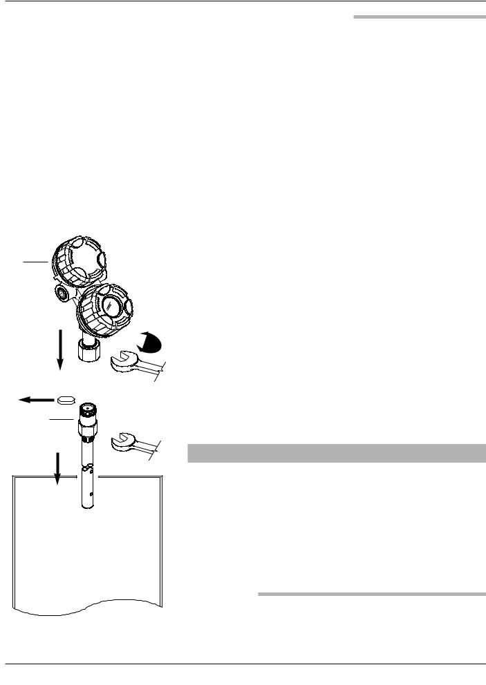
1.2.2 Transmitter
Tighten the hex nut of the probe process connection or flange bolts.
NOTE: Leave the plastic protective cap in place until ready to install the transmitter. Do not use sealing compound or TFE tape on probe connection to transmitter as this connection is sealed by a Viton® O-ring.
Remove the protective plastic cap from the top of the probe and store for future use. Make sure the top probe connector (female socket) is clean and dry. Clean with isopropyl alcohol and cotton swabs if necessary.
Place the transmitter on the probe. Align the universal connection at the base of the transmitter housing with the top of the probe. Hand-tighten the connection.
Rotate the transmitter so that it is in the most convenient position for wiring, configuring, and viewing.
Using a 11⁄2" (38 mm) wrench, tighten the universal connection on the transmitter 1⁄4 to 1⁄2 turn beyond hand-tight. A torque wrench is highly recommended to obtain
45 ft-lbs. This is a critical connection. DO NOT LEAVE HAND-TIGHT.
NOTE: Universal connector can be supplied with lock screws for applications with significant vibration. Contact factory for additional information.
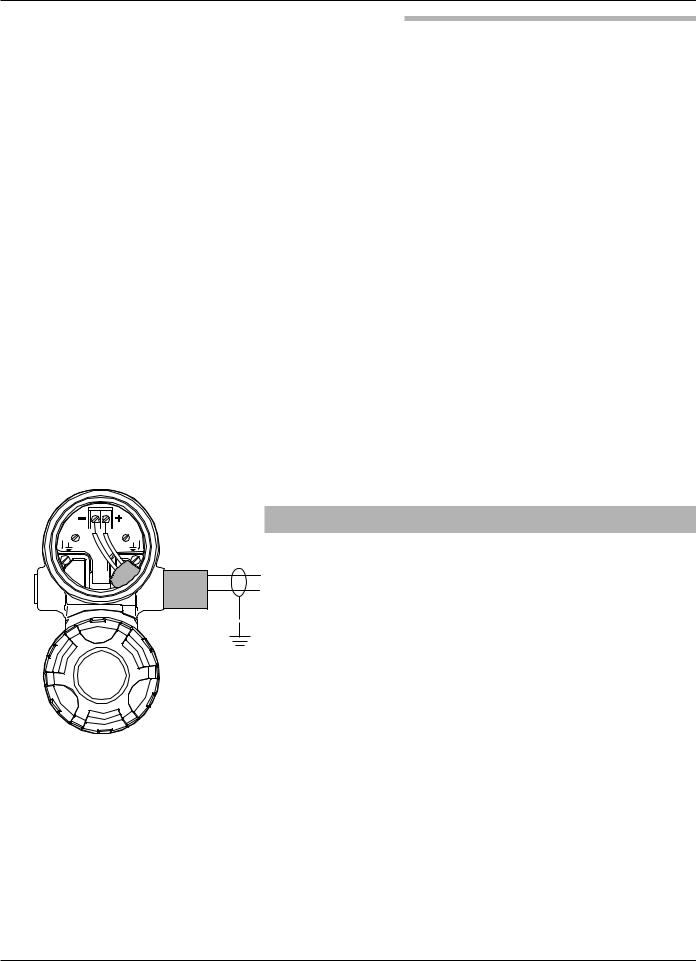
1.3 QuickStart Wiring
Black (-) 
 Red (+)
WARNING! Explosion hazard. Do not connect or disconnect equip-
ment unless power has been switched off or the area is
(+)
known to be non-hazardous.
(-)
NOTE: Ensure that the electrical wiring to the ECLIPSE transmitter is complete and in compliance with all regulations and codes.
1. Remove the cover of the upper wiring compartment of the transmitter.
2. Attach a conduit fitting and mount the conduit plug in the spare opening. Pull the power supply wire through the conduit fitting.
3.Connect shield to an earth ground at power supply.
4.Connect an earth ground to the nearest green ground screw. (Not shown in illustration.)
5.Connect the positive supply wire to the (+) terminal and the negative supply wire to the (-) terminal. For Explosion Proof Installations, see Wiring, Section 2.5.3.
6.Replace the cover and tighten.
6 |
57-600 Eclipse® Guided Wave Radar Transmitter |

 Enter
Enter
Down
Up
|
|
4 |
2 |
Probe Mount |
In or Cm |
9 |
20 mA |
|
(100% Point) |
|
|
|
|
|
1 |
Probe Model |
5 |
|
|
Probe Length |
7Dielectric of Medium
84 mA Level
(0%-point)
 Level Offset 6
NOTE: A small transition zone (0–6") may exist at the top and bottom of the probe. See Specifications,
Section 3.6.
1.4QuickStart Configuration
The ECLIPSE transmitter comes configured with default values from the factory but can be reconfigured in the shop (disregard any fault messages due to unattached probe). The minimum configuration instructions required in the field follow. Use the information from the operating parameters table in Section 1.1.2 before beginning configuration.
1.Power up the transmitter.
The display changes every 5 seconds to show one of four values: Status, Level, %Output, and Loop current.
2.Remove the cover of the lower electronic compartment.
3. |
Use the Up or Down Arrow ( |
) keys to move from one |
|||||
|
step of the configuration program to the next step. |
||||||
4. |
Press the Enter Arrow ( |
|
) key. The last |
|
|
||
|
|
|
|||||
|
|
|
|
|
LvlUnits! |
|
|
|
character in the first line of the display |
|
|||||
|
xxx |
|
|||||
|
changes to an exclamation point (!). |
|
|
||||
5. |
Use the Up or Down Arrow ( |
) keys to increase or |
|||||
|
decrease the value in the display or to scroll through the |
||||||
|
choices. |
|
|
|
|
|
|
6. |
Press the Enter Arrow ( |
|
) key to accept a value and move |
||||
|
|||||||
|
|||||||
|
|
|
|
|
|
||
|
to the next step of the configuration program (the default |
||||||
password is 0).
7.After entering the last value, allow 10 seconds before removing power from the transmitter.
The following configuration entries are the minimum required for configuration (the default password is 0 from the LCD/keypad).
PrbModel(select)
PrbMount(select)
MeasType(select)
Lvl Units
xxx
Probe Ln
xxx.x
Select the Probe Model to be used
Model 705: 7xA-x, 7xB-x, 7xD-x, 7xE-x, 7xF-F, 7xF-P, 7xF-4, 7xF-x, 7xJ-x, 7xK-x, 7xP-x, 7xR-x, 7xS-x, 7xT-x, 7x1-x, 7x2-x, 7x5-x, 7x7-x
Select the type of Probe Mounting to vessel (NPT, BSP, or flange).
Select from Level Only, Level and Volume, Interface Level or Interface Level and Volume.
Select the Units of measurement for the level readout (inches, cm, feet or meters). Not included on Model 705 Fieldbus.
Enter the exact Probe Length as printed on the probe nameplate.
LvlOfst
xxx.x
Dielctrc (select)
Set 4mA xxx.x
Set 20mA
xxx.x
Enter the Level Offset value. Refer to Section 2.6.6 for further information. (The unit is shipped from the factory with offset = 0; i.e., all measurements are referenced to the bottom of the probe).
Enter the Dielectric range for the material to be measured.
Enter the level value (0%-point) for the 4 mA point.
Enter the level value (100%-point) for the 20 mA point.
57-600 Eclipse® Guided Wave Radar Transmitter |
7 |

2.0Complete Installation
This section provides detailed procedures for properly installing and configuring the ECLIPSE Guided Wave Radar Level Transmitter.
2.1Unpacking
Unpack the instrument carefully. Make sure all components have been removed from the packing material. Check all the contents against the packing slip and report any discrepancies to the factory.
Before proceeding with the installation, do the following:
•Inspect all components for damage. Report any damage to the carrier within 24 hours.
•Make sure the nameplate model number on the probe and transmitter agree with the packing slip and purchase order.
•Record the model and serial numbers for future reference when ordering parts.
Model Number
Serial Number
2.2Electrostatic Discharge (ESD) Handling Procedure
Magnetrol® electronic instruments are manufactured to the highest quality standards. These instruments use electronic components that may be damaged by static electricity present in most work environments.
The following steps are recommended to reduce the risk of component failure due to electrostatic discharge.
•Ship and store circuit boards in anti-static bags. If an antistatic bag is not available, wrap the board in aluminum foil. Do not place boards on foam packing materials.
•Use a grounding wrist strap when installing and removing circuit boards. A grounded workstation is recommended.
•Handle circuit boards only by the edges. Do not touch components or connector pins.
•Make sure that all electrical connections are completely made and none are partial or floating. Ground all equipment to a good, earth ground.
8 |
57-600 Eclipse® Guided Wave Radar Transmitter |

2.3Before You Begin
2.3.1Site Preparation
Each ECLIPSE transmitter is built to match the specific physical specifications of the required installation. Make sure the probe connection is correct for the threaded or flanged mounting on the vessel or tank where the transmitter will be placed. See Mounting, Section 2.4.
Make sure that the wiring between the power supply and ECLIPSE transmitter are complete and correct for the type of installation. See Specifications, Section 3.6.
When installing the ECLIPSE transmitter in a general purpose or hazardous area, all local, state, and federal regulations and guidelines must be observed. See Wiring, Section 2.5.
2.3.2Equipment and Tools
No special equipment or tools are required to install the ECLIPSE transmitter. The following items are recommended:
•Open-end wrenches or adjustable wrench to fit the process connection size and type. Coaxial probe 11⁄2" (38 mm), twin rod probe 17⁄8" (47 mm), transmitter 11⁄2" (38 mm). A torque wrench is highly desirable.
•Flat-blade screwdriver
•Digital multimeter or digital volt/ammeter
•24 VDC power supply, 23 mA
2.3.3Operational Considerations
Operating specifications vary based on Probe model number. See Specifications, Section 3.6.
2.4Mounting
The ECLIPSE transmitter can be mounted to a tank using a variety of process connections. Generally, either a threaded or flanged connection is used. For information about the sizes and types of connections available, see Probe Model Numbers, Section 3.7.2.
NOTE: Do not place insulating material around any part of the ECLIPSE transmitter as this may cause excessive heat buildup.
Make sure all mounting connections are properly in place on the tank before installing the probe. Compare the nameplate on the probe and transmitter with the product information; make sure the ECLIPSE probe is correct for the intended installation.
57-600 Eclipse® Guided Wave Radar Transmitter |
9 |

WARNING! The Model 7xD, 7xR or 7xT overfill probes should be used for Safety Shutdown/Overfill applications. All other Guided Wave Radar probes should be installed so the maximum overfill level is a minimum of 6" (150 mm) below the process connection. This may include utilizing a nozzle or spool piece to raise the probe. Consult factory to ensure proper installation.
WARNING! Do not disassemble probe when in service and under pressure.
2.4.1Installing a Coaxial Probe
(Models 7xA, 7xD, 7xG, 7xP, 7xR, 7xS, and 7xT)
Before installing, make sure the:
•Model and serial numbers on the nameplates of the ECLIPSE probe and transmitter are identical.
•Probe has adequate room for installation and has unob-
|
|
|
|
structed entry to the bottom of the vessel. The Model 7xD |
|
|
|
|
(High Temp./High Pressure) probe, Model 7xP (High |
|
|
|
|
Pressure) probe, Model 7xR (Overfill) probe, Model 7xS |
|
|
|
|
(Steam) probe and Model 7xT (Interface) probe require |
|
|
|
|
added clearance. See Physical Specifications, Section 3.6.6. |
|
|
|
• |
Process temperature, pressure, dielectric, and viscosity are |
|
|
|
within the probe specifications for the installation. |
|
|
|
|
|
|
|
|
|
|
See Specifications, Section 3.6. |
|
• |
Model 7xD (High Temp./High Pressure) probes should be |
||
|
|
|
handled with extra care due to the ceramic spacers used |
|
|
|
|
|
throughout their length. |
|
|
|
• |
Model 7xG (caged GWR) probes should be handled |
|
|
|
|
with extra care. Only handle these probes by the flanges. |
|
|
|
2.4.1.1 To install a coaxial probe: |
|
|
|
|
|
Make sure the process connection is at least 3⁄4" NPT or a |
|
|
|
|
flanged mounting. |
|
|
|
Carefully place the probe into the vessel. Align the gasket |
|
|
|
|
|
on flanged installations. |
|
|
|
Align the probe process connection with the threaded or |
|
|
|
|
|
flanged mounting on the vessel. |
|
|
|
For threaded connections, tighten the hex nut of the probe |
|
|
|
|
|
process connection. For flanged connections, tighten flange |
|
|
|
|
bolts. |
|
|
|
NOTE: If the transmitter is to be installed at a later time, do not remove |
|
|
|
|
|
the protective cap from the probe. Do not use sealing com- |
|
|
|
|
pound or TFE tape on probe connection to transmitter as this |
|
|
|
|
connection is sealed by a Viton® O-ring. |
|
|
|
NOTE: For applications using the Model 7xS steam probe, it is manda- |
|
|
|
|
|
tory to keep the transmitter and probe matched as a set. |
10 |
57-600 Eclipse® Guided Wave Radar Transmitter |
2.4.2Installing a Twin Rod Probe (Models 7xB, 7x5, and 7x7)
Before installing, make sure the:
•Model and serial numbers on the nameplates of the ECLIPSE probe and transmitter are identical.
•Probe has adequate headroom for installation and has unobstructed entry to the bottom of the vessel.
•Process temperature, pressure, dielectric, viscosity, and media buildup are within the probe specifications for the installation. See Specifications, Section 3.6.
Nozzles:
The 7xB/7x5/7x7 Twin Rod probes may be susceptible to objects that are in close proximity. The following rules should be followed for proper application:
1.Nozzles should be 3" (80 mm) diameter or larger.
2.7xB/7x5/7x7 Twin Rod probes should be installed such that the active rod is >1" (25 mm) from metallic objects such as pipes, ladders, etc., (a bare tank wall parallel to the probe is acceptable).
|
|
|
|
||
|
|
|
Active |
Inactive |
|
probe rod |
probe rod |
|
|
|
|
|
|
|
2.4.2.1 To install a rigid twin rod probe:
Make sure the process connection is at least 2" NPT or a flanged mounting.
Make sure that there is at least 1" (25 mm) spacing between the active probe rod and any part of the tank (walls, stillwell, pipes, support beams, mixer blades, etc.). Minimum stillwell diameter for Twin Rod probe is 3".
Carefully place the probe into the vessel. Align the gasket on flanged installations.
Align the probe process connection with the threaded or flanged mounting on the vessel.
For threaded connections, tighten the hex nut of the probe process connection. For flanged connections, tighten flange bolts.
Probe can be stabilized by attaching the inactive probe rod to vessel.
NOTE: If the transmitter is to be installed at a later time, do not remove the protective cap from the probe. Do not use sealing compound or TFE tape on probe connection to transmitter as this connection is sealed by a Viton® O-ring.
57-600 Eclipse® Guided Wave Radar Transmitter |
11 |
|
|
|
|
|
|
2.4.2.2 To install a Model 7x7 standard flexible twin rod probe:
Make sure the process connection is at least 2" NPT or a flanged mounting.
Make sure that there is at least 1" (25 mm) spacing between the active probe rod and any part of the tank (walls, stillwell, pipes, support beams, mixer blades, etc.). Minimum stillwell diameter for Twin Rod probe is 3".
Carefully place the probe into the vessel. Align the gasket on flanged installations.
Align the probe process connection with the threaded or flanged mounting on the vessel.
For threaded connections, tighten the hex nut of the probe process connection. For flanged connections, tighten flange bolts.
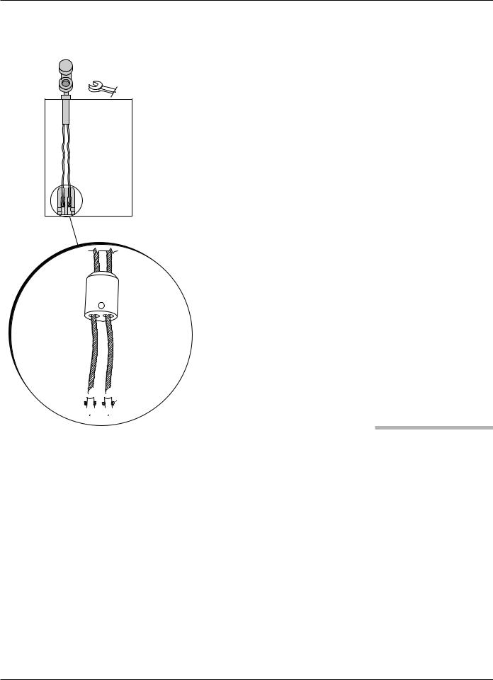
Probe can be shortened in the field:
a. Raise the weight (1) to expose the two securing devices (2).
1
 0.50" (13 mm) Ø


 3 2
3 2


 4
4
b.Loosen the two #10-32 set screws (3) on both securing devices using a 3⁄32" (2.5 mm) hex wrench and slide the securing devices off of the probe.
c.Slide the TFE weight off of the probe.
d.Cut and remove the required cable (4) length.
e.Remove 31⁄2" of the rib between the two cables.
f.Strip 5⁄8" (16 mm) of coating from the two cables.
g.Slide the TFE weight back on to the probe.
h.Reattach securing device and tighten screws.
i.Enter new probe length (inches or cm) in software.
2.4.3Installing a Single Rod Probe (Models 7x1, 7x2, 7xF, 7xJ)
Before installing, make sure the:
•Model and serial numbers on the nameplates of the ECLIPSE probe and transmitter are identical.
•Probe has adequate headroom for installation and has unobstructed entry to the bottom of the vessel.
•Process temperature, pressure, dielectric, viscosity, and media buildup are within the probe specifications for the installation. See Specifications, Section 3.6.
•Nozzle does not restrict performance by ensuring the following:
1.No nozzle is <2" (50mm) diameter.
12 |
57-600 Eclipse® Guided Wave Radar Transmitter |
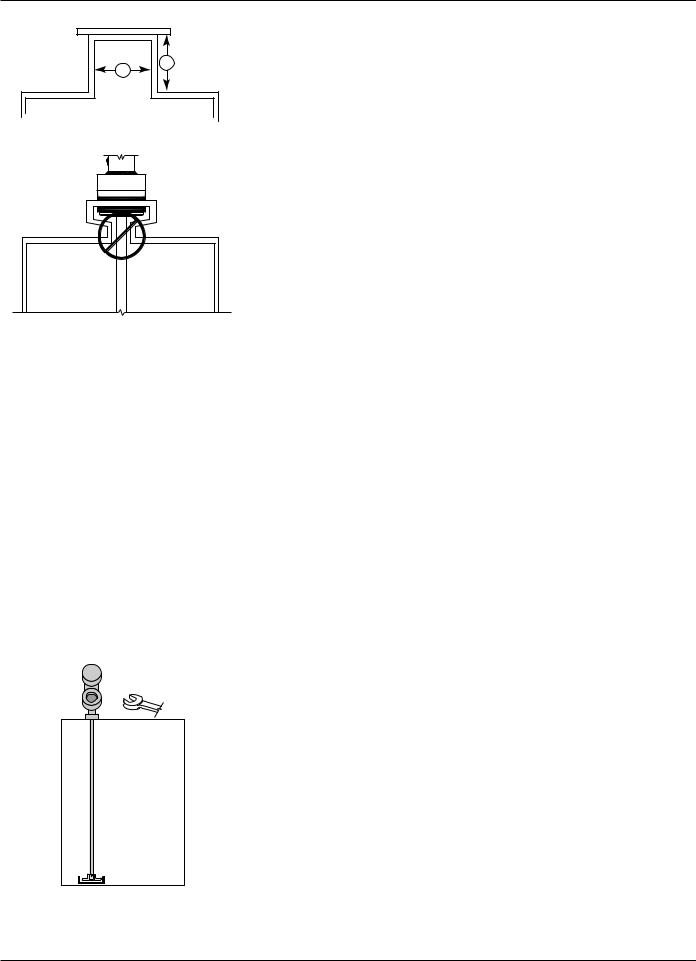
B |
A |
2.Ratio of Diameter: Length (A:B) is 1:1 or greater; any ratio <1:1 (e.g., a 2"× 6" nozzle = 1:3) may require a Blocking Distance and/or DIELECTRIC adjustment (see Section 2.6.5.2 Measurement Type: Level and Volume).
3.No pipe reducers (restrictions) are used.
•Probe is kept away from conductive objects to ensure proper performance. See Probe Clearance Table below. A lower gain (increase in DIELECTRIC setting) may be necessary to ignore certain objects (see Section 2.6.5.4 Measurement Type: Interface and Volume).
PROBE CLEARANCE TABLE
Distance |
|
to Probe |
Acceptable Objects |
|
|
<6" |
Continuous, smooth, parallel conductive |
|
surface, for example a metal tank wall; |
|
important that probe does not touch wall |
|
|
>6" |
<1" (25mm) diameter pipe and beams, |
|
ladder rungs |
|
|
>12" |
<3" (75mm) diameter pipe and beams, |
|
concrete walls |
>18" |
All remaining objects |
|
|
|
|
|
|
2.4.3.1 To install a Model 7xF rigid single rod probe:
Make sure the process connection is at least 2" NPT or a flanged mounting.
Carefully place the probe into the vessel. Align the gasket on flanged installations.
Align the probe process connection with the threaded or flanged mounting on the vessel.
For threaded connections, tighten the hex nut of the probe process connection. For flanged connections, tighten flange bolts.
Probe can be stabilized by placing into a non-metallic cup or bracket at the bottom of the probe. A TFE bottom spacer (P/N 89-9114-001) is optional for mounting into a metallic cup or bracket.
NOTE: If the transmitter is to be installed at a later time, do not remove the protective cap from the probe. Do not use sealing compound or TFE tape on probe connection to transmitter as this connection is sealed by a Viton® O-ring.
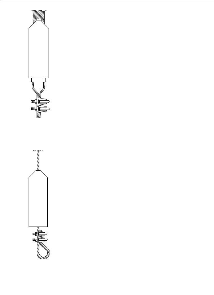
2.4.3.2 To install a Model 7x1 flexible single rod probe:
Make sure the process connection is at least 2" NPT or a flanged mounting.
Carefully place the probe into the vessel. Align the gasket on flanged installations.
57-600 Eclipse® Guided Wave Radar Transmitter |
13 |

|
|
|
Align the probe process connection with the threaded or |
|
|
|
|
|
flanged mounting on the vessel. |
|
|
For threaded connections, tighten the hex nut of the probe |
||
|
|
|
|
process connection. For flanged connections, tighten flange |
|
|
|
|
bolts. |
|
|
|
Probe can be shortened in field: |
|
|
|
|
|
a. Raise TFE weight (1) exposing securing device (2). |
|
|
|
|
b. Loosen both #10–32 set screws (3) using 3⁄32" (2.5 mm) |
|
|
|
|
hex wrench and remove securing device. |
|
|
|
|
c. Cut and remove needed cable (4) length. |
|
|
|
d. Reattach securing device and tighten screws. |
|
|
|
|
|
|
|
|
|
|
e. Enter new probe length (inches or cm) in software. |
|
|
|
Probe can be attached to the tank bottom using the |
|
|
|
|
|
0.50" (13 mm) hole provided in the TFE weight. |
|
1 |
|
|
Cable tension should not exceed 20 lbs. |
|
|
|
|
|

 0.50" (13 mm) Ø
2


 3
3
4


2.4.4Installation Guidelines
Models 7x2/7x5 Bulk Solids Probes
The Model 7x2 and 7x5 Bulk Solids probes are designed for a 3000 lb. (1360 kg) pull-down force for use in applications such as sand, plastic pellets and grains. It is offered with a
maximum 75-foot (22-meter) probe length. Model 7x2 Single Rod — dielectric ≥4 Model 7x5 Twin Rod — dielectric ≥1.9
NOTE: Avoid cement, heavy gravel, etc.
2.4.4.1 Applications
1.Plastic pellets, sugar: Dielectric constant 1.9-2.0
2.Grain, seeds, sand: Dielectric constant 2.0-3.0
3.Salts: Dielectric constant 4.0-7.0
4.Metallic powder, coal dust: Dielectric constant >7
2.4.4.2 Mounting recommendations
1.Use a weight instead of securing the probe to the vessel.
2.Mount probe at least 12 inches from the wall. Ideal location is 1⁄4 to 1⁄6 the diameter to average the angle of repose.
3.A metal flange must be used when mounting on plastic vessels.
2.4.4.3 To install a Model 7x5 bulk solids flexible twin rod probe:
Make sure the process connection is at least 2" NPT or a flanged mounting.
14 |
57-600 Eclipse® Guided Wave Radar Transmitter |
Model 7x5 Dual Rod
Bulk Solids Probe
Model 7x2 Single Rod
Bulk Solids Probe
Make sure that there is at least 1" (25 mm) spacing between the active probe rod and any part of the tank (walls, stillwell, pipes, support beams, mixer blades, etc.). Minimum stillwell diameter for Twin Rod probe is 3".
Carefully place the probe into the vessel. Align the gasket on flanged installations.
Align the probe process connection with the threaded or flanged mounting on the vessel.
For threaded connections, tighten the hex nut of the probe process connection. For flanged connections, tighten flange bolts.
Refer to Bulk Solid Guidelines, Section 2.4.4.
Probe can be shortened in the field:
a. Loosen and remove the two cable clamps.
b. Slide the weight off of the probe.
c. Cut the cable to the required length.
d. Remove 12 inches of the rib between the two cables.
e. Strip 6 inches of coating from the two cables.
f. Slide the weight back on to the probe.
g. Reinstall the two cable clamps and tighten.
h. Enter the new probe length (inches or cm) in software.
2.4.4.4 To install a Model 7x2 bulk solids flexible single rod probe:
Make sure the process connection is at least 2" NPT or a flanged mounting.
Carefully place the probe into the vessel. Align the gasket on flanged installations.
Align the probe process connection with the threaded or flanged mounting on the vessel.
For threaded connections, tighten the hex nut of the probe process connection. For flanged connections, tighten flange bolts.
Probe can be shortened in field:
a.Loosen and remove the two cable clamps.
b.Slide the weight off of the probe.
c.Cut the cable to the required length plus 6.38".
d.Slide the weight back on to the probe.
e.Reinstall the two cable clamps and tighten.
f.Enter the new probe length (inches or cm) in software.
57-600 Eclipse® Guided Wave Radar Transmitter |
15 |


|
|
|
|
|
|


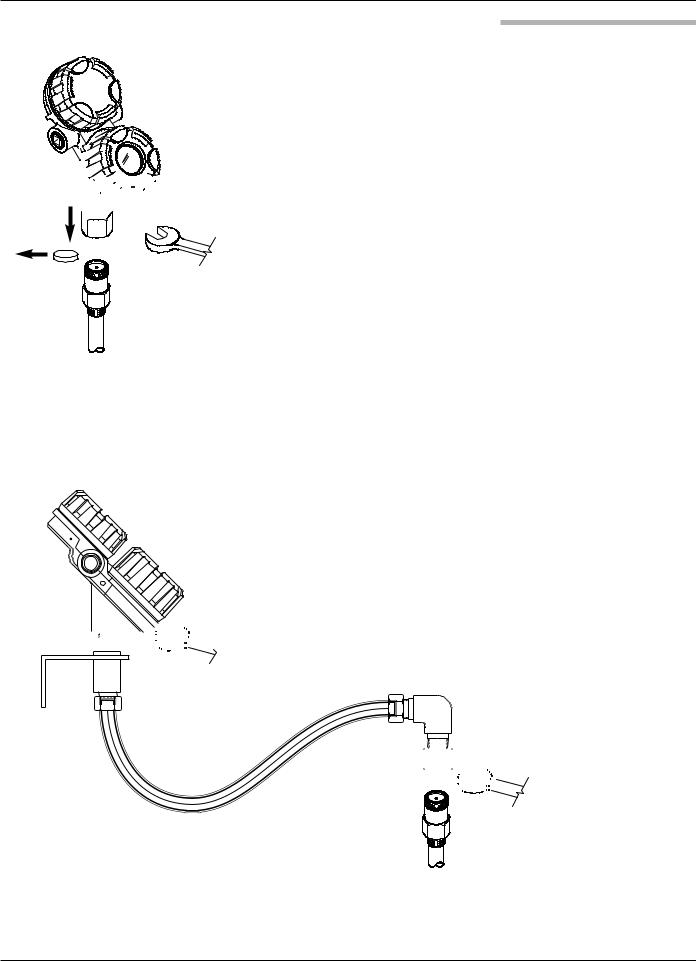
2.4.5Installing the Transmitter
The transmitter can be ordered for installation as an Integral or Remote configuration.
2.4.5.1 Integral Mount
Remove the protective plastic cap from the top of the probe. Store the cap in a safe place in case the transmitter has to be removed later.
Place the transmitter on the probe. Be careful not to bend probe. Do not allow the gold, high frequency (male) connector to get dirty.
Align the universal connection at the base of the transmitter housing with the top of the probe. Hand-tighten the connection.
Rotate the transmitter to face the most convenient direction for wiring, configuration, and viewing.
When the transmitter is facing the desired direction, use a 11⁄2" (38 mm) wrench to tighten the universal connection on the transmitter to 45 ft-lbs. A torque wrench is highly recommended. This is a critical connection. DO NOT LEAVE HAND-TIGHT.
2.4.5.2 Remote Mount
Mount the transmitter/remote bracket as an assembly within 33" or 144" (84 or 366 cm) of the probe. DO NOT REMOVE TRANSMITTER FROM BRACKET.
Remove the protective plastic cap from the top of the probe. Store the cap in a safe place in case the transmitter has to be removed later.
Align the universal connection at the end of the remote assembly with the top of the probe. Using a 11⁄2" (38 mm) wrench, tighten the universal connection on the transmitter to 45 ft-lbs. A torque wrench is highly recommended. This is a critical connection. DO NOT LEAVE HAND-TIGHT.


NOTE: Remote mounting is recommended for all cast 316 SS enclosures due to their extra weight.
16 |
57-600 Eclipse® Guided Wave Radar Transmitter |

2.5Wiring
Caution: All HART versions of the ECLIPSE Model 705 transmitter operate at voltages of 11–36 VDC. Higher voltage will damage the transmitter.
Wiring between the power supply and the ECLIPSE transmitter should be made using 18–22 AWG shielded twisted pair instrument cable. Within the transmitter enclosure, connections are made to the terminal strip and the ground connections. The directions for wiring the ECLIPSE transmitter depend on the application:
•General Purpose or Non-incendive (Cl I, Div. 2)
•Intrinsically Safe
•Explosion Proof
WARNING! Explosion hazard. Do not disconnect equipment unless power has been switched off or the area is known to be non-hazardous.
2.5.1General Purpose or Non-Incendive (Cl I, Div. 2)
A general purpose installation does not have flammable media present. Areas rated non-incendive (Cl I, Div. 2) have flammable media present only under abnormal conditions. No special electrical connections are required.
Caution: If flammable media is contained in the vessel, the transmitter must be installed per Cl I, Div. 1 standards of area classification.
Black (-) |
Red (+) |
|
|
|
|
To install General Purpose or Non-Incendive wiring: |
|
|
(+) |
1. Remove the cover to the wiring compartment of the trans- |
|
|
(-) |
|
mitter. Install the conduit plug in the unused opening. |
|
|
|
|
|
|
|
Use PTFE tape/sealant to ensure a liquid-tight connection. |
|
|
2. |
Install a conduit fitting and pull the supply wires. |
|
|
3. |
Connect shield to an earth ground at power supply. |
|
|
4. |
Connect an earth ground wire to the nearest green ground |
|
|
|
screw (not shown in illustration). |
|
|
5. |
Connect the positive supply wire to the (+) terminal and |
|
Wiring Diagram |
|
the negative supply wire to the (-) terminal. |
|
6. |
Replace the cover to the wiring compartment of the |
|
|
|
||
transmitter.
57-600 Eclipse® Guided Wave Radar Transmitter |
17 |
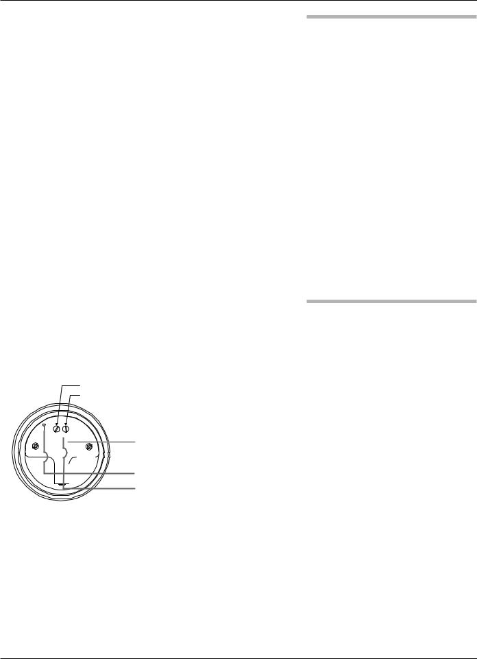
(-) negative
(+) positive
|
|
|
|
+ |
|
||
|
|
|
|
|
|||
|
|
|
|
Power Supply |
|||
|
|
|
|
||||
|
|
|
|
|
|
|
|
|
|
|
|
|
|
|
|
|
|
|
|
|
|
|
24 VDC |
|
|
|
|
|
|
– |
|
|
|
|
|
|
|
|
|
|
|
|
|
|
|
– |
|
|
|
|
|
|
|
|
|
|
|
|
|
|
|
|
|
|
Current Meter |
||||||
|
|
|
|
+ |
Test |
||
|
|
|
|
|
|
|
Current Meter |
|
|
|
|
|
|
|
|
G.P./I.S./Explosion Proof Model
2.5.2Intrinsically Safe
An intrinsically safe (IS) installation potentially has flammable media present. An approved IS barrier must be installed in the non-hazardous (safe) area. See Agency Drawing – Intrinsically Safe Installation, Section 3.4.2.
To install Intrinsically Safe wiring:
1.Make sure the IS barrier is properly installed in the safe area (refer to local plant or facility procedures). Complete the wiring from the barrier to the ECLIPSE transmitter.
2.Remove the cover to the wiring compartment of the transmitter. Install the conduit plug in the unused opening. Use PTFE tape/sealant to ensure a liquid-tight connection.
3.Install a conduit fitting and pull the supply wires.
4.Connect shield to an earth ground at power supply.
5.Connect an earth ground wire to the nearest green ground screw (not shown in illustration).
6.Connect the positive supply wire to the (+) terminal and the negative supply wire to the (-) terminal.
7.Replace the cover to the wiring compartment of the transmitter.
2.5.3Explosion Proof
Explosion Proof (XP) is a method of designing equipment for installation in hazardous areas. A hazardous location is an area in which flammable gases or vapors are, or may be, present in the air in quantities sufficient to produce explosive or ignitable mixtures. The wiring for the transmitter must be contained in Explosion Proof conduit extending into the safe area. Due to the specialized design of the ECLIPSE transmitter, no Explosion Proof conduit fitting (EY seal) is required within 18" of the transmitter. An Explosion Proof conduit fitting (EY seal) is required between the hazardous and safe areas. See Agency Specifications, Section 3.4.1.
To install Explosion Proof wiring:
1.Install Explosion Proof conduit from the safe area to the conduit connection of the ECLIPSE transmitter (refer to local plant or facility procedures).
2.Remove the cover to the wiring compartment of the transmitter.
3.Connect shield to an earth ground at the power supply.
4.Connect an Earth ground wire to the nearest green ground screw per local electrical code (not shown in illustration).
5.Connect the positive supply wire to the (+) terminal and the negative supply wire to the (-) terminal.
6.Replace the cover to the wiring compartment of the transmitter before applying power.
18 |
57-600 Eclipse® Guided Wave Radar Transmitter |

(-) negative
(+) positive
|
|
|
|
+ |
|
||
|
|
|
|
|
|||
|
|
|
|
|
|||
|
|
|
|
|
|
|
Power Supply |
|
|
|
|
|
|
|
24 VDC |
|
|
|
|
|
|
– |
|
|
|
|
|
|
|
– |
|
|
|
|
|
|
|
|
|
|
|
|
|
|
|
|
|
|
Current Meter |
||||||
|
|
|
|
+ |
Test |
||
|
|
|
|
|
|
|
Current Meter |
|
|
|
|
|
|
|
|
G.P./I.S./Explosion Proof Model
2.6Configuring the Transmitter
The ECLIPSE transmitter comes configured from the factory but can be reconfigured easily in the shop (disregard error message due to unattached probe). Bench configuration provides a convenient and efficient way to set up the transmitter before going to the tank site to complete the installation.
Before configuring the transmitter, collect the operating parameters information (refer to Section 1.1.2). Power up the transmitter on the bench and follow through the step- by-step procedures for the menu-driven transmitter display.
Information on configuring the transmitter using a HART communicator is given in Configuration Using HART, Section 2.7.
Information on configuring the transmitter using FOUNDATION fieldbus is given in Section 2.8.
Refer to instruction manual 57-640 for detailed FOUNDATION fieldbus information.
2.6.1Operating Parameters
Some key information is needed to calibrate the ECLIPSE transmitter. Complete the configuration information table in Section 1.1.2.
2.6.2Setting Up for Bench Configuration
The ECLIPSE transmitter can be configured at a test bench by connecting a 24 VDC power supply directly to the transmitter terminals as shown in the accompanying diagram. An optional digital multimeter is shown if current measurements are desired.
NOTE: Current measurements taken at these test points is an approximate value. Accurate current readings should be taken with the digital multimeter in series with the loop.
1.When using a HART communicator for configuration, a minimum 250 Ω line load resistance is required. See the HART communicator manual for more information.
2.The transmitter can be configured without the probe. (Disregard the error message due to the unattached probe.)
3.After entering the last value, allow 10 seconds before removing power from the transmitter. This allows the transmitter to store values.
57-600 Eclipse® Guided Wave Radar Transmitter |
19 |

 Enter
Enter
Down
Up
2.6.3Transmitter Display and Keypad
The ECLIPSE transmitter has an optional liquid crystal display (LCD) capable of showing two lines of 8 characters each. Transmitter measurements and configuration menu screens are shown on the LCD.
The transmitter default display is the measurement screen. It cycles every 5 seconds to display STATUS, LEVEL, %OUTPUT, and LOOP information (LEVEL, %OUTPUT, and STATUS for Fieldbus version). The transmitter defaults to this display after 5 minutes if no keystrokes are sensed.
|
|
The keypad has three arrows used to scroll through the dis- |
|||||
|
|
plays and to calibrate the transmitter. The Up and Down |
|||||
|
|
Arrow ( |
) keys and the Enter ( |
|
|
) key. |
|
|
|
|
|||||
|
|
|
|
|
|
|
|
|
|
|
|
|
|||
|
Arrows |
Function in |
Function in |
||||
|
Display Mode |
Configuration Mode |
|||||
|
Up and Down Moves forward and backward |
Increases or decreases the |
|||||
|
in the configuration program |
value displayed or moves to |
|||||
|
|
another choice. |
|||||
|
|
from one display to another. |
|||||
|
|
|
|
NOTE: Hold arrow key for |
|||
|
|
|
|
rapid scrolling. |
|||
|
Enter |
Enters the configuration mode |
Accepts a value and moves |
||||
|
|
(noted by an exclamation point |
to the next step of the |
||||
|
as the last character in the top |
configuration program. |
|||||
|
|
||||||
display line).
2.6.4Password Protection (Default = 0)
The ECLIPSE transmitter is password protected to restrict access to certain portions of the menu structure that affect the operation of the system. When the proper password is entered, an exclamation point (!) appears as the last character of the first line of the display. The password can be changed to any numerical value up to 255. The password is required whenever configuration values are changed.
The default user password installed in the transmitter at the factory is 0. The last step in the configuration menu provides the option to enter a new password. With a password of 0, the transmitter is no longer password protected and any value in the menu can be adjusted without entering a confirming password, except diagnostic values.
NOTE: If the password is not known, the menu item New Password displays an encrypted value representing the present password. Call the factory with this encrypted value to determine the present password.
20 |
57-600 Eclipse® Guided Wave Radar Transmitter |
2.6.5Model 705 Menu: Step-By-Step Procedure
The following tables provide a complete explanation of the software menus displayed by the ECLIPSE transmitter. Use these tables as a step-by-step guide to configure the transmitter based on a desired measurement type of:
•Level Only, Section 2.6.5.1
•Level and Volume, Section 2.6.5.2
•Interface Level, Section 2.6.5.3
•Interface Level and Volume, Section 2.6.5.4
The tables are separated to display the parameters based on the measurement type. The second column presents the menus shown on the transmitter display. The displays are in the order they would appear if the arrow keys were used to scroll through the menu. The numbers in the first column are not shown on the display. They are only provided as a reference.
The third column provides the actions to take when configuring the transmitter. Additional information or an explanation of an action is given in the fourth column. (Shaded sections are factory menu items).
2.6.5.1 Measurement Type: Level Only (Loop Control = Level)
|
|
Display |
Action |
Comment |
|
|
*Status* |
Transmitter Display |
LoopCtrl = Level. |
|
1 |
*Level * |
|
Transmitter default display showing Status, Level, % Output, and |
|
*% Out * |
|
||
|
|
* Loop * |
|
Loop values cycles every 5 seconds |
|
|
|
|
|
|
2 |
Level |
Transmitter Display |
Transmitter displays Level Value in selected units |
|
xxx.x |
|
|
|
|
|
|
|
|
|
|
|
|
|
|
3 |
% Output |
Transmitter Display |
Transmitter displays % Output measurement derived from 20 mA |
|
xx.x% |
|
span |
|
|
|
|
||
|
|
|
|
|
|
4 |
Loop |
Transmitter Display |
Transmitter displays Loop value (mA) |
|
xx.xx mA |
|
|
|
|
|
|
|
|
|
|
|
|
|
|
|
|
Select the type of probe |
Select from 7xA-x, 7xB-x, 7xD-x, 7xE-x, 7xF-x, 7xF-E, 7xF-F, |
|
5 |
PrbModel |
used |
7xF-4, 7xG-x, 7xF-P, 7xG, 7xJ-x, 7xK-x, 7xL, 7xM, 7xN, 7xP-x, |
|
|
7xR-x, 7xS-x, 7xT-x, 7x1-x, 7x2-x, 7x5-x, 7x7-x as shown on |
||
|
(select) |
(Example: 7xR-x) |
||
|
|
|||
|
|
|
the probe nameplate |
|
|
|
|
|
|
|
|
|
|
|
|
6 |
PrbMount |
Select the type of probe |
Select from NPT, BSP, or Flange |
|
(select) |
mounting |
|
|
|
|
|
||
|
|
|
|
|
|
7 |
MeasType |
Select type of measurement |
Select Lvl Only |
|
(select) |
|
|
|
|
|
|
|
|
|
|
|
|
|
|
8 |
LvlUnits |
Select level units |
Select from cm, inches, feet or meters |
|
(select) |
|
|
|
|
|
|
|
|
|
|
|
|
|
|
9 |
Probe Ln |
Enter the exact length of |
Probe length is printed on the nameplate and order information |
|
xxx.x |
probe |
and is the last three digits of the probe model number |
|
|
|
|||
|
|
|
|
|
|
10 |
Lvl Ofst |
Enter the desired reading |
Level Offset is the distance from the probe tip to the desired 0 |
|
xxx.x |
when probe is dry |
level point (-90 to 300"). Refer to Section 2.6.6 |
|
|
|
|||
|
|
|
|
|
|
|
Dielctrc |
Select range bounding the |
Select from 1.4–1.7; 1.7–3; 3–10; 10–100 |
|
11 |
dielectric constant of the |
|
|
|
|
(select) |
media |
|
|
|
|
|
|
|
|
|
|
|
|
|
|
|
|
57-600 Eclipse® Guided Wave Radar Transmitter |
21 |
Loading...